1. Introduction
Layer thickness is a crucial factor in Additive Manufacturing (AM), also known as 3D printing, impacting various aspects of the process and the resulting component’s properties. It significantly influences resolution and surface finish, with lesser layer thickness yielding finer details and smoother surfaces. Smaller layer thickness increases build time and cost as it requires more layers to achieve a given part height than higher layer thickness [
1]. However, higher layer thickness has to compromise accuracy and surface quality [
2,
3]. Layer thickness also influences mechanical properties with smaller layer thickness, enhancing inter-layer bonding for greater strength [
4,
5]. Directed Energy Deposition (DED) is one class of AM which utilizes metal powder or wire as feedstock and uses a laser, arc or electron beam as a thermal energy source to melt the material for deposition [
6]. Powder feedstock has a low yield due to high wastage, and therefore, wire feedstock becomes more prominent [
7]. Wire Arc Additive Manufacturing (WAAM) is an emerging metal AM technology facilitating the cost-effective production of medium to large metal parts, driven by its outstanding material utilization (>90%) and improved energy efficiency [
8,
9,
10]. It employs an electric arc to melt wire and construct components layer by layer. Further post-processing, such as milling, turning, and grinding, is required because the WAAM process produces near-net shapes with low dimensional accuracy and surface quality [
11,
12]. These machining operations determine the component’s surface integrity, residual stresses, microstructural deformations, and longevity [
13,
14,
15]. However, other techniques, such as pre-heating [
16], hammering [
17], process selection [
18], fixture design [
19] etc., also have significant effects on the various aspects of the WAAM components.
During machining, material microstructure evolves through the combined influence of thermal and mechanical interactions, with plastic deformation significantly advancing this evolution [
20]. The generation of residual stresses in machining can be attributed to non-uniform plastic deformation resulting from the mechanical and thermal processes associated with chip formation (cutting) and the interaction between the tool’s nose and the freshly machined workpiece surface (compression). These forces, acting parallel and perpendicular to the surface, develop compressive residual stresses [
21,
22]. Numerous studies have investigated the impact of layer thickness on the build time and mechanical characteristics of metal additive manufacturing [
4,
5,
23,
24]. Additionally, various researchers have investigated the influence of machining on the microstructure evolution and residual stress of machined surfaces [
25,
26,
27,
28,
29]. Few researchers have studied the effect of substrate and layer thickness on residual stress, heat input and deformation in WAAM [
18,
30,
31]. Nevertheless, there is a noticeable gap in exploring the combined effects of layer thickness by interlayer machining on the mechanical properties and reduction of residual stress in WAAM surfaces. This study aims to fill this void by providing insights into how adjusting layer thickness by incorporating interlayer machining can enhance mechanical properties and reduce residual stress in WAAM components.
2. Materials and Methods
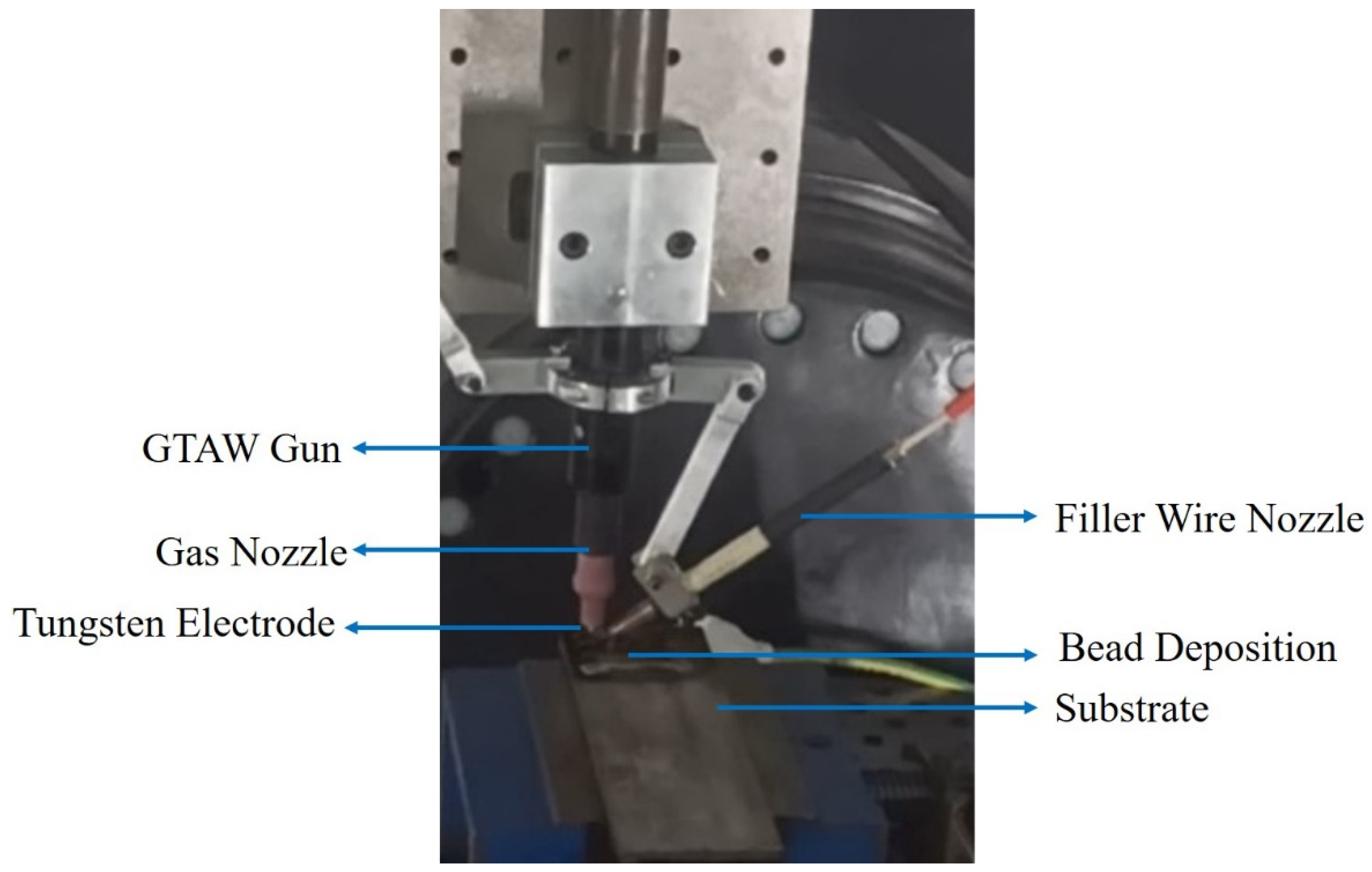
Four different sample blocks (S1-S4) were deposited using the material mild steel (grade ER70S-6) in the wire form of 1.2 mm diameter by Fronius Magic WAVE 2700 Gas Tungsten Arc Welding (GTAW) (Fronius, Wels, Austria, Austria-based company) with customized wire feeding assembly, as shown in
Figure 1. The chemical composition of ER70S-6 is shown in the
Table 1 [
32]. The welding parameters were optimized with trial experiments and taken as current-150A, welding speed-800 mm/min and voltage-14V.
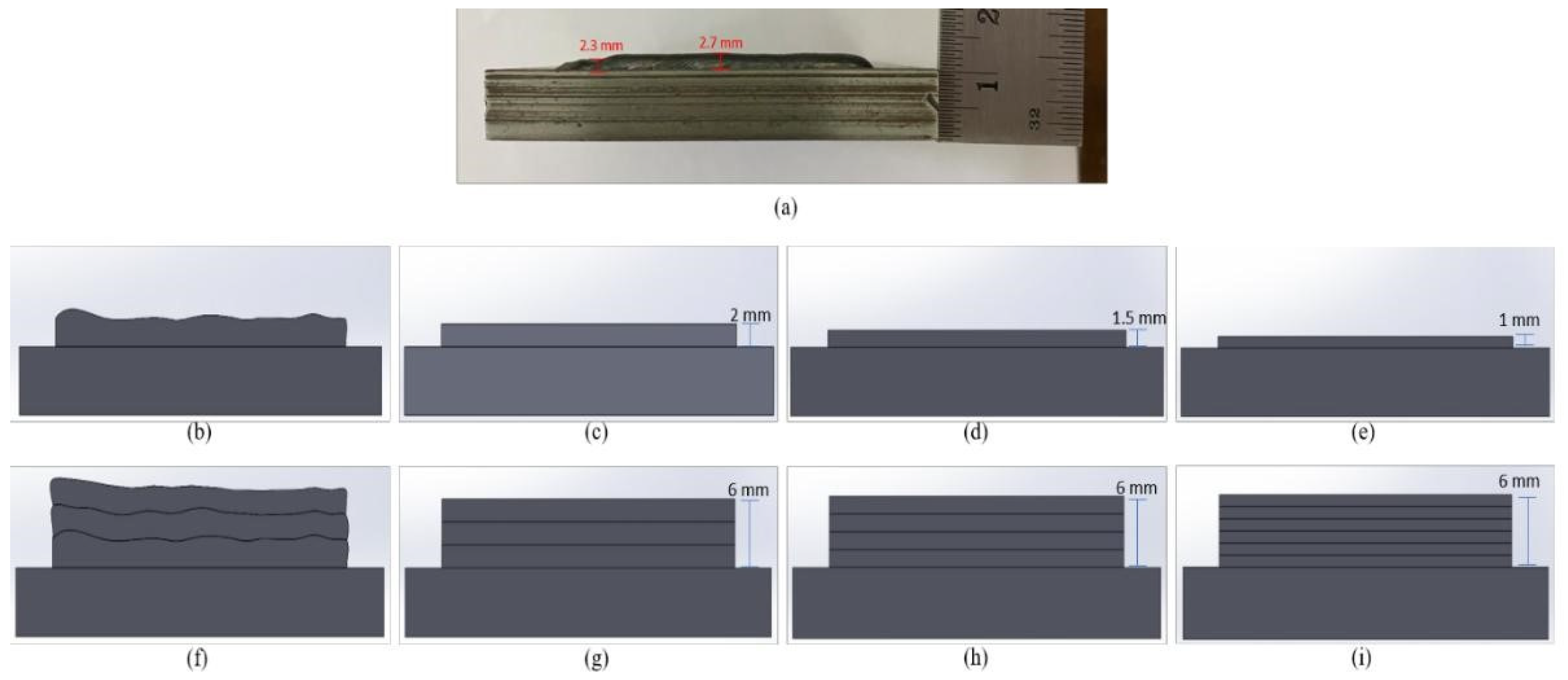
Figure 2 presents samples in various scenarios. Bead height in a single layer of deposition ranged from 2.3 - 2.7 mm (
Figure 2a). Four samples were prepared to assess multi-pass machining’s impact on residual stress, microstructure, and mechanics. The initial sample (S1) was manufactured without any machining (
Figure 2b), consisting of three consecutive deposition layers (
Figure 2f). Subsequently, the second sample (S2) was manufactured with single-pass machining applied after each deposition layer. In this process, layer thickness was maintained at 2mm, and this procedure was iterated over three layers, resulting in an aggregate layer height of 6mm (as illustrated in
Figure 2 c&g). For the third sample, denoted as S3, two machining passes were executed, and layer thickness of 1.5mm was maintained, and a total of four such layers were deposited (
Figure 2d&h). In the case of the fourth sample, S4, three machining passes were carried out to attain a layer thickness of 1mm, and this sequence was repeated six times to achieve a final height of 6mm (
Figure 2 e&i). The machining process encompassed a depth of cut of 0.5mm, a spindle speed set at 2,000 rpm, and a feed rate of 800 mm/min constant for all samples
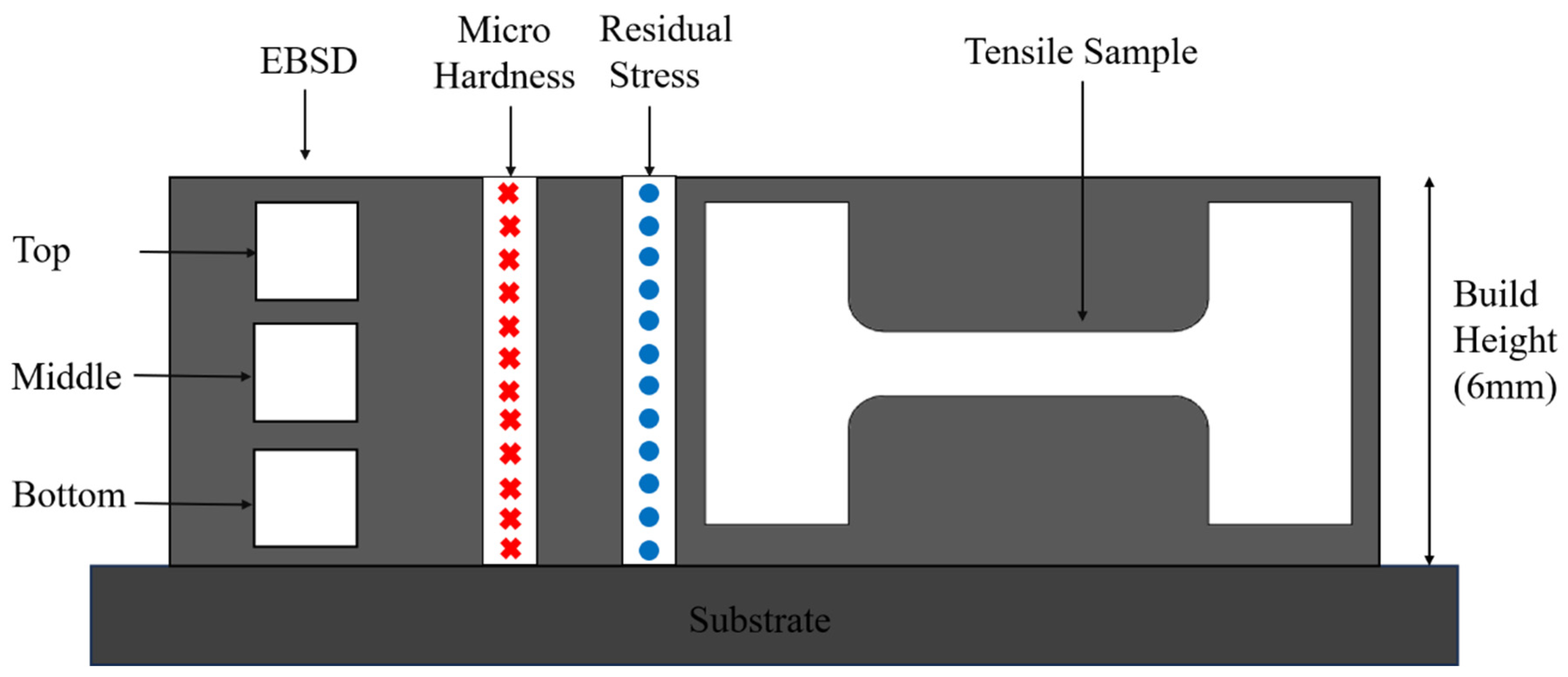
Samples extracted by wire-electric discharge machining (W-EDM) from the various places of deposited block were used for characterization and testing, as illustrated in
Figure 3. Microstructure examination utilized Electron Back Scattered Diffraction (EBSD) (Zeiss Gemini SEM 300 [Carl Zeiss AG, Oberkochen, Germany, German based company. following grinding and colloidal polishing. Vickers microhardness using Innovatest Model 41 2D (INNOVATEST, Maastricht, The Netherlands, Netherland-based company) tests applied a 500g load for 10 seconds on polished samples. Miniature tensile test samples were machined from build surfaces, with a 5 mm gauge length, 2 mm width [
33], tested on the Tinius Olsen, Model H25KS (Tinius Olsen, Horsham, PA, USA, USA-based company). The residual stress was measured by XRD using a PANalytical model, System-EMPYREAN (Malvern Panalytical Almelo, Netherlands, Netherland-based company) with the following parameters: Cu target (K α average 1.5405 N-m), a tilt angle range of 0-40° in 8° intervals, and in-plane rotation angles of [0°, 45°, 90°] in the first quadrant, [180°, 225°, and 270°] in third quadrant, with a 2θ value of 82.4° and the (2,1,1) plane. All reported values (microhardness, ultimate tensile strength, and residual stress) represent averages from three measurements.
3. Results and Discussion
This section explores the influence of varying layer thickness achieved through interlayer machining on microstructure evolution and mechanical properties. It examines how layer thickness affects grain refinement and distribution, highlighting its role in altering microstructural characteristics. Additionally, the section evaluates changes in mechanical properties such as microhardness, ultimate tensile strength, yield strength, and elongation. Furthermore, it discusses the impact of layer thickness on residual stress distribution in the X and Y directions, emphasizing the benefits of machining in reducing stress concentrations. These findings show the importance of layer thickness by interlayer machining on the performance of WAAM’s components.
3.1. Microstructure Evolution
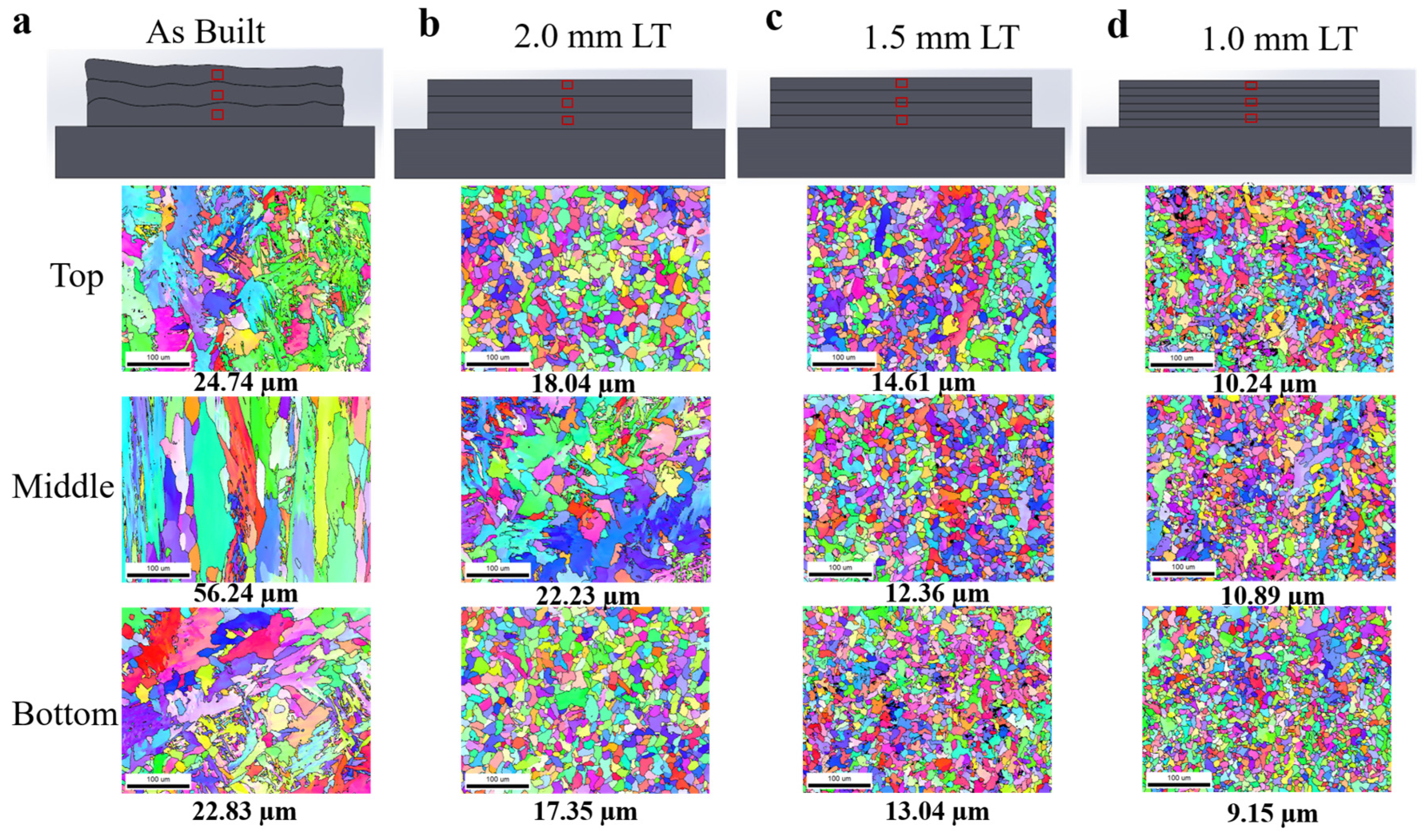
Figure 4 illustrates the grain evolution in WAAM-fabricated components under four different conditions: as-built, 2.0 mm layer thickness, 1.5 mm layer thickness, and 1.0 mm layer thickness, highlighting the impact of layer thickness by interlayer machining on grain size distribution. In the as-built WAAM condition, the grain structure varies across the build height due to different thermal gradients and solidification conditions. In the bottom region (1st layer of deposition), rapid heat dissipation into the substrate leads to a mix of equiaxed and short columnar grains, with an average grain size of 22.83 µm. The middle region, subjected to repeated heat input from successive layers, experiences epitaxial growth, resulting in predominantly columnar grains with an average size of 56.24 µm. In the top region, where cooling rates are lower due to reduced thermal dissipation, the grains show a mix of equiaxed and columnar morphologies, averaging 24.74 µm. Interlayer machining in the samples, carried out via face milling with cutting and thrust forces of 524N and 340N, respectively, flattens the uneven WAAM-deposited surface and alters the grain structure. This process interrupts epitaxial columnar growth, and machining-induced plastic deformation, along with localized strains facilitates grain refinement through recrystallization. For a 2.0 mm layer thickness, the bottom region exhibits an average grain size of 17.35 µm, the middle region has 22.23 µm, and the top region shows 18.04 µm, demonstrating effective grain refinement compared to the as-built condition. Reducing the layer thickness to 1.5 mm by introducing more number of milling cycles further enhances grain refinement, with average grain sizes of 13.04 µm in the bottom, 12.36 µm in the middle, and 14.61 µm at the top. This reduction in thickness decreases the heat accumulation per layer, leading to better grain control. The most refined microstructure is observed at 1.0 mm layer thickness, where the bottom region achieves 9.15 µm, the middle 10.89 µm, and the top 10.24 µm, illustrating the significant influence of layer height on thermal history and grain structure. The primary reason for this refinement is that thinner layers allow for more effective heat dissipation and induce localized recrystallization due to plastic deformation from milling, promoting finer equiaxed grains throughout the build. The progressive reduction in layer thickness minimizes grain growth anisotropy and results in a more uniform microstructure with better mechanical properties.
A similar trend of grain size refinement with and without interlayer machining of the same material was observed by Rashid et al. [
34]. Chen et al. [
35] also reported the impact of interpass milling on grain refinement and various related mechanical properties for Titanium alloy, but the trend shows similar results.
3.2. Microhardness
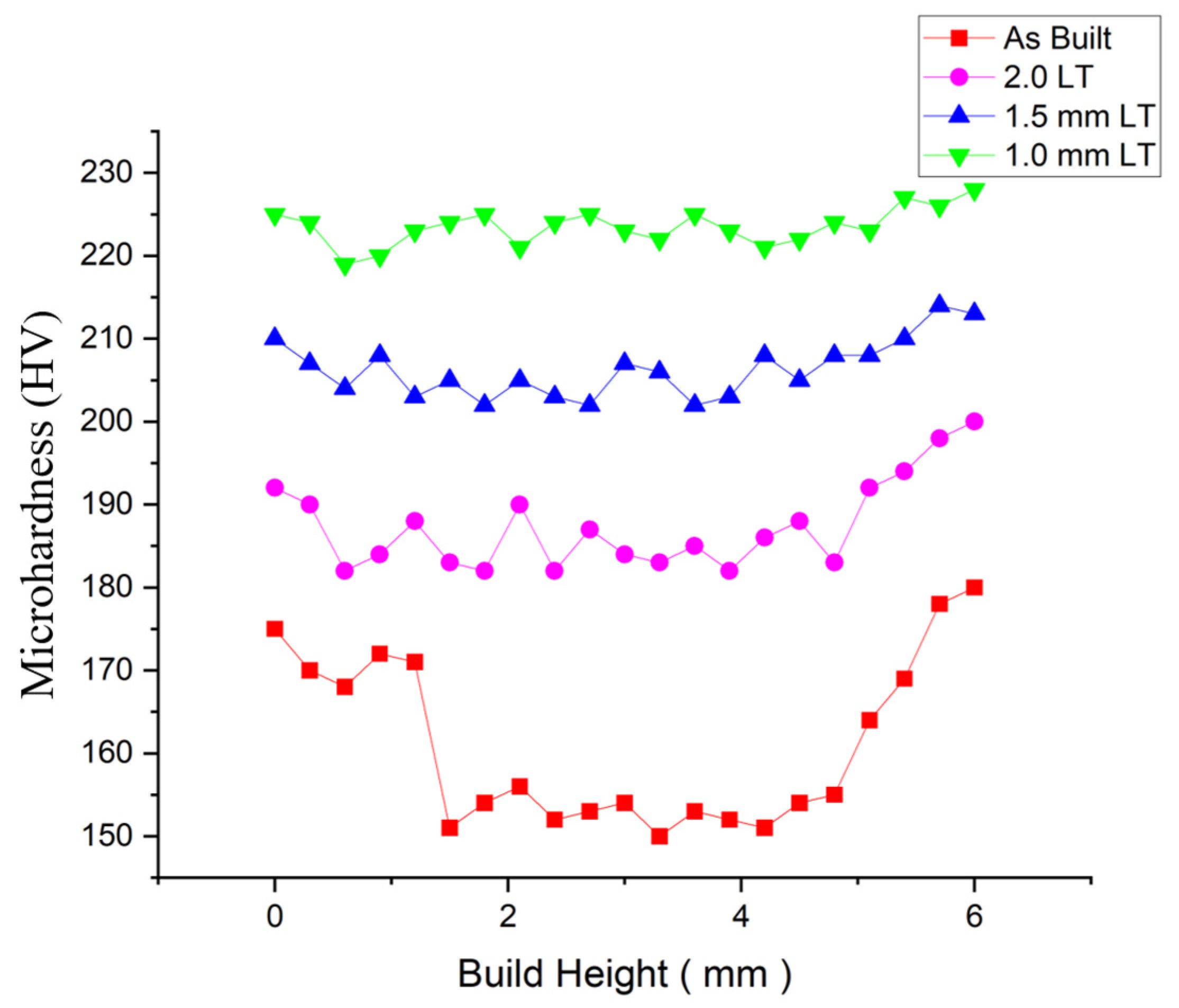
Figure 5 demonstrates the microhardness variation across different conditions with respect to build height. In the as-built condition (red squares), microhardness remains the lowest, fluctuating between 150 HV and 180 HV, due to coarser grain structures from thermal cycling. In the 2.0 mm layer thickness condition (pink circles), microhardness improves to a range of 175 HV to 195 HV, attributed to partial grain refinement induced by machining. The 1.5 mm layer thickness condition (blue triangles) exhibits further hardness enhancement, ranging between 200 HV and 215 HV, as more frequent interlayer machining promotes finer grain structures and increased work hardening. The 1.0 mm layer thickness condition (green inverted triangles) shows the highest and most stable microhardness, consistently between 215 HV and 230 HV, due to maximum grain refinement and recrystallization effects. The as-built condition shows lower hardness in the middle regions due to coarser dendritic structures, all machined conditions maintain a more stable hardness throughout the build height. The slight increase in hardness at the top may result from variations in cooling rate during deposition. This analysis confirms that interlayer machining significantly enhances hardness, with more frequent machining (lower layer thickness) leading to finer microstructures.
3.3. Stress-Strain Curves
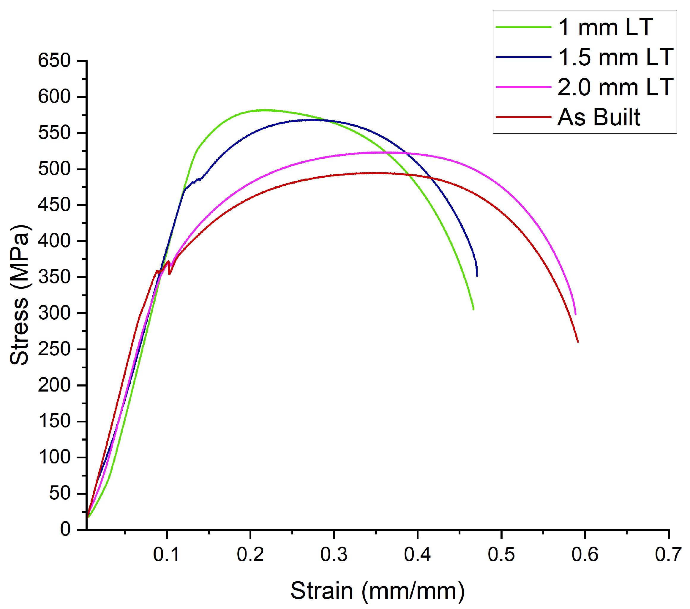
Figure 6 highlights the impact of interlayer machining (ILM) on the stress-strain maps of WAAM-fabricated samples, demonstrating a progressive increase in strength with decreasing layer thickness due to grain refinement and work hardening. The as-built condition (red curve) exhibits the lowest yield strength (~350 MPa) and ultimate tensile strength (~480 MPa) due to coarser columnar grains, though it retains moderate ductility (~0.55 mm/mm). The 2.0 mm layer thickness condition (pink) shows a slight improvement in strength (YS: ~370 MPa, UTS: ~510 MPa) and fracture strain (~0.58 mm/mm), attributed to partial grain refinement. The 1.5 mm layer thickness condition (blue curve) further enhances strength (YS: ~390 MPa, UTS: ~550 MPa) due to increased dislocation density, with a slight reduction in ductility (~0.52 mm/mm). The 1.0 mm layer thickness condition (green curve) achieves the highest strength (YS: ~400 MPa, UTS: ~600 MPa) due to maximum grain refinement and work hardening but exhibits a moderate drop in ductility (~0.48 mm/mm).
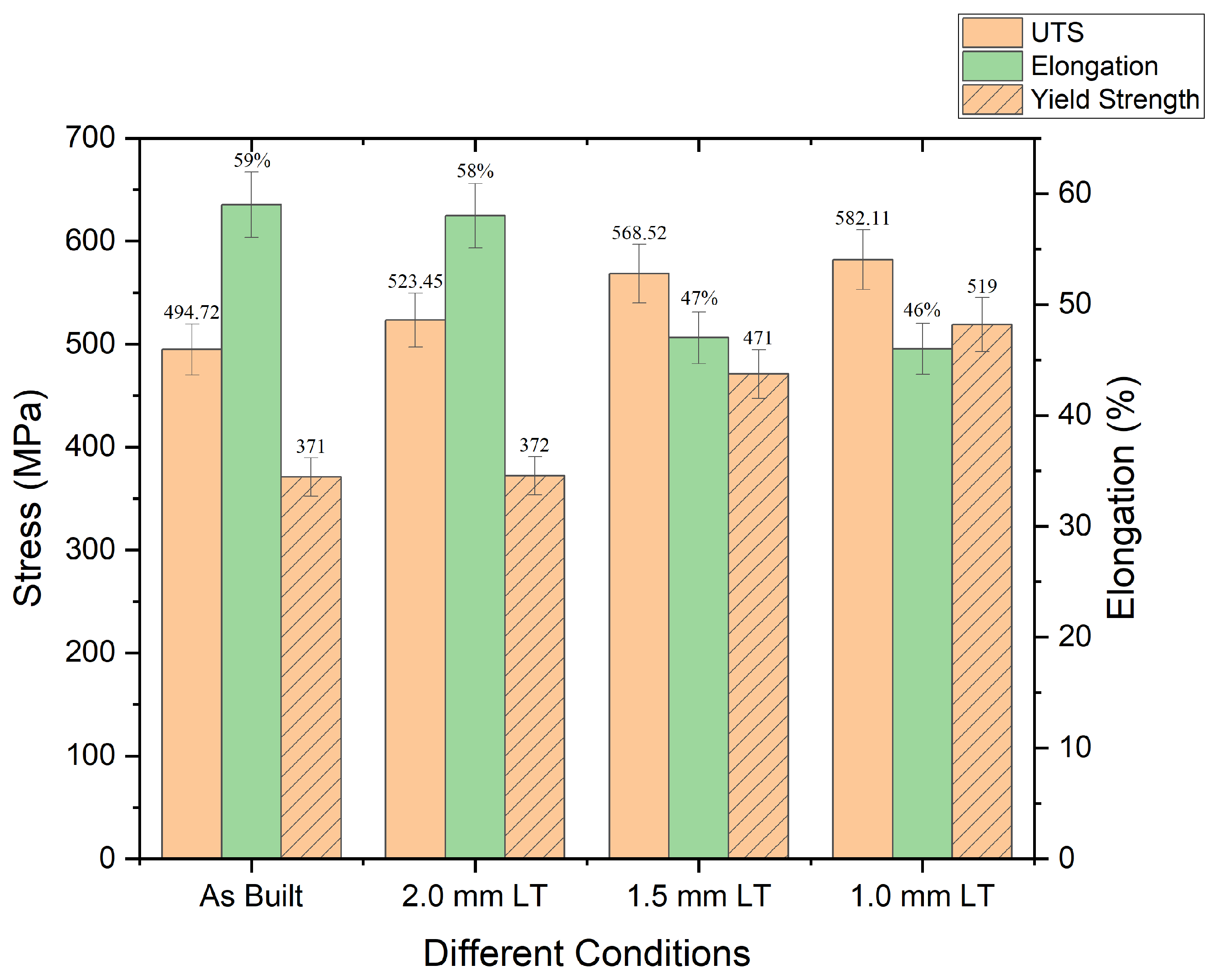
Figure 7 illustrates the variation in ultimate tensile strength (UTS), yield strength (YS), and elongation across different interlayer machining (ILM) conditions in WAAM-fabricated samples, highlighting the effect of grain refinement and residual stress reduction. The as-built condition exhibits the lowest YS (371 MPa) and UTS (494.72 MPa) due to the presence of coarse columnar grains, yet it retains the highest elongation (59%), benefiting from a more ductile microstructure. The 2.0 mm layer thickness condition slightly improves UTS (523.45 MPa) and YS (372 MPa), while elongation remains relatively high (58%) due to moderate grain refinement and stress relaxation. The 1.5 mm layer thickness condition shows a significant enhancement in YS (471 MPa) and UTS (568.52 MPa) as finer equiaxed grains and dislocation strengthening contribute to better mechanical properties, though elongation reduces to 47%. The 1.0 mm layer thickness condition achieves the highest UTS (582.11 MPa) and YS (519 MPa), indicating maximum strengthening from refined grains and work hardening, but elongation drops to 46%, suggesting a trade-off between strength and ductility
3.4. Residual Stress
The presence of non-uniform layer thickness during as-built conditions results in elevated residual stress compared to the case where a consistent layer thickness of 2 mm, 1.5 mm, and 1 mm is employed. This phenomenon primarily stems from variations in thermal gradients and cooling rates. As-built WAAM often leads to uneven cooling and significant residual stress within thicker layers, and a high value of residual stresses was observed in sample S1. By applying intermittent compressive forces to reduce the residual stress from the WAAM surface and redistribute internal stresses, promoting a consistent distribution. This leads to a reduction in residual stress as the number of machining passes increases, imparting compressive load. The reduction in residual stress enhances structural integrity and minimizes the risk of deformation or cracking.
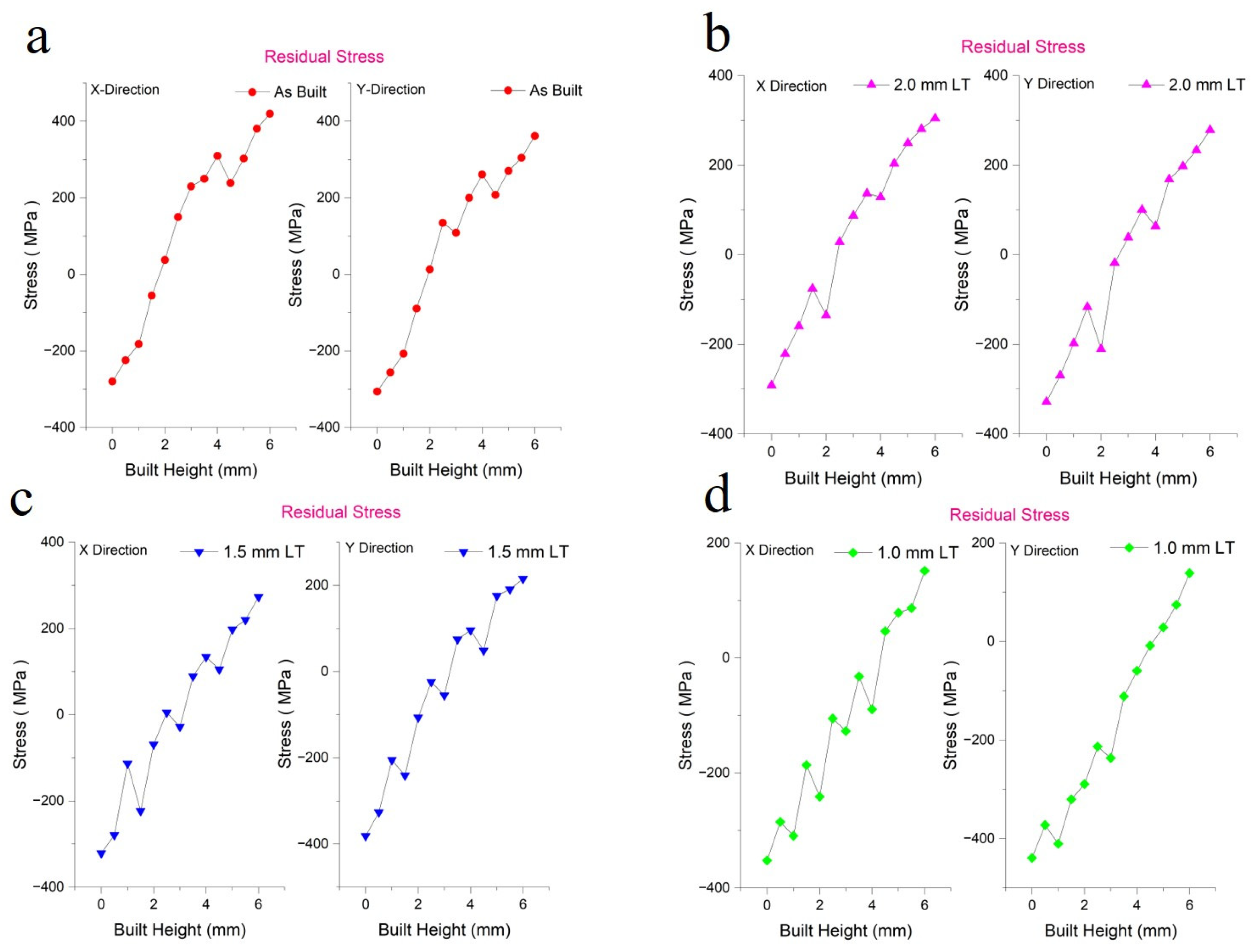
In
Figure 8, the graphs (a, b, c, and d) illustrate residual stress (in MPa) along the build height (in mm) in the X and Y directions under different conditions: (a) As-built, and (b-d) after successive machining with layer thicknesses of 2.0 mm, 1.5 mm, and 1.0 mm, respectively. The as-built condition (a) shows the highest residual stresses, which increase significantly along the build height. With successive machining (b-d), the magnitude of residual stresses progressively decreases as layer thickness reduces. This reduction correlates directly with material removal during machining, as the process eliminates surface and sub-surface layers where the most significant residual stresses are concentrated due to rapid cooling and solidification during WAAM. Machining redistributes the internal stress field more evenly, reduces stress peaks, and mitigates work hardening effects, while localized thermal or mechanical effects from machining may further contribute to stress relaxation. A comparison across different layer thicknesses shows that a 2.0 mm layer thickness (S2) results in moderate stress reduction compared to the as-built condition, while the sample with a 1.5 mm layer thickness (S3) provides further stress relaxation. The 1.0 mm layer thickness (S4) minimizes residual stresses, achieving the most uniform stress distribution among all conditions. Additionally, machining improves the surface finish, removing micro-cracks and makes the uniform deposition of subsequent layers on machined surface. These observations highlight that increased machining reduces residual stress by eliminating stress-concentrated layers, redistributing stresses, and mitigating thermal and mechanical effects, thereby enhancing the overall quality and mechanical performance of the WAAM-fabricated component.
The reduction in residual stress in both the X and Y directions follows a progressive trend as the layer thickness was decreased with more interlayer machining. Compared to the as-built condition, which exhibits the highest residual stress due to non-uniform layer thickness and uneven cooling, the 2 mm layer thickness condition achieves an approximate 22–25% reduction in residual stress due to improved thermal gradients and stress redistribution. Further reducing the layer thickness to 1.5 mm layer thickness results in a 38–42% reduction, as additional machining removes high-stress regions and redistributes internal stresses more effectively. The 1 mm layer thickness condition achieves the most significant stress reduction, approximately 55–60%, due to maximum material removal, improved stress relaxation, and uniform stress distribution. These results indicate that interlayer machining significantly reduces residual stress, minimizing deformation risks and enhancing the structural integrity of WAAM-fabricated components.
4. Conclusions
This study demonstrates the influence of varying layer thickness through interlayer machining in WAAM. As-built components exhibit uneven deposition, fostering coarse columnar grains that degrade hardness and strength. However, reducing layer thickness refines grains by restricting growth and inducing plastic deformation, thereby enhancing mechanical properties. Additionally, multi-insert interlayer machining applies compressive forces, effectively reducing residual stress and improving structural integrity.
Grain refinement at 1.0 mm layer thickness achieves reductions of 62.7% (Top), 77.6% (Middle), and 64.3% (Bottom), improving microstructural uniformity and mechanical properties through the Hall-Petch effect.
Microhardness increases from 150–180 HV (as-built) to 210–230 HV, marking a 40–43% improvement due to dislocation strengthening.
Tensile properties show significant enhancement: UTS rises from 494.72 MPa to 582.11 MPa (17.6% increase), and YS increases from 371 MPa to 471 MPa (26.9% increase) due to grain boundary strengthening and strain hardening.
Ductility trade-off: Elongation decreases from 59% to 46% (22% reduction) as restricted dislocation movement enhances strength at the expense of ductility.
Residual stress reduction of 55–60% at 1.0 mm layer thickness improves structural integrity by minimizing stress concentrations and reducing distortion or cracking risks.
While decreasing layer thickness enhances material properties, it increases production time and cost, necessitating a balance between mechanical improvements and manufacturing efficiency.
References
- Ayrilmis, N. Effect of Layer Thickness on Surface Properties of 3D Printed Materials Produced from Wood Flour / PLA Filament E Ff Ect of Layer Thickness on Surface Properties of 3D Printed Materials Produced from Wood Fl Our / PLA Fi Lament Nadir Ayrilmis. Polym Test 2021, 71, 163–166. [Google Scholar]
- Shergill, K.; Chen, Y.; Bull, S. An Investigation into the Layer Thickness Effect on the Mechanical Properties of Additively Manufactured Polymers: PLA and ABS. International Journal of Advanced Manufacturing Technology 2023, 126, 3651–3665. [Google Scholar] [CrossRef]
- Agrawal, A.P.; Kumar, V.; Kumar, J.; Paramasivam, P.; Dhanasekaran, S.; Prasad, L. An Investigation of Combined Effect of Infill Pattern, Density, and Layer Thickness on Mechanical Properties of 3D Printed ABS by Fused Filament Fabrication. Heliyon 2023, 9. [Google Scholar] [CrossRef]
- Gullane, A.; Murray, J.W.; Hyde, C.J.; Sankare, S.; Evirgen, A.; Clare, A.T. On the Use of Multiple Layer Thicknesses within Laser Powder Bed Fusion and the Effect on Mechanical Properties. Mater Des 2021, 212. [Google Scholar] [CrossRef]
- Hyer, H.C.; Petrie, C.M. Effect of Powder Layer Thickness on the Microstructural Development of Additively Manufactured SS316. J Manuf Process 2022, 76, 666–674. [Google Scholar] [CrossRef]
- Shah, A.; Gupta, N.K.; Aliyev, R.; Zeidler, H. Study of Various Process Parameters on Bead Penetration and Porosity in Wire Arc Additive Manufacturing (WAAM) of Copper Alloy Cu1897. Applied Sciences (Switzerland) 2024, 14. [Google Scholar] [CrossRef]
- Karade, S.R.; Siddhartha, S.; Gupta, N.K.; G, G.; Karunakaran, K.P.; Zeidler, H. Hybridization in Metal Wire Additive Manufacturing: A Case Study of an Impeller. Metals (Basel) 2025, 15. [Google Scholar] [CrossRef]
- Chernovol, N.; Lauwers, B.; van Rymenant, P. Development of Low-Cost Production Process for Prototype Components Based on Wire and Arc Additive Manufacturing (WAAM). Procedia CIRP 2020, 95, 60–65. [Google Scholar] [CrossRef]
- Ding, D.; Pan, Z.; Cuiuri, D.; Li, H. Wire-Feed Additive Manufacturing of Metal Components: Technologies, Developments and Future Interests. International Journal of Advanced Manufacturing Technology 2015, 81, 465–481. [Google Scholar] [CrossRef]
- Karunakaran, K.P.; Kamal Gupta, N.; Kumar Patel, A.; Rakeshkumar, K.; Ganesan, G.; Siddhartha; Sealy, M.; Bernard, A. Multi-Station Multi-Axis Hybrid Layered Manufacturing (MSMA-HLM). Manuf Lett 2022, 33, 630–639. [Google Scholar] [CrossRef]
- Zhou, N.; Peng, R.L.; Pettersson, R. Surface Integrity of 2304 Duplex Stainless Steel after Different Grinding Operations. J Mater Process Technol 2016, 229, 294–304. [Google Scholar] [CrossRef]
- Bekker, A.C.M.; Verlinden, J.C. Life Cycle Assessment of Wire + Arc Additive Manufacturing Compared to Green Sand Casting and CNC Milling in Stainless Steel. J Clean Prod 2018, 177, 438–447. [Google Scholar] [CrossRef]
- Sales, W.F.; Schoop, J.; da Silva, L.R.R.; Machado, Á.R.; Jawahir, I.S. A Review of Surface Integrity in Machining of Hardened Steels. J Manuf Process 2020, 58, 136–162. [Google Scholar] [CrossRef]
- Liao, Z.; la Monaca, A.; Murray, J.; Speidel, A.; Ushmaev, D.; Clare, A.; Axinte, D.; M’Saoubi, R. Surface Integrity in Metal Machining - Part I: Fundamentals of Surface Characteristics and Formation Mechanisms. Int J Mach Tools Manuf 2021, 162. [Google Scholar] [CrossRef]
- Cox, A.; Herbert, S.; Villain-Chastre, J.P.; Turner, S.; Jackson, M. The Effect of Machining and Induced Surface Deformation on the Fatigue Performance of a High Strength Metastable β Titanium Alloy. Int J Fatigue 2019, 124, 26–33. [Google Scholar] [CrossRef]
- Gupta, N.K.; Ganesan, G.; Siddhartha, S.; Karade, S.R.; Paul, A.K.; Dubey, S.; Ely, R.H.; Karunakaran, K.P. In Situ Pre-Heating in Wire Arc Additive Manufacturing: Design, Development, and Experimental Investigation on Residual Stresses and Metallurgical and Mechanical Properties. J Mater Eng Perform 2024. [Google Scholar] [CrossRef]
- Maity, M.; Tiwari, Y.; Manivannan, R.; Mukherjee, M. Influence of In-Situ Hammering on Microstructural, Mechanical and Residual Stress Behaviour of Inconel 718 during Wire Arc Additive Manufacturing. Progress in Additive Manufacturing 2024. [Google Scholar] [CrossRef]
- Gupta, N.K.; Ganesan, G.; Siddhartha, S.; Karade, S.R.; Singh, S.D.; Karunakaran, K.P. A Dual-Side Deposition Technique to Mitigate Deformation in Wire Arc Additive Manufacturing. Transactions of the Indian Institute of Metals 2024, 77, 3425–3434. [Google Scholar] [CrossRef]
- West, J.; Betters, E.; Schmitz, T. Limited-Constraint WAAM Fixture for Hybrid Manufacturing. Manuf Lett 2023, 37, 66–69. [Google Scholar] [CrossRef]
- Yang, X.; Zhang, B.; Bai, Q.; Kang, R.; Tang, J. Effect of Grain Size on Subsurface Characterization of Pure Iron Subjected to Orthogonal Cutting. International Journal of Advanced Manufacturing Technology 2022, 120, 5793–5806. [Google Scholar] [CrossRef]
- Brinksmeier, E.; Cammett, J.T.; König, W.; Leskovar, P.; Peters, J.; Tönshoff, H.K. Residual Stresses - Measurement and Causes in Machining Processes. CIRP Ann Manuf Technol 1982, 31, 491–510. [Google Scholar] [CrossRef]
- Arunachalam, R.M.; Mannan, M.A.; Spowage, A.C. Residual Stress and Surface Roughness When Facing Age Hardened Inconel 718 with CBN and Ceramic Cutting Tools. Int J Mach Tools Manuf 2004, 44, 879–887. [Google Scholar] [CrossRef]
- Pauza, J.; Rollett, A. Simulation Study of Hatch Spacing and Layer Thickness Effects on Microstructure in Laser Powder Bed Fusion Additive Manufacturing Using a Texture-Aware Solidification Potts Model. J Mater Eng Perform 2021, 30, 7007–7018. [Google Scholar] [CrossRef]
- Leicht, A.; Fischer, M.; Klement, U.; Nyborg, L.; Hryha, E. Increasing the Productivity of Laser Powder Bed Fusion for Stainless Steel 316L through Increased Layer Thickness. J Mater Eng Perform 2021, 30, 575–584. [Google Scholar] [CrossRef]
- Pan, Z.; Feng, Y.; Liang, S.Y. Material Microstructure Affected Machining: A Review. Manuf Rev (Les Ulis) 2017, 4. [Google Scholar] [CrossRef]
- Rajaguru, J.; Arunachalam, N. Investigation on Machining Induced Surface and Subsurface Modifications on the Stress Corrosion Crack Growth Behaviour of Super Duplex Stainless Steel. Corros Sci 2018, 141, 230–242. [Google Scholar] [CrossRef]
- Atmani, Z.; Haddag, B.; Nouari, M.; Zenasni, M. Multi-Physics Modelling in Machining OFHC Copper - Coupling of Microstructure-Based Flow Stress and Grain Refinement Models. Procedia CIRP 2015, 31, 545–550. [Google Scholar] [CrossRef]
- Bissey-Breton, S.; Vignal, V.; Herbst, F.; Coudert, J.B. Influence of Machining on the Microstructure, Mechanical Properties and Corrosion Behaviour of a Low Carbon Martensitic Stainless Steel. Procedia CIRP 2016, 46, 331–335. [Google Scholar] [CrossRef]
- Abboud, E.; Attia, H.; Shi, B.; Damir, A.; Thomson, V.; Mebrahtu, Y. Residual Stresses and Surface Integrity of Ti-Alloys during Finish Turning - Guidelines for Compressive Residual Stresses. Procedia CIRP 2016, 45, 55–58. [Google Scholar] [CrossRef]
- Derekar, K.S.; Ahmad, B.; Zhang, X.; Joshi, S.S.; Lawrence, J.; Xu, L.; Melton, G.; Addison, A. Effects of Process Variants on Residual Stresses in Wire Arc Additive Manufacturing of Aluminum Alloy 5183. Journal of Manufacturing Science and Engineering, Transactions of the ASME 2022, 144, 1–13. [Google Scholar] [CrossRef]
- Queguineur, A.; Asadi, R.; Ostolaza, M.; Valente, E.H.; Nadimpalli, V.K.; Mohanty, G.; Hascoët, J.Y.; Ituarte, I.F. Wire Arc Additive Manufacturing of Thin and Thick Walls Made of Duplex Stainless Steel. International Journal of Advanced Manufacturing Technology 2023, 127, 381–400. [Google Scholar] [CrossRef]
- Gupta, Neel Kamal, G, Ganesan, Siddhartha, Karade Shahu, Mehta, Avinash Kumar, KP, Karunakaran Effect of Multiple Technologies on Minimizing the Residual Stresses in Additive Manufacturing. In Proceedings of the ICRS 11 - The 11th International Conference of Residual Stresses, SF2M; IJL, Mar 2022, Nancy, France.; 2022; Vol. hal-040150.
- Jacob, K.; Yadav, D.; Dixit, S.; Hohenwarter, A.; Jaya, B.N. High Pressure Torsion Processing of Maraging Steel 250: Microstructure and Mechanical Behaviour Evolution. Materials Science and Engineering: A 2021, 802, 140665. [Google Scholar] [CrossRef]
- Rashid, A.; Kota, A.; Boing, D.; Melkote, S.N. Effect of Interlayer Machining Interventions on the Geometric and Mechanical Properties of Wire Arc Directed Energy Deposition Parts. J Manuf Sci Eng 2024, 146. [Google Scholar] [CrossRef]
- Chen, C.; Feng, T.; Zhang, Y.; Ren, B.; Wang, H.; Zhao, X. Improvement of Microstructure and Mechanical Properties of TC4 Titanium Alloy GTAW Based Wire Arc Additive Manufacturing by Using Interpass Milling. Journal of Materials Research and Technology 2023, 27, 1428–1445. [Google Scholar] [CrossRef]
|
Disclaimer/Publisher’s Note: The statements, opinions and data contained in all publications are solely those of the individual author(s) and contributor(s) and not of MDPI and/or the editor(s). MDPI and/or the editor(s) disclaim responsibility for any injury to people or property resulting from any ideas, methods, instructions or products referred to in the content. |
© 2025 by the authors. Licensee MDPI, Basel, Switzerland. This article is an open access article distributed under the terms and conditions of the Creative Commons Attribution (CC BY) license (https://creativecommons.org/licenses/by/4.0/).