
Submitted:
29 December 2025
Posted:
30 December 2025
You are already at the latest version
Abstract
The continuously increasing power density of modern electronic devices poses a major challenge for thermal management, motivating the development of cooling technologies that exceed the limits of conventional heat sinks and heat pipes. Vapor chambers, which utilize highly efficient two-phase heat transfer within a sealed enclosure, have emerged as attractive solutions for high-heat-flux applications in compact systems. In this work, a three-dimensional multiphysics modeling framework is developed to investigate the thermal behavior of a small-scale copper--water vapor chamber under representative operating conditions. The model couples heat transfer in solid and fluid domains with laminar compressible vapor flow and Brinkman flow in a porous wick to capture conjugate heat transport, vapor redistribution, and wick-assisted liquid return. Phase-change effects are incorporated through energy-conserving boundary conditions at the liquid--vapor interface, avoiding explicit interface tracking while retaining the dominant latent-heat transport mechanism. Numerical simulations performed in COMSOL Multiphysics resolve temperature, velocity, and pressure fields within the vapor chamber, revealing strong in-plane heat spreading and reduced peak temperature relative to purely conductive transport. The results demonstrate an effective interfacial thermal conductivity significantly higher than that of the working fluid alone, highlighting the role of two-phase transport in enhancing thermal performance. The proposed modeling framework provides a computationally efficient and extensible tool for analyzing vapor chamber operation and guiding the design and optimization of advanced thermal management solutions for high-power electronic systems.
Keywords:
vapor chamber
; thermal management
; two-phase cooling
; porous media
; conjugate heat transfer
; COMSOL Multiphysics
; electronics cooling
1. Introduction
The continual push for higher computational performance in microelectronics has led to a pronounced increase in both power consumption and heat flux densities at the chip level, posing a critical challenge for reliable thermal management in compact devices. Elevated junction temperatures accelerate failure mechanisms, degrade performance, and reduce service life; consequently, conventional air-cooled heat sinks are often insufficient for current and emerging power levels [1,2].
Two-phase passive cooling devices, such as heat pipes and vapor chambers, have therefore attracted extensive attention because of their very high effective thermal conductivity and lack of moving parts [7,36,37]. A heat pipe primarily transports heat along its longitudinal axis, whereas a vapor chamber functions as a planar heat spreader that distributes heat quasi-isotropically from a localized hot spot to a larger condenser area. This is particularly advantageous for microprocessors with non-uniform heat generation and compact form factors.
The design of vapor chambers is inherently multidisciplinary, involving conjugate heat transfer, vapor and liquid transport, porous-media flow in wicks, and interfacial phase change. Several recent studies have reported complementary insights into thermal transport and evaporation phenomena in micro- and nanoscale systems using both numerical and molecular approaches [9,10,11,12,13]. While experiments are essential for device qualification, computational modeling plays a key role in design exploration by enabling parametric studies of geometry, materials, and operating conditions. Existing models range from simplified thermal-resistance networks to fully resolved CFD formulations [16,21,22]. However, many reduced-order models lack spatial resolution of internal fields, whereas high-fidelity multiphase CFD can be computationally intensive for routine design.
In this context, the present work develops a three-dimensional multiphysics model of a copper–water vapor chamber in COMSOL Multiphysics®. The model incorporates laminar compressible vapor flow, Brinkman flow in a porous wick, and conjugate heat transfer with latent heat effects represented through boundary conditions at the liquid–vapor interface. The main objectives are:
- to construct a computationally efficient yet physically representative 3D model of a vapor chamber using coupled flow and heat transfer physics;
- to quantify thermal spreading and peak temperature reduction under representative chip-level heating;
- to analyze internal temperature, velocity, and pressure fields for improved physical understanding; and
- to establish a modeling framework, with clearly stated assumptions, that can be extended for parametric studies involving geometry, wick properties, and working-fluid selection.
2. Methods and Materials
2.1. Model Geometry and Simplifications
A simplified 3D geometry representing the central body of a vapor chamber was constructed to reduce computational cost while retaining the dominant physics of two-phase heat spreading. The modeled dimensions are 10SImm × SI20mm × SI1mm. The assembly comprises three principal functional regions: (i) two solid copper plates forming the outer shell, (ii) porous copper wicks lining the inner walls, and (iii) a central cavity containing the working fluid in its vapor phase.
Owing to geometric symmetry about the y–z plane, only half of the chamber was modeled, thereby reducing the number of degrees of freedom. The overall geometry and layer arrangement used in the COMSOL model are illustrated in Figure 1.

Table 1.
Geometry and materials of the vapor chamber model.
| Quantity | Layer name | Material | Thickness (mm) |
| 2 | Copper shell | Copper (solid) | 0.3 |
| 2 | Wick | Porous copper (68% porosity) | 0.3 |
| 1 | Cavity | Water (vapor) | 0.4 |
A SI1mm×SI1mm region on the bottom copper plate serves as the heat source, representing a localized microprocessor hot spot. External fins and detailed air-side flow are not resolved explicitly. Instead, heat rejection at the condenser side is represented via an effective convective boundary condition (Section 2.3). This approach is common in compact device-level modeling when the focus is on internal vapor-chamber transport rather than detailed external aerothermal design.
2.2. Governing Equations
The steady-state behavior of the vapor chamber is governed by conservation of mass, momentum, and energy, solved using multiple physics interfaces in COMSOL.
2.2.1. Heat Transfer in Solids and Fluids
Energy conservation in each domain is written as
where is density, is specific heat capacity, is velocity, T is temperature, is heat flux, and Q is a volumetric heat source. The conductive heat flux follows Fourier’s law,
with k the thermal conductivity.
2.2.2. Laminar Flow in the Vapor Cavity
The vapor flow in the central cavity is assumed laminar and compressible. The governing equations are the steady-state Navier–Stokes equations:
where p is pressure, is dynamic viscosity, is the identity tensor, and denotes body forces (e.g., gravity).
2.2.3. Brinkman Flow in the Porous Wick
The porous wick is modeled using the Brinkman equations, which augment Darcy’s law with viscous shear terms:
where is porosity and is permeability. This formulation captures both Darcy drag and local viscous dissipation within the porous wick [32].
2.2.4. Effective Thermal Conductivity of the Wick
The effective thermal conductivity of a saturated porous wick is estimated using the Halpin–Tsai model:
where and denote the conductivities of the continuous (copper) and dispersed (water) phases, respectively, and is a shape factor related to pore morphology [33]. This provides a practical estimate for design-level modeling where detailed pore-scale reconstruction is not performed.
2.3. Multiphysics Couplings and Boundary Conditions
The physics interfaces are coupled through shared variables and explicit multiphysics features.
2.3.1. Nonisothermal Flow
The Nonisothermal Flow coupling links the Laminar Flow and Heat Transfer interfaces, ensuring that temperature-dependent fluid properties influence the velocity field and that convective transport contributes to the energy equation.
2.3.2. Heat Input and Phase-Change Treatment
A constant heat flux is applied to the SI1mm 2 source area on the bottom copper surface to represent localized chip heating. Phase change between the wick-supplied liquid and the vapor cavity is not resolved using explicit interface-tracking techniques such as Level Set or VOF. Instead, latent heat exchange is incorporated via energy-conserving boundary conditions at the wick–vapor interface, following the common engineering approach used in heat-pipe style models [7,36].
At this interface, evaporation and condensation appear as heat sinks or sources:
- evaporation: liquid absorbs heat to form vapor, acting as a local heat sink in the wick;Table 2. Material properties used in the COMSOL model.
Material Property Symbol Value Units Source Copper (solid) Density 8960 SIkg.m -3 [30] Copper (solid) Specific heat 385 SIJ.kg-1.K-1 [30] Copper (solid) Thermal conductivity k 400 SIW.m-1.K-1 [30] Water (liquid) Density 997 SIkg.m-3 [30] Water (liquid) Specific heat 4180 SIJ.kg-1.K-1 [30] Water (liquid) Thermal conductivity k 0.6 SIW.m-1.K-1 [30] Water (liquid) Dynamic viscosity SIPa.s [30] Water (vapor) Density 0.554 SIkg.m-3 [30] Water (vapor) Specific heat 2010 SIJ.kg-1.K-1 [30] Water (vapor) Thermal conductivity k 0.026 SIW.m-1.K-1 [30] Water (vapor) Dynamic viscosity SIPa.s [30] Porous wick Porosity 0.68 – assumed/design value Porous wick Permeability SIm2 estimated Porous wick Effective conductivity 64.02 SIW.m-1.K-1 from Eq. (6) - condensation: vapor releases heat upon liquefaction, acting as a local heat source at the condenser side.
The corresponding interfacial heat flux is
where is the phase-change mass flux and is the latent heat of vaporization. This boundary-based formulation captures the dominant energetic effect of phase change without resolving microscopic interface dynamics.
2.3.3. Convective Cooling and Wall Conditions
To represent air-side heat rejection at the condenser, a convective boundary condition is imposed on a designated condenser surface region with an effective heat transfer coefficient , representative of low-to-moderate forced convection conditions in compact electronics enclosures. All solid walls are treated as impermeable with no-slip conditions for both vapor and porous domains.
2.4. Mesh Configuration
A high-quality mesh is essential for capturing steep gradients in temperature and velocity near the wick–vapor interface. The mesh consists primarily of structured swept elements with a maximum element size of SI0.1mm, ensuring adequate resolution across layers. Boundary-layer elements are deployed adjacent to the wick–vapor interface to resolve near-wall gradients.
2.5. Solver Setup
The coupled nonlinear system is solved in steady state using COMSOL’s fully coupled stationary solver with the MUMPS direct linear solver. Convergence is declared when the relative residuals of all dependent variables fall below the specified tolerance. Mesh-independence tests confirm that further refinement produces negligible changes in peak temperature and the reported effective wick conductivity (Table 3).
3. Results and Discussion
3.1. Surface Temperature Distribution
The normalized surface temperature distribution is plotted in Figure 3. The hottest region is localized beneath the evaporator at the center of the bottom surface, while temperatures decrease toward the condenser region, confirming effective two-dimensional heat spreading enabled by the vapor chamber architecture.
Axial temperature values at representative positions between evaporator and condenser are given in Table 4. The profile shows a smooth monotonic decline from the evaporator toward the condenser, consistent with the expected operation of a planar two-phase heat spreader.
3.2. Thermal Circuit Interpretation
For design interpretation, an equivalent resistance network can be constructed to partition the overall temperature rise into (i) junction-to-chamber resistance, (ii) internal spreading resistance within the vapor chamber, and (iii) condenser-to-ambient resistance. Within the present modeling assumptions, the internal spreading contribution is reduced by the two-phase mechanism, which promotes quasi-isothermal behavior in the vapor region and distributes heat over a larger condenser area. The largest sensitivity is typically associated with the external convection boundary condition and the wick transport parameters (porosity and permeability), indicating that accurate specification of air-side conditions and wick properties is important for predictive design studies.
3.3. Effective Thermal Conductivity
The modeled average effective thermal conductivity at the wick region is . This value is substantially higher than that of water and far lower than bulk copper, reflecting the composite nature of the wick: copper ligaments provide high-conductivity pathways, while water-filled pores enable latent-heat-driven redistribution through evaporation and condensation.
3.4. Velocity Field and Phase-Change-Driven Flow
The velocity field shows elevated vapor speeds in the cavity, driven by pressure gradients associated with net evaporation at the evaporator and condensation at the condenser. Vapor transport is directed from the evaporator toward the condenser, consistent with the physical operation of vapor chambers. Within the porous wick, velocities remain small because of high flow resistance, but the capillary-driven liquid return is sufficient to resupply the evaporator region under the imposed heat load.
The transverse velocity profile across the cavity thickness is summarized in Table 5. The near-parabolic shape, with maximum speed around mid-height and vanishing velocities at the walls, is characteristic of laminar shear-dominated internal flow.
3.5. Pressure Distribution
The predicted pressure field shows a modest high-pressure zone near the evaporator and a gradual decrease toward the condenser. Although the absolute variations are small on an ambient-scale reference, the gradient is sufficient to drive vapor flow across the cavity. The pressure distribution on the cavity surface is plotted in Figure 4.
Pressure vs. axial position along the cavity is given in Table 6.
4. Conclusions
A three-dimensional multiphysics model of a copper–water vapor chamber has been developed in COMSOL Multiphysics® for electronics cooling applications. The model couples laminar compressible vapor flow, Brinkman flow in a porous wick, and conjugate heat transfer, with latent heat incorporated through energy-conserving interfacial boundary conditions.
The numerical results demonstrate strong in-plane thermal spreading and reduced peak temperature beneath the localized heat source compared with purely conductive transport. Internal fields indicate that net evaporation at the heated region establishes a pressure-driven vapor flow toward the condenser, while the porous wick provides a return pathway for liquid replenishment. The model predicts an effective wick conductivity on the order of SI64W.m-1.K-1, consistent with the expected intermediate behavior of a saturated porous composite.
The present modeling strategy provides a practical balance between physical fidelity and computational efficiency, making it suitable for design-oriented parametric studies involving geometry, wick properties, and boundary conditions. Future work will extend the framework to transient operation, higher heat fluxes, and more detailed phase-change kinetics and capillary-limit characterization.
References
- Bar-Cohen, A. Thermal management of microelectronics in the 21st century. Electronics Cooling 1999, 5, 14–21. [Google Scholar]
- Mahajan, R.; Chiu, C.-P.; Chrysler, G. Cooling a microprocessor chip. Proceedings of the IEEE 2006, 94, 1476–1486. [Google Scholar] [CrossRef]
- Tuckerman, D. B.; Pease, R. F. W. High-performance heat sinking for VLSI. IEEE Electron Device Letters 1981, 2, 126–129. [Google Scholar] [CrossRef]
- Ozisik, M. N. Heat Transfer: A Basic Approach; McGraw-Hill, 1985. [Google Scholar]
- Garimella, S. V. Advances in mesoscale thermal management technologies for microelectronics. Microelectronics Journal 2006, 37, 1165–1185. [Google Scholar] [CrossRef]
- Fedorov, A. G.; Viskanta, R. Three-dimensional conjugate heat transfer in the microchannel heat sink for electronic packaging. International Journal of Heat and Mass Transfer 2000, 43, 399–415. [Google Scholar] [CrossRef]
- Peterson, G. P. An Introduction to Heat Pipes: Modeling, Testing, and Applications; John Wiley & Sons, 1994. [Google Scholar]
- Kang, S. W.; Wu, S. C.; Chen, W. P. Experimental investigation of flat porous heat pipe for cooling electronics. Experimental Thermal and Fluid Science 2009, 33, 311–318. [Google Scholar]
- Hussain, M. A.; Yesudasan, S.; Chacko, S. Nanofluids for solar thermal collection and energy conversion. Preprints preprint article 2020. [Google Scholar]
- Yesudasan, S. The critical diameter for continuous evaporation is between 3 and 4 nm for hydrophilic nanopores. Langmuir 2022, 38, 6550–6560. [Google Scholar] [CrossRef]
- Yesudasan, S. “Thermal dynamics of heat pipes with sub-critical nanopores,” arXiv:2406.xxxxx [physics.flu-dyn], 2024, arXiv preprint.
- Mohammed, M. M.; Yesudasan, S. Molecular dynamics study on the properties of liquid water in confined nanopores: Structural, transport, and thermodynamic insights. Proc. ASEE Northeast Section Conf., 2025; pp. 1–7. [Google Scholar]
- Hotchandani, V.; Mathew, B.; Yesudasan, S.; Chacko, S. Thermo-hydraulic characteristics of novel MEMS heat sink. Microsyst. Technol. 2021, 27, 145–157. [Google Scholar] [CrossRef]
- Cotter, T. P. Theory of heat pipes; Los Alamos Scientific Laboratory: Los Alamos, NM, USA, Rep. LA-3246-MS, 1965. [Google Scholar]
- Hong, F. J.; Cheng, P.; Wu, H. S.; Li, H. Y. Development of a flat plate heat pipe with wickless inner grooves. Journal of Thermophysics and Heat Transfer 2009, 23, 830–835. [Google Scholar]
- Bulut, M.; Kandlikar, S. G.; Sozbir, N. A review of vapor chambers. Heat Transfer Engineering 2019, 40, 1551–1573. [Google Scholar] [CrossRef]
- Weibel, J. A.; Garimella, S. V. Recent advances in vapor chamber transport characterization for high-heat-flux applications. InterSociety Conf. on Thermal and Thermomechanical Phenomena in Electronic Systems (ITherm), 2013; pp. 1–13. [Google Scholar]
- Busse, C. A. Theory of the ultimate heat transfer limit of cylindrical heat pipes. International Journal of Heat and Mass Transfer 1973, 16, 169–186. [Google Scholar] [CrossRef]
- Narayanan, M. H. N.; Kandlikar, S. G.; Kaladgi, S. N. S. Heat transfer and fluid flow in heat pipes. Advances in Heat Transfer 2016, 48, 373–427. [Google Scholar]
- An, J. S.; Kim, J. H.; Lee, J. W.; Chang, Y. S. Thermal performance of a vapor chamber heat sink with hybrid wick structure. International Journal of Heat and Mass Transfer 2020, 149, 119159. [Google Scholar]
- Zuo, Z. J.; Faghri, A. A network thermodynamic analysis of the heat pipe. International Journal of Heat and Mass Transfer 1998, 41, 1473–1484. [Google Scholar] [CrossRef]
- Wen, S. W.; Xie, W. L.; Wong, T. N. A three-dimensional numerical model for a vapor-chamber heat sink. Journal of Electronic Packaging 2011, 133, 011008. [Google Scholar]
- Zhao, C. Y. Review on thermal transport in high porosity metal foams. Applied Thermal Engineering 2012, 42, 1–12. [Google Scholar]
- Qu, W.; Mudawar, I. Experimental and numerical study of pressure drop and heat transfer in a single-phase micro-channel heat sink. International Journal of Heat and Mass Transfer 2002, 45, 2549–2565. [Google Scholar] [CrossRef]
- COMSOL AB, COMSOL Multiphysics® User’s Guide, Version 6.2. 2023.
- COMSOL AB, CFD Module User’s Guide, Version 6.2. 2023.
- Vasiliev, L. L. Heat pipes in modern heat exchangers. Applied Thermal Engineering 2005, 25, 1–19. [Google Scholar] [CrossRef]
- Vadakkan, U.; Garimella, S. V.; Murthy, J. Y. Transport in flat heat pipes at high heat fluxes from multiple discrete sources. Journal of Heat Transfer 2004, 126, 347–354. [Google Scholar] [CrossRef]
- Wang, Y. X.; He, Y. L.; Tao, W. Q.; Zhao, C. Y. Numerical simulation of a vapor chamber with multi-artery wick structure. Numerical Heat Transfer, Part A: Applications 2018, 74, 1173–1193. [Google Scholar]
- COMSOL AB, Heat Transfer Module User’s Guide, Version 6.2. 2023.
- Fox, R. W.; McDonald, A. T.; Pritchard, G. Introduction to Fluid Mechanics, 8th ed.; John Wiley & Sons, 2011. [Google Scholar]
- Nield, D. A.; Bejan, A. Convection in Porous Media, 5th ed.; Springer, 2017. [Google Scholar]
- Halpin, J. C.; Kardos, J. L. The Halpin–Tsai equations: A review. Polymer Engineering & Science 1976, 16, 344–352. [Google Scholar]
- Murshed, S. M. S.; Nieto de Castro, C. A. A critical review of traditional and emerging techniques and fluids for electronics cooling. Renewable and Sustainable Energy Reviews 2017, 78, 821–833. [Google Scholar] [CrossRef]
- Maydanik, Y. F. Loop heat pipes. Applied Thermal Engineering 2005, 25, 635–657. [Google Scholar] [CrossRef]
- Faghri, A. Heat Pipe Science and Technology; Taylor & Francis, 1995. [Google Scholar]
- Dunn, P. D.; Reay, D. A. Heat Pipes, 5th ed.; Pergamon Press, 1994. [Google Scholar]
- Ma, H. B.; Peterson, G. P.; Lu, X. J. The influence of vapor-liquid interactions on the liquid pressure drop in triangular microgrooves. International Journal of Heat and Mass Transfer 1994, 37, 2211–2219. [Google Scholar] [CrossRef]
- Chen, C. L.; Jang, S. P.; Lai, C. Y. Thermal performance of flat vapor chamber with hybrid wick structure. International Journal of Heat and Mass Transfer 2017, 108, 1026–1035. [Google Scholar]
- Shukla, K. N. Heat pipe for aerospace applications—an overview. Journal of Electronics Cooling and Thermal Control 2015, 5, 1–14. [Google Scholar] [CrossRef]
- Lienhard, J. H., IV; Lienhard, J. H., V. A Heat Transfer Textbook, 5th ed.; Phlogiston Press, 2019. [Google Scholar]
- Patankar, S. V. Numerical Heat Transfer and Fluid Flow; Hemisphere Publishing Corporation, 1980. [Google Scholar]
- Versteeg, H. K.; Malalasekera, W. An Introduction to Computational Fluid Dynamics: The Finite Volume Method, 2nd ed.; Pearson Prentice Hall, 2007. [Google Scholar]
- Cao, Y.; Faghri, A.; Chang, W. S. A numerical analysis of phase-change problems including natural convection. Journal of Heat Transfer 1989, 111, 812–816. [Google Scholar] [CrossRef]
- Pratap, V. S.; Dhamneya, A. K.; Mishra, S. C. Numerical investigation of the thermal performance of a vapor chamber heat sink. International Journal of Thermal Sciences 2018, 132, 533–543. [Google Scholar]
Figure 1.
Schematic of the simplified vapor chamber assembly, including copper shell, porous wick, and central vapor cavity with representative evaporator and condenser regions.
Figure 1.
Schematic of the simplified vapor chamber assembly, including copper shell, porous wick, and central vapor cavity with representative evaporator and condenser regions.
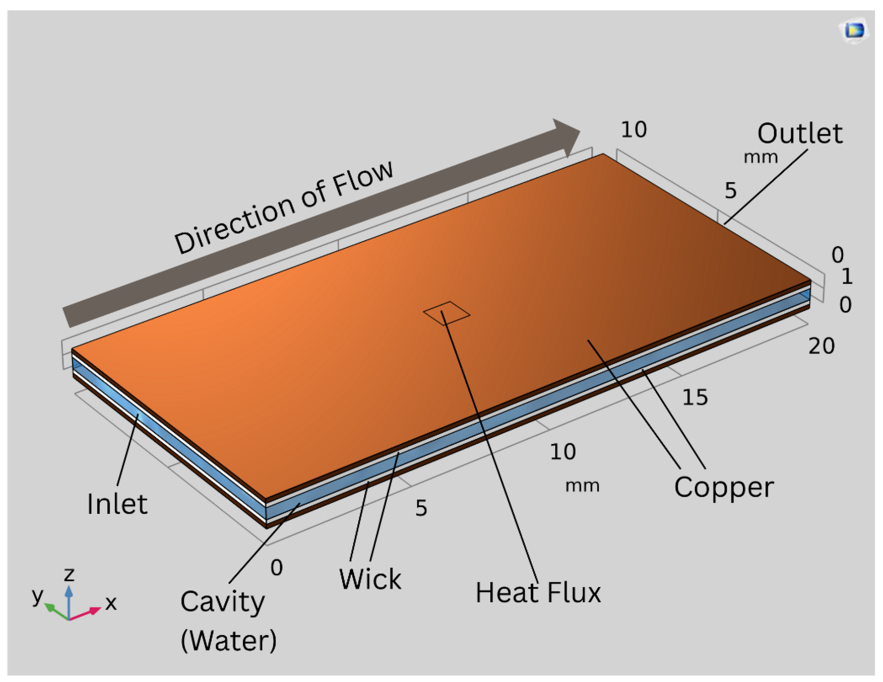
Figure 2.
Finite-element mesh used in the COMSOL model.
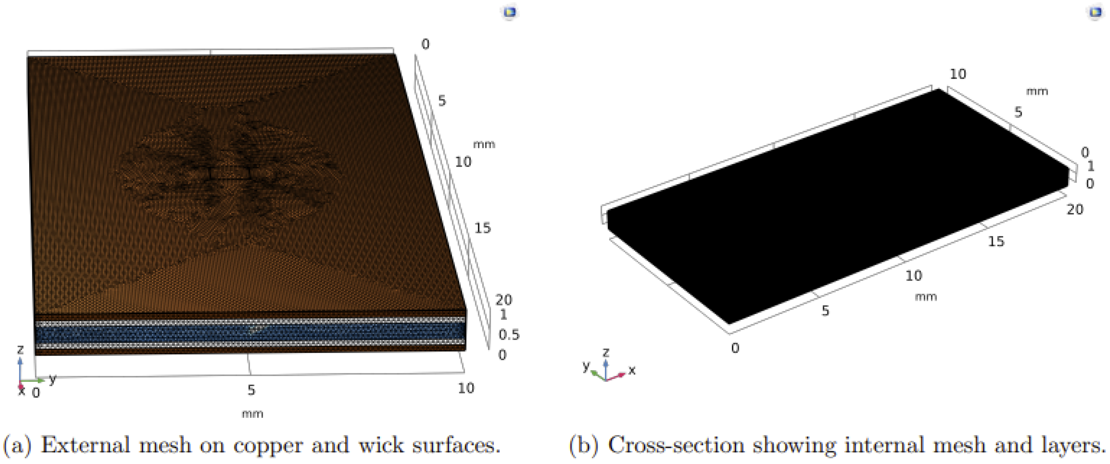
Figure 3.
Normalized temperature contours of the vapor chamber.
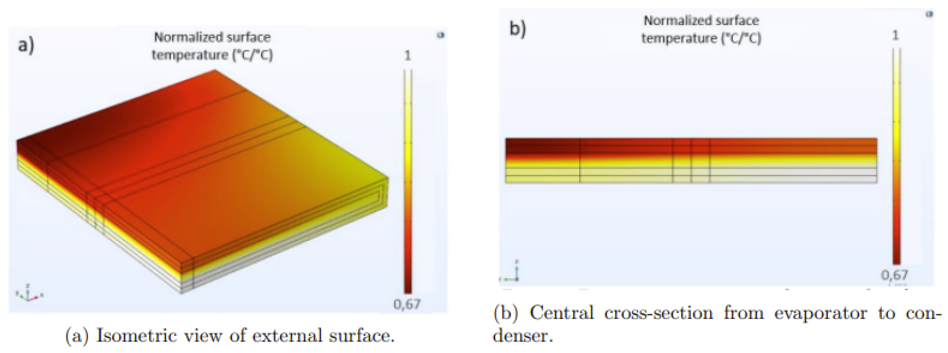
Figure 4.
Surface pressure field in the vapor cavity, showing a pressure gradient from evaporator to condenser.
Figure 4.
Surface pressure field in the vapor cavity, showing a pressure gradient from evaporator to condenser.
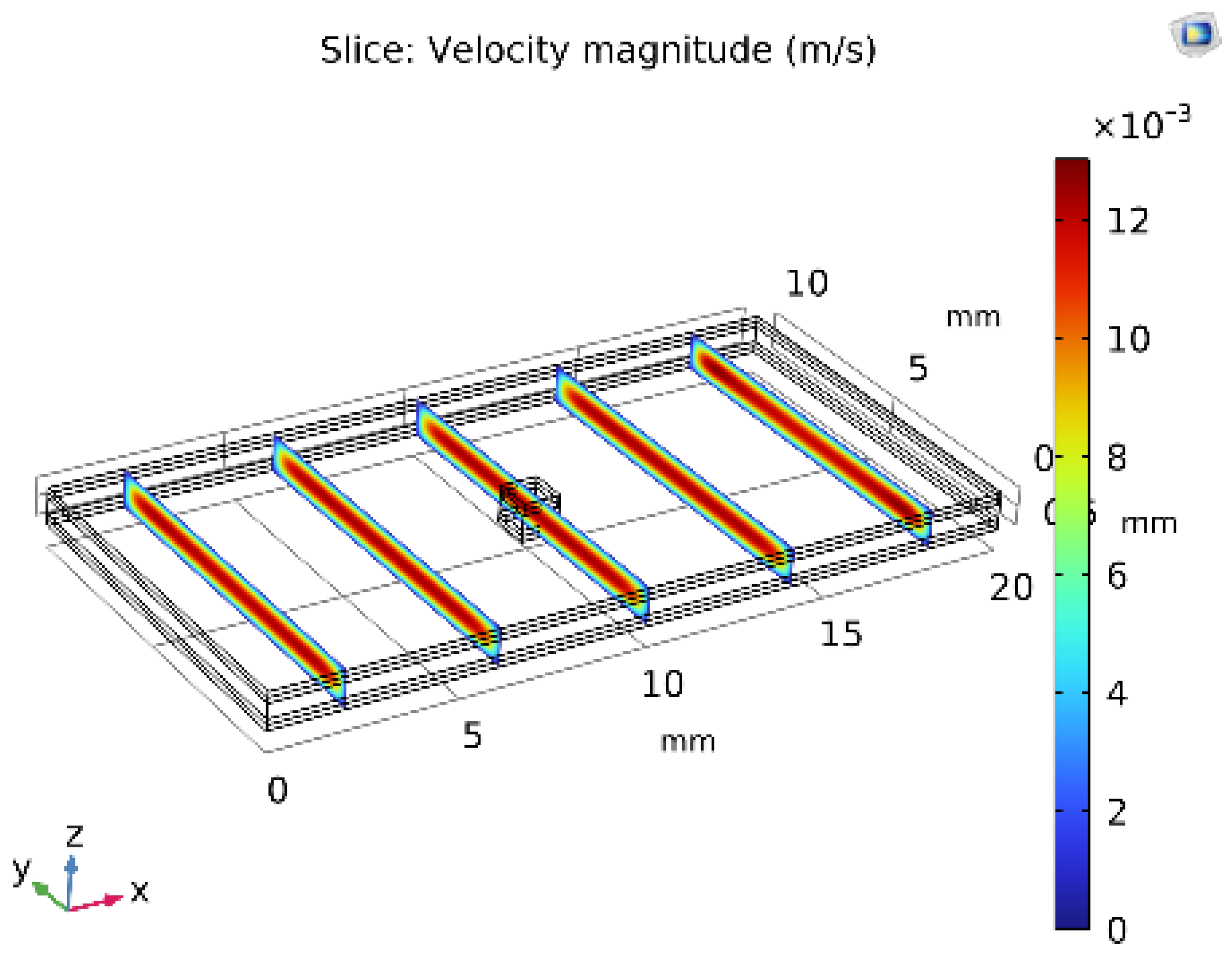
Table 3.
Mesh independence study for peak temperature and effective wick conductivity.
| Mesh | Elements () | (SIC) | (SIW.m-1.K-1) | Rel. change |
| Coarse | 0.25 | 86.2 | 62.1 | – |
| Medium | 0.50 | 85.3 | 63.5 | 1.0% / 2.3% |
| Fine | 1.00 | 85.0 | 64.0 | 0.4% / 0.8% |
| Very fine | 2.00 | 84.9 | 64.1 | 0.1% / 0.2% |
Table 4.
Representative temperature vs. position along the chamber centerline (simulation).
| Position (mm) | Temperature T (SIC) |
| 0 (Evaporator) | 85.0 |
| 5 | 80.2 |
| 10 | 75.5 |
| 15 | 72.3 |
| 20 (Condenser) | 70.0 |
Table 5.
Representative velocity profile across the vapor cavity height (simulation).
| Height from bottom (mm) | Velocity (m/s) |
| 0.0 | 0.00 |
| 0.1 | 0.25 |
| 0.2 | 0.45 |
| 0.3 | 0.50 |
| 0.4 | 0.40 |
| 0.5 | 0.20 |
| 0.6 | 0.00 |
Table 6.
Representative pressure vs. position in the vapor cavity (simulation).
| Position (mm) | Pressure (Pa) |
| 0 | 101325 |
| 5 | 101320 |
| 10 | 101315 |
| 15 | 101310 |
| 20 | 101305 |
Disclaimer/Publisher’s Note: The statements, opinions and data contained in all publications are solely those of the individual author(s) and contributor(s) and not of MDPI and/or the editor(s). MDPI and/or the editor(s) disclaim responsibility for any injury to people or property resulting from any ideas, methods, instructions or products referred to in the content. |
© 2025 by the authors. Licensee MDPI, Basel, Switzerland. This article is an open access article distributed under the terms and conditions of the Creative Commons Attribution (CC BY) license (http://creativecommons.org/licenses/by/4.0/).
Copyright: This open access article is published under a Creative Commons CC BY 4.0 license, which permit the free download, distribution, and reuse, provided that the author and preprint are cited in any reuse.


