
Submitted:
16 May 2025
Posted:
16 May 2025
You are already at the latest version
Abstract
Escalating heat flux densities in high-performance electronics necessitate superior thermal management. Pool boiling heat transfer, offering high heat removal capacity, was enhanced using binder jetting 3D-printed (BJ3DP) porous copper structures. Leveraging BJ3DP to create complex porous copper structures without chemical treatments—thereby enabling reliable utilization of phenomena like capillarity—this study enhanced pool boiling heat transfer. Therefore, in this study, three types of porous copper structures—Large Lattice, Small Lattice, and Staggered—were fabricated on pure copper substrates and tested via pool boiling of de-ionized and de-gassed water at atmospheric pressure.
Compared to a plain polished copper surface (plain surface), which exhibited a critical heat flux (CHF) of 782 kW/m² at a wall superheat of 18 K, the 3D-printed porous copper surfaces (sinterd plain surface) showed significantly improved CHF performance. In particular, the Staggered surface achieved a CHF of 2289 kW/m²—an enhancement of 193%—at a wall superheat of 25.9 K. Although CHF was not reached for the Large Lattice and Small Lattice structures, they attained maximum heat fluxes of 2071 kW/m² (165% higher at a wall superheat of 53.9 K) and 2291 kW/m² (193% higher at a wall superheat of 38.6 K), respectively.
These improvements are attributed to the formation of distinct vapor–liquid pathways within the porous structures, promoting rewetting of the heated surface through capillary action. This mechanism supports a highly efficient, self-sustaining boiling configuration. The porous surfaces also demonstrated a higher heat transfer coefficient (HTC), particularly at lower heat fluxes (≤750 kW/m²).
High-speed digital camera visualization provided further insights into the boiling phenomena. Overall, the findings demonstrate that these BJ3DP structured surfaces, through optimized liquid-vapor pathways and capillary-enhanced rewetting, offer significantly superior heat transfer performance compared to smooth surfaces, highlighting their potential for advanced thermal management.
Keywords:
pool boiling
; CHF
; HTC
; porous structure
; 3D printed porous
; heat exchanger
1. Introduction
Continuous development of high-performance electronics [1,2,3] has led to high heat flux densities, necessitating innovative cooling solutions to maintain operational reliability and safety while keeping systems compact [4] across diverse industrial applications. Pool boiling heat transfer is a critical aspect of thermal management, facilitating efficient heat dissipation due to its high heat removal capacity associated with both sensible and latent heat of vaporization. To achieve efficient cooling under higher thermal loads, attaining high critical heat flux (CHF) and heat transfer coefficient (HTC) values [5,6] is paramount.
Consequently, Pool boiling heat transfer characteristics have been extensively studied with considerable research focusing on various ways of modifying the characteristics of heat transfer surfaces including the use of Surface coating [7,8,9], bi-conductive surfaces [10] laser-textured surfaces [11,12] surface roughness effects [13], and other techniques. This pursuit has driven significant interest in modifying boiling surfaces at macro, micro, and nano scales [14,15,16]. The primary goals of these modifications are to significantly increase the surface area for heat transfer while facilitating effective and optimised liquid-vapour pathways, promote nucleation and improve bubble dynamics [17].
To achieve this, porous structures have been explored as a means to improve boiling heat transfer by creating separate paths for bubble nucleation sites and liquid supply thereby improving overall heat transfer through enhanced surface wettability [18] Lou et al., [19] numerically investigated the influence of porous media structural parameters such as porosity, pore density, height, thermal conductivity, and wettability. They determined that higher porosity (57.5% to 98.0%) can increase the CHF by an average of 3.75 times and the HTC by an average of 3.84 times compared to a plain surface.
Sun et al. [20] investigated hierarchical sintered porous structures combining copper mesh and porous columns. These structures exhibited enhanced capillary effects and increased CHF to 2422.9 kW/m², outperforming traditional sintered mesh by 43.7%. The addition of micro/nano coatings further increased nucleation sites, improving heat transfer coefficients, especially at lower heat fluxes. Pham et al., [21] showed that microporous structures, with larger pore diameters such as copper inverse opals, exhibit improved boiling performance due to better vapour permeability. Similarly, Wen et al. [22], using free-moving particles in packed structures, saw an increase in heat transfer coefficients by 126% compared to flat plates, highlighting the importance of particle size and arrangement.
Other studies on porous structures on heat transfer surfaces include that by Qian et al. [12] which showed that composite porous structures, such as 0.5 mm grid structures, greatly enhance CHF. They reported optimal critical heat transfer performance improvements of up to 10–27%, underscoring the significance of densely distributed pores that enable quick vapor bubble departure and foster effective heat transfer. Garivalis et al [23], experimented with porous Ti-6Al-4V coatings produced by cold spray additive manufacturing. They determined that these porous coatings, characterized by a honeycomb structure with thicknesses up to 3.0 mm, demonstrated increased HTC and CHF due to enhanced surface area and nucleation site density, indicating high potential for superior boiling heat transfer performance. In another study, Lee et al [24] developed a porous microgroove-structured surface via femtosecond laser processing of sintered copper surfaces to enhance pool boiling heat transfer. They determined that these surfaces activate multiple bubble nucleation sites, leading to a unique shift in heat flux curves and improved heat transfer coefficients. Furthermore, Liu et al [25] fabricated composite porous structures combining micropores with square channels using selective laser melting (SLM) technology and studied their boiling heat transfer performance. Micropores on the surface and inside the framework significantly increased the heat transfer coefficient, resulting in a 40% increase, particularly effective at high heat fluxes due to improved vapor–liquid separation
Ahmadi et al. [26] investigated the effect of sintered porous copper structure thickness on pool boiling heat transfer, also presenting the additional contribution of graphene coating to further enhancement. Their study highlighted enhanced heat transfer due to increased wetted area, nucleation sites, and improved thermal conductivity. Thinner porous structures exhibited optimal performance, achieving up to 161% enhancement compared to bare copper. Ho et al [27] experimentally investigated the heat transfer performance of micro-structured surfaces fabricated by the SLM technique. Moreover, a maximum HTC of 10.27 kW/m2K was obtained, corresponding to a 70% improvement compared to a plain surface. In contrast, the highest CHF value was 470.90 kW/m2, corresponding to a 76% enhancement compared with a plain surface. They attributed this improvement to the inherent surface grooves and cavities created by the laser melting process. Other porous surfaces studied include porous mesh and porous foam attachments [28,29,30], tunnels and re-entrant cavities[31], bead-packed porous layers [32], nanowire arrays [33],and others.
The size and geometry of structures play a critical role in enhancing boiling heat transfer. Both macro- and nanoscale surface structures have been investigated [34,35]. For example, Li et al. [36] developed a micro/nano structuring technique to create a three-tier hierarchical nano-engineered surface, demonstrating a significant CHF improvement (approximately 245% up to ≈400 W/cm²) compared to smooth copper surfaces, attributed to enhanced bubble dynamics. Kruse et al. [37] noted that porous micro/nanostructures enhance pool boiling heat transfer by promoting capillary wicking, leading to higher CHF values. This finding was echoed by Mani et al [11], who investigated laser-textured copper-grooved surfaces. Similarly, Lou et al. [38] created porous micro/nano structures using Laser Texture-Deposition, producing durable structures that significantly increase CHF and HTC.
Surface roughening has also been studied for heat transfer enhancement. Kim et al [39] studied the effect of surface roughness on pool boiling using copper surfaces polished with sandpapers of various grades. They observed a strong dependence and enhanced CHF performance with increasing surface roughness. The CHF achieved at the roughest surface (Ra = 2.36 µm) was1625 kw/m2, which was twice that achieved at the smoothest surface (Ra = 0.041 μm). They attributed the significant increase in CHF to the increased surface roughness and capillary wicking from the bulk liquid to dry areas. Song et al. [40], created rough surfaces using sandblasting with varying abrasive sizes. These surfaces significantly enhanced boiling performance, achieving up to 434.3% and 192.6% improvement in HTC and CHF, respectively, compared to a smooth silicon surface. Orman et al. [41]. used laser-induced micro-fins and surface roughness to triple the heat flux for water, demonstrating the effectiveness of precise surface modifications. Surface coating has also been studied [42,43,44,45]. Beyond structural modifications, researchers have also investigated depositing nanoparticles to modify the heating surface [46,47].
While the aforementioned research and numerous other studies on surface modification have demonstrated their effectiveness in improving pool boiling HTC and CHF [48], their widespread industrial adoption may be hindered by potentially high costs and complexities associated with multiple manufacturing steps [14,15]. 3D printing offers a simple, controllable, and cost-effective alternative for surface modification, potentially yielding similar or better heat transfer performance compared to surfaces produced by traditional methods such as machining, coating, and chemical processing.
Recent advancements in 3D printing technologies have enabled the fabrication of unique and complex porous structures. Consequently, several studies have experimentally investigated the heat transfer characteristics of these porous structures, particularly focusing on the influence of the unique geometries achievable only through 3D printing. For example, selective laser melting (SLM) 3D printing has received considerable interest. Re-entrant microchannel structures fabricated by SLM have shown significant improvements in boiling HTC, up to 330% in subcooled conditions [49]. Similarly, micro-structured surfaces fabricated by SLM 3D printing, particularly micro-fin surfaces, have demonstrated up to 63.5% improvement in heat transfer coefficients and higher CHF values than plain surfaces [50]. In another study of SLM 3D printing, Liu et al. [25] showed that rough surface samples, achieved by controlling the powder layer thickness during printing, exhibited a 40% increase in the average heat transfer coefficient compared to sandblasted samples. Similarly, Kuznetsov & Pavlenko [51] observed up to a six-fold enhancement in HTC with SLM 3D-printed capillary-porous coatings during nitrogen pool boiling. Other studies on 3D-printed heat transfer enhancement surfaces include that by Elkholy & Kempers [52] who reported an 80% increase in HTC at low heat fluxes and a 28% increase in CHF using 3D-printed polymer fixtures produced by fused filament fabrication. These studies highlight the potential of 3D printing in creating enhanced surface structures through careful design of surface geometries for thermal management applications.
3D-printed porous structures exhibit unique structural properties that facilitate improved heat transfer through their porosity and interconnected cavity networks. Different 3d manufacturing processes are used to create porous surfaces for heat transfer. However, to the authors' knowledge, very few studies have attempted to use BJ3DP to create such porous heat transfer surfaces. BJ3DP is an additive manufacturing (AM) process that offers several significant advantages over other Powder Bed Fusion (PBF) technologies, such as Selective Laser Melting (SLM) and Electron Beam Melting (EBM) [53], which are commonly used to create enhanced structures for heat transfer applications. Key benefits of BJ3DP include: its speed and cost-effectiveness for high-volume production, broad material compatibility due to its ambient processing temperature (handling difficult alloys), resulting in high part quality with reduced thermal stress and improved microstructure. Additionally, BJ3DP offers scalability for larger parts, high powder recyclability, excellent geometric capabilities for complex and fine features, and produces beneficial higher surface roughness, which is advantageous for applications like enhancing heat transfer by providing more nucleation sites[53]. This means BJ3DP offers the ability to create complex geometry structures without the need for additional mold manufacturing, reducing manufacturing costs. Leveraging BJ3DP metal porous structures effectively combines the advanced complex geometries achievable with 3D printing and the porous structure of the sintered material. This approach not only maximizes heat transfer efficiency in high-heat-flux environments but also positions BJ3DP technologies as a crucial solution for thermal management in high-performance electronics and other demanding applications.
The current study focuses on enhancing HTC and CHF using modified surfaces fabricated by BJ3DP, a process that combines additive manufacturing and sintering [54,55]. This technique involves layering powder, applying a binder, curing the binder, and then sintering to form the final part. This study examines the mechanisms of boiling performance enhancement for porous surfaces fabricated using BJ3DP and analyzes the impact on key parameters such as HTC, CHF, and the onset of nucleate boiling (ONB). Unlike conventional techniques, which often rely on chemical modification of surface wettability, the 3D-printed structures explored here exploit capillary forces to sustain very high heat fluxes, potentially surpassing traditional cooling solutions over an extended lifetime.
2. Experimental Methods
2.1. Test Piece Fabrication
The BJ3DP method was adopted for this study to create porous copper structures with various geometries: Sintered Plain, Large Lattice, Small Lattice, and Staggered. These structures were fabricated on a circular copper rod substrate. The aim is to improve pool boiling heat transfer by leveraging the unique properties of porous materials and the design flexibility offered by this additive manufacturing technique. A key advantage of BJ3DP is that it eliminates the need for support structures during printing, facilitates the creation of complex geometries, and offers rapid production [56].
The test pieces were manufactured through a multi-step process: First, a 3d model of the porous structure was geometrically designed using CAD software. This design was then prepared for slicing and processing by the printer. Thin layers of copper powder were spread onto a substrate, and a binder was selectively applied to define the structure's geometry, solidifying each layer. This layering and binding process was repeated to build the complete porous structure. The printed structure was then dried in an oven to cure the binder, ensuring its stability for subsequent steps. Loose, unbound copper powder was carefully removed. Binder removal (de-binding) was then performed in an oxidizing atmosphere. Finally, the structure was sintered in an inert atmosphere at high temperatures to fuse the copper particles, resulting in a dense, solid metallic porous component.
2.2. Test Piece Configuration
As mentioned above, four copper test pieces were prepared from a copper rod measuring 35 mm in diameter and 61.5 mm in length. The Sintered Plain test piece was fabricated from two uniform copper rod sections joined by a 20 mm thick sintered copper portion. This test piece was intended to confirm that the sintering process does not significantly alter the heat transfer characteristics of a uniform solid copper rod, implying that 3D-printed and sintered copper parts would exhibit similar heat transfer performance to solid copper.
The remaining three test pieces—the Large Lattice and Small Lattice, both featuring square lattice geometry, and the Staggered, featuring a carefully designed arrangement of larger and smaller square pores within a matrix positioned in a staggered pattern—were also based on the 35 mm diameter and 61.5 mm long copper rod. However, these test pieces incorporated a 2 mm thick porous copper section that was 3D-printed and sintered onto the substrate using the BJ3DP process, resulting in a final height of 63.5 mm for each. All test piece configurations are illustrated in Figure 1a-e.
2.3. Surface Characteristics of the BJ3DP Surfaces
Surface Roughness
The surface roughness of the BJ3DP test pieces was evaluated using a Keyence VK-X3000 laser microscope equipped with a white light interferometer. This non-contact measurement system provides high spatial resolution with a precision of 0.1 nm, enabling accurate detection of micro-scale surface variations that contact-based profilometers may not fully capture. Surface roughness measurements were conducted on a representative sample fabricated using the BJ3DP process. Figure 2 shows the measurement area. From this figure, ten distinct lines, labeled① through ⑩, were selected for detailed evaluation. The corresponding roughness values for these lines are summarized in Table 1.
The average arithmetic mean roughness (Sa) across the evaluated area was 9.14 μm, while the maximum height roughness (Sz) reached 108.5 μm. These results indicate a significantly rough surface characteristic of components produced by metal additive manufacturing processes like BJ3DP.
According to Simiao et al. test surfaces with higher roughness values within a reported range of Sa = 0.045 to 1.22 μm demonstrated improved heat transfer performance in pool boiling applications. While the average Sa measured in the present study (9.14 μm) exceeds this specific range cited by [57], the enhanced, complex surface topography produced via additive manufacturing is expected to promote bubble nucleation and vapor–liquid interactions significantly. The literature also suggests that the relationship between roughness and heat transfer enhancement depends on the specific surface preparation method. Consequently, despite exceeding the range from this particular study, the high and complex roughness achieved through BJ3DP is anticipated to positively impact boiling heat transfer efficiency by providing a high density of active nucleation sites.
Surface Characterisation via Scanning Electron Microscopy (SEM)
To investigate the surface of the 3D-printed copper porous structure at the microscale, a Scanning Electron Microscope (SEM) was used. Figure 3 presents SEM images of the test section surface. The image area corresponds to a plain surface fabricated through BJ3DP. The surface is rough and irregular, with finer details such as cavities created during manufacturing due to the sintered copper particles visible at this scale. These cavities are known to promote the formation of boiling nucleation sites, and a higher density of such cavities is desirable to increase the number of active nucleation sites, thereby enhancing boiling heat transfer performance. This characteristic unevenness is consistent with a porous layer formed by sintered powder. The size and distribution of these features are influenced by the size and morphology of the initial powder particles and the sintering parameters. Hence, the resultant porous layer formed by sintered particles leads to a surface rich in cavities, which act as nucleation sites, promoting bubble formation and ultimately enhancing the efficiency of boiling heat transfer. Accordingly, such cavity structures on the test pieces used in this study are expected to enhance heat transfer efficiency during boiling.
2.4. Experimental Apparatus
Figure 4 (a) and (b) show a photo and schematic diagram of the experimental setup used to study the pool boiling heat transfer performance of de-ionized and de-gassed water on the 3D-printed surfaces. The main components of the experiment consist of the boiling chamber, primary and secondary heating sections, a coil condenser, a boiling visualization system, and a data acquisition system.
The boiling chamber is made of cylindrical reinforced polycarbonate glass with a wall thickness of 3 mm, an outer diameter of 150 mm, and a height of 237 mm. The polycarbonate glass allows the boiling process inside the chamber to be visualized. Two-thirds of the vessel was filled with de-ionized and de-gassed water before each experiment.
The primary heating section consists of seven 600 W cartridge heaters installed at the bottom of a copper block to control the heat flux. The copper block is hollow at the top to fit the bottom part of the test piece and ensures negligible contact resistance between the test piece and the copper block. The block is insulated with glass wool to ensure that nearly all the heat generated by the heater is directed to the test section. The input power is regulated by two single-winding variac transformers (Bolt Sliders) powered by 200 V AC.
The secondary heater maintains the refrigerant saturation temperature, and four 250 W cartridge heaters are installed. These heaters are immersed in the refrigerant through protective tubes, and their output is controlled by a single small Bolt Slider (Single Winding Variac Transformer) powered by AC 100V. This ensures the refrigerant is kept at approximately the saturation temperature throughout the experiment.
Several K-type thermocouples were used in the experiment. The fluid saturation temperature (Tsat) was measured by a K-type thermocouple positioned at the top of the boiling chamber and immersed in the fluid. Three K-type thermocouples were embedded within the solid copper base of the test piece at different axial locations along the heat flow path to measure the temperature gradient. A linear regression based on these temperature measurements was used to determine the wall superheat (ΔTsat=Twall−Tsat) at the boiling surface. These thermocouples were precisely calibrated to minimize errors during temperature measurements.
A pressure gauge was installed on the flange at the top of the boiling chamber. An FP101A (Yokogawa Electric) absolute pressure gauge measured the vessel's pressure to maintain atmospheric pressure during experiments by controlling the condenser.
For visualization, a high-speed camera model Nova S16 (Photron), recording at 16,000 frames per second (fps) with a shutter speed of 1/200,000 seconds and a resolution of 1024 × 1024 pixels, was used to capture the boiling process. A lighting strobe on the camera side and a panel light (WTT 120120_TY-AI-08 from Nissin Electronics) on the opposite side were used as a backlight to ensure high image quality.
A spiral coil copper condenser with circulating coolant condensed the vapor to maintain atmospheric pressure. This also reduced evaporation and maintained the fluid level in the boiling chamber.
The data acquisition unit, MX100 (Yokogawa Electric), was used to monitor input power values and measure temperature and pressure data from the boiling setup. Temperature, pressure, and power data were continuously transmitted to a PC at a frequency of 1 Hz via the data acquisition unit, allowing the experimental apparatus to be constantly monitored.
A power supply and variac transformers (Bolt Sliders) were used to control heat inputs. The input power to the copper block was regulated by two variac transformers powered by 200 V AC, while the input power used to heat the fluid was controlled by a single small variac transformer powered by 100 V AC.
At the start of each experiment, the vapor phase above the liquid was de-gassed using a vacuum pump. Then, the fluid was brought to a boil using the auxiliary heaters and maintained in a boiling state for one hour before commencing data acquisition to ensure thermal equilibrium and remove dissolved gases.
2.5. Data Reduction
Figure 5(a) illustrates the test section setup and a representative temperature profile within the solid copper base. Figure 5(b) shows a schematic indicating the placement of sheathed K-type thermocouples (labeled ,) embedded along the central axis at different depths within the copper block to measure the temperature gradient during the pool boiling experiments.
Heat Flux Calculation: The heat flux (q′′) passing through the copper block and into the test surface was calculated using Fourier's Law of heat conduction, based on the measured temperature gradient within the solid copper base as in Equation 1.
Where is the thermal conductivity of copper and is the temperature gradient in the direction of heat flow (axial). The temperature gradient was determined by linear regression analysis of the temperatures measured by the embedded thermocouples ( ,) at their axial position.
Wall Superheat Determination: The temperature at the heating surface (Twall) was determined by extrapolating the linear temperature profile measured by the embedded thermocouples ( ,) to the position of the boiling surface (x=0). The wall superheat (ΔTsat) was then calculated as the difference between the extrapolated wall temperature and the measured saturation temperature of the fluid as shown in Equation 2.
Heat Transfer Coefficient (h): The heat transfer coefficient (h) was calculated using Newton's Law of Cooling as shown in Equation 3.
Where the calculated heat flux and is the determined wall superheat.
2.6. Reliability of Experimental Setup
To verify the reliability and overall integrity of the experimental apparatus, tests were carried out on the Plain (polished) and Sintered Plain test pieces using de-ionized and de-gassed water. The experimental results were compared with the widely applicable and extensively used Stephan-Abdelsalam correlation [58] for nucleate pool boiling in water. Proposed in 1980, this empirical correlation requires no tuning parameters for nucleate pool boiling in water. Proposed in 1980, this empirical correlation requires no tuning parameters [59,60,61]. contributing to its value and frequent citation [62,63,64]. Its adaptability and proven success in applied research underscore its significance in boiling heat transfer. The Stephan-Abdelsalam correlation for water on a plain surface is given by Equation 4 [58].
Where
Nusselt number (dimensionless heat transfer coefficient)
Heat flux
Bubble departure diameter
Thermal conductivity of liquid
Saturation temperature
Latent heat
Thermal diffusivity of liquid
Specific heat of liquid at constant pressure
Density of liquid
Density of vapour
The correlation implicitly accounts for the type of fluid through its properties) obtained from REFPROP steam tables. Experimental data provided The bubble departure diameter (d) is crucial for the Stephan-Abdelsalam correlation and was calculated using Equation 5 as provided in the model [58].
Experiments with the plain and sintered plain test pieces were conducted under the same conditions to confirm repeatability. Figure 6 shows the results of the two similar experiments, which match well with the predictions from the Stephan and Abdelsalam correlation, confirming the reliability and integrity of the experimental apparatus. Thus, the experimental setup was well fabricated, and the results are considered trustworthy and repeatable. Therefore, the thermal resistance between the solid copper rod (Plain) and the additively manufactured copper rod (Sintered Plain) is considered negligible, and the results are analyzed accordingly.
Important considerations for validation included the surface condition, since the Stephan-Abdelsalam correlation does not explicitly account for surface roughness. The surface of the plain samples was polished to a mirror finish using abrasive paper of different sizes, followed by a rubbing compound, achieving a surface roughness of approximately 1 μm. The second consideration was maintaining atmospheric pressure using the pressure gauge and condenser to ensure that the de-ionized and de-gassed water properties corresponded to the correct saturation temperature.
3. Results and Discussion
3.1. Boiling Curve Analysis
Figure 7 illustrates the pool boiling performance (Heat Flux vs. Wall Superheat) of the Sintered Plain, Large Lattice, Small Lattice, and Staggered surfaces in de-ionized and de-gassed water at atmospheric pressure, as represented by the boiling curves.
At the transition from free convection to nucleate boiling, the boiling curves for the Sintered Plain and Staggered surfaces exhibit a nearly linear increase in heat flux with increasing wall superheat, suggesting that the nucleate boiling regime governs heat transfer across the tested range until CHF is reached. In contrast, the boiling curves for the Large Lattice and Small Lattice take on a curvilinear, inverted U-shape, reflecting their transition into a high heat flux sustainment regime rather than exhibiting traditional CHF.
The structured surfaces (Large Lattice, Small Lattice, and Staggered) demonstrated significantly better heat transfer performance than the Sintered Plain surface. The Sintered Plain surface reached its Critical Heat Flux (CHF) at 782 kW/m2, while the Staggered surface reached a CHF of 2289 kW/m2. In both cases, CHF was identified by a sudden increase in wall temperature at increasing heat load, corroborated by direct observation of the boiling phenomenon.
Notably, traditional CHF behavior, characterized by a sharp decline in heat flux after the peak, was not observed for the Large Lattice or Small Lattice surfaces within the tested range. Instead, these surfaces reached peak heat fluxes of 2071 kW/m2 and 2291 kW/m2, respectively, followed by a gradual decline in heat flux with further increases in wall superheat. This behavior deviates from the typical boiling curve where heat flux sharply declines after CHF, suggesting unique mechanisms that sustain high heat fluxes without reaching a catastrophic dry out leading to traditional CHF.
3.2. Heat Transfer Coefficient Analysis
Figure 8 presents the Heat Transfer Coefficient (HTC) as a function of heat flux for all surfaces. All surfaces showed a general increasing trend in HTC, particularly in the low heat flux region (≤ 750 kW/m2). Consistent with the boiling curves (Figure 7), the HTC of the Large Lattice, Small Lattice, and Staggered surfaces was significantly higher than that of the Sintered Plain throughout the range of heat fluxes.
The Sintered Plain surface exhibited an increasing HTC trend up to its maximum HTC of 43.34 kW/m2·K, corresponding to its CHF of 782 kW/m2 at a wall superheat of 18.03 K. The Staggered surface showed a rapid increase in HTC at low heat fluxes, followed by a more gradual increase. Its peak HTC of 88.53 kW/m2·K was achieved at its CHF of 2289 kW/m2 at a wall superheat of 25.85 K.
The Large Lattice and Small Lattice surfaces showed a rapid growth in HTC within the low to medium heat flux region, reaching their highest HTC values early in this range. However, the HTC then decreased or flattened as the heat flux continued to increase towards their peak heat fluxes. The Small Lattice reached a peak HTC of 95.62 kW/m2.K at a heat flux of 272.72 kW/m2 and a corresponding wall superheat of 2.85 K. Its HTC was 59.27 kW/m2.K at the maximum heat flux achieved of 2291 kW/m2 at a wall superheat of 38.64 K. Similarly, the Large Lattice reached its highest HTC of 133.41 kW/m2.K at a heat flux of 513.97 kW/m2 and a corresponding wall superheat of 3.85 K. However, the HTC decreased to 38.4 kW/m2.K at its maximum achieved heat flux of 2071 kW/m2 at a wall superheat of 53.94 K.
The observed decrease or flattening of HTC for the lattice structures at higher heat fluxes (beyond their peak HTC points) likely results from increased bubble merging and growth, leading to greater vapor coverage on the surface and increased thermal resistance. However, this did not trigger a boiling crisis or traditional CHF due to continuous rewetting of the surface.
Compared to the Sintered Plain surface, the 3D-printed porous structures of the Large Lattice, Small Lattice, and Staggered surfaces significantly enhance both HTC and CHF. The structured surfaces' effectiveness stems from their ability to manage bubble dynamics and liquid supply through separate liquid-vapor pathways that facilitate liquid penetration and promote bubble nucleation.
At low heat fluxes, enhanced nucleation site density on the porous parts of the Large Lattice, Small Lattice, and Staggered surfaces leads to more frequent bubble formation and departure, resulting in higher heat dissipation efficiency than the Sintered Plain. At these low heat fluxes, HTC was improved by up to 104.27% (approximately 2.04 times higher) for the Staggered surface, 120.64% (approximately 2.21 times higher) for the Small Lattice, and 207.82% (approximately 3.08 times higher) for the Large Lattice compared to the Sintered Plain surface. While the Large Lattice and Small Lattice structures excel at low heat fluxes by promoting nucleation and facilitating early bubble escape and liquid rewetting through capillary action, their HTC performance at higher heat fluxes is limited by increased bubble merging. However, their internal structure provides less resistance to bubble escape and enhances liquid replenishment through interconnected pathways, significantly delaying dry spot formation and preventing these surfaces from reaching a traditional CHF. This allows the Large Lattice and Small Lattice to sustain very high heat fluxes, albeit with increasing wall superheat and potentially lower HTC values than their peaks. The Small Lattice's flatter HTC trend at medium to high heat fluxes compared to the Large Lattice's decreasing trend might be related to its smaller pore size offering the highest capillary force and interconnected cavity structures, potentially offering more controlled vapor escape or better localized rewetting.
Differing from the likely uniform wettability of the Sintered Plain surface, the Staggered test piece, combining porous structures and potentially less-porous plain areas, may exhibit mixed wettability or a wettability gradient effect. This coupling of different surface characteristics is believed to contribute to its superior boiling heat transfer performance across a wide range of heat fluxes, including achieving a high CHF. The rapid initial increase in HTC for the Staggered surface at low heat flux is followed by a steadier rise, which could be attributed to the beneficial effects of this mixed wettability facilitating continuous rewetting as heat flux increases.
3.3. Heat Flux Regimes and Dominant Mechanisms
To understand the boiling phenomenon, particularly where heat transfer surfaces recorded higher heat fluxes without reaching the traditional CHF, we discuss the boiling heat transfer performance of the tested surfaces by dividing the data into three distinct heat flux regions: the Low Heat Flux Region (≤ 750 kW/m2), the Medium Heat Flux Region (> 750 kW/m2 and ≤ 2000 kW/m2), and the Super-High Heat Flux Region (> 2000 kW/m2). These regions represent different boiling regimes characterized by evolving bubble dynamics and dominant heat transfer mechanisms. Two key factors influencing performance across these regions are surface wettability (affected by surface roughness and capillary forces) and bubble formation and departure dynamics. Essentially, the heat flux regions correspond to increasing vapor generation rates.
- Low Heat Flux Region (≤750 kW/m²)
In this region, discrete bubble formation and departure play a critical role. On both plain and porous surfaces, bubble formation occurs at isolated nucleation sites where individual bubbles grow before departing. For enhanced surfaces, the key factor is not intrinsic surface wettability but rather the promotion of frequent bubble departure and effective rewetting. The structured porous surfaces of the Large Lattice, Small Lattice, and Staggered promoted earlier bubble incipience and enhanced nucleation, leading to more frequent and improved bubble departure with minimum resistance and allowing for better surface rewetting. Here, the primary heat transfer mechanisms are evaporation at the base of isolated bubbles and natural convection. The porous structures enhance heat transfer by increasing the density of active nucleation sites and maintaining good surface wettability through improved liquid access to the bubble base.
At the onset of nucleate boiling, the Sintered Plain surface exhibited higher wall superheat than the Large Lattice, Small Lattice, and Staggered. For instance, the onset of nucleate boiling on the Large Lattice and Small Lattice occurred at very low wall superheats (-0.1 K and -0.5 K, respectively), indicating highly effective nucleation sites provided by the porous structures. This contrasts with the Sintered Plain surface, which required a higher wall superheat to initiate and sustain bubble growth. The porous structures served as vapor traps and acted as effective nucleation sites for the Large Lattice, Small Lattice, and Staggered.
The Large Lattice and Small Lattice surfaces exhibited superior boiling heat transfer compared to the Sintered Plain and generally performed slightly better than the Staggered surface in the very low heat flux range. As the heat flux increased within this region, the Staggered surface achieved higher heat fluxes at lower wall superheat values than the other surfaces.
- Medium to High Heat Flux Region (> 750 kW/m² and ≤ 2000 kW/m²)
From approximately 750 kW/m2 to 2000 kW/m2, the boiling behavior transitions from isolated bubbles to more complex vapor structures, including vapor columns and mushroom-like formations, accompanied by increased bubble frequency and coalescence. Bubble growth accelerates significantly, making surface wettability and effective liquid replenishment critical to prevent dry spots.
The interconnected porous structures of the Large Lattice, Small Lattice, and Staggered surfaces were particularly effective in promoting capillary-driven liquid replenishment to the heat transfer surface. This capillary action facilitated liquid flow through separate liquid-vapor pathways within the structure to maintain wetted areas. While the Large Lattice and Small Lattice structures benefit from their 3d spatial connectivity, the Staggered surface demonstrates the best performance from around 1000 kW/m2. This suggests the specific geometry of the Staggered structure is highly effective in this range at facilitating liquid replenishment and delaying the onset of dry spots, thereby enhancing heat transfer. This region's main heat transfer mechanisms are driven by increased nucleation, regulated bubble evolution, and capillary action maintaining surface wettability and preventing drying.
- Super-High Heat Flux Region (> 2000 kW/m²)
At these extremely high heat fluxes, vapor dynamics become increasingly complex, involving significant local heat flux variations, potential hot spots, and a high risk of reaching the Critical Heat Flux (CHF) and transitioning to film boiling on conventional surfaces. Surface structure is critical in preventing this transition and sustaining ultrahigh heat fluxes by effectively managing vapor removal and liquid supply.
The Staggered surface eventually reached CHF within this high heat flux region and transitioned to film boiling. The delayed CHF for this test piece, compared to the Sintered Plain, was due to the enhanced mechanisms discussed in the medium-to-high flux region (improved liquid replenishment due to capillary forces).
However, a unique phenomenon was observed with the Large Lattice and Small Lattice structures: traditional CHF was not reached within the tested limits. Instead, high heat fluxes were obtained with increasing wall superheat, beyond which heat flux started to decline gradually. This phenomenon, which indicates a suppression of the catastrophic transition to film boiling, has not been widely reported in previous studies. The authors attribute this to the lattice's unique three-dimensional internal connectivity. It is believed that this structure effectively disrupts the formation of a stable vapor film near the heated surface by breaking up the rapidly growing vapor structures three-dimensionally. While the lattice structure successfully sustains high heat flux by avoiding film boiling, the sheer rate of vapor generation likely exceeds the capacity of complete vapor removal and local liquid replenishment through internal transport alone, leading to the observed continuous increase in wall superheat despite the sustained heat flux. In this region, surface characteristics are paramount, with porous structures preventing film boiling through complex bubble management and liquid transport, primarily driven by capillary action and local heat flux management.
3.4. Visualisation of Bubble Characteristics
As detailed in Section 2.4 Experimental Setup, the boiling process and associated bubble characteristics were captured using a high-speed camera. Videos were recorded at 16,000 frames per second (fps) with a shutter speed of 1/200,000 seconds and a 1024 × 1024 pixels resolution. Figure 9, Figure 10, Figure 11, Figure 12, Figure 13, Figure 14 and Figure 15 show representative images of the boiling process on the heat transfer surfaces of the four test pieces at different heat fluxes.
At a low heat flux of 50 kW/m² (Figure 9 (a)-(d)), isolated bubbles distributed uniformly across the heat transfer surfaces were observed on all test pieces. The Large Lattice, and Small Lattice surfaces exhibited a noticeably higher bubble density than the Sintered Plain. This increased density on the lattice structures can be attributed to bubbles nucleating preferentially within the interconnected porous cavities. In contrast, the Sintered Plain surface showed fewer active nucleation sites, consistent with requiring a much higher wall superheat to achieve significant bubble growth, as indicated by the boiling curves (Figure 7).
At a heat flux of 100 kW/m² (Figure 10 (a)-(d)), a larger number of nucleation sites were observed on the Large Lattice, Small Lattice, and Staggered surfaces. Bubble formation and departure were stable and frequent, indicating efficient heat dissipation. This vigorous bubble activity directly correlates with the rapid increase in the HTC observed for these structured surfaces in this low heat flux region (Figure 7). While the high HTC at this low flux is primarily driven by the increased density of active nucleation sites provided by the structures, capillary-driven liquid supply is a major contributing factor.
Figure 11 (a)-(d) shows the bubble characteristics at 250 kW/m². For the Large Lattice, Small Lattice, and Staggered, bubbles were observed to detach from the heat transfer surface and then coalesce into larger vapour structures above the heat transfer surface. The interconnected porous cavities of the heated surface facilitate adequate liquid replenishment through capillary forces, supporting this detachment-coalescence behaviour away from the surface. However, bubbles tended to merge at the heat transfer surface on the Sintered Plain before detaching, forming larger vapour slugs. These vapour slugs effectively isolate portions of the heated surface from the bulk liquid, hindering the rewetting of the heating surface.
At a heat flux of 500 kW/m² (Figure 12 (a)-(d), the Large Lattice, Small Lattice surfaces continued to show bubbles detaching from the surface before coalescing into vapour structures above it. The formation of more defined vapour columns was observed for the Staggered surface. While bubble formation on the Sintered Plain coalesced into large, stable vapour slugs that covered a significant portion of the heat transfer surface, isolating the bulk liquid from the heating surface. This extensive vapour blanketing on the Sintered Plain led to a significant increase in wall superheat, ultimately resulting in CHF for the Sintered Plain reaching around 782 kW/m², consistent with the boiling curve (Figure 7).
Figure 13 (a)-(c) displays bubble characteristics at a higher heat flux of 1000 kW/m² on the Large Lattice, Small Lattice, and Staggered surfaces. Bubbles on all three surfaces detached from the surface and coalesced into several slightly larger bubbles. Crucially, these coalesced bubbles did not form a continuous vapour film that covered the heat transfer surface. This indicated that the surface remained in contact with the bulk liquid, and liquid replenishment was sufficient, helping to maintain a lower wall superheat consistent with the boiling curve (Figure 7).
Moving to 2000 kW/m² (Figure 14 (a)-(c)), bubbles detaching from the Staggered surface coalesced on top of the heating surface, forming distinct vapour columns. While not entirely film boiling, these columns almost covered the surface, significantly hindering direct liquid contact and replenishment to the heated area due to the lack of separate liquid vapour pathways provided by the interconnected channels on the heat transfer surface. In contrast, bubbles on the Large Lattice, and Small Lattice surfaces were still observed coalescing after departure, forming several unstable vapour columns that tended to collapse within the bulk fluid rather than spreading laterally and covering the surface.
Figure 15 (a)-(c) shows the boiling behaviour leading to CHF and the state of the surfaces at very high heat fluxes. Figure 15 (a) shows the Staggered surface at its CHF, with the entire heat transfer surface completely covered by a stable vapour film, leading to the sudden surge in wall superheat characteristic of CHF. Figure 15 (a) and (b) show the Large Lattice, and Small Lattice surfaces, respectively, just before the experiment was stopped due to overheating the copper block. Bubbles coalesced into large mushroom-like clouds on these lattice surfaces that nearly covered the entire heat transfer surface. However, the visuals showed rapid bubble nucleation, growth, and expulsion cycles. This dynamic behaviour, combined with adequate liquid replenishment via capillary action, kept the heat transfer surface intermittently wetted, preventing the formation of a stable vapor film and thus suppressing the typical CHF phenomenon.
4. Conclusions
This study investigated the effect of three distinct porous structures with varying pore sizes and geometries, fabricated using Binder Jetting 3D printing, on pool boiling heat transfer performance. Experiments were conducted using de-ionized and de-gassed water at atmospheric pressure. The main conclusions from this study are as follows:
- Superior Performance of 3d-Printed Structures: The 3D-printed heat transfer surfaces consistently exhibited significantly better boiling heat transfer performance than the Sintered Plain surface, particularly notable in the low heat flux region.
- CHF and Peak Heat Fluxes:
- The Sintered Plain surface reached its CHF at 782 kW/m2 at a wall superheat of 18.03 K.
- The Staggered surface demonstrated a substantial enhancement in CHF, reaching 2289 kW/m2 at a wall superheat of 25.9 K, approximately 193% higher than the Sintered Plain CHF.
- Notably, traditional CHF behavior (characterized by a sharp heat flux drop) was not observed for the Large Lattice and Small Lattice structures within the tested range. Instead, these surfaces sustained high heat fluxes, reaching peak values of 2071 kW/m2 (at a wall superheat of 53.9 K) and 2291 kW/m2 (at a wall superheat of 38.6 K). These peak heat fluxes represent an increase of approximately 165% and 193%, respectively, over the Sintered Plain CHF.
- 3.
- HTC Performance:
- The Sintered Plain surface showed an increasing HTC trend up to its maximum of 43.34 kW/m2.K, corresponding to its CHF.
- The Staggered surface exhibited a rapid increase in HTC at low heat fluxes, reaching a peak of 88.53 kW/m2.K at its CHF of 2289 kW/m2.
- The Large Lattice and Small Lattice surfaces showed rapid HTC growth in the low to medium heat flux region, reaching their highest values early in this range. The Small Lattice peaked at 95.62 kW/m2.K at a heat flux of 272.72 kW/m2 (wall superheat 2.85 K), while the Large Lattice peaked at 133.41 kW/m2.K at 513.97 kW/m2 (wall superheat 3.85 K). Beyond these peaks, the HTC for the lattice structures decreased or flattened as heat flux increased towards their maximum sustained values (Small Lattice HTC was 59.27 kW/m2.K at 2291 kW/m2 heat flux; Large Lattice HTC was 38.4 kW/m2.K at 2071 kW/m2 heat flux).
- At low heat fluxes, the structured surfaces significantly enhanced HTC compared to the Sintered Plain: the Staggered surface resulted in an enhancement of up to 104.27% (approximately 2.04 times), the Small Lattice up to 120.64% (approximately 2.21 times), and the Large Lattice up to 207.82% (approximately 3.08 times).
- 4.
- Mechanisms for Enhanced Performance: The superior performance of the 3D-printed structures is attributed to their porous nature, which provides enhanced nucleation site density and facilitates effective bubble management. Interconnected porous cavities create separate pathways for liquid and vapor flow, with capillary forces crucial in replenishing liquid to the heated surface. This capillary action, combined with potential wettability gradients (particularly in the Staggered design), delays dryout and sustains high heat fluxes.
- 5.
- Implications: This study's findings demonstrate the significant potential of Binder Jetting 3D-printed porous structures for enhancing pool boiling heat transfer. These findings hold promise for the development of advanced thermal management systems and next-generation heat exchangers in a potentially cost-effective manner.
Future Work: Based on these findings, the following areas are suggested for future investigation:
- Experimental studies on the pool boiling heat transfer performance of 3D-printed structures with a wider range of geometries and pore sizes.
- Experimental investigation of these structures' pool boiling heat transfer performance using different refrigerants.
- Numerical simulations will be used to analyze and understand the various physical phenomena observed in this research.
Author Contributions
O.L.A.: Experiments, Data curation, Investigation, Formal analysis, Writing – original draft. F.N.: Preparation and characterisation of samples, Experiments, Methodology, Visualisation, and Validation. K.K.: Pool boiling Experiments, Data curation, Writing – review & editing. T.M.: Validation, Writing – review & editing. K.E: Conceptualised the initial idea for this research, Supervision, Resources, Writing – review & editing.
Acknowledgements
The authors are grateful for the help from Toshihiko Saiwai, Jun Kato and Kenji Orito for this study.
References
- C. Dang, L. Jia, and Q. Lu, ‘Investigation on thermal design of a rack with the pulsating heat pipe for cooling CPUs’, Appl. Therm. Eng., vol. 110, pp. 390–398, Jan. 2017. [CrossRef]
- K. Zhang, Z.-H. Liu, and B. Zheng, ‘A new 3d chip cooling technology using micro-channels thermosyphon with super-moist fluids and nanofluids’, Energy Convers. Manag., vol. 128, pp. 44–56, Nov. 2016. [CrossRef]
- C. Nadjahi, H. Louahlia, and S. Lemasson, ‘A review of thermal management and innovative cooling strategies for data center’, Sustain. Comput. Inform. Syst., vol. 19, pp. 14–28, Sep. 2018. [CrossRef]
- Z. Zhang, X. Wang, and Y. Yan, ‘A review of the state-of-the-art in electronic cooling’, E-Prime - Adv. Electr. Eng. Electron. Energy, vol. 1, p. 100009, 2021. [CrossRef]
- W. Xu, L. Tang, N. Zhao, K. Ouyang, X. He, and X. Liu, ‘Corrosive effect on saturated pool boiling heat transfer characteristics of metallic surfaces with hierarchical micro/nano structures’, Heliyon, vol. 10, no. 8, p. e29750, Apr. 2024. [CrossRef]
- H. Bian, C. Kurwitz, Z. Sun, K. Cheng, and K. Chen, ‘Enhanced nucleate boiling on 3D-printed micro-porous structured surface’, Appl. Therm. Eng., vol. 141, pp. 422–434, Aug. 2018. [CrossRef]
- A. Ranjan, A. Priy, I. Ahmad, M. Pathak, Mohd. K. Khan, and A. K. Keshri, ‘Heat Transfer Characteristics of Pool Boiling With Scalable Plasma-Sprayed Aluminum Coatings’, Langmuir, vol. 39, no. 18, pp. 6337–6354, 2023. [CrossRef]
- H. Mohammadi, H. Taghvaei, and A. Rabiee, ‘Plasma Deposition of a Stable SiOx-like Layer on Copper Surface for Enhanced Pool Boiling Heat Transfer Performance: A Combination of Microstructures and Wetting Properties’, Plasma Process. Polym., vol. 18, no. 4, 2021. [CrossRef]
- N. Thangavelu, S. K. Duraisamy, and V. Devarajan, ‘Influence of TiO2 thin film on critical heat flux and performance enhancement of pool boiling at atmospheric pressure’, Proc. Inst. Mech. Eng. Part C, vol. 237, no. 13, pp. 3073–3085, Jul. 2023. [CrossRef]
- L. Tang, X. Liu, W. Xu, and L. Tang, ‘Pool Boiling Heat Transfer Enhancement Using Bi-Conductive Surfaces’, in ICONE31, Volume 6: Thermal-Hydraulics and Safety Analysis, Aug. 2024. [CrossRef]
- D. Mani, S. Suresh, H. M. Ali, and U. K. Ganesan, ‘Investigation to Improve the Pool Boiling Heat Transfer Characteristics Using Laser-Textured Copper-Grooved Surfaces’, Int. J. Photoenergy, vol. 2020, pp. 1–8, 2020. [CrossRef]
- B. Qian, H. Fan, J. Zhang, G. Liu, and P. Li, ‘Heat Exchanging Grid Structures Based on Laser-Based Powder Bed Fusion: Formation Process and Boiling Heat Transfer Performance’, Energies, vol. 15, no. 5, p. 1779, 2022. [CrossRef]
- B. M. Ali, ‘An Experimental Study of Heat Transfer in Pool Boiling to Investigate the Effect of Surface Roughness on Critical Heat Flux’, ChemEngineering, vol. 8, no. 2, p. 44, Apr. 2024. [CrossRef]
- J. Pereira, R. R. d. Souza, A. L. N. Moreira, and A. Moita, ‘An Overview of Innovative Surface-Modification Routes for Pool Boiling Enhancement’, Micromachines, vol. 15, no. 3, p. 302, 2024. [CrossRef]
- J. Pereira, R. R. d. Souza, R. Lima, A. L. N. Moreira, and A. Moita, ‘An Overview of the Recent Advances in Pool Boiling Enhancement Materials, Structrure, and Devices’, Micromachines, vol. 15, no. 2, p. 281, 2024. [CrossRef]
- G. Liang and I. Mudawar, ‘Review of pool boiling enhancement by surface modification’, Int. J. Heat Mass Transf., vol. 128, pp. 892–933, Jan. 2019. [CrossRef]
- M. C. Vlachou, J. S. Lioumbas, and T. D. Karapantsios, ‘Heat Transfer Enhancement in Boiling Over Modified Surfaces: A Critical Review’, Interfacial Phenom. Heat Transf., vol. 3, no. 4, pp. 341–367, 2015. [CrossRef]
- H. Liu, J. Wang, Z. Gu, X. Fei, and L. Zhang, ‘Enhancement of pool boiling heat transfer using 3D-printed groove structure’, Int. J. Heat Mass Transf., vol. 183, p. 122155, Feb. 2022. [CrossRef]
- Q. Lou, Z. Zhao, S. He, and L. Li, ‘Numerical investigation on the influence of porous media structural parameters on pool boiling heat transfer performance’, Phys. Fluids, vol. 36, no. 10, p. 103308, Oct. 2024. [CrossRef]
- Y. Sun et al., ‘Hierarchical sintered porous surfaces with enhanced pool boiling heat transfer performance for high-power cooling applications’, Appl. Therm. Eng., vol. 249, p. 123368, Jul. 2024. [CrossRef]
- Q. N. Pham, S. Zhang, L. Cheng-Hui, S. Hao, and Y. Won, ‘Boiling Heat Transfer Performance of Three-dimensionally Ordered Microporous Copper with Modulated Pore Diameters’, in 2018 17th IEEE Intersociety Conference on Thermal and Thermomechanical Phenomena in Electronic Systems (ITherm), Jun. 2018, pp. 1–6. [CrossRef]
- M.-Y. Wen, K.-J. Jang, and C.-Y. Ho, ‘Pool boiling heat transfer of de-ionized and de-gassed water in packed-perforated copper beads’, Heat Mass Transf., vol. 52, no. 11, pp. 2447–2457, Nov. 2016. [CrossRef]
- A. I. Garivalis, Y. Chen, E. Shatskiy, A. Robinson, P. D. Marco, and R. Lupoi, ‘Enhanced Pool Boiling Heat Transfer with Porous Ti-6Al-4V-Coatings Produced by Cold Spray Metal Additive Manufacturing’, J. Phys. Conf. Ser., vol. 2766, no. 1, p. 012130, May 2024. [CrossRef]
- S. Lee, Y. Kim, H. Ki, and J. Lee, ‘Femtosecond laser-treated copper sintering surface to enhance pool boiling heat transfer’, Int. Commun. Heat Mass Transf., vol. 152, p. 107270, Mar. 2024. [CrossRef]
- H. Liu, Z. Gu, and J. Liang, ‘Study on Boiling Heat Transfer Characteristics of Composite Porous Structure Fabricated by Selective Laser Melting’, Materials, vol. 16, no. 19, p. 6391, 2023. [CrossRef]
- V. E. Ahmadi et al., ‘Graphene-coated sintered porous copper surfaces for boiling heat transfer enhancement’, Carbon Trends, vol. 8, p. 100171, Jul. 2022. [CrossRef]
- J. Y. Ho, K. K. Wong, and K. C. Leong, ‘Saturated pool boiling of FC-72 from enhanced surfaces produced by Selective Laser Melting’, Int. J. Heat Mass Transf., vol. 99, pp. 107–121, Aug. 2016. [CrossRef]
- Z. G. Xu, Z. G. Qu, C. Y. Zhao, and W. Q. Tao, ‘Experimental correlation for pool boiling heat transfer on metallic foam surface and bubble cluster growth behavior on grooved array foam surface’, Int. J. Heat Mass Transf., vol. 77, pp. 1169–1182, Oct. 2014. [CrossRef]
- Z. G. Xu and C. Y. Zhao, ‘Pool boiling heat transfer of open-celled metal foams with V-shaped grooves for high pore densities’, Exp. Therm. Fluid Sci., vol. 52, pp. 128–138, Jan. 2014. [CrossRef]
- Z. G. Xu and C. Y. Zhao, ‘Experimental study on pool boiling heat transfer in gradient metal foams’, Int. J. Heat Mass Transf., vol. 85, pp. 824–829, Jun. 2015. [CrossRef]
- Y. Sun, G. Chen, S. Zhang, Y. Tang, J. Zeng, and W. Yuan, ‘Pool boiling performance and bubble dynamics on microgrooved surfaces with reentrant cavities’, Appl. Therm. Eng., vol. 125, pp. 432–442, Oct. 2017. [CrossRef]
- W. Chen and J. Wang, ‘Experiment Analysis of Pool Boiling Heat Transfer in Bead Packed Porous Layers’, Heat Transf.-Asian Res., vol. 45, no. 8, pp. 758–772, 2015. [CrossRef]
- D. I. Shim, G. Choi, N. Lee, T. Kim, B. S. Kim, and H. H. Cho, ‘Enhancement of Pool Boiling Heat Transfer Using Aligned Silicon Nanowire Arrays’, ACS Appl. Mater. Interfaces, vol. 9, no. 20, pp. 17595–17602, May 2017. [CrossRef]
- H. Zhao et al., ‘Microstructured Ceramic-Coated Carbon Nanotube Surfaces for High Heat Flux Pool Boiling’, ACS Appl. Nano Mater., vol. 2, no. 9, pp. 5538–5545, Sep. 2019. [CrossRef]
- W. Kalawa, T. M. Wójcik, and M. Piasecka, ‘Heat Transfer Research on Enhanced Heating Surfaces in Pool Boiling’, Epj Web Conf., vol. 143, p. 02048, 2017. [CrossRef]
- J. Li, W. Fu, B. Zhang, G. Zhu, and N. Miljkovic, ‘Ultrascalable Three-Tier Hierarchical Nanoengineered Surfaces for Optimized Boiling’, ACS Nano, vol. 13, no. 12, pp. 14080–14093, Dec. 2019. [CrossRef]
- C. Kruse et al., ‘Effects of Femtosecond Laser Surface Processed Nanoparticle Layers on Pool Boiling Heat Transfer Performance’, J. Therm. Sci. Eng. Appl., vol. 10, no. 3, 2018. [CrossRef]
- D. Lou et al., ‘Enhancement of pool boiling heat transfer by laser texture-deposition on copper surface’, Appl. Surf. Sci., vol. 661, p. 160015, Jul. 2024. [CrossRef]
- J. Kim, S. Jun, R. Laksnarain, and S. M. You, ‘Effect of surface roughness on pool boiling heat transfer at a heated surface having moderate wettability’, Int. J. Heat Mass Transf., vol. 101, pp. 992–1002, Oct. 2016. [CrossRef]
- Y. Song et al., ‘Enhancement of Boiling With Scalable Sandblasted Surfaces’, Acs Appl. Mater. Interfaces, vol. 14, no. 7, pp. 9788–9794, 2022. [CrossRef]
- Ł. J. Orman, N. Radek, J. Pietraszek, J. Wojtkowiak, and M. Szczepaniak, ‘Laser Treatment of Surfaces for Pool Boiling Heat Transfer Enhancement’, Materials, vol. 16, no. 4, p. 1365, Feb. 2023. [CrossRef]
- T. Nithyanandam and S. Duraisamy, ‘Experimental investigation of critical heat flux on SiO2 thin film deposited copper substrate in DI water at atmospheric pressure’, Therm. Sci., vol. 24, no. 1 Part B, pp. 549–556, 2020. [CrossRef]
- A. Jaikumar, A. Gupta, S. G. Kandlikar, C.-Y. Yang, and C.-Y. Su, ‘Scale effects of graphene and graphene oxide coatings on pool boiling enhancement mechanisms’, Int. J. Heat Mass Transf., vol. 109, pp. 357–366, Jun. 2017. [CrossRef]
- S. Sarangi, J. A. Weibel, and S. V. Garimella, ‘Effect of particle size on surface-coating enhancement of pool boiling heat transfer’, Int. J. Heat Mass Transf., vol. 81, pp. 103–113, Feb. 2015. [CrossRef]
- S. Sarangi, J. A. Weibel, and S. V. Garimella, ‘Quantitative Evaluation of the Dependence of Pool Boiling Heat Transfer Enhancement on Sintered Particle Coating Characteristics’, J. Heat Transf., vol. 139, no. 2, p. 021502, Feb. 2017. [CrossRef]
- E. Çiftçi and A. Sözen, ‘Heat transfer enhancement in pool boiling and condensation using h-BN/DCM and SiO2/DCM nanofluids: experimental and numerical comparison’, Int. J. Numer. Methods Heat Fluid Flow, vol. 31, no. 1, pp. 26–52, Jan. 2021. [CrossRef]
- A. A. Fahmy and Ali. A. A. Aziz, ‘Pool Boiling Heat Transfer From Aluminum Alloy Circular Surface Using Al2O3 and CuO Water Based Nano-Fluids’, Period. Polytech. Chem. Eng., vol. 64, no. 2, pp. 283–292, 2019. [CrossRef]
- S. K. Singh and D. Sharma, ‘Review of pool and flow boiling heat transfer enhancement through surface modification’, Int. J. Heat Mass Transf., vol. 181, p. 122020, Dec. 2021. [CrossRef]
- G. Pi, D. Deng, L. Chen, X. Xu, and C. Zhao, ‘Pool boiling performance of 3D-printed reentrant microchannels structures’, Int. J. Heat Mass Transf., vol. 156, p. 119920, Aug. 2020. [CrossRef]
- J. Y. Ho, K. K. Wong, K. C. Leong, and C. Yang, ‘Enhanced Nucleate Pool Boiling From Microstructured Surfaces Fabricated by Selective Laser Melting’, in MNHMT2016, Volume 1: Micro/Nanofluidics and Lab-on-a-Chip; Nanofluids; Micro/Nanoscale Interfacial Transport Phenomena; Micro/Nanoscale Boiling and Condensation Heat Transfer; Micro/Nanoscale Thermal Radiation; Micro/Nanoscale Energy Devices and Systems, Jan. 2016. [CrossRef]
- D. V. Kuznetsov and A. N. Pavlenko, ‘Intensification of heat transfer during pool boiling of nitrogen on surfaces with capillary-porous coatings produced by 3d-printing’, J. Phys. Conf. Ser., vol. 2039, no. 1, p. 012013, Oct. 2021. [CrossRef]
- A. Elkholy and R. Kempers, ‘Enhancement of pool boiling heat transfer using 3D-printed polymer fixtures’, Exp. Therm. Fluid Sci., vol. 114, p. 110056, Jun. 2020. [CrossRef]
- B. Utela, D. Storti, R. Anderson, and M. Ganter, ‘A review of process development steps for new material systems in three dimensional printing’, J. Manuf. Process., vol. 10, no. 2, pp. 96–104, Jul. 2008. [CrossRef]
- A. Mostafaei et al., ‘Binder jet 3D printing—Process parameters, materials, properties, modeling, and challenges’, Prog. Mater. Sci., vol. 119, p. 100707, Jun. 2021. [CrossRef]
- ‘Binder jet 3d printer’, 3d printer. Accessed: Apr. 13, 2025. [Online]. Available: https://www.nanoseeds.jp/business/3dprinter/.
- N. Fukui et al., ‘Enhancement of Pool Boiling Heat Transfer Using 3D-printed Metal Porous Structure’, presented at the The Third Pacific Rim Thermal Engineering Conference, Honolulu, Hawaii, USA, Dec. 2024.
- S. Fan, L. Jiao, K. Wang, and F. Duan, ‘Pool boiling heat transfer of saturated water on rough surfaces with the effect of roughening techniques’, Int. J. Heat Mass Transf., vol. 159, p. 120054, Oct. 2020. [CrossRef]
- K. Stephan and M. Abdelsalam, ‘Heat-transfer correlations for natural convection boiling’, Int. J. Heat Mass Transf., vol. 23, no. 1, pp. 73–87, Jan. 1980. [CrossRef]
- M. ElFaham and C. C. Tang, ‘A Comparative Analysis of Two-Phase Flow Boiling Heat Transfer Coefficient and Correlations for Hydrocarbons and Ethanol’, Jun. 05, 2023. [CrossRef]
- V. Vajc, R. Šulc, and M. Dostál, ‘Pool Boiling Heat Transfer Coefficients in Mixtures of Water and Glycerin’, Processes, vol. 9, no. 5, p. 830, May 2021. [CrossRef]
- R. Laubscher and R. T. Dobson, ‘Boiling and Condensation Heat Transfer Coefficients for a Dowtherm-A Charged Heat Pipe Heat Exchanger’, Front. Heat Pipes, vol. 4, no. 2, Sep. 2013. [CrossRef]
- M. M. Sarafraz, ‘Experimental Investigation on Pool Boiling Heat Transfer to Formic Acid, Propanol and 2-Butanol Pure Liquids under the Atmospheric Pressure’, J. Appl. Fluid Mech., vol. 6, no. 01, Jan. 2013. [CrossRef]
- S. M. Peyghambarzadeh, M. Jamialahmadi, S. A. Alavi Fazel, and S. Azizi, ‘Experimental and theoretical study of pool boiling heat transfer to amine solutions’, Braz. J. Chem. Eng., vol. 26, no. 1, pp. 33–43, Mar. 2009. [CrossRef]
- M. M. Sarafraz, S. M. Peyghambarzadeh, and A. Fazel, ‘Experimental Studies on Nucleate Pool Boiling Heat Transfer to Ethanol/Meg/Deg Ternary Mixture as a New Coolant’, Chem. Ind. Chem. Eng. Q., vol. 18, no. 4–1, pp. 577–586, 2012. [CrossRef]
Figure 1.
test piece configurations.
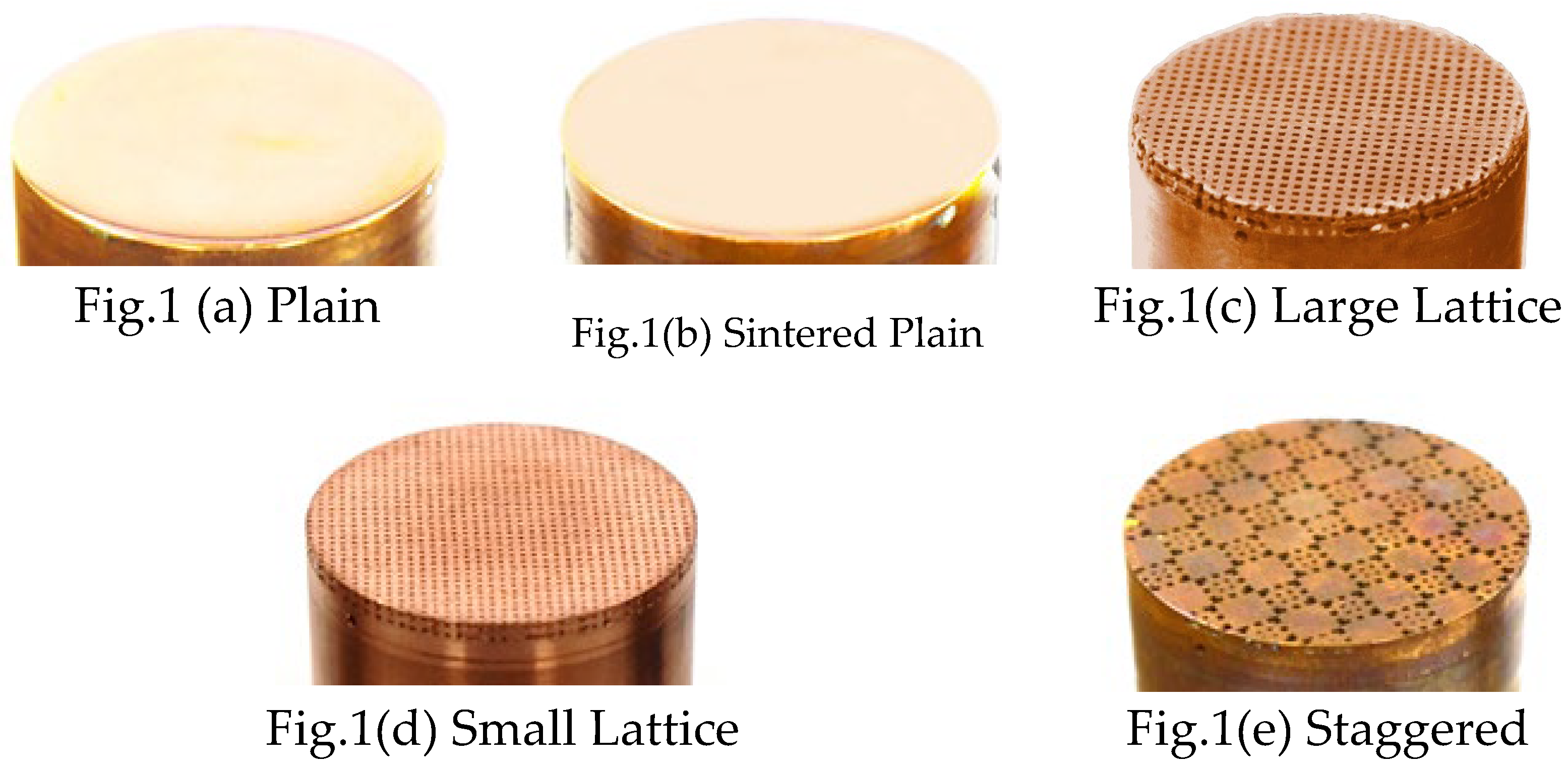
Figure 2.
Location of surface roughness measurement.
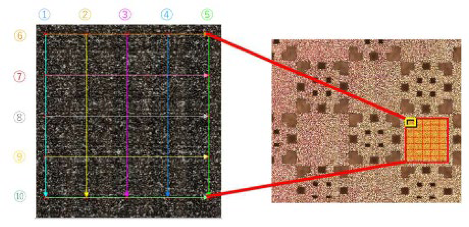
Figure 3.
SEM images of the BJ3DP surface.
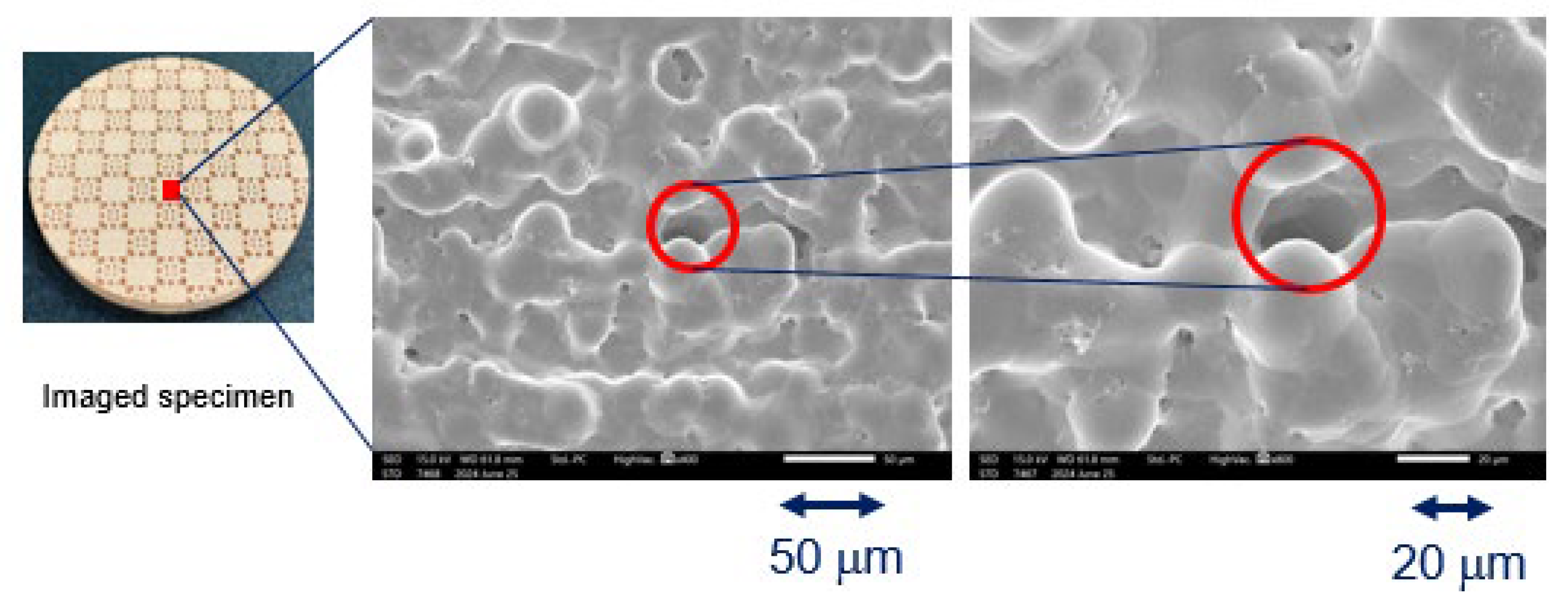
Figure 4.
(a) Photo image of the experimental setup; (b) schematic diagram of the experimental setup.
Figure 4.
(a) Photo image of the experimental setup; (b) schematic diagram of the experimental setup.
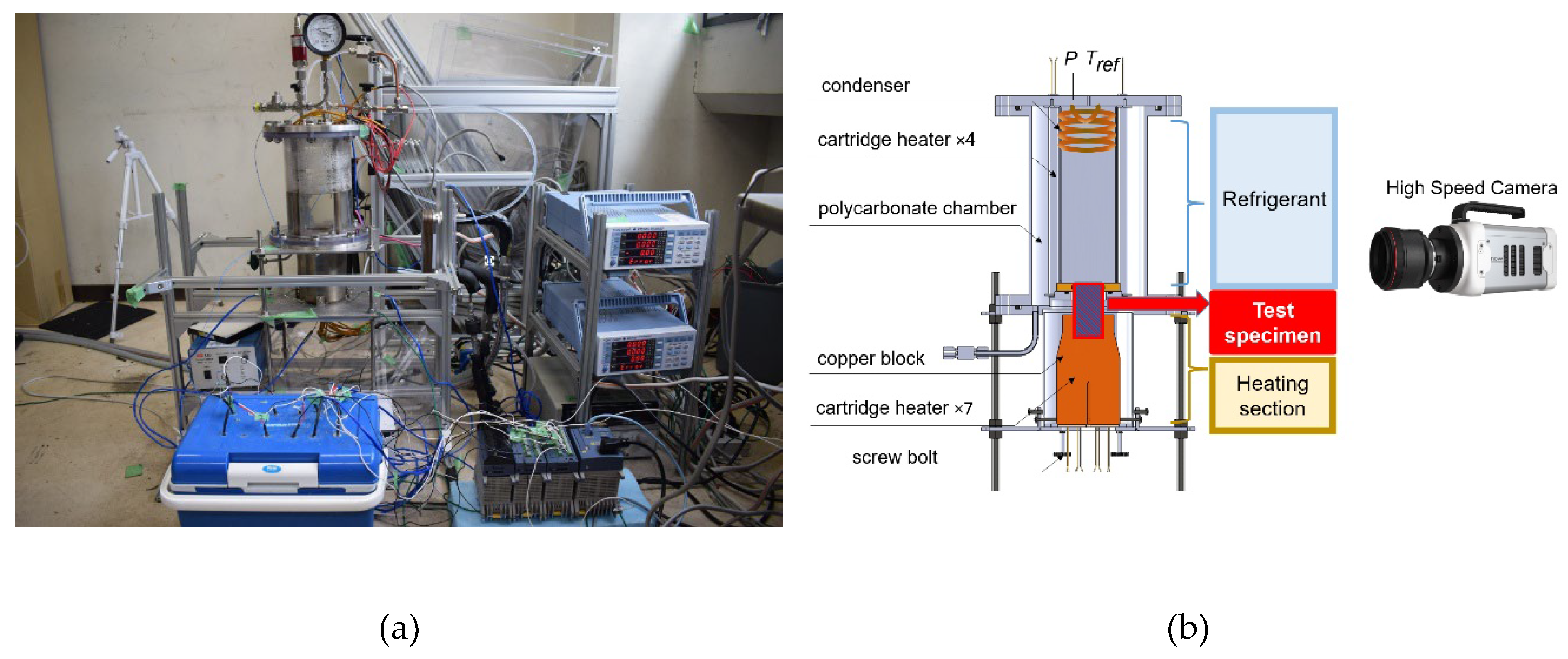
Figure 5.
Test section view: (a) locations where the thermocouples were inserted (b) representative plot of the temperature profile along the block height.
Figure 5.
Test section view: (a) locations where the thermocouples were inserted (b) representative plot of the temperature profile along the block height.
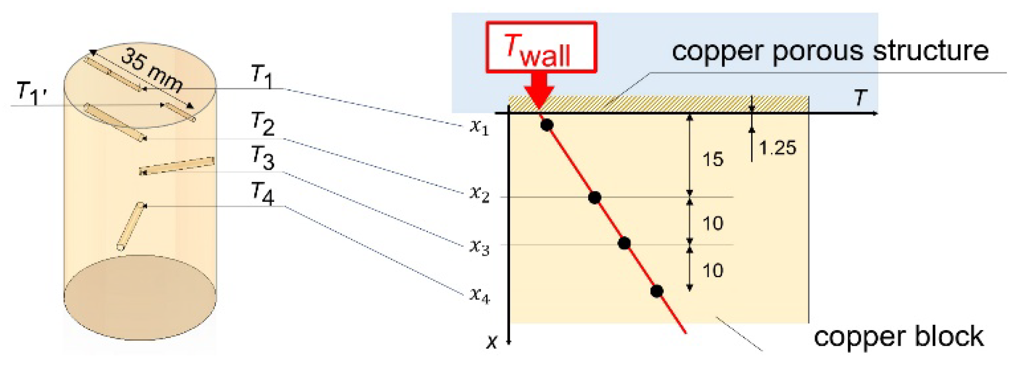
Figure 6.
Pool boiling validation against Stephan & Abdelsalam correlation.
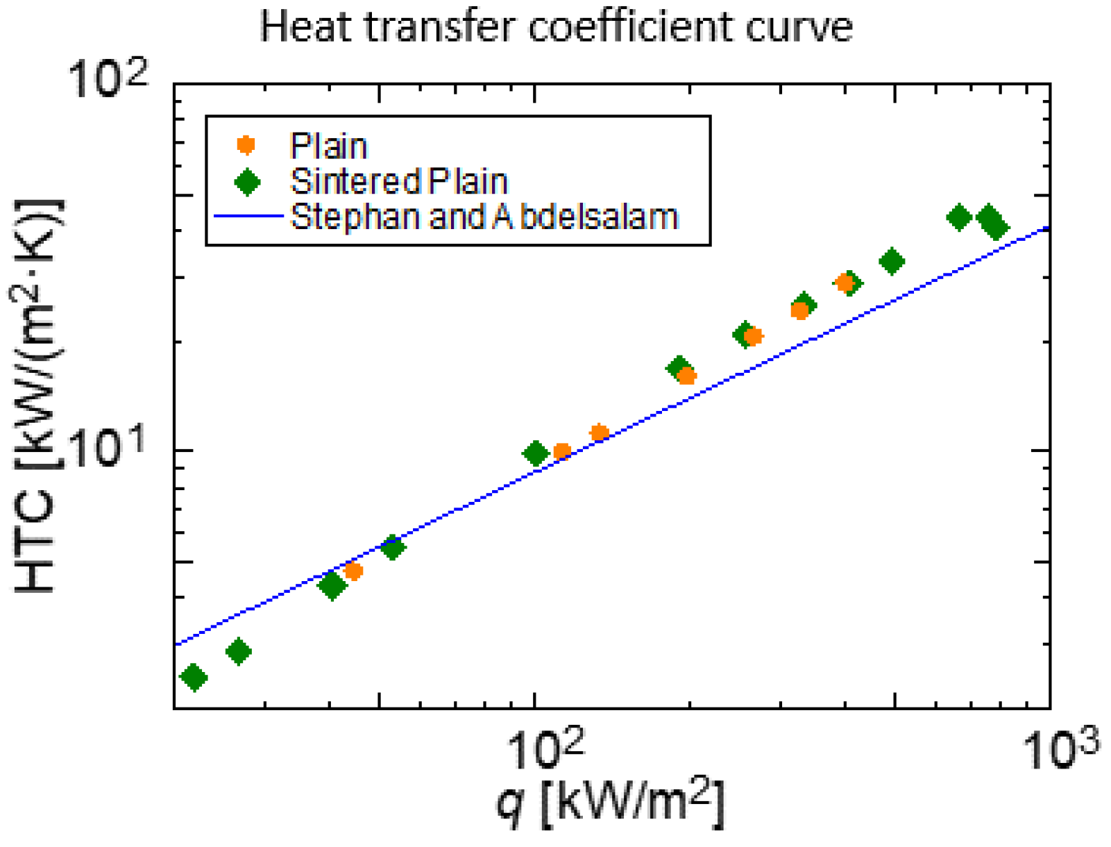
Figure 7.
Boiling curve.
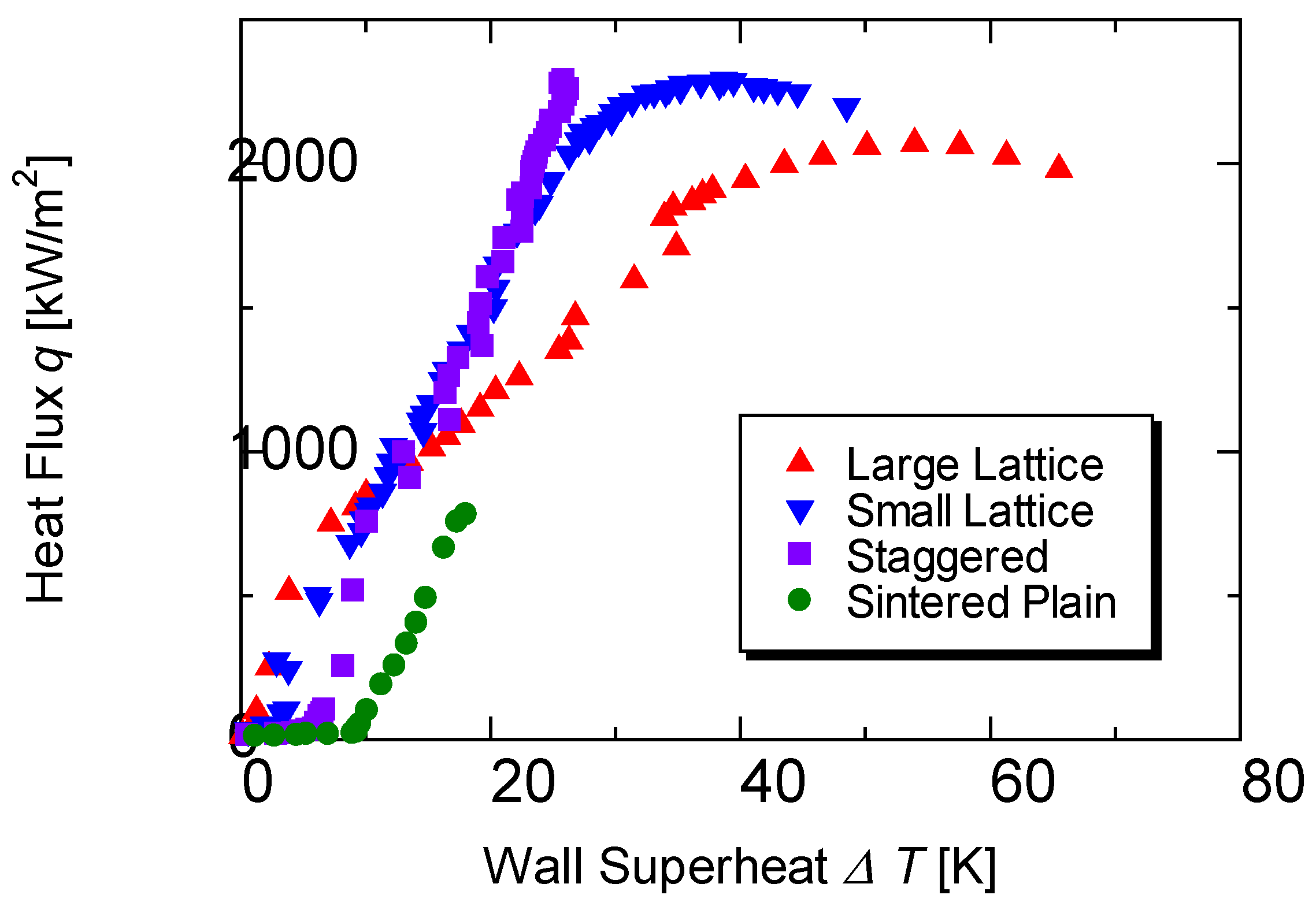
Figure 8.
HTC curve.
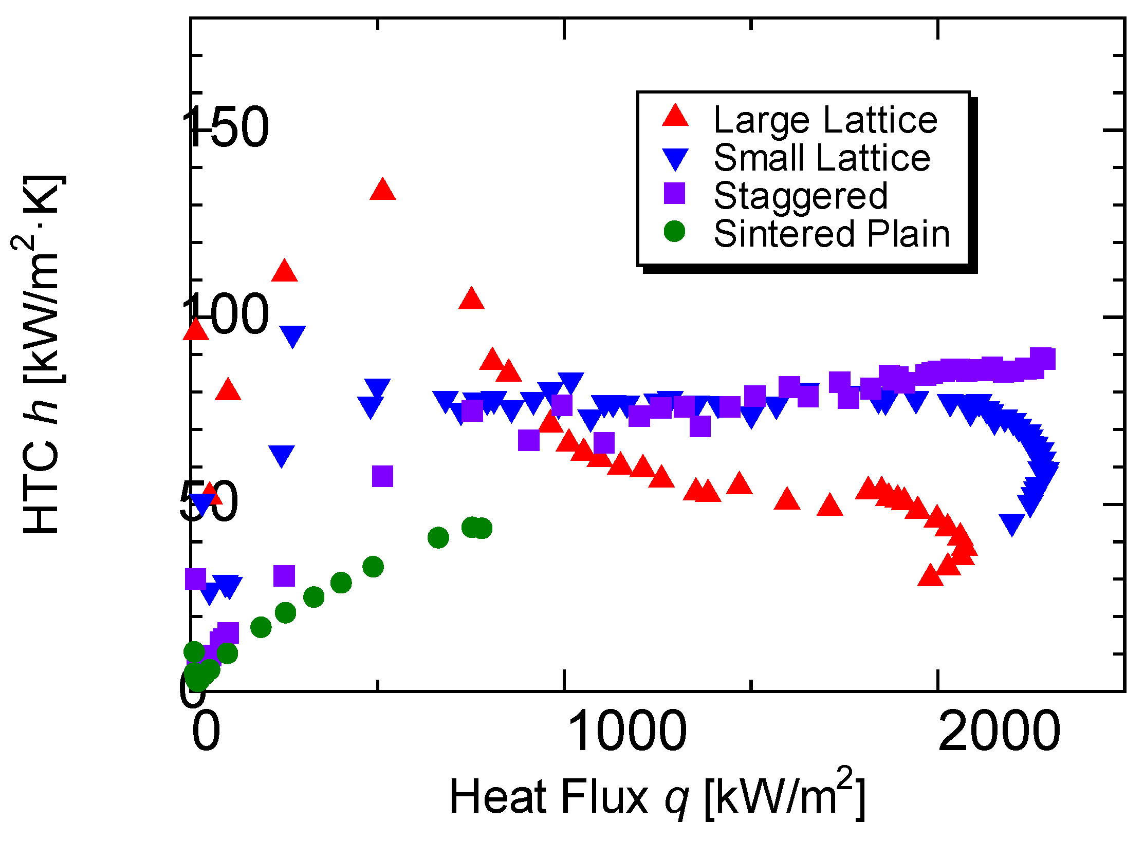
Figure 9.
Bubble growth characteristics (q = 50 kW/m2).
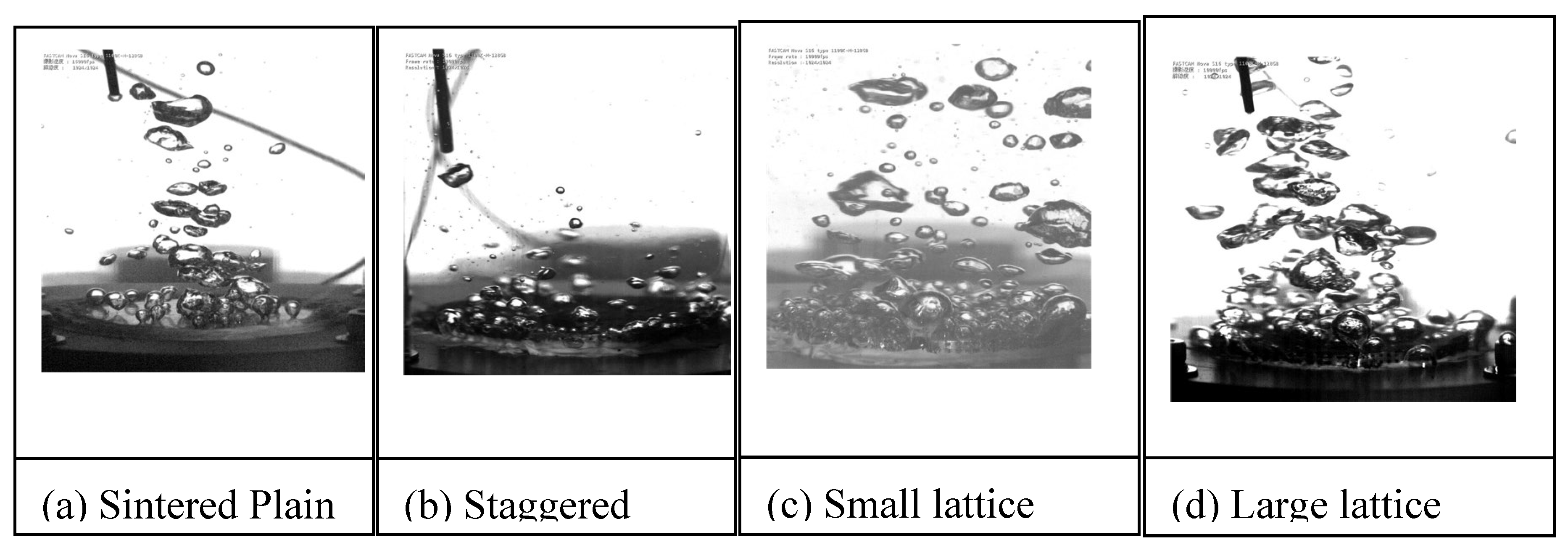
Figure 10.
Bubble growth characteristics (q = 100 kW/m2).
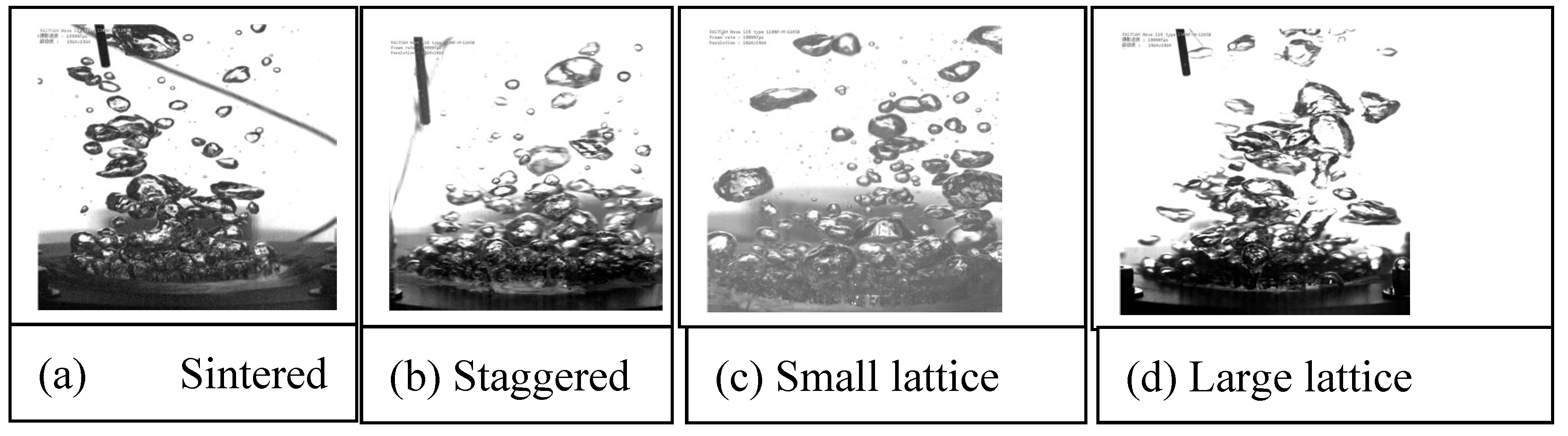
Figure 11.
Bubble growth characteristics (q = 250 kW/m2).
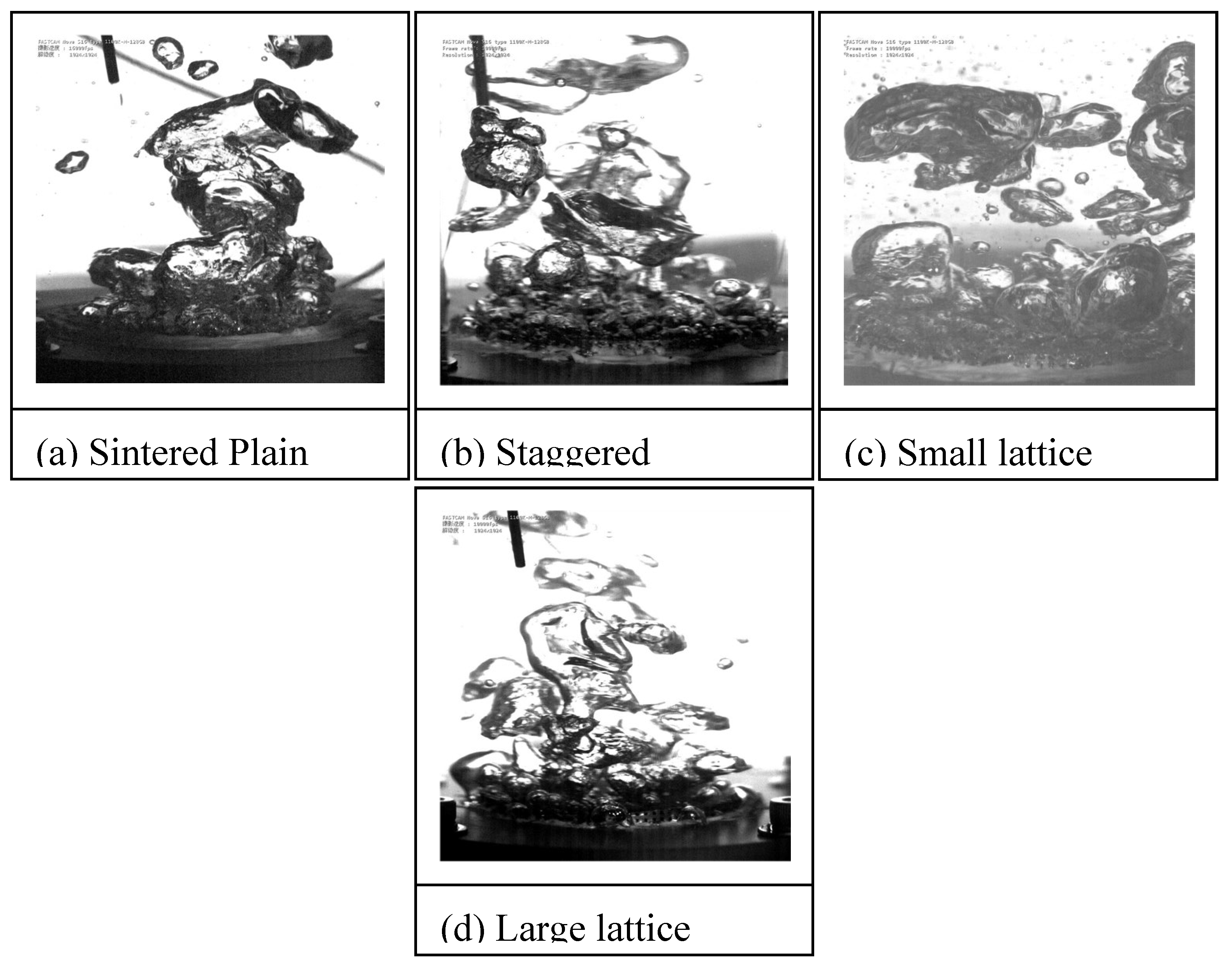
Figure 12.
Bubble growth characteristics (q = 500 kW/m2).
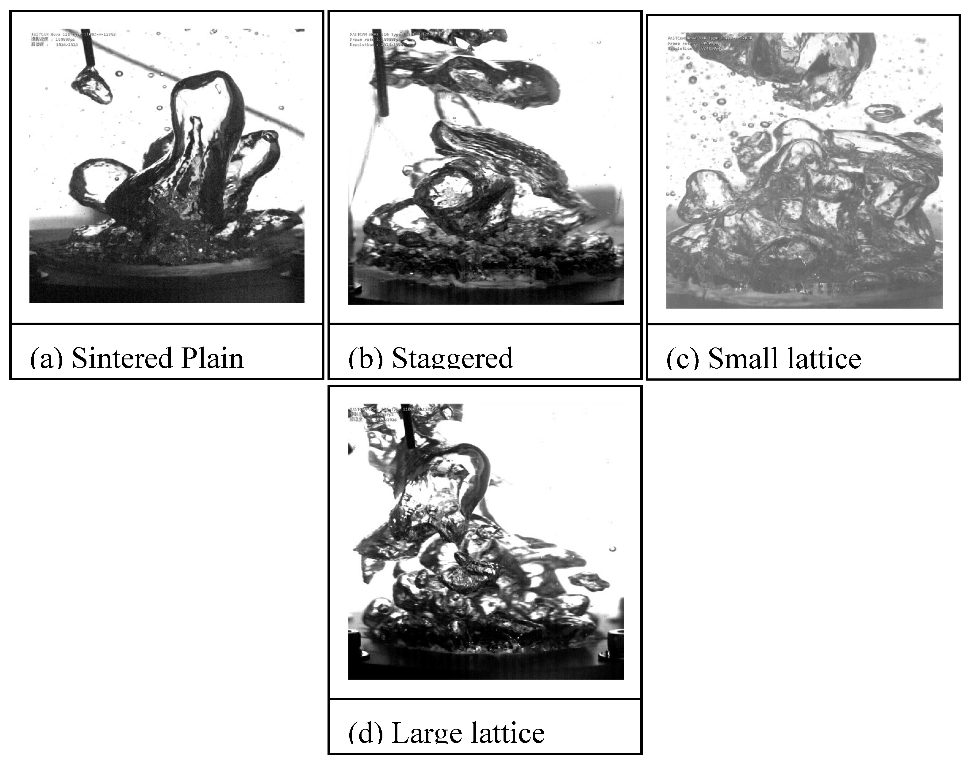
Figure 13.
Bubble growth characteristics (q = 1000 kW/m2).
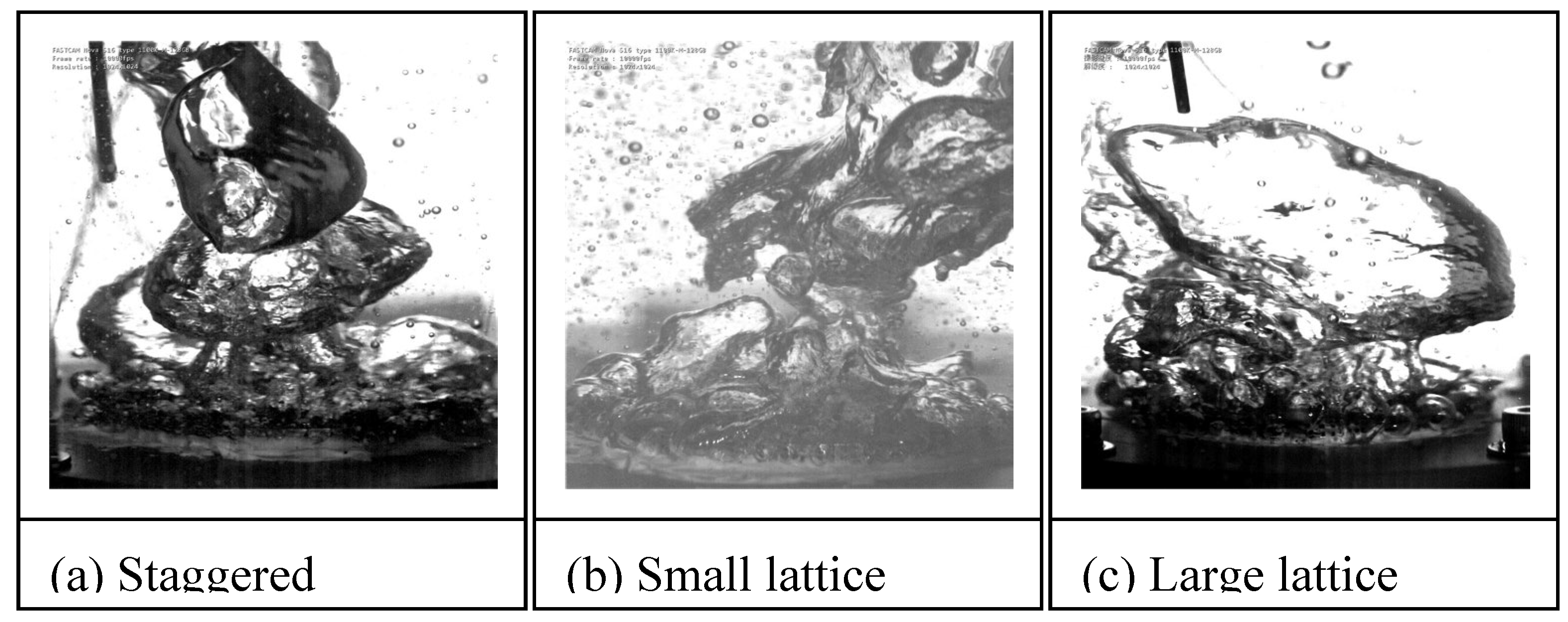
Figure 14.
Bubble growth characteristics (q = 2000 kW/m2).
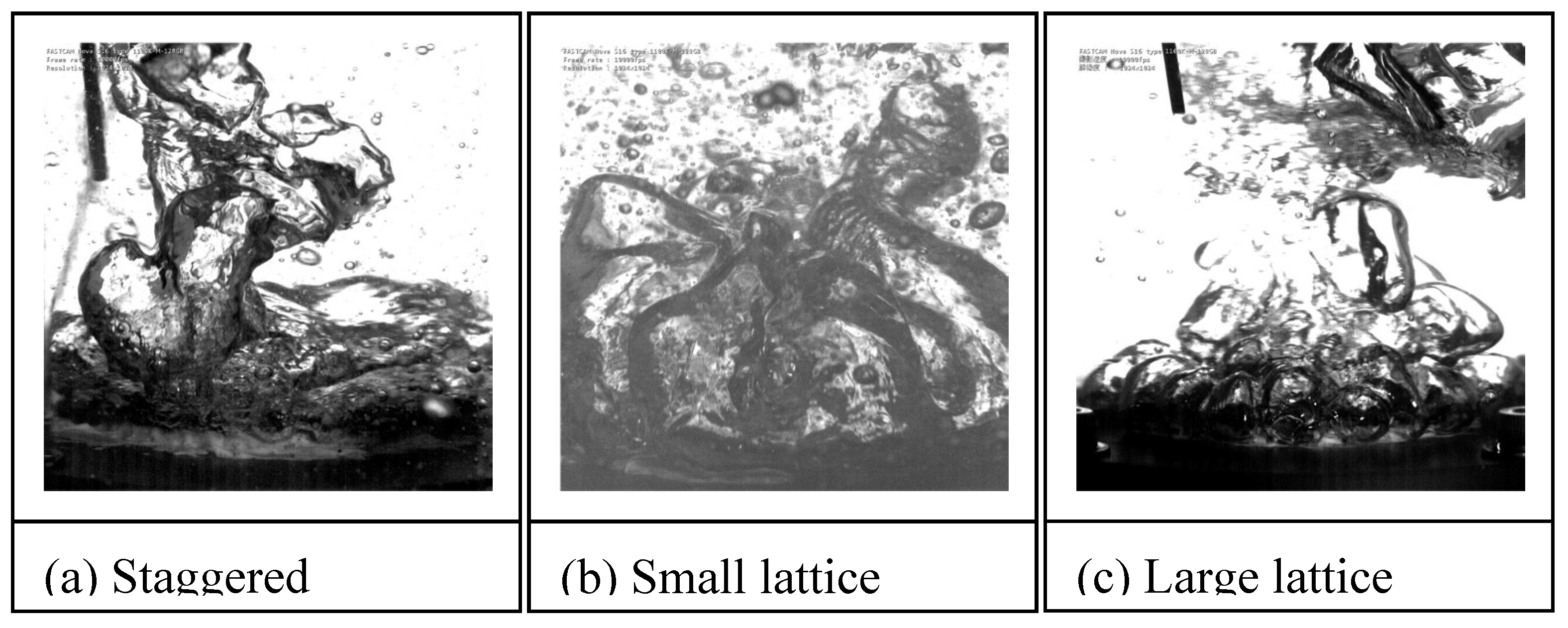
Figure 15.
Bubble growth characteristics (CHF for Staggered, q =2060 kW/m2 for Large lattice, q =2281 kW/m2 for Small lattice).
Figure 15.
Bubble growth characteristics (CHF for Staggered, q =2060 kW/m2 for Large lattice, q =2281 kW/m2 for Small lattice).
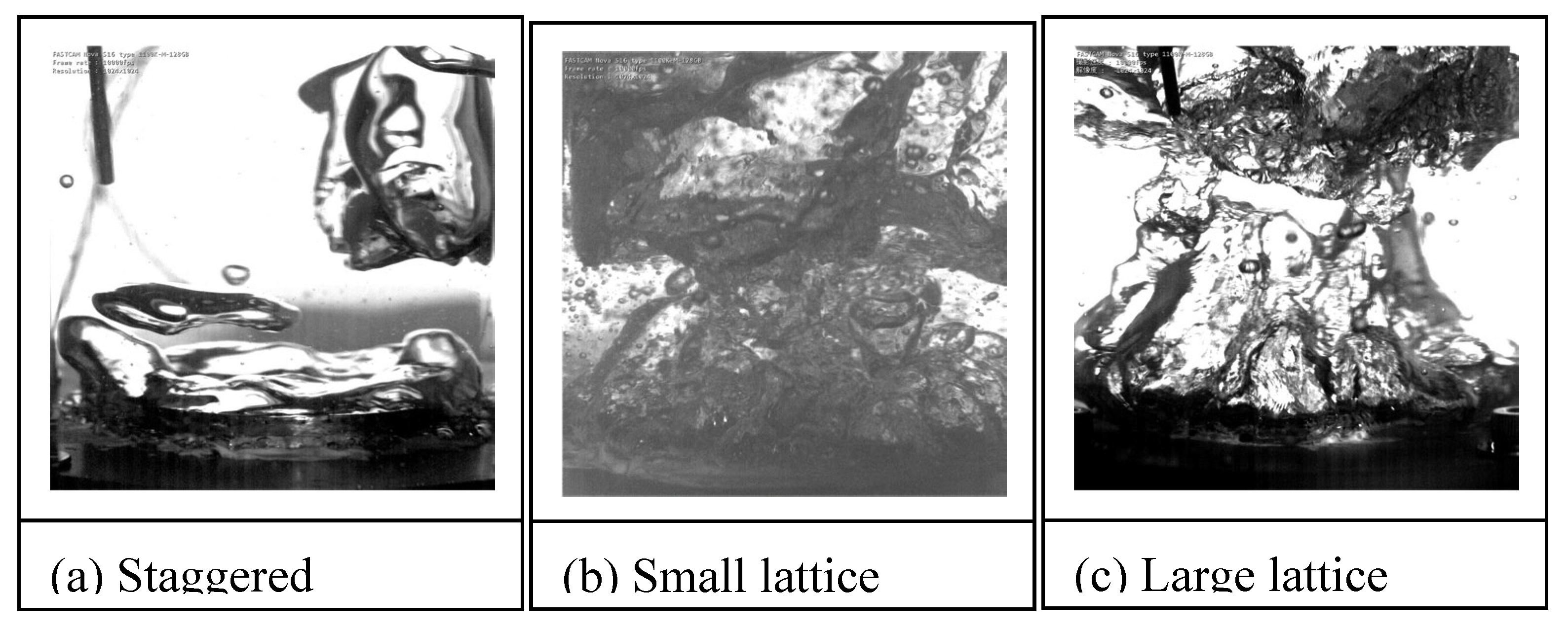

Table 1.
Surface Roughness measurements.
| Line | Ra(μm) | RZ(μm) |
|---|---|---|
| 1 | 9.77 | 61.5 |
| 2 | 9.95 | 74.5 |
| 3 | 9.26 | 75.3 |
| 4 | 9.07 | 79.8 |
| 5 | 9.71 | 74.5 |
| 6 | 9.46 | 67.7 |
| 7 | 7.77 | 62.5 |
| 8 | 9.46 | 74.1 |
| 9 | 10.13 | 62.2 |
| 10 | 8.89 | 77.8 |
Disclaimer/Publisher’s Note: The statements, opinions and data contained in all publications are solely those of the individual author(s) and contributor(s) and not of MDPI and/or the editor(s). MDPI and/or the editor(s) disclaim responsibility for any injury to people or property resulting from any ideas, methods, instructions or products referred to in the content. |
© 2025 by the authors. Licensee MDPI, Basel, Switzerland. This article is an open access article distributed under the terms and conditions of the Creative Commons Attribution (CC BY) license (http://creativecommons.org/licenses/by/4.0/).
Copyright: This open access article is published under a Creative Commons CC BY 4.0 license, which permit the free download, distribution, and reuse, provided that the author and preprint are cited in any reuse.


