Submitted:
24 December 2025
Posted:
15 January 2026
You are already at the latest version
Abstract
In the grinding of silicon carbide, surface and subsurface damage have a significant im-pact on the product's surface quality. A method to obtain controllable crack dimension through laser irradiation on SiC surface and its effect on the grinding process was ana-lyzed. A series of experiments were carried out based on the orthogonal experimental de-sign, with systematic adjustments made to laser parameters including pulse energy (cur-rent), laser spot spacing, scanning times as well as grinding process parameters. During the experiments, the grinding force was monitored by a dynamometer, and the specific grinding energy was calculated accordingly. Pulsed engraving laser modification could effectively reduce the hardness of the ceramic surface layer by about 20%. The median and radial crack sizes in the subsurface layer induced by laser were in the range of 20.4 μm to 54.3 μm, which could effectively inhibit the further propagation of median and radial cracks during grinding, and simultaneously reduce the tangential grinding force Ft by about 30%. These conclusions were obtained by corresponding experiments, which link the surface roughness with laser power to grinding parameters. The laser induced con-trollable crack characteristics on the grinding process are conducive to realizing the con-trol of surface and subsurface grinding damage of brittle materials.
Keywords:
SiC
; laser modification
; grinding
; surface hardness
; crack
1. Introduction
SiC is a hard, brittle, and difficult-to-machine material. During the grinding process, subsurface damage, high-pressure phase transformation, cracks, brittle fracture, residual stress and other issues often occur, which affect the integrity of the machined surface. In particular, chipping at the material edges, surface cracks, and pits are detrimental to the service performance of machined parts, especially their fatigue life. Reducing surface defects during machining or grinding has always been the core of machining research [1,2,3,4]. The brittle material damage model proposed by Lawn and Wilshaw [5] is the main basis for analyzing subsurface cracks.
Many scholars have been committed to applying grinding technology to the surface processing of SiC. Kizaki et al. [6] proposed ultraviolet laser-assisted precision cutting of zirconia ceramics, and the results showed that the introduction of laser significantly reduced the number of macro-cracks and decreased the specific cutting energy by 35%. Azarhoushang et al. [7] studied the successful application of ultra-short pulse laser in the silicon nitride grinding process, realizing efficient material removal, controllable thermal damage and improvement of material removal rate through laser radiation.
The combination of laser and traditional machining methods has given rise to a variety of hybrid machining approaches, such as Laser and Ultrasonic Vibration Assisted Machining (LVC) [28], Laser assisted Machining (LAM) [9,26], laser assisted drilling [20] , laser assisted grinding [26,27,28,29], and laser cutting [17] . Among these, a typical research method is to conduct scratch tests using single abrasive grains.
The primary objectives of machining are to achieve high surface quality, low power consumption and reduced tool wear [8,9,11,13,14]. Research on surface quality focuses on inhibiting subsurface brittle fracture propagation and expanding the plastic deformation zone [13,15]. Meanwhile, studies on chip morphology and failure modes are important parts of machining mechanism research [13,28]. Based on fracture mechanics theories [9,10,13], the brittle-ductile transition and critical transition scale is the key to surface quality control [8,9,19,24]. Consequently, relevant research on crack initiation, propagation, prefabricated cracks [16] and crack control [24] has been carried out smoothly. Further analysis at the crystal level involves aspects such as slip, stacking, stacking faults and amorphization [24,34,35].
Crack initiation and propagation are usually induced by force/stress [8,9,11,28], which is not easy to be observed during the machining process. By means of SEM, EDS and white light interferometry, geometric characteristics can be detected, including surface topography [9,10,20,29], crack distribution and surface defects [6,7].
Fracture theory is usually based on indentation fracture experiments. Methods adopted in experiment include indentation tests [4], control experiments (conventional cutting) [8,9], Taguchi methods (for analyzing cutting forces and surface quality under different machining conditions) [23], Box-Behnken experimental design [13], response surface methodology (RSM) [13] and design of experiments (DoE) [16]. In the experiments, characterizations are usually performed on morphology [9], surface defects and roughness [8,9,19,28]. At the microscale, detections are carried out on cracks/microcracks [8,9,10,11] and surface/subsurface damage [7,15]. In addition, measurements or calculations can also be conducted for force/stress [28], specific grinding energy [6,11], hardness [16], etc.
Experiments are conducted under limited conditions, and the introduction of theoretical analysis helps to generalize and extend the experimental results. In this regard, commonly used theoretical analyses include thermo-mechanical coupling simulation [12], temperature field simulation [27], finite element model (FEM) [28], molecular dynamics simulation [35], surface roughness model [13,23], subsurface damage scale model [15], grinding force prediction model [13], tool wear model, etc.
Rao et al. [31] analyzed material removal mechanism of grinding surfaces during the grinding process of RB-SiC. They found that the grinding surfaces are mainly characterized by brittle pits, abrasive scratches, and plastic grooves. Chen et al. [35] investigated the variation laws of stress, temperature, dislocation, surface topography, and crystal structure of single-crystal and polycrystalline silicon carbide with changes in grinding speed and grain size through molecular dynamics simulations.
Qu et al. [38] studied that the material removal of single-crystal 4H-SiC during the grinding process is mainly achieved through plastic deformation, accompanied by brittle fracture.
At present, extensive research on the grinding process of silicon carbide is carried out, covering aspects from the grinding removal mechanism at the micro level to the proposal of various new process methods such as composite grinding. In order to study how to reduce the damage during the silicon carbide processing and improve the processing efficiency, this study adopts engraving laser to modify the surface of silicon carbide, explores the action mechanism of laser irradiation on the surface properties of silicon carbide, controls the surface crack size of laser-modified silicon carbide, restricts the extension and propagation of radial cracks and median cracks during grinding processing, and analyzes the effect of surface cracks of laser-modified silicon carbide on the grinding process.
2. Experimental
2.1. Sample Surface Preparation
A green laser with a wavelength of 532 nm was used as the internal carving light source (PHANTOM Ⅰ laser internal carving machine produced by Han's Laser Group, China). The silicon carbide ceramic sheets produced by the pressureless sintering process (Beilong Electronics Co., Ltd., Guangdong, China) were irradiated. The laser was focused on the processed area below the surface layer of the sample, and the material was ablated at the focal point to modify the processed area of the material surface layer.

Table 1.
Performance parameters of silicon carbide ceramic materials.
| parameters | values |
|---|---|
| Density(kg·cm-3) | 3.12 |
| Elastic Modulus (GPa) | 415 |
| Vickers Hardness (HV) | 3000 |
| Fracture Toughness (MPa·m1/2) | 4.5 |
| Thermal Conductivity (W/m·k) | 148 |
| Melting Point (℃) | 2700 |
| Poisson's Ratio | 0.24 |
| Thermal Expansion Coefficient() | 4.2 |
A pulsed engraving laser processing system was used to irradiate the surface of silicon carbide ceramics, where the specific parameters of the laser engraving machine are listed in Table 2. The green laser output by the laser system was expanded by a beam expander, then reflected to a focusing lens via an XY galvanometer. Controlled by a computer, the XY galvanometer swings to enable precise control of the laser focus in the XY two-dimensional directions, thereby regulating the laser beam's processing on the two-dimensional plane. The laser output power was adjusted by changing the output current; the laser defocus value was changed by adjusting the height of the processing platform in the Z-axis direction; the hardness and microcrack size of the laser induced layer were altered by adjusting the spot spacing and scanning times of the laser output.
The hardness of the laser-modified layer on silicon carbide ceramic was measured, and the micro-topography was observed. A digital micro Vickers hardness tester (HVS-1000M, Lead Instrument Co., Ltd., Ningbo, China) was used to measure the microhardness of the laser-irradiated region. A super-depth microscope (VHX-1000, Keyence Corporation, Japan) was employed for crack topography observation. The microscope is equipped with low- and high-magnification lenses, with the low-magnification lens capable of magnifying up to 200× and the high-magnification lens up to 5000×. Additionally, the microscope can perform depth-of-field synthesis on the measured area to automatically generate a 3D surface profile map within the range.
The phase composition of the laser-modified layer on silicon carbide ceramic was analyzed using an X-ray diffractometer (smartlabX, Lihua Saisi Technology Co., Ltd., Beijing), with an angular resolution of 0.001°, to precisely identify the phase composition based on diffraction principles. In the experiment, two silicon carbide ceramic wafers were bonded together with wax to facilitate the observation and analysis of the subsurface conditions and the depth of the laser-affected thermal modification layer, as shown in Figure 1.
By adjusting the current, the output power of the laser engraving machine can be changed, so the current parameter is used to characterize the laser power. The laser current, number of scans, defocus amount, and spot spacing were selected as the laser process parameters to optimize the control of micro-crack scale in the machined area and its characterized surface hardness.
The thermal-induced cracks were generated by the internal engraving laser on the material surface, which has a significant impact on the material hardness. Material hardness is an extremely important material property index affecting the grinding process, as it will significantly influence the wear degree of the grinding wheel, the grinding force, and grinding efficiency during the process. These results will be presented in another article, and the role of cracks in grinding will be briefly discussed later. Therefore, analyzing the influence of different laser process parameters on the crack scale in the surface layer of silicon carbide ceramics and applying these findings to the relevant grinding process are of paramount importance for improving the grinding efficiency of silicon carbide ceramics, reducing the grinding force, and minimizing surface defects during the grinding process.
Figure 2.
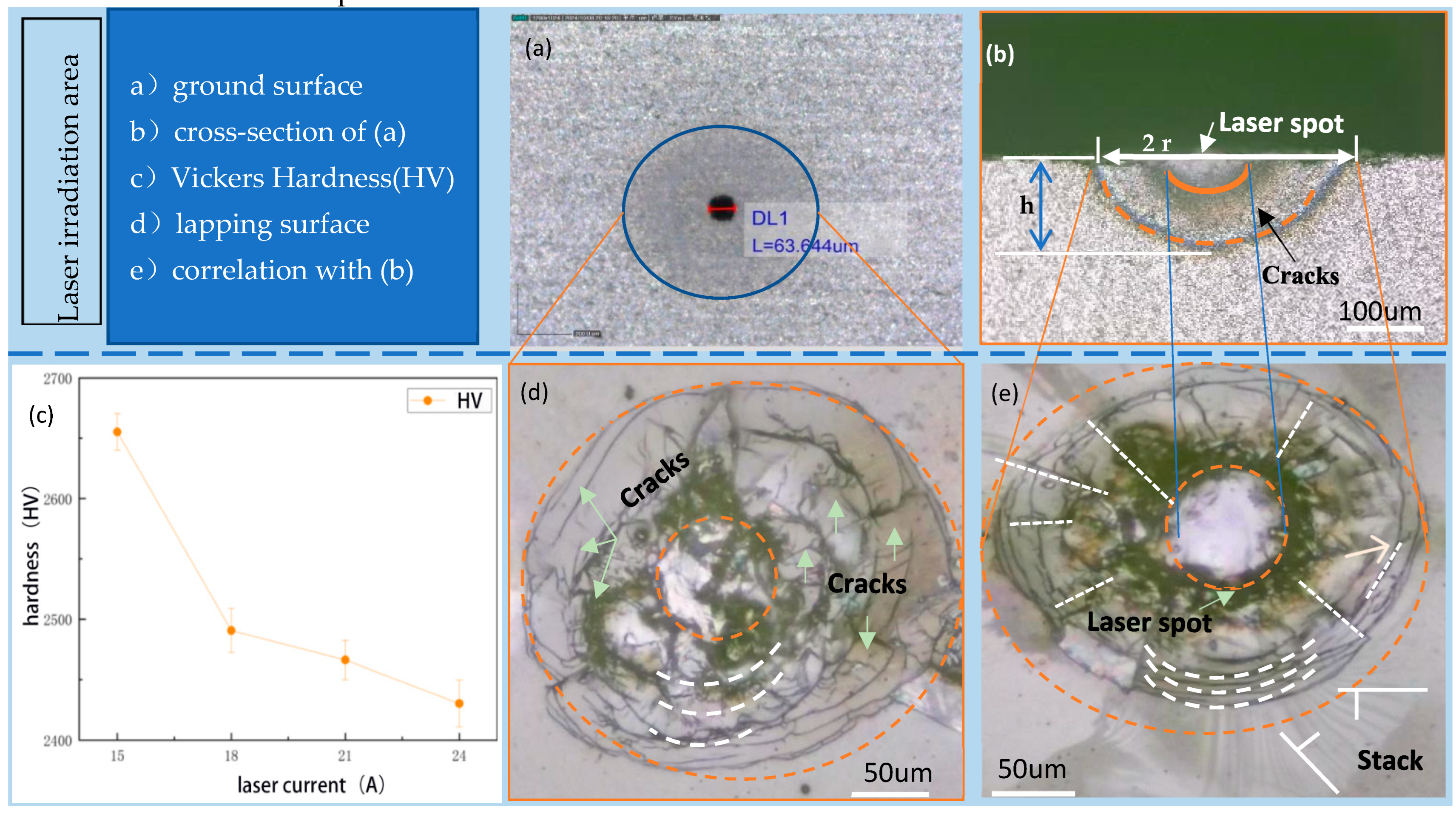
Crack Characteristics of SiC Ceramic Surface Layer. (a) Ground surface with laser spot measured. (b) cross-section of (a). (c) hardness of sample measured by Vickers hardness tester. (d) correlation surface of sample after lapping. (d) another correlation surface of sample after lapping.
Figure 2.
Crack Characteristics of SiC Ceramic Surface Layer. (a) Ground surface with laser spot measured. (b) cross-section of (a). (c) hardness of sample measured by Vickers hardness tester. (d) correlation surface of sample after lapping. (d) another correlation surface of sample after lapping.
2.2. Grinding Experiment Scheme
To verify that the laser modification method for ceramic surface layers can effectively reduce grinding force and prevent crack propagation, a high-speed precision engraving machine (Mikael 300Q, Mikael CNC Technology Co., Ltd., Guangdong, China) was used with a 400-mesh diamond electroplated grinding head. The grinding test bench and abrasive tool are shown in Figure 3.
A dynamometer (KWR75, Kunwei, Technology Co., Ltd., Guangzhou) was used to measure the grinding force during the grinding process, as shown in Figure 3. Diamond wheel grinding remains the primary grinding method for silicon carbide ceramics. Electroplated grinding wheels offer the advantage of high bonding strength, so an electroplated diamond wheel with an abrasive grain size of 400# and a wheel diameter of 10 mm was selected for the experiment, as detailed in Table 3.
Grinding force is generally decomposed into three directions: normal grinding force Fn,tangential grinding force Ft, and axial grinding force Fa. However, Fa is usually small and its impact on the machining process can be neglected. In the experiment, the grinding force was measured three times for each set of process parameters. Abrupt signals in the grinding force data were eliminated, and the average value of the grinding force during the stable grinding stage was taken as the final result to avoid the influence of contingency and random errors in the experiment on the test outcomes.
3. Results
3.1. Crack Dimensions
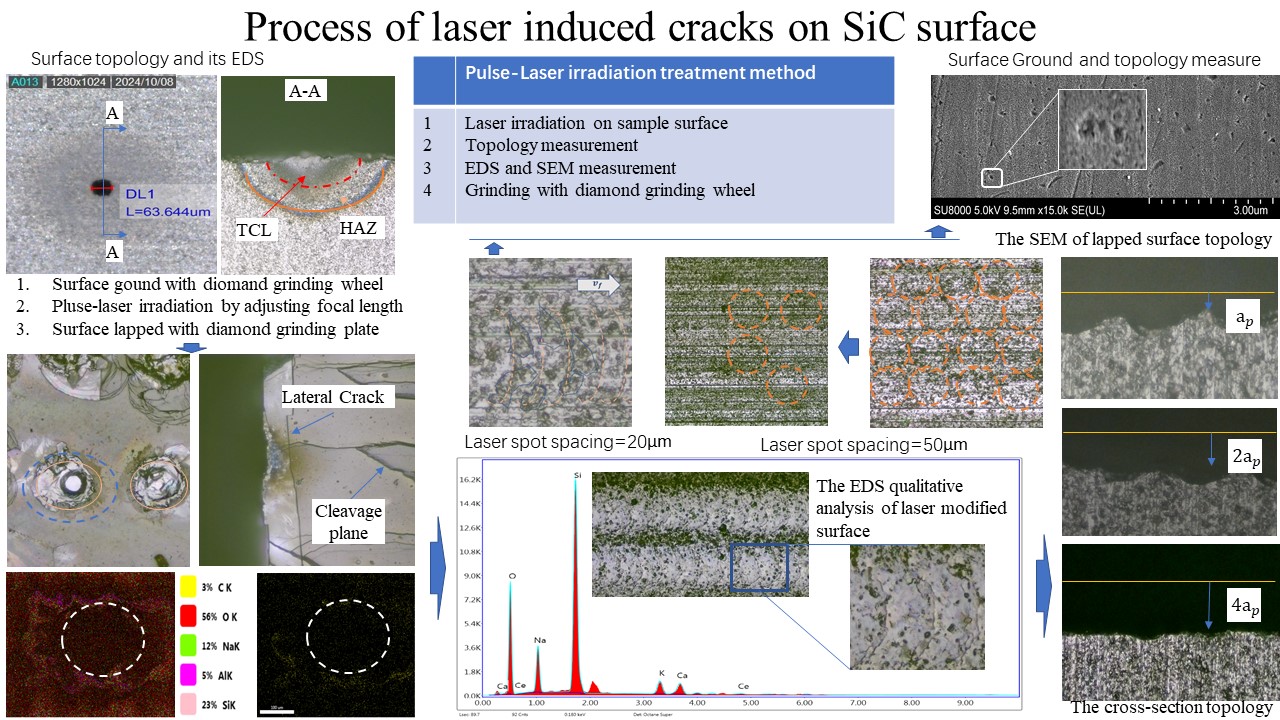
The surface topography of SiC ceramics treated by internal carving laser was shown in Figure 4. The laser-modified layer consists of pulsed laser spots, thermal cracks layer (TCL) and heat affected zone (HAZ). The diameter d and depth h of thermal cracks layer is a core indicator to evaluate the effect of laser surface treatment, as it reflects the direct influence of laser on the material's surface properties (e.g., surface hardness, fracture toughness).
Additionally, the subsequent grinding process needs to completely remove the TCL and HAZ. Therefore, accurate measurement of the thickness of the thermal cracks layer and the HAZ after laser modification is of great significance for the subsequent grinding experiment.
The cross-sectional topography of silicon carbide was measured, which was influenced with laser parameters including laser current, scanning times, defocus value, and spot spacing. It can be observed that laser parameters have a significant impact on the depths of the thermal cracks layer and the HAZ. When the laser current is 15 A, the depths of the thermal cracks layer are close to that of HAZ. As the laser current increases to 18 A, the boundary between the thermal cracks layer and the HAZ begins to become clear. When the laser current further increases to 21 A and 24 A, due to the increased laser energy density, the surface oxide layer gradually thickens, and a white oxide layer can be clearly observed in the laser-modified zone.
As the number of laser scans times increases from 1 to 4, the depths of the thermal cracks layer and the HAZ gradually increase, while the surface oxide layer also thickens progressively. When the defocus amount increases from 0 mm to 1 mm, the dimension of the thermal cracks zone increases significantly. The reason may be that the focal point of positive defocus is located above the sample surface, where the spot diameter formed by the laser beam on the sample surface is larger than that at the focal point. When the defocus amount is further increased to 2 mm and 3 mm, as the distance between the focal point and the sample surface gradually increases, a large amount of energy dissipates in the air, resulting in a decrease in the effective energy transmitted to the material surface, and the width of the modified zone gradually decreases.
Figure 5.
Dimension measure of the TCL and the HAZ. (a)~(d) the correlation of the dimension of TCL and HAZ with laser power (indexed by laser current). (e)~(h) the correlation of the dimension of TCL and HAZ with scanning times. (i)~(l) the correlation of the dimension of TCL and HAZ with defocus amount. (m)~(p) the correlation of the dimension of TCL and HAZ with spot spacing.
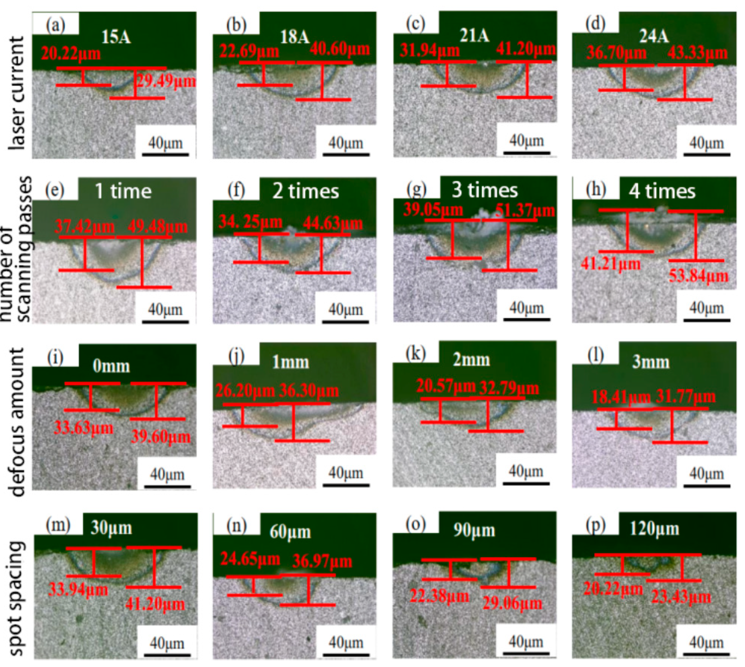
When the spot spacing increases to 90 μm and 120 μm, the depths of the thermal cracks layer are close to that of the HAZ. This may be attributed to the fact that with the increase in spot spacing, the energy absorbed by the material per unit area decreases, leading to reduced thermal accumulation, which in turn results in a significant reduction the HAZ comparable to that of the thermal cracks layer.
When the times of laser scans reaches 4, the silica oxide layer can reach a maximum depth of 20.13 μm, the TCL up to 41.21 μm, and the laser HAZ up to 53.84 μm. Spot spacing affects the energy accumulation effect and the continuity of the scanned area. At small spot spacing, adjacent spots overlap, and the same region is heated by other two pulses spots. Energy accumulation increases the peak temperature, promoting deep thermal diffusion.
3.2. Surface Hardness
Vickers hardness tester with a square pyramid diamond indenter was used to measure the hardness of the laser-modified region. After the hardness tester automatically loaded, held the load, and unloaded, the lengths of the two diagonals of the indentation in the target area were manually calibrated. Subsequently, the hardness tester automatically calculated the corresponding hardness value according to the Vickers hardness empirical formula.
As the laser current increases from 15 A to 24 A, the surface hardness shows a gradual decreasing trend, indicating that the increase in laser current has a significant weakening effect on the material's surface hardness, as shown in Figure 6a. As the current increases, the laser output power gradually increases, leading to a higher laser energy per unit area. After being transmitted through the optical path and focused onto the silicon carbide surface by the focusing lens, part of the laser energy is absorbed by the material, causing the surface temperature to rise.
The surface hardness of silicon carbide gradually decreases with the gradual increase in the number of laser scans. When the number of scans increases from 1 to 2, the surface hardness of silicon carbide decreases most significantly, while the decreasing trend of surface hardness slows down when the index of scans increases to 3 and 4, shown in Figure 6b.
3.3. Surface Topography and Composition
Since the powdery ablated products generated on the surface during laser irradiation are insufficient for individual detection, XRD analysis was performed on the entire laser-treated surface of the silicon carbide ceramics after laser irradiation. The overall topography of the sample is shown in Figure 7a, the characteristic peaks of the SiC matrix are presented in Figure 7c, and the characteristic peaks of the modified products are illustrated in Figure 7b.
By comparing the XRD spectra of silicon carbide ceramics before and after laser modification, it is found that prior to laser modification, the characteristic peaks appear at 2θ = 34.061°, 35.597°, 38.268°, 41.383°, 43.253°, 54.581°, 60.024°, 66.654°, 71.651°, 72.327°, 73.513°, and 76.304°. Comparison with the standard PDF card confirms that all these characteristic peaks correspond to the SiC phase, indicating that the main constituent phase of the silicon carbide ceramics before laser modification is the SiC phase. After laser modification, in addition to the aforementioned characteristic peaks, a weak-intensity characteristic peak emerges at 2θ = 23.749°, which is identified as the SiO₂ phase by reference to the standard PDF card. Thus, the main phase generated on the silicon carbide surface after laser modification is the SiO₂ phase.
Surface roughness measurements of the silicon carbide were conducted, as shown in Figure 7d. The results indicate that when the laser current is 15 A (with low laser power), the surface roughness is 1.452 μm. As the laser current increases to 18 A, the surface roughness rapidly rises to 1.73 μm, and further increases in laser current result in little change in surface roughness. This is because at low laser current, the laser power is insufficient to induce continuous melting of the silicon carbide surface.
3.4. Grinding Process
The presence of surface and subsurface cracks significantly reduces the grinding force. As the laser current gradually increases, both the normal grinding force Fn and tangential grinding force Ft decrease progressively. Compared with the control group without laser modification, the grinding forces are reduced to varying degrees, as shown in Figure 8. The ground surface undergoes further lapping treatment, and its topography is presented in Figure 8a.
When the laser current is 15 A, the normal grinding force decreases by 2.9% compared with conventional grinding, and the tangential grinding force decreases by 3.2%. This is because the laser energy is relatively low at this point, and the insufficient energy input only induces a weak phase transformation on the silicon carbide surface. The overall hardness and brittleness show no significant reduction, with the material still dominated by its original high-hardness and high-brittleness structure. During grinding, the resistance to abrasive grain penetration and the energy consumption for crack propagation are not significantly reduced, resulting in a small decrease in grinding force.
When the laser current reaches 24 A, both the Fn and Ft drop to the minimum. Compared with the experimental group without laser modification, the normal grinding force is reduced by 17.6% and the tangential grinding force by 22.2%. It can also be observed that the trend of the actual values is consistent with the theoretical values, but the theoretical values are larger than the actual ones. The maximum deviation is 32.1%, the minimum deviation is 5.8%, and the average deviation is 18.6%.
In summary, laser-modified silicon carbide ceramic grinding results in a significant reduction in both normal and tangential grinding forces. With the increase in laser current, the laser power increases, the surface hardness of silicon carbide ceramics continuously decreases, and the corresponding reduction ratio of grinding force gradually increases. The maximum reduction in normal grinding force can reach 17.6%, and that in tangential grinding force can reach 22.2%.
The specific grinding energy under I, Vsr was plotted as a dot-line graph. The curves showing the variation of specific grinding energy with laser power (indexed by current) and grinding wheel speed are presented in Figure 9.
4. Discussion
4.1. Thermal Distribution Simulation
The internal temperature of the laser-irradiated region in ceramic materials is related to the laser energy density , laser moving speed vp, laser spot diameter 2rb, laser irradiation time tp, and the material properties of the ceramic itself. Therefore, the material temperature can be expressed by Equation (1):
where: K denotes the thermal conductivity of the material, and C denotes the specific heat capacity of the material. The spot diameter of the laser beam varies depending on the laser head and laser transmission method.
When the laser beam acts on the ceramic material, the laser absorptivity directly affects the effectiveness of material modification. Here, absorptivity A is used to represent the material's absorption effect on the laser beam of a specific wavelength. The ratio of the laser energy effectively absorbed by the material Eabs to the total energy emitted by the laser E is defined as the absorptivity A, as shown in Equation (2):
Since the total energy emitted by the laser beam equals the sum of the energy absorbed by the material, the energy transmitted through the material, and the energy reflected by the material. As SiC ceramics are translucent materials, the transmitted energy is assumed to be 0. Thus, the total energy E can be expressed by Equation (3):
The Eabs denotes the energy effectively absorbed by the silicon carbide ceramic, Er denotes the energy reflected by the silicon carbide ceramic, and E denotes the total energy emitted by the laser beam. Dividing both sides of Equation (3) by E yields Equation (4):
where A denotes the laser absorptivity and R denotes the laser reflectivity.
As reported in the literature [66], under normal temperature and standard atmospheric pressure, the laser reflectivity R of silicon carbide ceramics can be expressed by Equation (5):
where n denotes the refractive index, k denotes the extinction coefficient, and μ denotes the magnetic permeability of the silicon carbide ceramic.
Conjunction with Equation (4) to eliminate R yields the expression for the laser absorptivity A, as shown in Equation (6):
A pulsed laser rather than a continuous laser is adopted, so the laser energy appears periodically. In the nth pulse cycle, the laser power density function of the pulsed laser at the focal point shall follow Equation (7) [38].
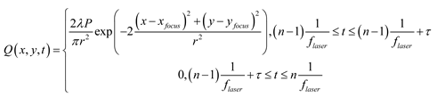
Where flaser denotes the pulsed laser frequency and τ denotes the pulse width.
The optical pulse duration is generally defined as the Full Width at Half Maximum (FWHM) of the laser power-time curve, i.e., the time span of a Gaussian pulse when its amplitude reaches half of the peak value, as shown in Figure 10a. A square wave function is used to replace the pulse width in the pulsed laser. To simulate the pulsed laser heat source, a periodic square wave function should be configured, which satisfies the condition that the value is 1 during the pulse width time and 0 for the rest of the time within one cycle. The laser frequency is set to 1 kHz, one pulse cycle is 1 ms, and the pulse width is 0.2 ms. The waveform of the square wave function is illustrated in Figure 10b.
The temperature change of the material during laser irradiation is calculated according to the general heat transfer equation (8) [38]:
In the simulation, the material parameters and laser parameters used are listed in Table 4.
In temperature field distribution, the laser beam energy is absorbed by the material, generating a high temperature of over 2000 °C, when the pulsed laser irradiates the silicon carbide surface. Based on the mesh shown in Figure 11, material ablation is considered to occur when the temperature exceeds 2700 °C [38], and the corresponding mesh depresses. Since the energy of the pulsed laser beam follows a Gaussian distribution, a conical ablation crater is assumed to form on the surface. From the isotherm distribution diagram, it is found that the high-temperature region generated by the material absorbing laser beam energy is mainly concentrated in a semicircular area with a radius of 50 μm centered at the laser focal point, while the temperature of other regions is less affected by the laser heat source.
A comparison between the cylindrical ablation crater generated in the simulation results and that measured in the laser irradiation experiment, shown in Figure 11a,b, reveals that both have the same morphological characteristics, which is of an arc shape with a deeper center and shallower sides, where it corresponds to the energy distribution pattern of the Gaussian heat source. The calculation process of parameter h is shown in the Section 4.2, where h was compared with experimental results of TCL and HAZ shown in Figure 12.
4.2. Dimension of TCL
Crack Initiation Criterion: Balance between thermal stress and fracture toughness. Experimental results show that the radial crack scale is much larger than the laser melting scale. When analyzing the crack region, material phase changes are neglected. For ease of calculation, the thermal expansion coefficient is assumed to be constant. Brittle materials have poor thermal conductivity, and the temperature gradient generated by laser heating causes uneven thermal expansion, which in turn induces thermal stress. Based on the theory of thermoelasticity, the model consists of two parts: stress calculation and crack initiation criterion. The material is assumed to be linearly elastic and isotropic, and thermal stress is generated by "free expansion caused by temperature change and material constraint." For a semi-infinite material heated by a circular laser spot, the radial stress σr, hoop stress σθ, and axial stress σz are the main components.
Among them, the hoop stress is the key factor inducing radial cracks, and its distribution on the surface (z=0) is expressed as:
where s is the integral variable corresponding to the radial position. When r < r0 (inside the laser spot), the thermal expansion of the material is constrained by the surrounding area, generating compressive stress. When r > r0 (outside the laser spot), the unexpanded material is constrained by the internal region, resulting in tensile stress and the tensile stress concentration area is the core region for crack initiation.
When the stress intensity factor KI induced by thermal stress at material defects (such as microcracks and impurities) reaches the fracture toughness KIc of the material, cracks initiate and propagate. The core criterion is expressed as:
For surface semi-elliptical cracks (a common crack topography induced by laser heating), the calculation formula for the stress intensity factor is expressed as:
where: σ is the maximum tensile stress at the crack tip, a is half the crack length, a = 1e-6m, 1.12 is the shape factor of the semi-elliptical crack, and =4.5 MPa·m1/2.
5. Conclusions
The material properties of silicon carbide SiC ceramics changes after laser irradiation, with multiple research sides considered such as surface/subsurface cracks, surface hardness, phase composition, laser-modified layer depth, and surface topography of the laser-modified SiC ceramics.
The order of influence of laser process parameters on the surface crack dimension of SiC ceramics is: laser power (indexed by current) > scanning times > defocus value > spot spacing. Additionally, the surface hardness of laser-modified SiC increases with the increase in laser current and number of scanning passes, while decreasing with the increase in defocus amount and spot spacing, with a maximum reduction of 8.2%.
A large amount of SiO₂ oxide layer is formed on the SiC surface after laser irradiation, with clear ablation groove boundaries. The width of the oxide layer increases with the increase in laser power and times of scanning passes, and decreases with the increase in defocus value and spot spacing. The SiO₂ formed by oxidation has a lower hardness but higher fracture toughness than the SiC phase, which is conducive to improving the grinding conditions of SiC.
Laser irradiation results in the formation of a melting zone, a thermal cracks layer, and a HAZ. The thicknesses of both the thermal cracks layer and HAZ increase with the increase in laser power and scanning times, and decrease with the increase in defocus value and spot spacing. Cracks are concentrated in the laser-modified layer. The maximum depth of the oxide layer reaches 20.13 μm, the laser-modified layer reaches 41.21 μm, and the laser HAZ reaches 53.84 μm.
Acknowledgments
Financial supports from the National Natural Science Foundation of China (GrantsNo. 52575478 is gratefully acknowledged.
References
- Wang, L.; Gao, Y.; Li, X.; Pu, T.; Yin, Y. Analytical Prediction of Subsurface Microcrack Damage Depth in Diamond Wire Sawing Silicon Crystal. Materials Science in Semiconductor Processing 2020, 112105015. [Google Scholar] [CrossRef]
- Zhang, L.; Chen, P.; An, T.; Dai, Y.; Qin, F. Analytical Prediction for Depth of Subsurface Damage in Silicon Wafer Due to Self-Rotating Grinding Process. Current Applied Physics 2019, 19, 570–581. [Google Scholar] [CrossRef]
- Li, H.N.; Yu, T.B.; Zhu, L.D.; Wang, W.S. Analytical Modeling of Grinding Induced Subsurface Damage in Monocrystalline Silicon. Materials & Design 2017, 130, 250–262. [Google Scholar] [CrossRef]
- Sun, J.; Qin, F.; Chen, P.; An, T. A Predictive Model of Grinding Force in Silicon Wafer Self-Rotating Grinding. International Journal of Machine Tools and Manufacture 2016, 109, 74–86. [Google Scholar] [CrossRef]
- Lawn, B.; Wilshaw, R. Indentation Fracture: Principles and Applications. Journal of Materials Science 1975, 10, 1049–1065. [Google Scholar] [CrossRef]
- Kizaki, T.; Ogasahara, T.; Sugita, N.; Mitsuishi, M. Ultraviolet-laser-assisted precision cutting of yttria-stabilized tetragonal zirconia polycrystal. Journal of Materials Processing Technology 2014, 214, 267–275. [Google Scholar] [CrossRef]
- Azarhoushang, B.; Soltani, B.; Zahedi, A. Laser-assisted grinding of silicon nitride by picosecond laser. The International Journal of Advanced Manufacturing Technology 2017, 93, 2517–2529. [Google Scholar] [CrossRef]
- Hao, J.X.; Ma, S.Y.; Luo, H.Q. Machinability of reaction-bonded silicon carbide by applying in-situ laser-vibration hybrid assisted diamond cutting. Ceramics International 2025, 51, 42961–42972. [Google Scholar] [CrossRef]
- Fu, Y.F.; Zhang, J.G.; Chen, X. Defect suppression mechanism for laser in-situ assisted diamond cutting of reaction-bonded silicon carbide; Huazhong University of Science and Technology (China); Hubei University of Technology (China), 2023. [Google Scholar] [CrossRef]
- Zhang, J.G.Z.; Fu, Y.F.; Yu, Y.J. Subsurface deformation and crack propagation between 3C-SiC/6H-SiC interface by applying in-situ laser-assisted diamond cutting RB-SiC. Materials Letters 2023, 336. [Google Scholar] [CrossRef]
- Kumar, M.; Melkote, S.; Lahoti, G. Laser-assisted microgrinding of ceramics. CIRP Annals-Manufacturing Technology 2011, 60, 367–370. [Google Scholar] [CrossRef]
- Xu, S.; Yao, Z.; Zhang, M. Material removal behavior in scratching of zirconia ceramic surface treated with laser thermal shock. International Journal of Advanced Manufacturing Technology 2016, 85, 2693–2701. [Google Scholar] [CrossRef]
- Cao, C.; Zhao, Y.G.; Zhang, G.G. Experimental study of plastic cutting in laser-assisted machining of SiC ceramics. Optics and Laser Technology 2024, 169. [Google Scholar] [CrossRef]
- Lin, J.Q.; Kang, M.S.; Gu, Y. Wear mechanism analysis of PCD tools during the cutting process of SiCp/Al with a 45% volume fraction using nanosecond pulsed laser-assisted cutting. International Journal of Advanced Manufacturing Technology 2025, 138, 5645–5662. [Google Scholar] [CrossRef]
- Agarwal, S.; Rao, P.V. Experimental investigation of surface/subsurface damage formation and material removal mechanisms in SiC grinding. International Journal Machine Tools Manufacture 2008, 48, 698–710. [Google Scholar] [CrossRef]
- Groeb, M.; Catrin, R.; Groeb, J. Hybrid laser and subtractive machining of reaction bonded silicon carbide. Laser Metrology and Machine Performance XV - 15th International Conference and Exhibition on Laser Metrology Machine Tool, CMM and Robotic Performance; 2023; 1, pp. 95–101. [Google Scholar]
- Zhang, W.; Liu, T.; He, J.L. Full Dicing of Ultra-thin Silicon Carbide Substrate by Femtosecond Laser. Surface Technology 2023, 52, 306–313. [Google Scholar]
- Kong, X.J.K.; Liu, S.W.; Ning, H. Cutting performance and tool wear in laser-assisted grinding of SiC/SiC ceramic matrix composites. Materials Research Express 2022, 9. [Google Scholar] [CrossRef]
- Yang, H.Y.; Fu, M.; Zhang, X.; Zhu, K. Material Removal Mechanisms of Polycrystalline Silicon Carbide Ceramic Cut by a Diamond Wire Saw. Materials 2024, 17, 4238–4249. [Google Scholar] [CrossRef] [PubMed]
- Qian, W.; Zhao, G.; Yang, H.; Nian, Z. Combined hybrid machining of laser ablation-drilling small holes in Cf/SiC composites. Ceramics International 2024, 50, 55892–55905. [Google Scholar] [CrossRef]
- Zhang, F.Y.; Sun, S.F.; Wang, Xi. Research on the ablation mechanism and feasibility of UV laser drilling to improve the machining quality of 2.5D SiC/SiC composites. Optics and Laser Technology 2025, 181, 111754. [Google Scholar] [CrossRef]
- Xu, S.; Yao, Z.Q.; He, J.W.; Xu, J. Grinding characteristics, material removal and damage formation mechanisms of zirconia ceramics in hybrid laser/grinding (HLG). Journal of Manufacturing Science and Engineering 2018, MANU-17-1199. [Google Scholar]
- Erdenechimeg, K.; Jeong, H.; Lee, C. A Study on the Laser-Assisted Machining of Carbon Fiber Reinforced Silicon Carbide. Materials 2019, 12, 2061–2061. [Google Scholar] [CrossRef] [PubMed]
- Zhang, J.; Liu, Z.; Zhang, Y. High-Power Femtosecond Laser Processing of SiC Ceramics with Optimized Material Removal Rate. Micromachines 2023, 14, 1960. [Google Scholar] [CrossRef]
- Zhao, G.L.; Xia, H.J.; Zhang, Y.; Li, L. Laser-induced oxidation assisted micro milling of high aspect ratio microgroove on WC-Co cemented carbide. Chinese Journal of Aeronautics 2021, 34, 465–475. [Google Scholar] [CrossRef]
- Dai, D.; Cai, Y.K.; Zhao, Y.G. Study on the plastic removal behavior of SiC ceramic materials in laser-assisted high -temperature turning. Optics and Laser Technology 2025, 192, 113566–113566. [Google Scholar] [CrossRef]
- Li, S.; Chen, P.; Qin, F. The separation mechanism of 4H-SiC dicing by continuous laser. 23rd International Conference on Electronic Packaging Technology (ICEPT), Dalian, China; 2022. [Google Scholar]
- Li, J.C.; Wang, J.Q.; Chen, G.J. Thermal modification and material removal mechanism of C/SiC composites in laser-ultrasonic hybrid machining. Journal of the European Ceramic Society 2025, 45, 117664–117664. [Google Scholar] [CrossRef]
- Ma, Z.; Wang, Q.; Chen, H. A grinding force predictive model and experimental validation for the laser-assisted grinding (LAG) process of zirconia ceramic. Journal of Materials Processing Technology 2022, 302, 117492. [Google Scholar] [CrossRef]
- Li, Z.; Zhang, F.; Luo, X. Material removal mechanism of laser-assisted grinding of RB-SiC ceramics and process optimization. Journal of the European Ceramic Society 2019, 39, 705–717. [Google Scholar] [CrossRef]
- Rao, X.; Zhang, F.; Luo, X. Material removal mode and friction behaviour of RB-SiC ceramics during scratching at elevated temperatures. Journal of the European Ceramic Society 2019, 39, 3534–3545. [Google Scholar] [CrossRef]
- Zhang, Q.; Zhao, Q.; To, S. Diamond wheel wear mechanism and its impact on the surface generation in parallel diamond grinding of RB-SiC/Si. Diamond and Related Materials 2017, 74, 16–23. [Google Scholar] [CrossRef]
- Zhang, Q.; Zhang, Z.; Su, H. Role of Si in the surface damage mechanism of RB-SiC/Si under mechanical loading. Journal of Materials Engineering and Performance 2019, 28, 254–262. [Google Scholar] [CrossRef]
- Li, Z; Zhang, F.; Luo, X. Subsurface damages beneath fracture pits of reaction-bonded silicon carbide after ultra-precision grinding. Applied Surface Science 2018, 448, 341–350. [Google Scholar] [CrossRef]
- Chen, M.; Dai, H. Molecular dynamics study on grinding mechanism of polycrystalline silicon carbide. Diamond and Related Materials 2022, 130, 109541. [Google Scholar] [CrossRef]
- Wu, M.; Guo, B.; Zhao, Q. High efficiency precision grinding of micro-structured SiC surface using laser micro-structured coarse-grain diamond grinding wheel. International Journal of Precision Engineering and Manufacturing-Green Technology 2019, 6, 577–586. [Google Scholar] [CrossRef]
- Yin, G.; Yang, L.; Niu, T. Study on the removal mechanism of 4H-SiC materials based on single grain grinding and optimization of process parameters. Journal of the Brazilian Society of Mechanical Sciences and Engineering 2025, 47, 1–14. [Google Scholar] [CrossRef]
- Qu, S.; Wei, C.; Yang, Y. Grinding mechanism and surface quality evaluation strategy of single crystal 4H-SiC. Tribology International 2024, 194, 109515. [Google Scholar] [CrossRef]
- Temmler, A.; Braun, K.; Uluz, E. Heat accumulation and surface roughness evolution in CO2 nanosecond laser ablation of quartz glass. Optics & Laser Technology 2021, 144, 107426. [Google Scholar] [CrossRef]
Figure 1.
Schematic diagram of laser-modified SiC ceramic. (a) scanning strategy. (b) positive defocus processing.
Figure 1.
Schematic diagram of laser-modified SiC ceramic. (a) scanning strategy. (b) positive defocus processing.
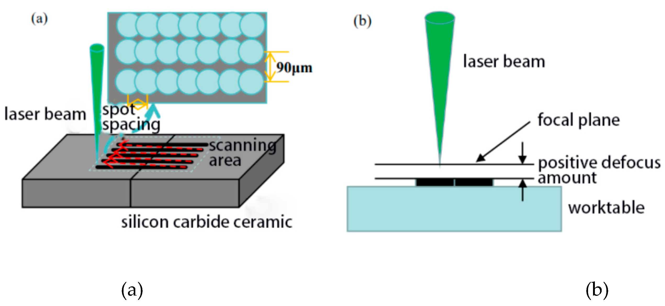
Figure 3.
The grinding test bench and abrasive tool.
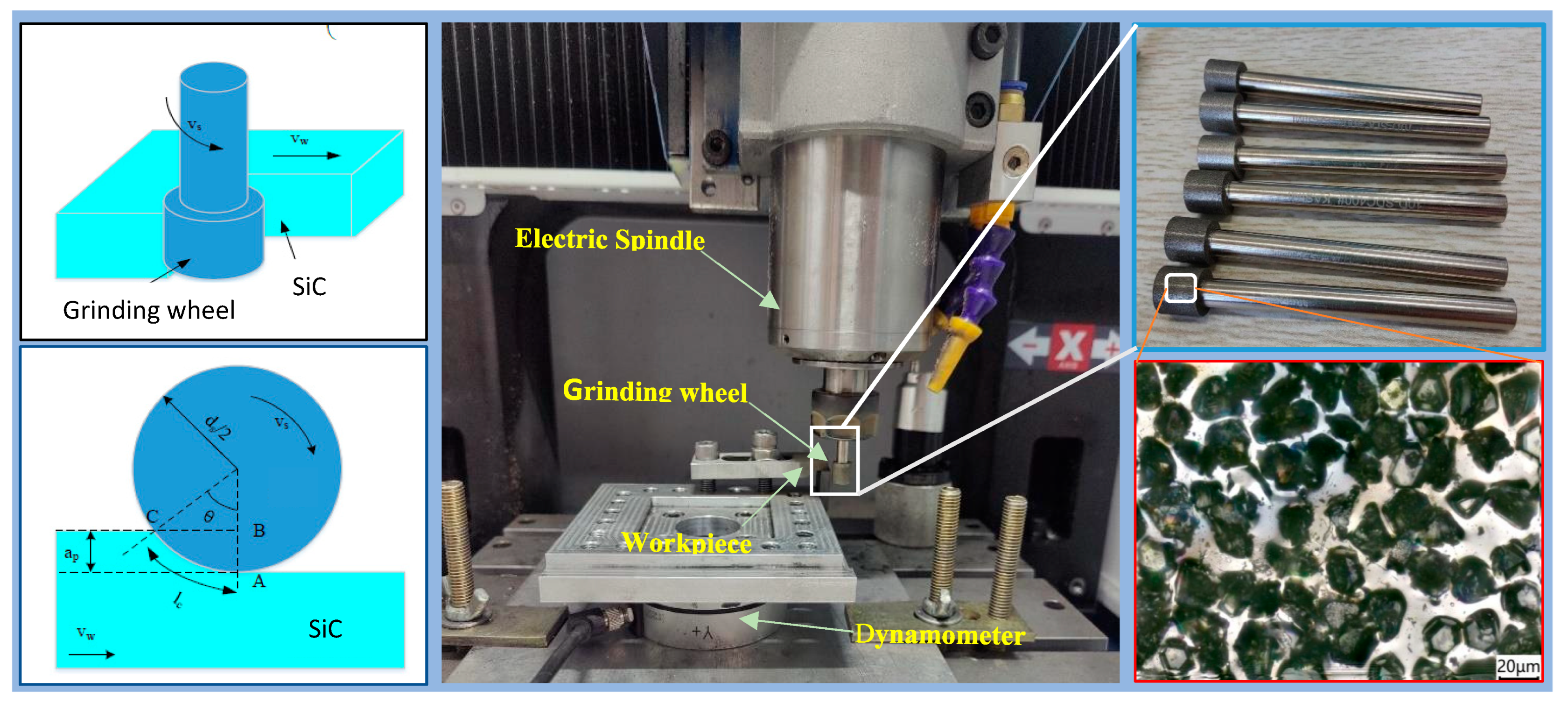
Figure 4.
(a) surface topography of laser modified SiC ceramics. (b) local magnification of a.(c) cross-section of a. (d) 3D topography from super-depth microscope (e) cross-section of none-grinding surface.
Figure 4.
(a) surface topography of laser modified SiC ceramics. (b) local magnification of a.(c) cross-section of a. (d) 3D topography from super-depth microscope (e) cross-section of none-grinding surface.
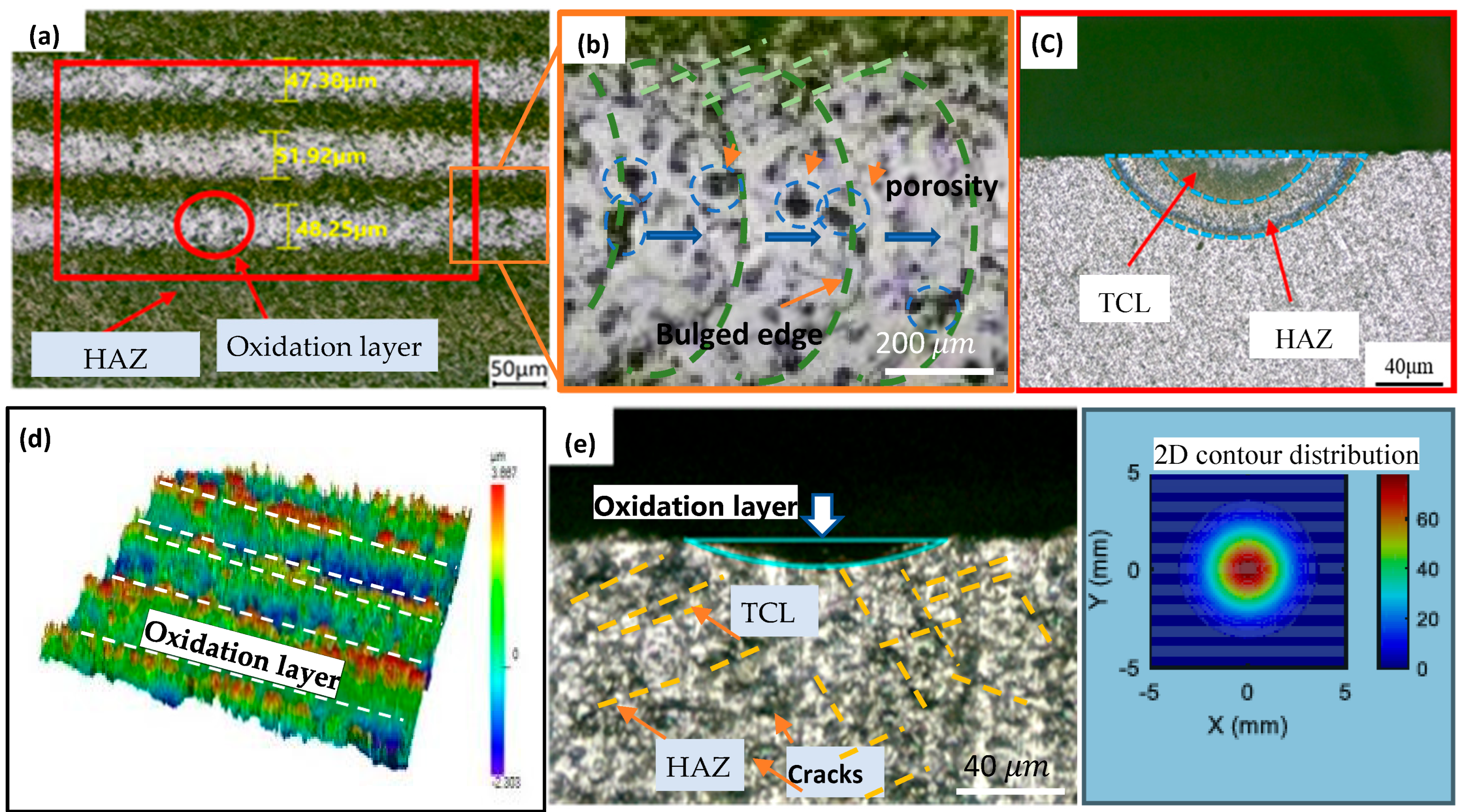
Figure 6.
(a) The plot of (indexed by current) on HV of laser modified area. (b) Plot of scan times vs hardness of laser modified area.
Figure 6.
(a) The plot of (indexed by current) on HV of laser modified area. (b) Plot of scan times vs hardness of laser modified area.
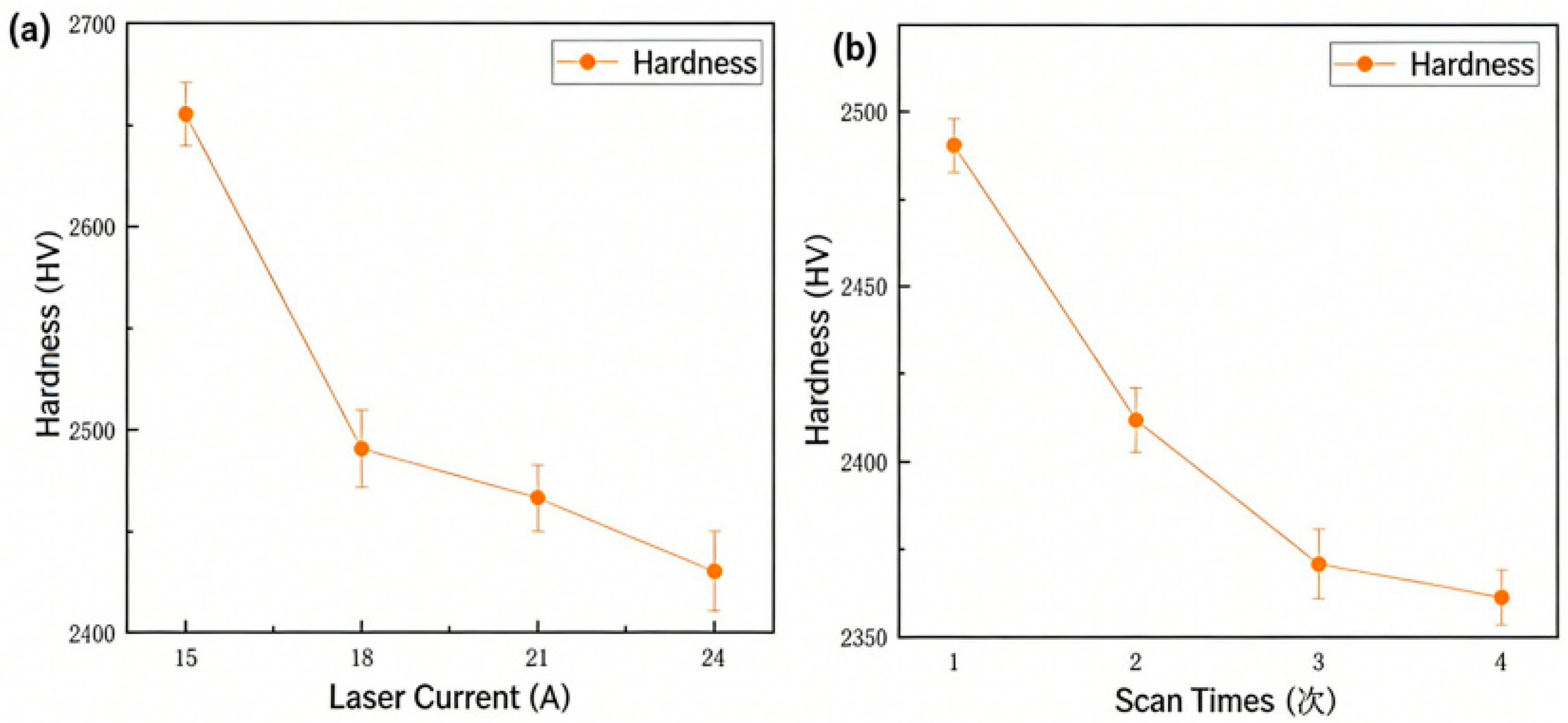
Figure 7.
(a) Topography of SiC sample; (b) XRD Spectra of Silicon Carbide Ceramics after Laser Modification; (c)XRD Spectra of Silicon Carbide Ceramics before Laser Modification; (d) The correlation between Ra and laser current.
Figure 7.
(a) Topography of SiC sample; (b) XRD Spectra of Silicon Carbide Ceramics after Laser Modification; (c)XRD Spectra of Silicon Carbide Ceramics before Laser Modification; (d) The correlation between Ra and laser current.
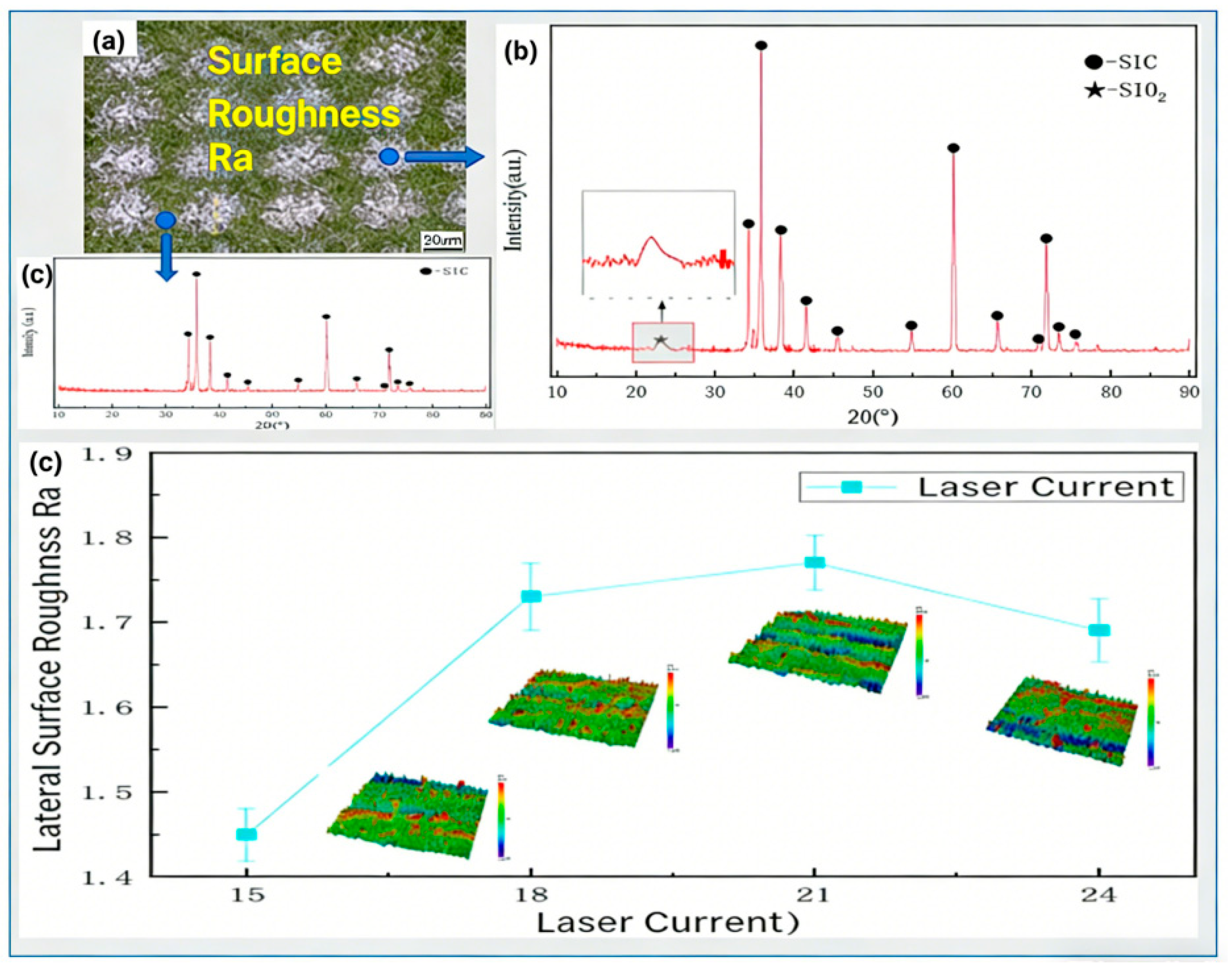
Figure 8.
(a) SEM topography of the lapping surface; (b) The effect of Laser Power on Fn. (c) The effect of Laser Power on Ft.
Figure 8.
(a) SEM topography of the lapping surface; (b) The effect of Laser Power on Fn. (c) The effect of Laser Power on Ft.
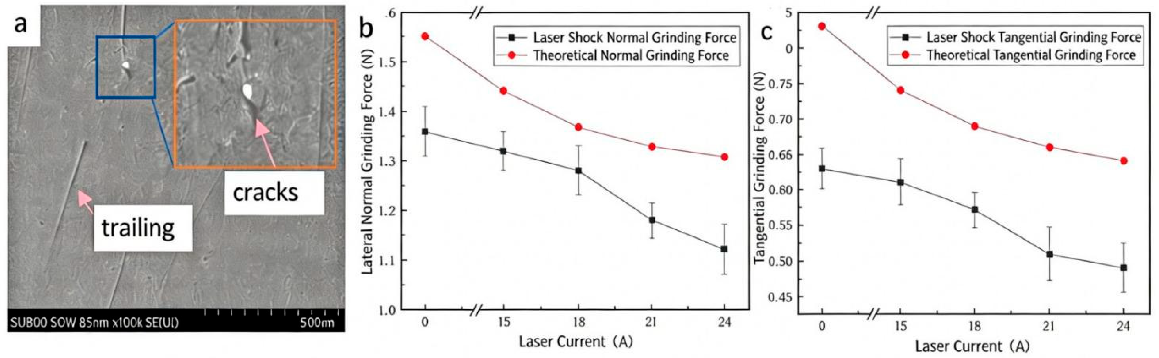
Figure 9.
(a) SEM topography of the lapping surface; (b) The effect of vsr on Fn; (c) The effect of Laser Power on Ft.
Figure 9.
(a) SEM topography of the lapping surface; (b) The effect of vsr on Fn; (c) The effect of Laser Power on Ft.
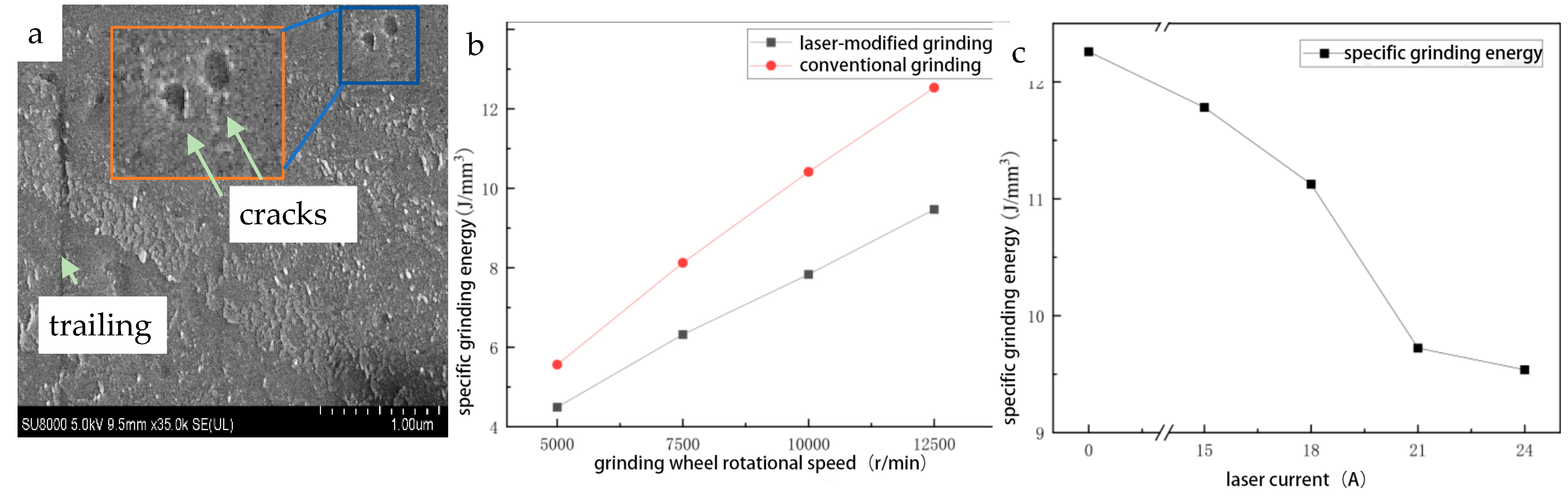
Figure 10.
Laser Source Characteristics. (a) the time span of a Gaussian pulse. (b)the waveform of the square wave function.
Figure 10.
Laser Source Characteristics. (a) the time span of a Gaussian pulse. (b)the waveform of the square wave function.
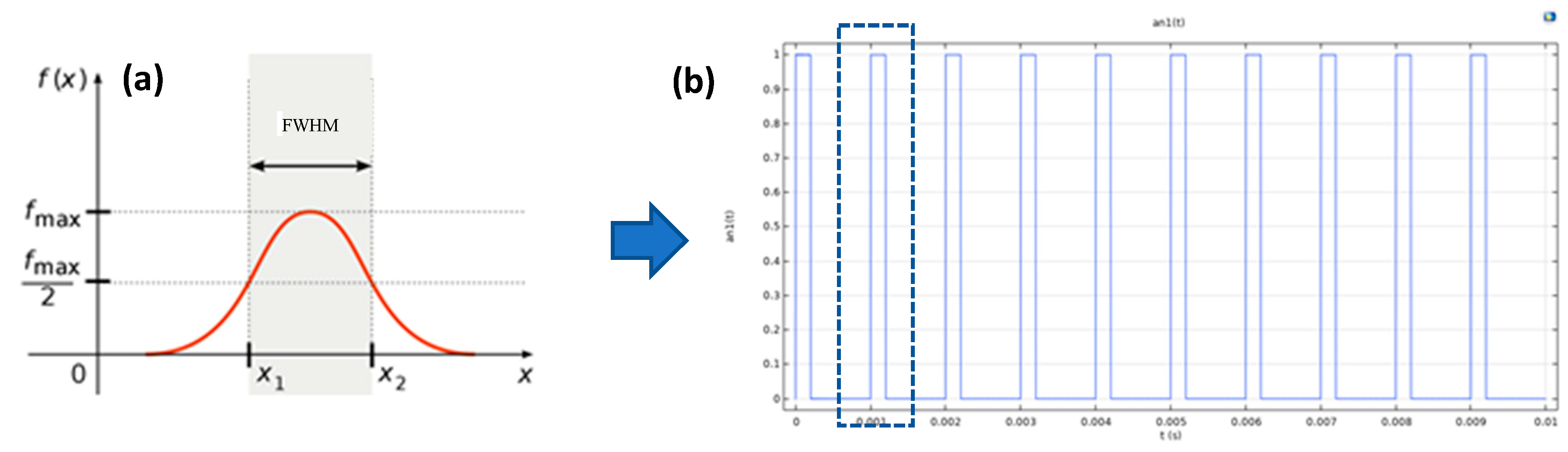
Figure 11.
Simulation of laser irradiation on SiC surface indexed by time. (a) Thermal field distribution. (b) Sample correlation with (a).
Figure 11.
Simulation of laser irradiation on SiC surface indexed by time. (a) Thermal field distribution. (b) Sample correlation with (a).
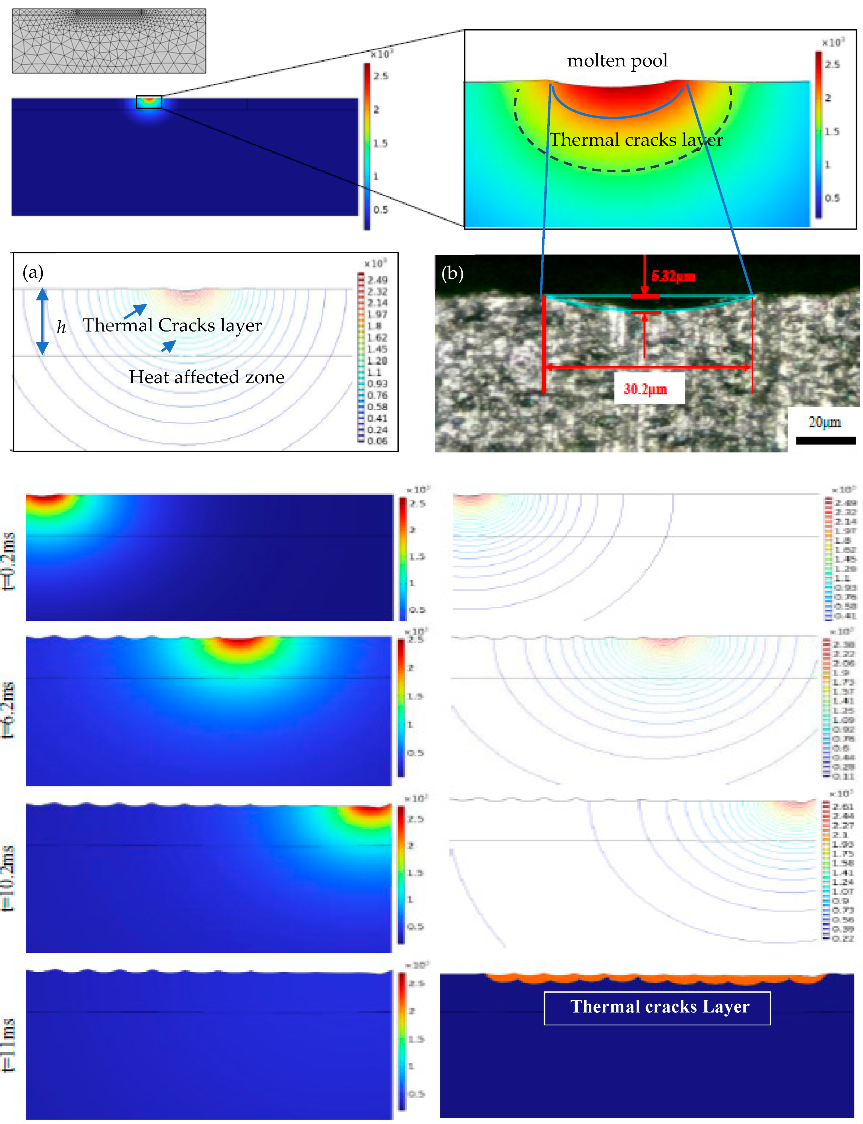
Figure 12.
Dimension of the TCL and HAZ. (a) Plot of laser power vs dimension of TCL, HAZ and theoretical calculated value. (b) Plot of scanning times vs dimension of TCL, HAZ and theoretical calculated value. (c) Plot of laser spot spacing vs dimension of TCL, HAZ and theoretical calculated value.
Figure 12.
Dimension of the TCL and HAZ. (a) Plot of laser power vs dimension of TCL, HAZ and theoretical calculated value. (b) Plot of scanning times vs dimension of TCL, HAZ and theoretical calculated value. (c) Plot of laser spot spacing vs dimension of TCL, HAZ and theoretical calculated value.
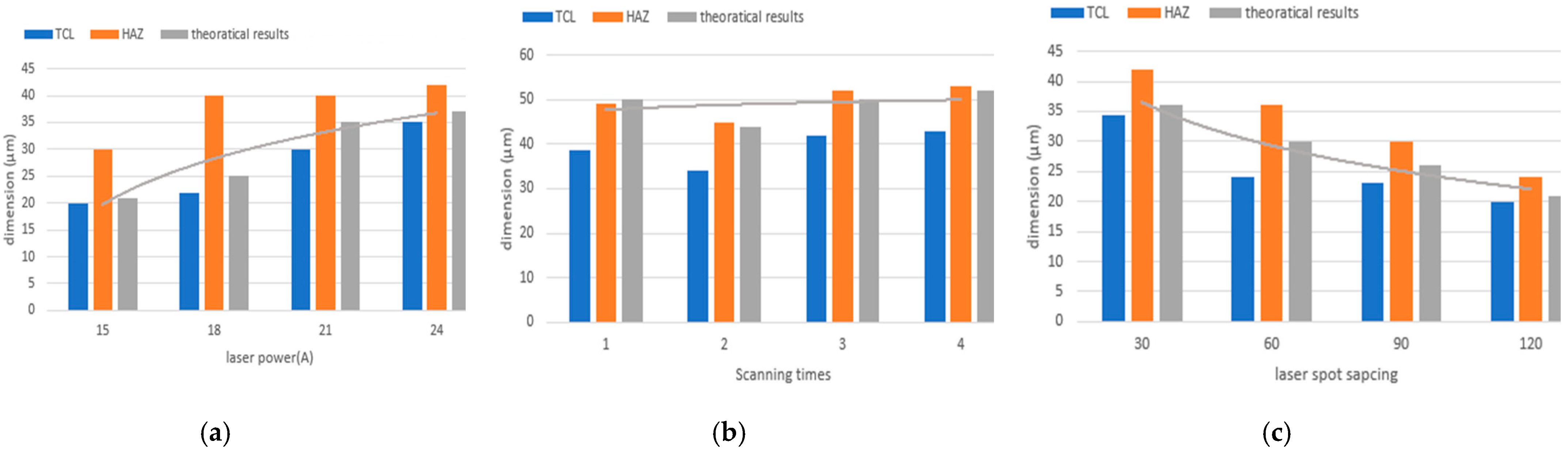
Table 2.
Main Technical Parameters of Laser Engraving Machine.
| parameters | values |
|---|---|
| Wavelength λ (nm) | 532 |
| Beam diameter D (μm) | 50 |
| Maximum scanning speed V (points/s) | 1000 |
| Maximum output power P (W) | 5 |
| Frequency f (kHz) | 1 |
| Single-pulse energy Q (mJ) | 2.5 |
| Maximum scanning area S (mm2) | 90× 90× 90 |
Table 3.
Main Grinding Parameters of Laser Surface-Modified SiC.
| parameters | values |
|---|---|
| Wheel speed Vsr, r/min | 5000,7500,10000,15000 |
| Worktable speed Vw, mm/min | 2.5,5,7,10 |
| Grinding wheel | Electroplated diamond |
| Grain size, μm | 38 |
Table 4.
The material parameters and laser parameters.
| parameters | values |
|---|---|
| Spot Radius (μm) | 45 |
| Scanning Speed (mm/s) | 60 |
| Melting Point (℃) | 2700 |
| Heat of Sublimation (kJ/kg) | 11562.5 |
| Density (kg/m³) | 3200 |
| Laser Frequency (kHz) | 1 |
| Pulse Width (s) | 0.0002 |
| Surface Emissivity | 0.79 |
| Thermal Conductivity (W/(m·K)) | 236 |
| Constant-Pressure Specific Heat Capacity (J/(kg·K)) | 680 |
| Ambient Temperature (℃) | 20 |
Disclaimer/Publisher’s Note: The statements, opinions and data contained in all publications are solely those of the individual author(s) and contributor(s) and not of MDPI and/or the editor(s). MDPI and/or the editor(s) disclaim responsibility for any injury to people or property resulting from any ideas, methods, instructions or products referred to in the content. |
© 2026 by the authors. Licensee MDPI, Basel, Switzerland. This article is an open access article distributed under the terms and conditions of the Creative Commons Attribution (CC BY) license (http://creativecommons.org/licenses/by/4.0/).
Copyright: This open access article is published under a Creative Commons CC BY 4.0 license, which permit the free download, distribution, and reuse, provided that the author and preprint are cited in any reuse.


