
Submitted:
19 December 2025
Posted:
22 December 2025
You are already at the latest version
Abstract
Drones have long been explored for supply. While several systems offering small pay-loads in drone delivery have seen operational use, large-scale supply drones have yet to be adopted. A range of setbacks cause this, including technological and operational challenges that hinder their adoption. Here, these challenges are evaluated from a conceptual modelling perspective to forecast their applicability once these barriers are overcome. The study uses technology trend modelling and bibliometric activity map-ping methodologies to predict the applicability of specific technologies that are cur-rently identified as operational challenges. Specifically for supply drones, trends in technological improvements of battery technology and aircraft control are modelled to project effects and focus on landing zone autonomy and powertrain. The prediction also focuses on the current state of hybrid power and higher levels of automation required for landing zone operations. These models are validated through several published case studies of small delivery drones and then applied to assess the feasibility and con-straints of larger supply drones. A case study, conceptual design of a supply drone large enough to move a shipping container, is presented to illustrate the critical technologies required to transition large supply drones from concept to operational reality. Key technologies required for large-scale supply drones have yet to build up a critical mass of research activity, particularly on landing zone autonomy and powertrain. Moreover, additional constraints beyond technological and operational challenges could include limitations in autonomy, certification hurdles, regulatory complexity, and the need for greater social trust and acceptance.
Keywords:
supply drone
; autonomous drones
; airspace regulation
; drone certification
1. Introduction
Supply drones have been in development for over six decades, at both small and large scales [1,2,3,4,5]. Their business case is sound: reduced human intervention, timely delivery, efficiency, improved safety, automating the supply chain, reducing cost, etc. [2]. And their impact will be profound once the technology scales.
The first uncrewed helicopter, the Gyrodyne QH-50 Helicopter, first flew in 1960 and demonstrated the potential for rescue and spare parts delivery. In the mid-2000s, Kaman, in collaboration with Lockheed Martin, began pursuing an unmanned version of their K-MAX helicopter. The goal was to create an optionally piloted or fully autonomous cargo delivery system. The project was driven by the need to reduce risk to personnel in dangerous environments and to perform supply missions more efficiently. The first unmanned flights demonstrated the unmanned K-MAX's capabilities in 2008, successfully demonstrating take-off, landing, and cargo delivery [6]. Later that year, it showed it could automatically land and drop a 3,000-kilogram load. A pair of unmanned K-MAX helicopters was deployed for an extended evaluation between 2011 and 2014 [7].
In 2022, a UH-60A Black Hawk helicopter, retrofitted with a Sikorsky's optionally-piloted system, made its first flight without any crew onboard [8,9]. In 2025, Sikorsky announced that it had continued this development [10] to build an uncrewed UH-60L [11]. A Black Hawk can lift 10,000 kilograms of payload. K-MAX and Black Hawk are ‘medium lift’ helicopters, where medium lift is defined as between 1,000 and 10,000 kilograms of payload.
At the small-scale end of uncrewed supply aircraft, there are several historical examples of commercial success. In 2013, a multinational supply company delivered medicine using their Parcelcopter [12]. In short succession, a range of other examples followed, such as Google Wing, Amazon Prime Air, and Zipline [13], with all three commencing initial operations in the period 2014 to 2016. Small parcel delivery systems are designed to stay under a maximum take-off weight of 25 kilograms to conform to EASA and FAA categorisations and regulations, resulting in their payloads generally being less than 10 kilograms.
The success of fleets of these small parcel delivery was predicated on the maturing of several technology areas, including the development of more powerful and lighter lithium-ion batteries and solving the battery charging optimisation problem circa 2018 [14,15]. Moreover, in 2017, small parcel delivery adopted automated flight controls, including improved avionics, fly-by-wire systems, and optimised vehicle routing [12,16,17,18,19]. Critical on-board mechanics includes distributed electric propulsion formed by multiple electric motors and rotors, allowing for more stable and efficient vertical flight [20,21,22,23,24]. These drones were also made of lightweight materials such as carbon fibre and other composites.
In the few years since these breakthroughs, the set of primarily commercial technologies that make up small parcel delivery drones has taken revolutionary steps at a pace and scale of innovation and adaptation. Today’s parcel delivery services are made up of four key technology sub-sets: (1) lightweight airframes; (2) lightweight battery density enabled by solutions to the Battery-Charger Problem; and (3) multi-aircraft drone control systems and drone traffic management systems enabled by solutions to the Vehicle Routing Problem. To be applicable for a large supply drone, defined here as a drone that can move 500-1,000 kilograms of supplies at a time, these technologies need to be scaled up in size and capability. Evolution needs to occur across five key technology sub-sets [25]:
(1) autonomous flight operations integrated with traditional air traffic, including detect-and-avoid and sense-and-avoid technologies;
(2) autonomous landing zone operations (including sensing technologies for that role);
(3) powertrain developments commensurate to scaling to large supply roles, including hybrid-electric powerplants;
(4) regulation and certification; and
(5) social license and acceptance.
These last two technology sub-sets include the regulation of future autonomous weapons systems [26,27,28], their ethical considerations [29,30,31,32,33] and social acceptance by law-abiding countries. Social acceptance will be crucial for roles such as automated flying taxis and air ambulances.
To forecast the application of large supply drones, it is important to review and evaluate the key challenges. Here, the most crucial technological improvement is assessed to be battery technology and aircraft control, with the principal limiting effect being on landing zone autonomy and powertrain. Specifically, the prediction focuses on the current state of hybrid power and higher levels of automation required for landing zone operations, particularly full autonomy. Identifying these technologies and forecasting their future applicability requires understanding innovation trajectories over time. The revolution of small parcel delivery drones remains instructive, particularly on the lag in this sector between research breakthroughs and public use. These drone technologies are examined through literature review and literature mapping, industry engagement, and activity analysis. Key technologies are discussed to analyse how each technology has evolved, ultimately aiming to qualitatively discuss and better forecast the applicability of large supply drones. A case study conceptual design of a large-scale supply drone, the Dragonfly, is used to exemplify the effects of the key technological challenges. The case study illustrates the future dependencies on hybrid power, very large adaptive ducted fan developments, and autonomous control for the much higher power vertical takeoff and transition to and from forward flight.
2. Methodology
The technologies that led to the emergence of successful business models for small parcel delivery drones are products of academic and community bodies of knowledge developed over several decades. These systems are based on small drones used for photography in commercial roles and defence reconnaissance, scaled in the early 2000s, that could carry a small amount of additional payload. Role scaling led to the mainstream adoption of multi-rotor drones in the photography and real estate industries and to broader defence uses, and could be used to transport other equipment like envelopes, thumb drives, life vests, signal flares, etc. These aircraft were enabled by the maturity of miniaturised flight controllers, the reliability of batteries, and appropriate bandwidth data links.
Technological developments can be traced using a literature review software such as Litmaps© [34,35]. The Litmaps program uses artificial intelligence algorithms to identify related and relevant articles based on topic, author, publication location, and citation chaining [36], allowing a bibliometric review [37]. Most of the development and evolution in small parcel delivery supply drones has been undertaken predominantly by the commercial sector, with much recorded in academic publications. However, to understand the nuances of commercial application from theoretical knowledge and to forecast and model the technology's readiness with recency, it is essential to track recent and contemporary developments through bibliometric analysis and industry fora. Such artifacts can be tracked and linked within the same Litmaps analysis databases, thereby extending documented research trends.
To bring small parcel delivery drones to maturity, the primary problems that needed to be solved were the vehicle routing problem [12,16,17,18,19] and the Battery-Charger Problem [14,15]. The commercial adoption of parcel delivery drones occurred once these problems were solved. Since then, the rates of industrial development and evolution in parcel delivery drones have significantly increased and outpaced academic technical publications. To forecast the technology's readiness, it is essential to track recent and contemporary industry developments. In Australia, where drone technology developments and innovation are mature, industry engagement is a valid method for exploring, scrutinising, and validating industry claims and publications. Notably, one of the most advanced small parcel delivery services, Google’s Wing, was pioneered in Australia; another delivery service, Swoop Aero, was also based in Australia; and the most used flight controller for experimental drones, ArduPilot, is also Australian. Hence, the domestic industry was engaged to scrutinize and then extrapolate the key technologies of parcel delivery drones.
The methodology is first confirmed using predominantly small parcel delivery drone technologies, which is then expanded to include key areas of large-scale supply drone. The technical papers can be categorised by the technology set and the subsets they explore, and the bibliometric analysis software can show the relative importance of each paper and quantify its impact based on citation count. Our mapping likely correlates with the maturity of a technology set or subset, enabling, with the appreciation of any likely lag, the forecasting of future technology readiness [37,38,39].
The Litmaps maps are presented chronologically along the x-axis and citation count along the y-axis. To illustrate the relevance of citation count, the circles also increase in size in proportion to their citation counts. The plots are not linear: Litmaps uses a logarithmic scale that optimises the format for reader presentation.
An overview of a case study, the conceptual design of a large-scale supply drone, Dragonfly, is provided to illustrate the effect of the current technological limitations on the highly integrated aircraft design challenge. Requirements are evolved through two initial conceptual design iterations, using limited morphology, statistical weight estimation, and initial rotor sizing, predominantly using the general aviation aircraft methods by Gudmundsson [40] augmented as necessary to account for vertical take-off. The case study includes limited flight simulation and computational fluid dynamics to inform subsequent design iterations. While the Dragonfly design report is unpublished [41], the authors have agreed to provide it upon request to the corresponding author of this article.
3. Analysing Supply Drone Technology Readiness
Small supply drones arguably gained their social license and acceptance, not due to a technology or commercial milestone, but due to the global pandemic of 2020, which forced much of the world into accepting the benefits of small parcel delivery [42,43,44,45]. Thus, although not without contention, small parcel delivery has become a ubiquitous element of modern economics. Additionally, lightweight structural material for aircraft was pioneered in the 1980s [46,47,48,49] and was therefore already a very mature technology field by the time that small supply drones needed composite airframes. This section explores key technological and operational readiness of large-scale supply drones.
3.1. Battery-Charger Problem for Drones
To realise an effective drone delivery service for small products, an optimal path-planning tool is essential for operational efficiency. A key limitation are the batteries and recharging stations required in large urban areas to complete delivery schedules. A new coverage model was needed that could optimise the location of recharging stations for delivery drones, based on continuous space shortest paths [15]. In parallel, research into battery management of such applications was required to formulate an optimisation problem based on battery assignment and battery scheduling, which prospective business operators could apply [14]. These algorithmic breakthroughs were undertaken in the period 2014-18 by Hong and Park, and when combined with business operational strategies and hardware innovations, they turned theoretical math problems into 24-hour multi-aircraft operations that yielded commercial reality. Hong and Park’s work was impactful, with citations peaking in 2020-2023. Notably, this was around the same time that successful operators like Wing were upgrading their battery-induction charging systems and scaling up their operations following commercial successes during the 2020 pandemic. With these algorithmic problems solved, future efficiencies in small parcel delivery drones would largely be limited to increasing the power density of their lightweight batteries.
3.2. Vehicle Routing Problem for Drones
The vehicle routing problem for drones extends the classic ‘Travelling Salesman Problem’. It asks: How do we coordinate a fleet of drones (often working alongside trucks) to deliver packages to a set of customers in the most efficient way possible?[16] The algorithmic breakthroughs were undertaken in the period 2014-18. The vehicle routing problem for drones is mathematically more complex than standard routing because drones have strict physical limits that trucks do not: drones cannot fly all day on a tank of gas, cannot move many packages like a truck can, have to consider the altitude dimension of airspace (and wind/weather), and must return frequently to the depot to reload and recharge. To address these routing issues, researchers developed new algorithmic classes since the ‘Brute Force’ method of checking every possible route is inefficient, especially for edge computing.
To solve the routing problem, three main algorithmic strategies were developed. The first is the ‘Flying Sidekick’ Model of tandem routing, where a truck acts as a mobile aircraft carrier [16]. The second strategy was one of ‘Cluster-First, Route-Second’, where algorithms first group customers into geographic ’clusters’ that fit within a single drone's battery radius. The drone services a cluster, then returns to base. Breaking one large problem into many small solvable ones defines operational solutions like hub-and-spoke networks, where a central distribution centre launches drones on simple out-and-back radial trips, simplifying the routing problem significantly. The third strategy is ‘Weather-Aware Routing’, where advanced algorithms account for wind vectors, enabling flying with the wind to save battery [50].
The academic publications from the most impactful researchers of the mid-2010s can be seen in Figure 1. Three of them (Dorling [17], Agatz [18] and Otto [19]) recently peaked from 2022 and one (Murray [16]) remains to be annually cited in increasing numbers. Notably, the carriers Wing, Amazon Prime Air, and Zipline all founded and scaled their initial operations around the same time as this algorithmic work was being undertaken and published, aligned with the steady growth of the impact of these papers. Our observation is particularly important when considering the emergence of the key technologies that enable large-scale supply drones.
3.3. Landing Zone Autonomy
Small, commercial parcel delivery drones undertake landing operations with Global Positioning System (GPS) for location and with simple and cheap altitude sensors, predominantly developed commercially by the automotive industry. They can be simple because most operations are undertaken to and from well-surveyed, urban areas, and the delivery landing zone is prescribed to be a clear, flat area, usually a rooftop, driveway, or clear backyard. However, more robust landing control sensors are needed for remote and less surveyed delivery areas, particularly if GPS cannot be assured and alternative sites are needed clear from vegetation or other obstructions. Perception systems from autonomous ground vehicles, which have benefited from development since the 1970s [51,52,53,54,55], cannot be transplanted onto drones as aircraft are very weight sensitive and usually need much longer ranges than those of cars. As such, more remote supply drone landing zone operations need to be highly automated or semi-autonomous and augmented by multi-sensor terrain profiling. The field is not yet mature, despite there being a range of academic sources over the past two decades [56,57,58,59,60,61,62,63], as seen in Figure 2.
Our analysis reveals that publications are scarce and have a low impact, with the highest achieving only ~230 citations. None of the highest cited works show a citation pattern that indicates that they were ‘breakthrough’ research, as discussed by Faidi [37]. There must be additional, unpublished research occurring within non-public research institutions, such as internal research and development within aerospace companies, that is not being shared to retain ownership of the intellectual property of any breakthroughs. The motives for this are understood, but are noted as a likely significant cost factor compared to the more rapid development of this technology by a global research community.
Global, open-source research has been pointed out as a contributor to the successes of other autonomy technology developments over the past 20 years [22,64,65,66,67]. The development of landing zone autonomy for large supply drones will likely remain slow until the status quo changes. It is only with a significant, open, and prolonged investment in the development and integration of autonomy sensing systems that the challenges described above can be solved. Applying traditional, physical, and government acquisition approaches could mean it is not achieved until the 2030s at the earliest. Initiatives like the Government Reference Architecture for Autonomy (A-GRA) could assist in this area, but are still under development by public-private partnerships focused on enabling prototyping of a large, electric supply and passenger aircraft [68,69,70]. Thus, the journey towards fully autonomous large-scale supply drones still has a long way to go, as there remains a dearth of academic effort towards completing design reference architectures.
3.4. Powertrain
Batteries alone cannot yet power a large supply drone over the distances that are needed to move large quantities of heavy parcels for commercial package delivery agencies, paying passengers for commercial taxi companies, patients for air ambulances, or supplies for remote operations [71]. For this reason, a significant body of research has gone into hybrid-electric [72,73,74] and fuel cell [75,76,77] powerplants, with a considerable focus on hydrogen. Hydrogen provides distinct advantages of high power, long-range endurance, quieter operations, and zero emissions, and enables the exploration of novel aircraft design concepts.
The focus on hydrogen is shared with, and spun off from, the automotive industry [78,79,80]. Hydrogen power will need considerable support infrastructure, such as generation, transportation, and storage infrastructure [81]. Field storage of hydrogen will be a particularly unique challenge for remote operators and may reduce the overall efficiency dividends [82,83,84,85,86]. The analysis shows that this is not a mature field, despite the range of academic sources over the past two decades (Figure 3).
The analysis reveals that publications are scarce and have a low impact, with the highest achieving only ~280 citations on future battery chemistry to improve power density marginally (Liu, 2021), and the most impactful regarding hydrogen-powered aircraft, achieving only ~180 citations since 2015. None of the highest-cited works show a citation pattern that indicates that they are yet ‘breakthrough’ research, as discussed by Faidi [37]. Again that there must be additional, unpublished research occurring within non-public research institutions, such as internal research and development. As such, hydrogen powerplant development for large supply drones should remain slow until the status quo changes. Significant, open, and prolonged investment in the development and integration of these systems is needed before the challenges described above can be economically solved. Applying traditional, physical, and military acquisition approaches could see that not being achieved until the 2030s at the earliest, especially while significant technical challenges remain, such as storage of liquid hydrogen, cryogenic management, lightening fuel cells, and thermal management of power electronics [87,88,89,90,91].
4. Case Study: The Dragonfly
As highlighted in Section 3, a significant bifurcation exists in the current supply drone market. While small-scale systems (sub-25 kg) have reached commercial maturity, large-scale systems capable of carrying tonnes are not yet commercial. The primary barriers are not aerodynamic, but rather the immaturity of high-density energy storage and the lack of automated landing systems robust enough for unprepared terrain.
A conceptual case study, the Dragonfly, is used to illustrate how these barriers might be overcome in the next decade. Conceptually designed by undergraduate students under the supervision of experienced aircraft chief engineers [41], Dragonfly is a heavy-lift drone that moves beyond the ‘retrofitted helicopter’ paradigm (e.g., the K-MAX or Black Hawk OPV). Instead, it utilises a clean-sheet design enabled by future hydrogen hybrid-electric propulsion to satisfy a specific, high-utility customer requirement: the autonomous delivery of a standard ISO Tri-Con shipping container. This case study illustrates the technologies required to transition a large supply drone from concept to operational reality. The overview covers the mission, key requirements, initial concept ideas and trade-offs, initial weight estimation, aerodynamics, rotor sizing and positioning, and some early validation efforts. The sizing and optimisation of the rotors to account for the transition from vertical take-off to and from forward flight required some careful trade-offs using computational fluid dynamics.
4.1. Mission
The mission involved the autonomous delivery of a 500 kg payload, specifically a standard Tricon container, to locations within a 150 km radius in under 90 minutes. The drone would conduct route planning autonomously and operate with minimal human intervention. Operations were required to comply with airworthiness regulations for autonomous systems, including beyond visual line of sight requirements and controlled airspace integration. The vehicle must remain functional across a range of environmental conditions, including rain, ambient temperatures up to 60 °C, and wind speeds of up to 40 km/h. The mission profile also demands sufficient manoeuvrability to navigate peninsula terrain and land in constrained or uneven environments such as clearings between rocks or trees. These constraints dictate key performance requirements, including rapid climb capability of at least 2,000 feet per minute, precise navigation of around one meter when landing, stable payload handling, and robust communication links. The aircraft must maintain a safe cruise altitude — typically around 5,000 ft — to clear terrain while ensuring energy efficiency and regulatory compliance.
4.2. Initial Design Ideas and Morphology
There are no contemporary aircraft that have actually flown and demonstrated a successful design. Conceptual designs utilising projected future technology offer some interesting ideas that can be incorporated with compatible aspects of proven aircraft designs. Joby Aviation have been an industry-leading company in air taxi development, and have recently demonstrated the capability of hydrogen fuel for aircraft. In 2024, a modified version of their S4 aircraft completed a 523-mile flight using hydrogen-electric power. The Dragonfly mission profile aims for a 500 km range, which well exceeds this similarly sized and capable air taxi. Recent improvements in hydrogen aerospace technology justify the application of this value and substantiate cautiously optimistic estimates of mass. Cryogenic hydrogen storage systems currently achieve gravimetric efficiencies in the range 0.55 to 0.85, compared with values of 0.20 to 0.30 for earlier systems [92,93,94], thus showing clear progress toward reducing tank mass relative to stored fuel. Similarly, hydrogen-electric propulsion is now a mature technology, from small-scale demonstrators in the early 2010s to a 19-seat Dornier 228 flying on a hydrogen-electric powertrain in 2023 [95,96]. Major initiatives within the aerospace sector, such as Airbus’ ZEROe program with its attendant Aerostack fuel cell systems, further illustrate the expanding feasibility of hydrogen propulsion [97]. Sustained investment via programmes such as the EU Clean Aviation initiative, NASA’s EAP, and the U.S. DOE Hydrogen Shot [98] justifies incorporating reasonable future system mass and efficiency improvements into forward-facing designs like the Dragonfly. Projecting into the near future, hydrogen power will likely become even more effective, allowing for a heavier payload to be carried just as far, and at a cheaper cost.
Many electric Vertical Take-off and Landing (eVTOL) air transport designs feature wings for more efficient forward flight. For example, Australian company Wisk’s Generation 6 aircraft [99] is a fixed-wing design with six tilt-rotors forward of the wing, and six vertical-only rotors that turn off during forward flight. Therefore, due to the range requirement, wings were also included.
Two concepts were compared against the requirements with a weighted Pugh matrix. Each of the concepts will be briefly described, especially their inspirations.
Concept 1. A significant drawback to VTOL-only rotors is their contribution to drag when not activated during forward flight. Horizon Aircraft’s Cavorite X7 bypasses this problem through the use of in-wing ducted lift fans [100]. They provide VTOL capability when needed and are covered by sliding panels on the wing, which transform the aircraft into a more conventional configuration for forward flight. This feature could be incorporated into the main wing for a concept to optimise its range. The Cavorite also features a canard with the same lift fans, which presumably helps keep the aircraft level during VTOL. Rather than this feature, a tail like the one appearing on the aforementioned Joby S4 could achieve a similar effect with some additional benefits. Tilt rotors on the ends of the V-tail offer the balancing moment for VTOL and the forward propulsion for regular flight. Wing-mounted propellers or a rear pusher would not be required for forward flight, and there would still be no idle rotors, inducing drag. The body would be more optimised for cargo than passengers, and ease of access to internal storage can be increased. The nose could lift upwards when loading and unloading, akin to a Lockheed C5 Galaxy. Access from the front would be clear of any overhead wings or rotors, adding to ease and safety. A sketch of the overall concept is shown in Figure 4, combining all the discussed features.
Concept 2. Xagon Solutions are a company focused on the development of powerful ducted fans [101]. Their Adaptive Ducted Fan can change its inlet shape for optimised vertical and forward flight, while their Advanced Rotation System can direct the fan in any direction. Their XC Heavy concept aircraft features four of their fans [102], which offer enough thrust to carry a 20 foot shipping container. Reducing the number and potentially the size of these fans, a similar aircraft could carry a smaller payload, such as a Tri-Con container. The concept could imitate the tricopter design with these ducted fans, instead of open propellers like those found on smaller drones such as Quantum Systems’ Scorpion [103]. Such a tricopter configuration comes with the benefit of less space consumed by rotors and supports at the rear of the aircraft compared to a quadcopter. This can be leveraged to enable a smaller VTOL and storage profile if the wings are designed to fold or sweep aft. The Grumman F-14 Tomcat fighter jet or the General Dynamics F-111 Aardvark bomber jet bears little similarity to envisaged supply drones; however, it can inspire variable-sweep to move the concept’s wings rearward in a similar way [104]ha. A smaller profile could allow for more flexibility in landing zone sizes when performing a remote resupply and assist in easier transport and storage. While wings provide more efficiency in forward flight than just the lift fans, an underbelly carried container like that of the XC Heavy would create an enormous amount of drag. To reduce this, a nose cone would streamline airflow around the flat face of the container. The form would resemble the Sikorsky CH-54 Tarhe [105], although its nose cone housed the cockpit, a feature not needed on an autonomous aircraft. These features combined to result in the Concept 2 design, shown in Figure 5.
The detailed Pugh Matrix found that Concept 2 design better suits the requirements for the proposed task and purpose. It should be noted that it significantly exceeded the payload requirement. While Concept 1 is more optimised for conventional flight, the benefits of the advanced ducted fans on Concept 2 and its ability to carry a standard Tri-Con container for remote operations made it the initially chosen design for weight estimation and refinement.
4.3. Weight Estimation
Initial. A crucial step prior to any calculations and sizing of powertrains is to understand the load requirements and expected weight of the aircraft. For initial weight estimation, empirical estimation using historical data is used. This approach relies on identifying existing aircraft with similar mission profiles, then applying their historical weight fractions to estimate the gross weight of the new design. A conceptual study of a tilt-duct eVTOL aircraft conducted in 2022 [106] provides a comparative payload-to-max take-off weight (MTOW) graph. For this design, the payload is defined as 4,500 kilograms, based on the maximum gross weight of a six-foot Tri-Con container—sourced from SFG, a leading national supplier of certified shipping containers in Australia [107]. Interpolation of this data for a 4,500 kg payload suggests a required maximum take-off weight (MTOW) for the aircraft is approximately 15,000 kilograms.
Refined. By using the break-up of MTOW by Gudmundsson [40] alongside Hepperle’s expression for the fuel fraction for hydrogen-powered aircraft [108] a weight estimation equation was developed:
Where:
- is the design gross weight, taken as 15,000 kg
- is crew weight, since the Dragonfly is uncrewed, zero.
- is payload weight, 4500 kg.
- is fuel fraction
- g is gravitational acceleration, 9.8m/s
- R is the range, 500km
- is mass energy density in Wh/kg, 662 Wh/kg from [108].
- is expected lift-to-drag ratio during cruise, estimated at 12.
- is total power system efficiency from battery to thrust, estimated at 0.73.
- 3.6 factor converts Wh.kg−1 to kJ.kg−1
The final result is a fuel fraction of 0.235, and thus a gross weight of 15,098 kilograms, which is in line with the initial estimate.
The majority of historically analysed EDF aircraft originate from the late 20th century, when EDF technology was comparatively immature; recent developments suggest substantial improvements in propulsion system performance. To account for the improvement in structural design weights from the statistical periods (i.e., <2014) to a future prototype design at least three years hence, a 33% reduction [110]; not unreasonable given the common weight reduction factor for composites of 0.7 and new additive manufacturing techniques. Hence, the refined gross weight target was 10,000 kilograms.
Hydrogen provides a much higher mass-specific energy compared to traditional lithium-based batteries, 33,306 Wh/kg versus roughly 180 Wh/kg, which makes hydrogen a very attractive source of energy for long-endurance unmanned systems. This advantage is somewhat negated by the need for high-pressure or cryogenic storage systems, which often are heavier than the mass of the hydrogen fuel they contain and bring their own set of safety and engineering challenges. Hepperle normalises this using an effective energy density (E*) for hydrogen fuel cell systems that accounts for the total mass of stored hydrogen and its containment structure. An E* of 662 Wh/kg is used in the Dragonfly conceptual design, recognising that the storage system will likely be significantly heavier than the usable hydrogen, such as a representative system storing 5.5 kg of hydrogen in a 95.5 kg tank.
4.4. Aerodynamics and Layout
Wing Sizing. Wing sizing was done from a target wing loading of 4.42 kN/m2, or 450.3 kg/m2. This was derived from a slight reduction of the optimum point in the initial constraints analysis. At the max weight of 10000 kg, the required wing area is then 22.2 m2. A rectangular shape was chosen for simplicity, particularly due to the intended hinging wing design. The purpose of the folding wing was to increase compactness, and as such, neither the chord nor the span can be too long to maintain the smaller profile; chosen as 2 m and 11.1 m, respectively.
Tail. Tail sizing was based on target tail volume coefficients, derived from those of aircraft in a similar size and weight class. Considering the ability of the rear adaptive ducted fan to provide a large amount of pitch control, and a higher requirement of yaw control due to the poor fuselage side profile (i.e., Tricon Container), the tail volumes were adjusted to be 0.462 and 0.0624 for the horizontal and vertical tail, respectively. A V-tail configuration was chosen as it was the most suitable fit on the aircraft design and shape while providing pitch and yaw control in one pair of surfaces. This choice makes the horizontal and vertical tail areas trigonometrically related, with the dihedral angle of 36.9 being dependent on the tail volume ratio. The tail arm was set to be the same as the rear adaptive ducted fan at 5 m.
Fuselage. The fuselage constitutes the basic structural body of the Dragonfly and is designed to house, support, and integrate the major subsystems. It is divided into three main functional sections: the upper fuselage, rear housing, and forward sensor section. The upper fuselage supports the powertrain and flight control systems by providing mounting interfaces for avionics, control computers, and wiring harnesses. The fuselage is designed to allow modular attachment and removal of components for ease of testing, 3D printing, and subsystem updates. The rearward-extending fuselage forms a tapered empennage structure supporting the tail and rear ducted fan. This area also houses the hydrogen power system, including storage tanks and fuel cell infrastructure, integrated low in the fuselage for centre-of-gravity stability. Structural reinforcement provides safe containment for the high-pressure hydrogen components while preserving the external aerodynamic shaping. The control systems, communication equipment, and electrical power distribution would be mounted above the hydrogen compartment. The layout separates volatile systems (fuel storage) from sensitive avionics and simplifies maintenance access. The nose cone contains the main sensor suite: forward-looking cameras, LIDAR/photogrammetric systems, and environmental sensors. It is designed for aerodynamic efficiency, at least so far in the pitch plane, with an unobstructed sensor field of view.
Lift. Using estimation methods in [40] the Oswald efficiency factor was estimated to be 0.85, the three-dimensional lift curve slope 0.078 per degree, and the maximum lift coefficient 1.39, corresponding to a stall speed of approximately 84 m/s at 15 degrees angle-of-attack. The lift coefficient at the use case of cruise with 9000 kg weight at 5000 ft altitude was found to be 0.682, with an angle of attack of 4.3 degrees, which was thus chosen as the wing set angle.
Drag. Zero-lift drag of the aircraft was calculated by using a component build-up method following Raymer [110], as set out in [40]. The main components consisted of the wing, fuselage, V-tail, side-ducted fan nacelles, and the rear shroud. For each main component, parasite drag was estimated using its wetted area, geometry-based form factor, and an interference factor based on how it is attached to the aircraft. All geometric values were taken directly from a computer-aided design model, using the wing planform area as the reference area throughout. It was assumed that flow was fully turbulent, with smooth surfaces, at sea level in straight and level flight at 100 m/s. Using these values, the drag contribution of each component was calculated and summed. The fuselage was the largest contributor to parasite drag, comprising about 70% due to its large wetted area and low fineness ratio. The wing contributed the next largest portion, followed by the V-tail and ducted fan housings. The total clean, theoretical zero-lift drag coefficient was estimated as 0.0226. This value is an ideal lower bound since the method neglects surface imperfections such as panel gaps, antennas, glazing, landing gear, or leakage drag. The interference at junctions such as the wing–fuselage and nacelle–fuselage connections is simplified, and blunt ducted fans likely suffer from additional separation and base drag. The realistic value for this aircraft is expected to lie in the range of 0.03–0.05, noting its novel shape and propulsion layout.
Moments, Longitudinal Stability, and Tail Set. The aerodynamic centre was estimated by using historical airfoil data for the NACA 2412 at the appropriate Reynolds Numbers. The slope of moment coefficient about the quarter chord over the angle-of-attack range of 0°to 12° was found to be 0.00275 per degree, giving an aerodynamic centre of 0.215 of the wing chord, or 0.43m from the Dragonfly leading edge. The NACA 0009 airfoil was used for the tail, with the 2D lift curve slope calculated to be 0.110 per degree, the 3D lift curve slope calculated to be 0.070 per degree, and the horizontal tail equivalent calculated to be 0.0447 per degree. By assuming a simple downwash at the tail that is roughly twice the angle at the wing, the downwash is calculated to be 0.514 per radian, which, using the aforementioned values, gave a neutral point of 0.344 of the wing chord. With an assumed centre-of-gravity at half the aerodynamic centre (0.1075 of chord), the static margin was estimated as -0.236 of the wing chord and thus statically stable.
The contributions of each section of the aircraft to longitudinal stability is dominated by the rate of change of the moment with angle-of-attack, [40]. The wing contribution is a function of the wing 3D lift curve slope, chord, and the static margin, -0.00841 per degree. The tail contribution is a function of the tail volume coefficient, tail 3D lift slope, and downwash slope, -0.0100 per degree. The power plant contribution involved more parameters; however, the most significant factor was the high total power acting along the thrust line in forward flight, creating a strong moment with a total contribution of -0.0458 per degree, an order of magnitude more than the previous contributions. The fuselage contribution is likely negligible compared to other factors [40]and was not considered. Adding these values together for each contribution gives a total of -0.06425 per degree. The velocity for maximum range was estimated at 162m/s, which, with previous moment data, meant a tail set angle of around 6.7 degrees (tail nose down).
4.4. Rotor Sizing
The proposed propulsion leverages the adaptive ducted fan technology developed by Xagon Solutions [101], which has been under active development since its initial proof-of-concept demonstration approximately four years ago. The key difference between adaptive and electric ducted fans is that adaptive ones adjust the inlet diameter to optimise performance for both VTOL and forward flight [111,112,113,114,115], and thus, for sizing, two diameters will be given, being the optimal for cruise and hover, respectively. Although precise technical specifications and system weights for Xagon’s units remain undisclosed, performance analysis can be conducted to size the fans appropriately.
Hover: The most intensive power demands are dictated by the hover condition and its requirements. Thrust in hover using a safety margin of 1.1-1.4 [116], weight estimation of 10,000kg, and a front-to-rear fan lift split of 25% to 50% respectively, the thrust for each front fan and the rear fan worked out to be 27-34 kN and 54-69 kN respectively. Additionally, the disc loading was projected to be 800kg.m−2 based on comparable aircraft. Combining these parameters can determine the disc area, and subsequently the inlet diameters of each fan. The resultant diameter ranges for the front fans and rear fan are 2.09-2.36 m and 2.96-3.34 m, respectively.
Forward Flight. For the forward flight case, forward thrust opposes drag rather than weight. Total thrust is worked out by dividing the weight by a conservative L/D estimate of 2. From here, a 40/40/20 split was assumed as most of the thrust will be produced by the front two fans, with the rear partially contributing as it requires additional output to control and stabilise the aircraft through thrust vectoring. This split resulted in a thrust of 20kN and 10kN for the front and rear fans, respectively. The efficiency of each ADF was used to buy more thrust in the front fans, resulting in 75% for the front fans and 95% efficiency for the rear. Equating this speed to an exit velocity in relation to forward flight speed gives an exit velocity of 180 and 119 m/s for the front and rear fans, respectively. The mass flow rate through the fans at forward flight can be calculated with the thrust and the velocity difference between forward flight and the induced velocity. The result is 232 and 734 kg/s for the front and rear fans, respectively. Equating this using the conservation of momentum equation gives an expression that can be rearranged to solve for the inlet area and thus the diameter. The resultant diameters are 1.29 and 2.59m for the front and rear fans, respectively.
Maximum Power Required. Thrust is converted into the shaft power required using the propulsive power equation. For VTOL aircraft, the VTOL condition determines the maximum power and thus the diameter requirement. The power for a given fan in hover is defined by momentum theory. Assuming a rotor figure-of-merit of 0.80 for fans, and the lower margins for calculations give a power requirement of 1.91 MW for each front fan and 3.82 MW for the rear fan for a total of 7.64 MW.
Propulsion Weight. The propeller system can be broken down into two main mass estimations: motor sizing and assembly sizing. The motor sizing is the mass of the electric motor that powers and spins the shaft that spins the propellers, which generates the thrust required. A common method of estimating motor mass is by estimating specific power. In 2019, NASA released a conceptual proposal and design for an electric ducted fan that aimed to produce up to 16 kW/kg with an efficiency of greater than 98% [117]. Using this as a basis for the Dragonfly, a medial estimation of 12 kW/kg is taken. Dividing the power required by the specific power results in an estimation of 159 kg per motor for the front ADF and 318 kg for the rear. For electric ducted fans, the assembly (controller and electrical components) makes up a significant portion of the total system weight. According to NASA, their Glenn 250-kilowatt controller shows that an estimate of 11 kilowatts per kilogram of specific power was achievable with a 98% efficiency [118]. Using this as the reference, at the scale of 1.9-3.8 megawatts, an additional 173.5 and 347.0 kg must be accounted for the front and rear fan weights, respectively.
Comparisons. The current highest power publicly disclosed aviation electric motor is the megawatt-class aviation ‘Wright Electric’ motor under the U.S. ARPA-E ASCEND/NASA research program [https://www.emobility-engineering.com/wright-electric-motor-aircraft-3300bhp/]. It is claimed to produce 2.5 megawatts of output with 8 embedded 250 kilowatt inverters and boasting a power density of 16 kilowatt per kilogram. This would cover the power and thrust requirement for the front fans; however, at the Dragonfly’s scale, it would still need to be 50% larger to meet the thrust requirements of the rear fan. This means the successful implementation of the Dragonfly will rely on the research and development in fan technology to meet conceptual specifications. For comparison, the most similar-sized fan to this size is the 2.1-meter diameter ducted propellers driven by General Electric YT58-GE-8D turboshaft engines of the Bell X-22A. A study on this 7-foot diameter ducted propeller in a wind tunnel found that the maximum figure-of-merit is 0.81 and a maximum propulsive efficiency is 0.74, which match closely with the projected values for the Dragonfly.
4.5. Rotor Placement and Transitional Flight
The tilt, thrust required, and power distribution of each fan in transition were calculated. Momentum theory was applied through a MATLAB (R2025a) script to iteratively calculate these parameters at airspeeds from pure hover to cruise. The differences in fan sizing, moment arms, and desired set thrust contributions were considered as they affect the required power draw.
VTOL Power. The baseline hover case with zero forward airspeed is completely reliant on the fans to produce the lift with no contributions from the wing. The ADF diameters were set as specified in the previous section, along with the safety margin of 1.1 and the fan figure of merit of 0.80. However, the thrust required from each fan was calculated not by a set split but by a longitudinal moment balance about the centre of gravity, which was set to be 10.75% of the chord. This setting, along with the fan relative positions, was drawn from other parts to be 1.5 m forward of the wing leading edge for the forward ones, and 5 m behind the quarter chord for the rear. Given the upper limit case of 10000 kg maximum weight hovering at 10000 ft, the power required to stay level is 9.76 MW, a draw of 4.12 MW for each forward fan, and 1.52 MW for the rear. These powers are significantly higher than the figure found in the previous section, as it did not consider the thrust distribution for keeping the aircraft level. When applied to the realistic use case of 9000 kg weight at 5000 ft, it becomes a closer at 7.72 MW total with 3.26 MW to each forward fan and 1.20 MW to the rear.
Transitional Lift Power. The mechanism for transition was to have the fans tilt forward from hover, producing a forward airspeed. The wing would then produce an increasing amount of lift and downforce from the tail, as the fans tilted further. The fans would then be producing the forward thrust and a portion of the lift, while working to maintain level pitch and altitude, theoretically. The forward thrust distribution was set to be the 40/40/20 split as per the previous section, counteracting the drag force as calculated using the estimated L/D ratio of 2. The tilt angle of the fans is dependent on the ratio between the horizontal and vertical thrusts required, being trigonometrically related. The horizontal area of the inlet was taken to vary linearly due to the ability of the adaptive fans to dynamically adjust the inlet shape and size. For the 9000 kg weight and 5000 ft altitude case, the power distribution across the airspeeds from hover to cruise at 210 kts (108 m/s) is shown in Figure 6. As the wing produces more lift, the power required of each fan decreases, up to an airspeed of approximately 84 m/s. This decrease is expected as less vertical thrust is needed from the fans.
Transitional Thrust Power. Figure 7 shows that the horizontal component of required thrust increases, but is a significantly smaller proportion of the overall force. From this, the required power then increases again. As the wing produces most of the lift, the fans are required to produce more forward thrust and maintain increasingly higher airspeeds, which consequently increases the power draw. The cruise state is found to require 6.23 MW, with the forward fans needing 2.52 MW each and the rear 1.18 MW. When considering the use of the fans in roll and yaw stabilisation and control throughout the flight, the power may actually be a higher amount; however, this was beyond the scope of this conceptual design.
Tilt Angles. Figure 8 shows the tilt angles of the fans, which can be seen to maintain a fairly vertical thrust vector for the first portion of the transition. This relationship is consistent with the required power and thrust. For the higher airspeeds, the fans then tilt increasingly to produce the larger horizontal thrusts. The forward fans tilt horizontally more quickly, ending up at an 80.3 degree tilt at steady level cruise. The rear maintains a 48.5 degree angle, with still almost half its thrust in the vertical direction, to provide some lift but mainly to maintain pitch stability.
4.6. Computational Fluid Dynamics Validation of Transitional Flight
Computational Fluid Dynamics (CFD) simulations were used to validate the transition to forward flight, as well as to optimise the placement of the forward fans. These are critical flight phases and decisions for the viability of the relatively novel Dragonfly. All CFD simulations that were conducted for the Dragonfly used ANSYS Fluent (2025 R2) on the University of New South Wales ’Katana’ High Performance Cluster [https://researchdata.edu.au/katana/1733007]. A steady-state Reynolds-Averaged Navier-Stokes (RANS) solver was used, which simplifies the flow field by displaying steady-state, perturbation-free flow quantities observed in transient simulations. This reduces simulation accuracy by preventing the proper formation of trailing wake vortices. However, it can be assumed that the flow fields and data produced are representative and sufficiently accurate for initial proof-of-concept and optimisation simulations. The K-ω SST turbulence model was used in all simulations due to its ability to efficiently capture the fluid-structure interaction within the boundary layer, as well as its general utility in analysing wall-bound and free-shearing problems. This turbulence model uses the K-ε turbulence model in the regions away from walls where the impact of turbulence is minimal, reducing computational resources. Whereas the K-ω model is used in regions near walls to capture the boundary layer and turbulent interactions accurately.
In all simulations, the fans were assumed to be accurately represented by idealised inlets and outlets. This assumption sets the fan’s inlet as a pressure outlet in CFD and the fan outlet as a velocity inlet. Both the inlets and outlets of the fans were assigned a gauge pressure of 0 kPa, with the exhaust velocity determined by the required performance of the fans for each stage of flight.
Mesh Generation. ANSYS Fluent has a native mesher that is less effective for complex geometries than other meshing software. This limitation makes it difficult to conduct an accurate mesh-independence study to assess the impact of mesh refinement on results. Therefore, adaptive mesh refinements (AMRs) were used for all simulations, instead of reducing the cell size by a factor of around two each time, as seen with traditional mesh-independent studies. The AMRs used an Aerodynamic Combined Hessian [119] that reduces the number of cells in regions of low flow gradients and adds more cells in areas with high flow gradients to produce a more accurate simulation without a large increase in cells and computational resources when compared to traditional mesh refinements. To ensure the AMR was as effective as possible and to maintain stability, each simulation solved the flow with first-order upwind schemes until the residuals converged below 0.001. The simulation then used second-order upwind schemes until the residuals again converged below 0.001, after which an AMR was performed. This approach was repeated three times per simulation. The AMR resulted in an average change in L/D of less than 1% across all simulations, whilst doubling the baseline cell count (up to 10 million additional cells). The majority of the cell refinement occurred on the wing tips, fans, and trailing edges of all surfaces —areas associated with complex flow.
Boundary Layers. A boundary layer was generated on all non-slip surfaces of the Dragonfly to keep the Y+ below 1, thereby solving the viscous sub-layer of the boundary layer. This Y+ was consistently achieved across the majority of the Dragonfly runs. Only regions with a different Reynolds number, such as the wing region behind the fans, had a Y+ that exceeded one due to the local velocity or characteristic length being different. However, these regions were small compared to the overall geometry; therefore, the boundary layers were deemed sufficient. All domains were sized to be sufficiently large to prevent interaction between the fluid flow structures from the Dragonfly and the domain boundaries. These validation simulations used a polyhedral mesh to enhance simulation accuracy and reduce the combined internal and external flow cell count. The extra memory requirement associated with a polyhedral mesh was not a concern, as only three such validating simulations were conducted.
Validation results. The CFD simulations for conditions in Table 1 provided limited relations in steady level flight between lift and speed, drag and speed, and lift-to-drag with speed, only for velocities between 60 and 108 m/s.
The relational results for thrust demand in transitional flight are shown in Figure 9, which indicates that the original model underestimates the required power and overestimates the lift produced by the wings compared to CFD. It also highlights that the cruise speed is highly inefficient, and a lower cruise speed between 90 and 100 m/s would be more efficient. Figure 10 shows velocity path diagrams at two different speeds to illustrate the CFD complexity and outputs.
This updated flight transition model is limited. The updated L/D and CL model has changed the required angle, exit velocity, and area for all the fans; therefore, additional validation simulations with updated aircraft models are needed until the changes in fan parameters stabilise. To obtain more accurate L/D and CL models, additional simulation speeds should be conducted across the transition regime, and the fans given a greater simulation fidelity. Once all of this has been performed, a transient CFD simulation of the entire flight transition should be conducted to validate the model.
Optimising Fan Placement. The ambient temperature and high-speed exit airflow from the front fans create a unique opportunity for the Dragonfly to improve lift generation. Current high-bypass turbofan, turboprop, and turboshaft engines exhaust hot gases into regions where they cannot heat the bodywork, as not doing so could weaken the structural integrity or, worse, cause the airframe to combust. Some turboprop aircraft, such as the Dash 8, and military transport aircraft, such as the C-130J Hercules, have their engines mounted beneath the chord line of their wings and blow the propeller wake across the wing to generate extra lift. The initial concept of the Dragonfly had the front fans upstream of the wings and on a similar XY plane. This placement would result in the fans’ jet blast and turbulent wake interacting with the wing’s aerodynamics. The jet blast from the fans will be faster than the free stream velocity, which is assumed to increase the lift of the wing section behind the fan. Therefore, logic dictates that the fans’ jet blast should be blown purely over the upper wing surface. Further, the spanwise position of the ADFs is crucial, as it can significantly reduce spanwise flow in this region and inboard of the jet blast.
A full factorial CFD run plan, outlined in Table 2, was used to optimise both the vertical and spanwise positions of the front fans relative to the aircraft wing. This campaign was purely for the wing/ADF, not the entire aircraft.
This CFD campaign used a tetrahedral mesh due to its ability to generate quickly, and each cell is less computationally intensive than those in other volumetric mesh types [120]. All the simulations were conducted at cruise conditions in which the freestream velocity was 108 m/s at a zero angle of attack. The exit velocity of the front ADFs was 180 m/s based on thrust calculations. It was assumed that the airflow would be purely horizontal, as the fan angles had not yet been calculated when this optimisation was studied. The thrust angle was calculated to be 9.96 degrees, which would affect the optimal vertical placement of the front fan; however, as this design is still in the initial phases, it was deemed to be trivial.
All the CFD lift values in this optimisation study were within 10% of the calculated wing lift, therefore validating the model. There was only a 15% difference between the best (Run 2) and the worst simulation run (Run 1). The regression tool in the software package QuantumXL® was used to regress the results, isolating the impact of the two independent factors on L/D. The results of the regression indicated that the spanwise position and the square spanwise position are both statistically significant (p < 0.0000), explaining 97.54% of the variance (R2 = 0.9754, F(2, 6) = 119.001, p < 0.00). The predicted optimal spanwise position was at 75% of the front fan diameter from the fuselage to the inner edge of the fan. The estimated maximum L/D was 10.505 with a standard deviation of 0.1183. The lifting surfaces (wing and front ADF mount) of the cruise case transition simulation had an L/D of 10.86, which is 3.3% more than the optimal CFD study. This proves that the assumption of the front ADF angle has not been significant for this optimisation study. The regressions also revealed that the vertical position of the front fans relative to the wing’s chord was not statistically significant. Therefore, the vertical position of the front ADFs was fixed to be in line with the wing’s chord. The optimal streamwise position was not optimised as the streamwise position range of the front ADFs is bounded by the need to rotate the front fans by 90 degrees and a limited fuselage length ahead of the wing.
4.7. Flight Simulation and Stability
The Dragonfly aircraft was modelled in X-Plane 11 simulation software using data from the computer-aided design, with the setup divided into fuselage, engines, wings, tail, and control surfaces. The fuselage was segmented into seven key structural stations. The centre of gravity was located within a viable range, starting from the foremost point of the Tricon bay to 2 ft aft into the tail, to test both loaded and unloaded configurations. The propulsion system was set up as a hydrogen fuel cell powertrain, combining fuel burn and electrical output representative of the hybrid system. As the software was unable to simulate adaptive ducted fans, fixed-pitch electronic propellers were used instead and calibrated to provide an identical thrust output to previously calculated values. Propellers were iteratively tuned using thrust values derived from CFD, applying a 3.01 ft propeller radius, maximum power of 22,000 hp, and a 21:1 gear ratio. The wings and V-tail were constructed using NACA 2412 and NACA 0009 airfoils, respectively, with geometry derived from CAD and CFD analysis to ensure correct placement relative to the engines. Control surfaces, including ailerons, elevators, and differential throttle, were configured to provide roll, pitch, and yaw control, making the aircraft moderately flyable despite the lack of full dynamic stability modelling.
Only steady-level flight was investigated with variations in the centre-of-gravity 20 inches forward and aft of the assumed point listed earlier. The aircraft was responsive to inputs, especially roll and pitch movements. Stall characteristics were very poor, unable to be recovered by pilot input, likely stemming from the simulation’s lack of yaw control. The aircraft was also sensitive to pitch trim, unable to maintain a set vertical speed as it approached zero, likely from poor phugoid characteristics. Dynamic stability was not fully investigated; however, more dihedral is recommended on the main wing. Although flyable, the aircraft simulation was not inherently stable in either roll or yaw and required continuous pilot input. The simulation was built to refine the next iteration, but the team had insufficient time to flight-test dynamic stability properly, mainly because of the complexity in establishing rotor size and placement for such a novel design.
4.8. Overall Design
4.9. Overall Design and Case Study Lessons
The central enabler of the Dragonfly concept is its powertrain. Current battery technology lacks the energy density to lift a 4,500 kg payload over a relevant operational radius of 150 km. To solve this, the Dragonfly utilises a hydrogen fuel cell hybrid-electric system. Unlike traditional combustion engines, which require heavy mechanical linkages (shafts, gearboxes, swashplates) to transmit power to rotors, the hydrogen-electric architecture allows for Distributed Electric Propulsion (DEP). The Dragonfly stores liquid hydrogen in cryogenic tanks, converting it to electricity via Proton Exchange Membrane (PEM) fuel cells. This electricity drives three independent electric motors, two forward and one rear, eliminating the need for a complex mechanical transmission spine. This novel approach also greatly enhances redundancy. In a traditional helicopter, a single fault in the main gearbox or tail rotor shaft is often catastrophic. In the Dragonfly’s DEP architecture, power is distributed via cabling. If one motor fails, the flight controller can adjust the remaining thrusters to maintain safe flight or execute a controlled landing, provided sufficient control authority remains. The future powertrain also enables other sub-systems, such as megawatt-class motors, which achieve power densities of ~16 kW/kg, but are still in the prototype phase. The future also demands development of supporting sub-systems such as cryogenic cooling and thermal management systems, which need to manage 7-10 MW of power during hover.
The freedom provided by electric propulsion allows for novel aircraft morphologies that are purpose-built for the supply mission rather than pilot comfort. The Dragonfly adopts a tricopter configuration with a V-tail and folding wings. Such novelty does not exist in contemporary, commercially available aircraft designs. Another key innovation utilised in this design is the use of Adaptive Ducted Fans (ADF). Ducted fans are not new: They have a fundamental problem in that a large inlet area is optimal for static thrust (hover), but they create immense drag during forward flight. The ADF solves this by mechanically varying the inlet geometry: Expanding for VTOL efficiency and constricting for aerodynamic cruise. The Dragonfly utilises two smaller 2.1m diameter ADFs on the wings and a larger 3.0m fan in the rear. The Dragonfly features folding wings. This is not for aerodynamic performance, but for logistical footprint. A large supply drone must itself be transportable. By folding its wings, the Dragonfly can reduce its ground footprint, allowing it to operate from restricted hubs or be stored compactly on ships or trucks. The nose cone is free from cockpit constraints, allowing it to be purely aerodynamic and configured with the LIDAR and optical sensors required for the autonomous landing zone detection discussed in Section 3.
Perhaps the most significant shift enabled by this design is operational rather than mechanical. Traditional cargo aircraft are ‘tubes’ that must be packed. This requires ground handling equipment (forklifts, K-loaders) and time. The Dragonfly flips this paradigm by designing the airframe around the payload. The fuselage is essentially a spine that straddles a standard ISO Tri-Con container. This allows the aircraft to land over the pre-packed container, lock onto it, and lift it directly. The customer requirement shifts from "carry 4,500 kg" to "integrate seamlessly with the existing supply chain, which is based on shipping containers." This modularity is only possible because the propulsion system does not run through the centre of the aircraft. There is no driveshaft running from the front to the tail. This hollow centre allows the payload to be the structural heart of the mission, reducing turnaround time and ground personnel exposure: a key driver for supply chain work health and safety.
The Dragonfly case study serves as a specific, quantifiable example of the technology prediction methodology outlined in this paper. It demonstrates that the aerodynamic and structural solutions for large-scale supply are within reach. The airframe, powertrain, and control laws are solvable engineering problems. The conceptual analysis of Dragonfly arrives at performance metrics, including the ability to move 4,500kg of payload in a 6-foot shipping container at over 200 knots, more than 1,000km.
However, the realisation of this concept relies entirely on the maturation of the ‘invisible’ and ‘visible’ barriers identified in Section 3. The design assumes a battery/fuel cell system capable of delivering ~8 MW for hover, a capability that does not yet exist at the required weight. It assumes an autonomous ‘human-on-the-loop’ control system capable of detecting obstacles in unprepared landing zones, without GPS if necessary, a technology that is currently scarce in academic literature. Therefore, the Dragonfly is not a blueprint for immediate production, but a case study and roadmap for development. It validates that if the specific gaps in high-power density generation and autonomous sensing are filled, the resulting capability could be a revolutionary leap in supply chain and heavy industry supply, as full autonomous, integrated supply chain assets that the community would identify as ‘trucks in the sky’.
5. Technology Prediction
Predicting technology maturity has always been challenging, even leading to separate studies that have yielded heuristics such as the Gartner Hype Cycle [121]. A 2024 study by The Economist found that only approximately 20% of emerging technologies follow the Gartner hype cycle, while approximately 60% fall into the trough of disillusionment and, on average, do not rise again [122]. Given that semi- and fully-autonomous large supply drones do not yet exist and their development efforts operate within a low-profit margin arrangement, they are climbing the hype curve. With continued relatively low rates of investment and without cost reductions in traditionally very expensive subsystems, such as high-power engines and autonomy-enabling sensors, drone autonomy efforts may decline, certainly commercially. A hypothesis is that this is because no profit-motivated companies are positioned to generate significant profits anytime in the next decade due to the lack of supporting regulatory and design frameworks. In the meantime, large supply-like aircraft will exist, but they will be constrained to short distances on battery power only and will require the expense of a qualified pilot to be in the aircraft. If semi- or fully-autonomous large supply drones are to succeed in a market breakthrough during a period of sustained strategic competition and conflict, significant profit could be generated, but it may yet be years away, perhaps even decades. Poor awareness of technology maturity can lead to poor investment decisions and wasted money. One of the primary weights dragging large-scale supply drones into this trough is not merely technological immaturity, but the absence of a regulatory bedrock.
While the Gartner Hype Cycle helps visualise the trajectory of technological maturity, it often overlooks the ‘invisible’ infrastructure required to sustain it; that is, regulation. For large-scale supply drones, the trough of disillusionment is deepened not just by immature physics, but by regulatory lag. There is currently a distinct lack of regulation to underpin the certification of critical subsystems, specifically remote landing zone perception and autonomy systems. While certification exists for systems that augment a crewed platform, such as ‘brown-out’ and ‘white-out’ assistance, the frameworks for regulating uncrewed aircraft advanced sensing remain limited. For instance, while the Radio Technical Commission for Aeronautics DOcument (RTCA DO-365) and Federal Aviation Administration Technical Standard Order (FAA TSO-C211) from 2017 [123] prescribe performance standards for airborne sensing systems like radar and optics; they do not prescribe how these technologies must sense the ground or interface with flight controls for autonomous landing. Without such regulation and certification frameworks evolving in parallel with the technology, it is difficult to foresee this capability maturing to the point of commercialisation within the next decade.
This deficit extends to the foundational architecture of the systems themselves. As mentioned earlier, the critical A-GRA remains in development [68]. To date, no reference architectures have been published, leaving research institutions and manufacturers to ‘guesstimate’ design requirements. Consequently, regulators lack the prerequisite content to design effective legislation or certification regimes. It is only with significant, open, and prolonged investment in autonomy architecture development that these challenges can be solved. Applying traditional acquisition approaches could see this capability delayed until the 2040s, if guided by the historical trajectory of the autonomous car field.
Furthermore, the barrier to entry for novel propulsion is equally high. There is a lack of regulation to underpin the certification of alternative power systems such as hydrogen and hybrid-electric powertrains. The FAA and EASA only published roadmaps for these technologies in 2024 and 2025, limiting current approvals to small aircraft through restrictive Special Conditions. The mid-term goal of being ‘policy ready’ is slated for the years around 2030. This is a difficult policy process, as authorities must urgently codify standards for ground and airborne storage, cryogenic support, crashworthiness, and explosion prevention: considerations that are physically distinct from traditional aviation fuels [124].
While guidelines exist for the ‘powered-lift’ category (e.g., FAA AC 21.17-4 and EASA SC-VTOL), these are tailored for piloted e-taxis targeting operations in the 2026-28 timeframe, not uncrewed supply platforms. For the drone versions, rulemaking is pending, with major regulators looking to 2030 or beyond. Without certification frameworks in place to validate powertrain safety and reliability, large supply drones may remain experimental oddities rather than operational assets for decades.
The research demonstrates that the scientific method for investigating claims in technological advancements remains valid, and that utilising literature and knowledge review tools can be advantageous for mapping and modelling trends. Tools such as Litmaps and AI-enabled activity analysis enable researchers to break down systems into component technologies and process references and citations at an order of magnitude faster than traditional research methods. This case study confirms the significance of tools such as Litmaps and active conceptual digital designs in helping knowledgeable researchers and industry experts prove or disprove technology maturity. The case study of small parcel delivery drones in a commercial market illustrated the effectiveness of the methodology. The extension of that method to predict landing zone autonomy and powertrains capable of the ranges required for large supply drones demonstrates the benefits. These benefits were then illustrated in an example conceptual design.
6. Conclusions
The study has highlighted a distinct bifurcation in the developmental trajectory of supply drones. While small-scale supply drones have achieved commercial viability and operational ubiquity, exemplified by the successes of Wing, Amazon Prime Air, and Zipline, large-scale supply drones remain in a nascent, pre-commercial phase. By employing bibliometric analysis through Litmaps and validating trends against industry activities, this analysis package has demonstrated that the successful proliferation of small parcel delivery drones was predicated on the specific maturation of algorithmic solutions to the vehicle routing problem and the Battery-Charger Problem between 2014 and 2018. The correlation between high-impact academic literature and subsequent commercial adoption in the drone delivery sector serves as a validated heuristic for forecasting the readiness of larger systems.
Applying this methodology to large-scale logistic drones reveals a significant maturity gap. The analysis indicates that the critical technologies required to scale operations, such as automated/autonomous landing zone sensing and high-endurance powertrains, have not yet reached the ‘breakthrough’ levels of academic impact seen in earlier small-drone innovations. The scarcity of high-impact citations in these fields suggests that vital research is either stalling or, more likely, being sequestered within proprietary industrial silos or otherwise classified programs. The lack of open-source knowledge transfer acts as a brake on rapid innovation, preventing the wider industry from leveraging the collective problem-solving that propelled the small drone revolution. Consequently, the transition from retrofitted, expensive, optionally-piloted helicopters like the Unmanned K-MAX or U-Hawk to fully autonomous, purpose-built supply platforms is unlikely to occur rapidly under the current development paradigm. The impact of these technological immaturities was illustrated in a digitally engineered conceptual design, the Dragonfly, showing the criticality of energy density developments and landing zone autonomy control to the viability of shifting Tricon-size payload reasonable distances.
While technological immaturity is one of the hindrances to the applicability of large supply drones, a profound regulatory lag is another issue in itself. The absence of comprehensive certification frameworks for autonomous ground sensing and alternative propulsion (hydrogen or hybrid-electric) creates a ‘valley of death’ for commercialisation. With major regulatory bodies like the US Federal Aviation Administration and European Union Aviation Safety Agency not expected to finalise rulemaking for these categories until the 2030s, the industry lacks the certification bedrock required to attract sustained, large-scale investment.
Ultimately, the future of large-scale supply drones will depend on a shift in acquisition and development strategies. It requires moving beyond the procurement of hardware and towards the co-development of certifiable autonomy architectures, new energy infrastructure, and the active sponsorship of regulatory frameworks. Until the ‘invisible’ barriers of regulation and the ‘visible barriers of power and sensing technologies are resolved in tandem, large-scale supply drones will remain a niche capability rather than the revolution in military sustainment they promise to be. The timeline for widespread adoption is likely to stretch into the 2030s or beyond, requiring strategic patience and targeted investment in fundamental research rather than immediate procurement.
Author Contributions
Bibliometric technology analysis: Conceptualisation, K.J.J., V.D., J.Y and K.F.J; methodology, K.J.J., K.F.J. and V.D.; formal analysis, K.J.J.; investigation, K.J.J.; data curation, K.J.J.; writing, K.J.J. and K.F.J.; writing—review and editing, K.J.J, K.F.J., and V.D.; visualization, K.J.J.; supervision, K.F.J., V.D. and J.Y. Drone design case study: Conceptualisation, K.J.J., M.H., J.A., M.A., B.L., and K.F.J; methodology, K.J.J., M.H., J.A., M.A., B.L., K.F.J.; formal analysis, M.H., J.A., M.A., and B.L.; investigation, M.H., J.A., M.A., and B.L. and K.J.J.; data curation, M.H., J.A., M.A., and B.L.; writing, M.H., J.A., M.A., B.L. and K.F.J.; writing—review and editing, M.H., K.F.J. and K.J.J.; visualization, M.H., J.A., M.A., and B.L.; supervision, M.H., K.F.J. and K.J.J. All authors have read and agreed to the published version of the manuscript.
Funding
This research received no external funding.
Acknowledgments
We acknowledge the Royal Australian Air Force, the Spitfire Association, and the Sir Richard Williams Foundation for their support in completing this research program.
Conflicts of Interest
The authors declare that they have no conflicts of interest.
Abbreviations
The following abbreviations are used in this manuscript:
| ADF AMR A-GRA CFD DEP EASA EDF FAA eVTOL GPS PPDS VTOL |
Adaptive Ducted Fan Adaptive Mesh Refinement Autonomy Government Reference Architecture Computational Fluid Dynamics Distributed Electric Propulsion European Aviation Safety Authority Electric Ducted Fan (can include adaptive) Federal Aviation Administration electric Vertical Take-Off and Landing Global Positioning System Precision Payload Delivery System Vertical Take-Off and Landing |
References
- L. R. Newcome, Unmanned aviation: a brief history of unmanned aerial vehicles. AIAA, 2004.
- J. E. Peters, S. Seong, A. Bower, H. Dogo, A. L. Martin, and C. G. Pernin, "Unmanned Aircraft systems for logistics applications," 2011.
- K. Joyce, "Logistics support for unmanned systems," in Operations Research for unmanned systems: John Wiley and Sons, 2016.
- 4. J. Choi, "#LOGBOTs – Making Army logistics “hard to find, hard to hit and hard to kill”," ed. Grounded Curiosity, 2018.
- Y. Li, M. Liu, and D. Jiang, "Application of unmanned aerial vehicles in logistics: a literature review," Sustainability, vol. 14, no. 21, p. 14473, 2022.
- M. H. Mansur et al., "Full Flight Envelope Inner Loop Control Law Development for the Unmanned K-MAX," 2011.
- T. G. Tufte, "Logistics to the Max: Future Force Structure and Concept of Employment for Unmanned Logistics Systems," 2018.
- M. Sneps-Sneppe, "On Dangers of Artificial Intelligence," International Journal of Open Information Technologies, vol. 13, no. 4, pp. 151-157, 2025.
- J. Judson, "Recent efforts have lowered fly-by-wire cost: Army, Sikorsky Hold First Cargo-Delivery Flight Of Optionally Piloted UH-60," Inside the Army, vol. 26, no. 17, pp. 2-3, 2014.
- Lockheed Martin. "S-70UAS™ U-Hawk™ Fully Autonomous Helicopter: Unpiloted. Uncrewed. Undaunted." (accessed 25 Nov 25.
- J. Hill, "AUSA 2025: Sikorsky deliver ‘U-Hawk’ prototype in 300 days," ed. Army Technology, 2025.
- A. Solomasov, "Analysis of supply chain operational performances using vehicle routing with UAV delivery in city logistics," 2019.
- A. Jazairy, E. Persson, M. Brho, R. von Haartman, and P. Hilletofth, "Drones in last-mile delivery: A systematic literature review from a logistics management perspective," The International Journal of Logistics Management, vol. 36, no. 7, pp. 1-62, 2025.
- S. Park, L. Zhang, and S. Chakraborty, "Battery assignment and scheduling for drone delivery businesses," in 2017 IEEE/ACM International Symposium on Low Power Electronics and Design (ISLPED), 2017: IEEE, pp. 1-6.
- I. Hong, M. Kuby, and A. Murray, "A deviation flow refueling location model for continuous space: A commercial drone delivery system for urban areas," in Advances in Geocomputation: Geocomputation 2015--The 13th International Conference, 2017: Springer, pp. 125-132.
- C. C. Murray and A. G. Chu, "The flying sidekick traveling salesman problem: Optimization of drone-assisted parcel delivery," Transportation Research Part C: Emerging Technologies, vol. 54, pp. 86-109, 2015.
- K. Dorling, J. Heinrichs, G. G. Messier, and S. Magierowski, "Vehicle routing problems for drone delivery," IEEE Transactions on Systems, Man, and Cybernetics: Systems, vol. 47, no. 1, pp. 70-85, 2016.
- N. Agatz, P. Bouman, and M. Schmidt, "Optimization approaches for the traveling salesman problem with drone," Transportation Science, vol. 52, no. 4, pp. 965-981, 2018.
- A. Otto, N. Agatz, J. Campbell, B. Golden, and E. Pesch, "Optimization approaches for civil applications of unmanned aerial vehicles (UAVs) or aerial drones: A survey," Networks, vol. 72, no. 4, pp. 411-458, 2018.
- D. Mellinger and V. R. Kumar, "Minimum snap trajectory generation and control for quadrotors," IEEE International Conference on Robotics and Automation, 2011. [CrossRef]
- R. Mahony, V. Kumar, and P. Corke, "Multirotor aerial vehicles: Modeling, estimation, and control of quadrotor," IEEE robotics & automation magazine, vol. 19, no. 3, pp. 20-32, 2012.
- ArduPilot. "ArduPilot: Versatile, trusted, open." https://ardupilot.org/ (accessed 08 Jul 25.
- R. Pol and M. V. N. Aher, "Enhanced Drone Control With F4v3s Controller: A Technical Analysis," European Chemical Bulletin, vol. 12, no. Special Issue 4, 2023.
- 24. Betaflight. "Betaflight: Pushing the limits of UAV performance." https://betaflight.com/ (accessed 05 Sep 25.
- K. Stepanenko, "The battlefield AI revolution is not here yet: The status of current Russian and Ukrainian AI drone efforts," ed: Institute for the Study of War, 2025, pp. https://understandingwar.org/backgrounder/battlefield-ai-revolution-not-here-yet-status-current-russian-and-ukrainian-ai-drone.
- 26. J. Williams, "Locating LAWS: Lethal autonomous weapons, epistemic space, and “meaningful human” control," Journal of Global Security Studies, vol. 6, no. 4, p. ogab015, 2021.
- M. Homayounnejad, "Lethal autonomous weapon systems under the law of armed conflict," King's College London, 2019.
- D. Copeland, R. Liivoja, and L. Sanders, "The utility of weapons reviews in addressing concerns raised by autonomous weapon systems," Journal of Conflict and Security Law, vol. 28, no. 2, pp. 285-316, 2023.
- C. Hoyos, "Development of autonomous UAVs raises ethical questions," The Financial Times, pp. 3-3, 2013.
- S. K. Devitt and D. Copeland, "Australia's approach to AI governance in security and defence," in The AI wave in defence innovation: Routledge, 2023, pp. 217-250.
- E. H. Christie, A. Ertan, L. Adomaitis, and M. Klaus, "Regulating lethal autonomous weapon systems: exploring the challenges of explainability and traceability," AI and Ethics, vol. 4, no. 2, pp. 229-245, 2024.
- T. Hellström, "On the moral responsibility of military robots," Ethics and information technology, vol. 15, no. 2, pp. 99-107, 2013.
- C. Enemark, "A Code of Ethics for Drone Users. ," in Air/Space Blog, ed: ASPC, 2023.
- Litmaps. "Literature review software for better research." www.litmaps.com (accessed 05 Sep 25.
- A. Kaur, S. Gulati, R. Sharma, A. Sinhababu, and R. Chakravarty, " Visual Citation Navigation of Open Education Resources Using Litmaps," Library Hi Tech News, vol. 39, 5, pp. 7-11, 2022. [CrossRef]
- M. Coccia, "General sources of general purpose technologies in complex societies: Theory of global leadership-driven innovation, warfare and human development," Technology in Society, vol. 42, pp. 199-226, 2015.
- S. Faidi, Assessing Bibliometrics for the Automation of Technology Readiness Level Assessments. University of Toronto (Canada), 2021.
- R. Lezama-Nicolás, M. Rodríguez-Salvador, R. Río-Belver, and I. Bildosola, "A bibliometric method for assessing technological maturity: the case of additive manufacturing," Scientometrics, vol. 117, no. 3, pp. 1425-1452, 2018.
- A. Naveau, R. Smirani, S. Catros, H. De Oliveira, J.-C. Fricain, and R. Devillard, "A bibliometric study to assess bioprinting evolution," Applied Sciences, vol. 7, no. 12, p. 1331, 2017.
- S. Gudmundsson, General Aviation Aircraft Design: Applied Methods and Procedures, Second ed. Oxford, U.K. and Cambridge, MA, U.S.: Elsevier, 2022.
- M. Hargreaves, M. Arnold, M. Austin, B. Le, J. Amos, and K. J. Joyce, "DragonFly Design Case- Group 6," University of New South Wales, Canberra, Unpublished. Available on Request, 2025.
- S. Melo, F. Silva, M. Abbasi, P. Ahani, and J. Macedo, "Public acceptance of the use of drones in city logistics: A citizen-centric perspective," Sustainability, vol. 15, no. 3, p. 2621, 2023.
- Z. Zhang, C.-Y. Xiao, and Z.-G. Zhang, "Analysis and empirical study of factors influencing urban residents’ acceptance of routine drone deliveries," Sustainability, vol. 15, no. 18, p. 13335, 2023.
- D. Zhang, P. P.-J. Yang, and J.-Y. Tsou, "Advancing Social Equity in Urban UAV Logistics: Insights from the Academic Literature and Social Media," Drones, vol. 8, no. 11, p. 688, 2024.
- S. Schmidt and A. Saraceni, "Consumer acceptance of drone-based technology for last mile delivery," Research in Transportation Economics, vol. 103, p. 101404, 2024.
- A. P. Mouritz, Introduction to aerospace materials. Elsevier, 2012.
- S. Pantelakis and K. Tserpes, Revolutionizing aircraft materials and processes. Springer, 2020.
- S. Kumar and N. P. Padture, "Materials in the aircraft industry," in Metallurgical design and industry: Prehistory to the space age: Springer, 2018, pp. 271-346.
- S. Anand and A. K. Mishra, "High-performance materials used for UAV manufacturing: Classified review," International Journal of All Research Education and Scientific Methods, vol. 10, no. 7, pp. 2811-2819, 2022.
- A. Thibbotuwawa, G. Bocewicz, P. Nielsen, and B. Zbigniew, "Planning deliveries with UAV routing under weather forecast and energy consumption constraints," IFAC-PapersOnLine, vol. 52, no. 13, pp. 820-825, 2019.
- S. P, R. Gudla, V. Telidevulapalli, J. Kota, and G. Mandha, "Review on self-driving cars using neural network architectures," World Journal of Advanced Research and Reviews, vol. 16, pp. 736-746, 11/30 2022. [CrossRef]
- F. Rosique, P. J. Navarro, C. Fernández, and A. Padilla, "A systematic review of perception system and simulators for autonomous vehicles research," Sensors, vol. 19, no. 3, p. 648, 2019.
- A. Townsend, "The 100-Year History of Self-Driving Cars: What the long history of the autonomous vehicle reveals about its fast-approaching future," ed. Medium, 2020.
- J. Lindsey, "Self-driving cars vs the world," Popular Mechanics, pp. 44-58, 2024.
- L. Jones, "Driverless when and cars: where?[automotive autonomous vehicles]," Engineering & Technology, vol. 12, no. 2, pp. 36-40, 2017.
- S. Scherer, L. Chamberlain, and S. Singh, "Autonomous landing at unprepared sites by a full-scale helicopter," Robotics and Autonomous Systems, vol. 60, no. 12, pp. 1545-1562, 2012.
- F. Amzajerdian, D. Pierrottet, L. B. Petway, G. D. Hines, V. E. Roback, and R. A. Reisse, "Lidar sensors for autonomous landing and hazard avoidance," in AIAA SPACE 2013 conference and exposition, 2013, p. 5312.
- T. Patterson, S. McClean, P. Morrow, G. Parr, and C. Luo, "Timely autonomous identification of UAV safe landing zones," Image and Vision Computing, vol. 32, no. 9, pp. 568-578, 2014.
- D. Maturana and S. Scherer, "3d convolutional neural networks for landing zone detection from lidar," in 2015 IEEE international conference on robotics and automation (ICRA), 2015: IEEE, pp. 3471-3478.
- M. A. Kaljahi et al., "An automatic zone detection system for safe landing of UAVs," Expert systems with applications, vol. 122, pp. 319-333, 2019.
- V. Turan, E. Avşar, D. Asadi, and E. A. Aydın, "Image processing based autonomous landing zone detection for a multi-rotor drone in emergency situations," Turkish Journal of Engineering, vol. 5, no. 4, pp. 193-200, 2021.
- M. S. Alam and J. Oluoch, "A survey of safe landing zone detection techniques for autonomous unmanned aerial vehicles (UAVs)," Expert Systems with Applications, vol. 179, p. 115091, 2021.
- T.-T. Nguyen, V. Van Rijswijck, G. De Cubber, B. Janssens, and H. Bruyninckx, "State-of-the-art autonomous landing solutions for UAVs on moving platforms," in Autonomous Systems for Security and Defence II, 2025, vol. 13680: SPIE, pp. 129-168.
- S. Baldi, D. Sun, X. Xia, G. Zhou, and D. Liu, "ArduPilot-based adaptive autopilot: Architecture and software-in-the-loop experiments," IEEE Transactions on Aerospace and Electronic Systems, vol. 58, no. 5, pp. 4473-4485, 2022.
- FPV University, "How and why Betaflight was made? | From MultiWii to Betaflight and INAV," ed. YouTube, 2022.
- P. Burdziakowski, N. Razmjooy, V. Estrela, and J. Hemanath, "Open-source software (OSS) and hardware (OSH) in UAVs," 2020.
- D. Tezza and M. Andujar, "First-person view drones and the FPV pilot user experience," in International Conference on Human-Computer Interaction, 2022: Springer, pp. 404-417.
- J. Kauffman, "Reliable Robotics, U.S. Air Force collaborate on autonomy architecture," ed. Defense and Munitions, 2025.
- D. Taylor, "Collaborative Combat Aircraft autonomy architecture, air vehicle being developed separately, official says," ed. Military Embedded Systems, 2025.
- G. C. Allen and I. Goldston, "The Department of Defense’s Collaborative Combat Aircraft Program: Good News, Bad News, and Unanswered Questions," ed. Center for Strategic and International Studies (CSIS), 2025.
- A. Townsend, I. N. Jiya, C. Martinson, D. Bessarabov, and R. Gouws, "A comprehensive review of energy sources for unmanned aerial vehicles, their shortfalls and opportunities for improvements," Heliyon, vol. 6, no. 11, 2020.
- M. Soleymani, V. Mostafavi, M. Hebert, S. Kelouwani, and L. Boulon, "Hydrogen propulsion systems for aircraft, a review on recent advances and ongoing challenges," International Journal of Hydrogen Energy, vol. 91, pp. 137-171, 2024.
- M. Dudek, P. Tomczyk, P. Wygonik, M. Korkosz, P. Bogusz, and B. Lis, "Hybrid fuel cell–battery system as a main power unit for small unmanned aerial vehicles (UAV)," International journal of electrochemical science, vol. 8, no. 6, pp. 8442-8463, 2013.
- C. Friedrich and P. A. Robertson, "Hybrid-electric propulsion for aircraft," Journal of Aircraft, vol. 52, no. 1, pp. 176-189, 2015.
- Ó. González-Espasandín, T. J. Leo, and E. Navarro-Arévalo, "Fuel cells: A real option for unmanned aerial vehicles propulsion," The Scientific World Journal, vol. 2014, no. 1, p. 497642, 2014.
- Z. Pan, L. An, and C. Wen, "Recent advances in fuel cells based propulsion systems for unmanned aerial vehicles," Applied Energy, vol. 240, pp. 473-485, 2019.
- Y. Pan, Q. Chen, N. Zhang, Z. Li, T. Zhu, and Q. Han, "Extending delivery range and decelerating battery aging of logistics UAVs using public buses," IEEE Transactions on Mobile Computing, vol. 22, no. 9, pp. 5280-5295, 2022.
- A. Albatayneh, A. Juaidi, M. Jaradat, and F. Manzano-Agugliaro, "Future of electric and hydrogen cars and trucks: an overview," Energies, vol. 16, no. 7, p. 3230, 2023.
- R. Shinnar, "The hydrogen economy, fuel cells, and electric cars," Technology in society, vol. 25, no. 4, pp. 455-476, 2003.
- D. W. Keith and A. E. Farrell, "Rethinking hydrogen cars," vol. 301, ed: American Association for the Advancement of Science, 2003, pp. 315-316.
- D. Ross, "Hydrogen storage: the major technological barrier to the development of hydrogen fuel cell cars," Vacuum, vol. 80, no. 10, pp. 1084-1089, 2006.
- S. M. Katalenich and M. Z. Jacobson, "Toward battery electric and hydrogen fuel cell military vehicles for land, air, and sea," Energy, vol. 254, p. 124355, 2022.
- W. T. Mikolowsky and L. W. Noggle, "The potential of liquid hydrogen as a military aircraft fuel," International Journal of Hydrogen Energy, vol. 3, no. 4, pp. 449-460, 1978.
- K. D. Pointon and B. Lakeman, "Prospects for hydrogen as a military fuel," in Assessment of Hydrogen Energy for Sustainable Development: Springer, 2007, pp. 97-106.
- N. Sifer and K. Gardner, "An analysis of hydrogen production from ammonia hydride hydrogen generators for use in military fuel cell environments," Journal of power sources, vol. 132, no. 1-2, pp. 135-138, 2004.
- A. Soboń, D. Słyś, M. Ruszel, and A. Wiącek, "Prospects for the Use of Hydrogen in the Armed Forces," Energies, vol. 14, no. 21, p. 7089, 2021.
- M. T. Ahad, M. M. H. Bhuiyan, A. N. Sakib, A. Becerril Corral, and Z. Siddique, "An overview of challenges for the future of hydrogen," Materials, vol. 16, no. 20, p. 6680, 2023.
- S. E. Hosseini and B. Butler, "An overview of development and challenges in hydrogen powered vehicles," International Journal of Green Energy, vol. 17, no. 1, pp. 13-37, 2020.
- M. Prewitz, A. Bardenhagen, and R. Beck, "Hydrogen as the fuel of the future in aircrafts–Challenges and opportunities," International Journal of Hydrogen Energy, vol. 45, no. 46, pp. 25378-25385, 2020.
- B. Sarlioglu and C. T. Morris, "More electric aircraft: Review, challenges, and opportunities for commercial transport aircraft," IEEE transactions on Transportation Electrification, vol. 1, no. 1, pp. 54-64, 2015.
- Y. Gu, M. Wiedemann, T. Ryley, M. E. Johnson, and M. J. Evans, "Hydrogen-powered aircraft at airports: a review of the infrastructure requirements and planning challenges," Sustainability, vol. 15, no. 21, p. 15539, 2023.
- F. Mazzoni et al., "Hydrogen storage system design: Case studies for airborne application," in 34th ICAS Congress, Firenze, Italy, 2024.
- R. Parello, S. Defoort, E. Bénard, and Y. Gourinat, "Integrating Cryogenic Tanks Model in Hydrogen Aircraft Design for Parametric Performance Analysis," in 34th Congress of the International Council of the Aeronautical Sciences (ICAS 2024), 2024.
- E. N. Van, J. Gauvrit-Ledogar, C. Julien, B. Paluch, J. L. Ruan, and F. Moens, "Impact of Hydrogen fuel on overall design of transport aircraft," in ICAS 2024, 2024.
- M. Heidari, S. Thangavel, K. Anwar, J. Natarajan, and E. Mohammadian, "Hydrogen Application in the Aerospace Industry," in Green Hydrogen Production: CRC Press, 2025, pp. 284-301.
- D. Gopalasingam, B. Rakhshani, and C. Rodriguez, "Hydrogen Propulsion Technologies for Aviation: A Review of Fuel Cell and Direct Combustion Systems Towards Decarbonising Medium-Haul Aircraft," Hydrogen, vol. 6, no. 4, p. 92, 2025.
- L. Retallack, S. Shah, and S. Hasan, "Commercial aircraft manufacturer strategic adoption of hydrogen decarbonisation technologies," in 2023 28th International Conference on Automation and Computing (ICAC), 2023: IEEE, pp. 01-06.
- M. Subramanian, "Comparative Analysis of Green Hydrogen Policy Mixes of the EU and the US.".
- Wisk. "Wisk Completes First Flight of Generation 6 Autonomous eVTOL." (accessed.
- Horizon Aircraft. "Real world ready. The hybrid eVTOL that aims higher." (accessed.
- Xagon Solutions. "Adaptive Ducted Fan (ADF)." (accessed.
- Xagon Solutions. "XC Heavy." (accessed.
- Quantum Systems. "Vector AI." (accessed.
- A. K. Jha and J. N. Kudva, "Morphing aircraft concepts, classifications, and challenges," in Smart structures and materials 2004: industrial and commercial applications of smart structures technologies, 2004, vol. 5388: SPIE, pp. 213-224.
- V. Wells, J. Rutherford, and A. Corgiat, "Mission and concept evaluation for a multirole, mission-adaptable air vehicle," Aircraft design, vol. 2, no. 2, pp. 65-80, 1999.
- J. Zhang, Y. Liu, T. Jiang, and Y. Zheng, ʺConceptual Design and System Level Analysis of Tilt-Duct eVTOL Aircraft,ʺ in Asia-Pacific International Symposium on Aerospace Technology (APISAT 2021), Volume 1, edited by S. Lee, C. Han, J.-Y. Choi, S. Kim, and J. H. Kim, , , 2023, pp. https://doi.org/10.1007/978-981-19-2689-1_14. Singapore, S. Lee, C. Han, J.-Y. Choi, S. Kim, and J. H. Kim, Eds., 2022: Springer Nature, pp. 189–198. [Online]. Available: https://doi.org/10.1007/978-981-19-2689-1_14. [Online]. [CrossRef]
- SCF. "6 Foot Tri-Con Shipping Container." (accessed.
- M. Hepperle, "Electric flight-potential and limitations," presented at the Energy Efficient Technologies and Concepts of Operation, Lisbon, Portugal, Oct, 2012, NATO MP-AVT-209-09. [Online]. Available: https://www.mh-aerotools.de/company/paper_14/MP-AVT-209-09.pdf.
- J. Gundlach, Designing unmanned aircraft systems : a comprehensive approach, Second ed. United States: American Institute of Aeronautics and Astronautics, Inc., 2014.
- D. Raymer, Aircraft design: A conceptual Approach (AIAA Education Series). New York: AIAA, 2012.
- Y. Qian, Y. Luo, X. Hu, Z. Zeng, and Y. Zhang, "Improving the performance of ducted fans for VTOL applications: A review," Science China Technological Sciences, vol. 65, no. 11, pp. 2521-2541, 2022.
- D. Urban, S. Kusmirek, V. Socha, L. Hanakova, K. Hylmar, and J. Kraus, "Effect of electric ducted fans structural arrangement on their performance characteristics," Applied Sciences, vol. 13, no. 5, p. 2787, 2023.
- D. Weintraub, J. Koppelberg, J. Köhler, and P. Jeschke, "Ducted fans for hybrid electric propulsion of small aircraft," CEAS Aeronautical Journal, vol. 13, no. 2, pp. 471-485, 2022.
- L. Sun, X. Liu, Q. Tao, and J. Yang, "Aerodynamic performance of ducted fans for large-scale electric propulsion aircraft under variable operating conditions," Physics of Fluids, vol. 37, no. 3, 2025.
- A. Sgueglia, P. Schmollgruber, N. Bartoli, O. Atinault, E. Benard, and J. Morlier, "Exploration and sizing of a large passenger aircraft with distributed ducted electric fans," in 2018 AIAA Aerospace Sciences Meeting, 2018, p. 1745.
- P. Stahl, T. Seren, C. Rößler, and M. Hornung, "Development and performance comparison of optimized electric fixed-wing VTOL UAV configurations," in 31st Congress of the International Council of the Aeronautical Sciences, Belo Horizonte, Brazil, 9-14 September 2018: International Council of the Aeronautical Sciences. [Online]. Available: https://www.icas.org/icas_archive/ICAS2018/data/papers/ICAS2018_0169_paper.pdf. [Online].
- R. Jansen et al., "High efficiency megawatt motor conceptual design," in Joint Propulsion Conference, Cincinnati, Ohio, 2018: American Institute of Aeronautics and Astronautics. [CrossRef]
- M. Granger et al., "Design of a high power density, high efficiency, low THD 250kw converter for electric aircraft," presented at the Electric Aircraft Technologies Symposium (EATS), , Virtual, 11-13 August, 2021, NTRS Document ID: 20210018311 [Online]. Available: https://ntrs.nasa.gov/citations/20210018311.
- D. Pekurovsky, T. W. W. Drayna, A. Knutson, and G. V. Candler, "Effect of mesh refinement methods on hypersonic flow quantities," presented at the AIAA SCITECH 2025 Forum, 2025. [Online]. [CrossRef]
- W. Wang, Y. Cao, and T. Okaze, "Comparison of hexahedral, tetrahedral and polyhedral cells for reproducing the wind field around an isolated building by LES," Building and Environment, vol. 195, p. 107717+, 2021. [CrossRef]
- Gartner. "Gartner Hype Cycle: Interpreting technology hype." https://www.gartner.com/en/research/methodologies/gartner-hype-cycle (accessed 05 Sep 25).
- The Economist, "Artificial intelligence is losing hype (19 Aug 24)," ed. https://www.economist.com/finance-and-economics/2024/08/19/artificial-intelligence-is-losing-hype, 2024.
- TSO-C211 Detect and Avoid (DAA) Systems, Federal Aviation Administration, https://drs.faa.gov/browse/excelExternalWindow/2507451EFFF4AC09862581AE004F95B1.0001, 25 Sep 17 2017.
- A. Rejeb, K. Rejeb, S. J. Simske, and H. Treiblmaier, "Drones for supply chain management and logistics: a review and research agenda," International Journal of Logistics Research and Applications, vol. 26, no. 6, pp. 708-731, 2023.
Figure 1.
High-impact publications covering the vehicle routing problem for drones (2016-18) that influenced the emergence of commercial small parcel delivery providers.
Figure 1.
High-impact publications covering the vehicle routing problem for drones (2016-18) that influenced the emergence of commercial small parcel delivery providers.
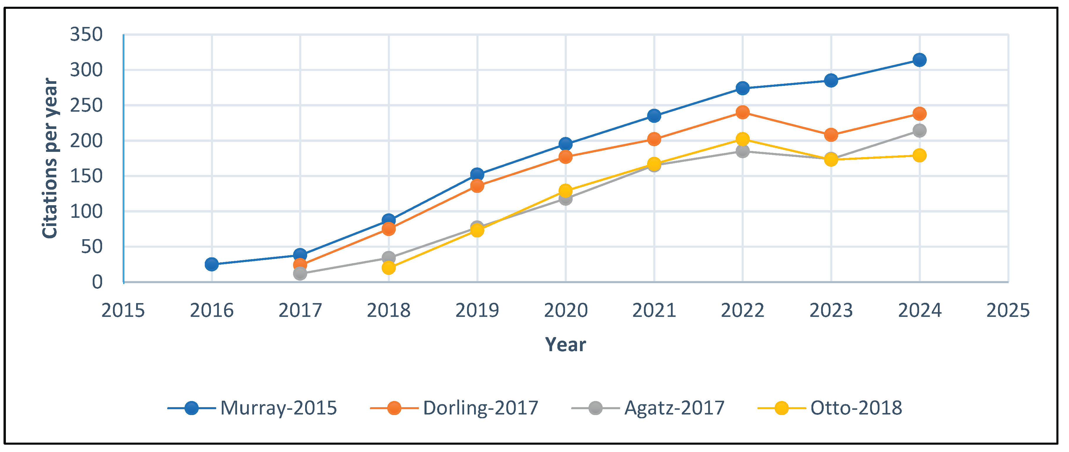
Figure 2.
Literature mapping for supply drone landing zone technology.
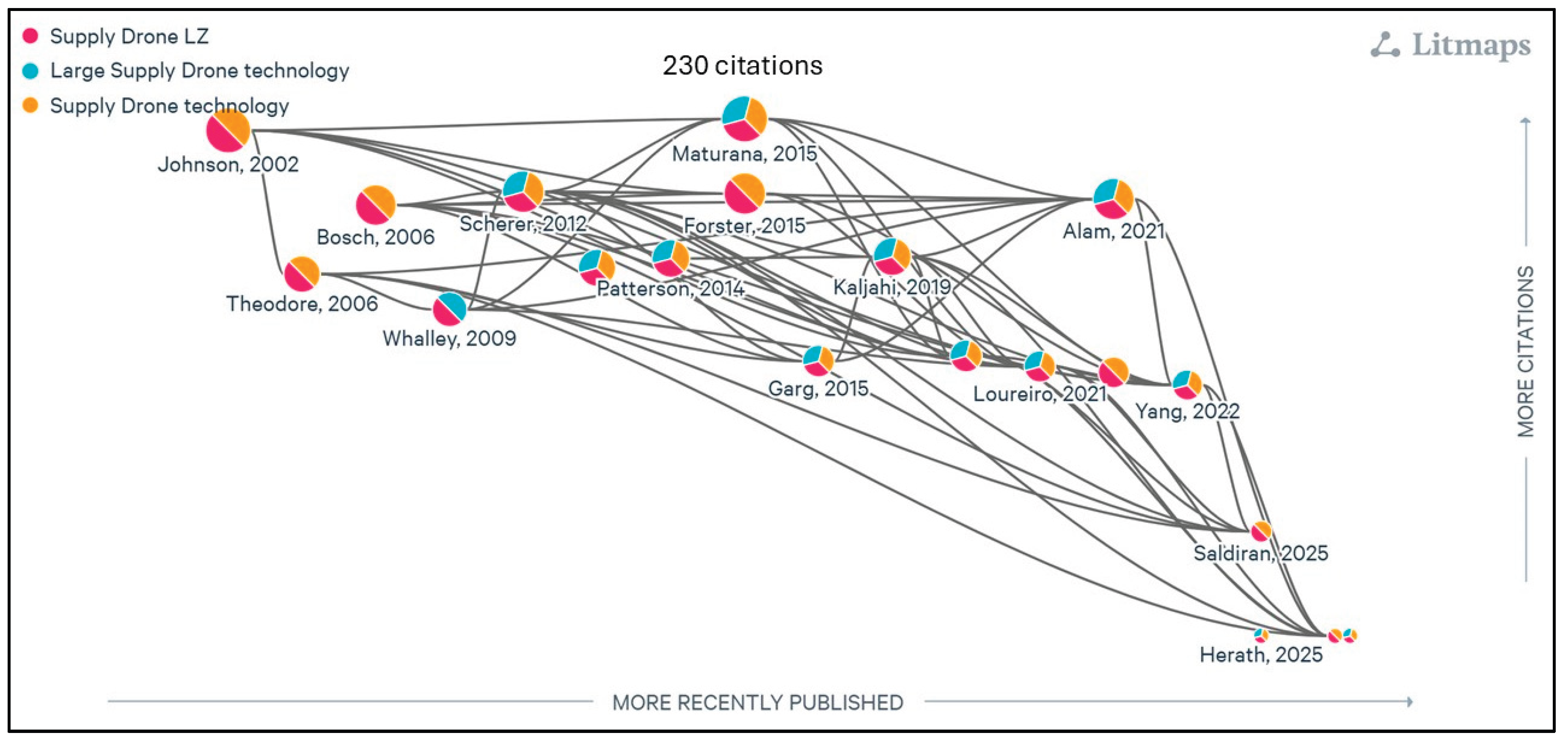
Figure 3.
Literature mapping of powerplant technology for supply drones.
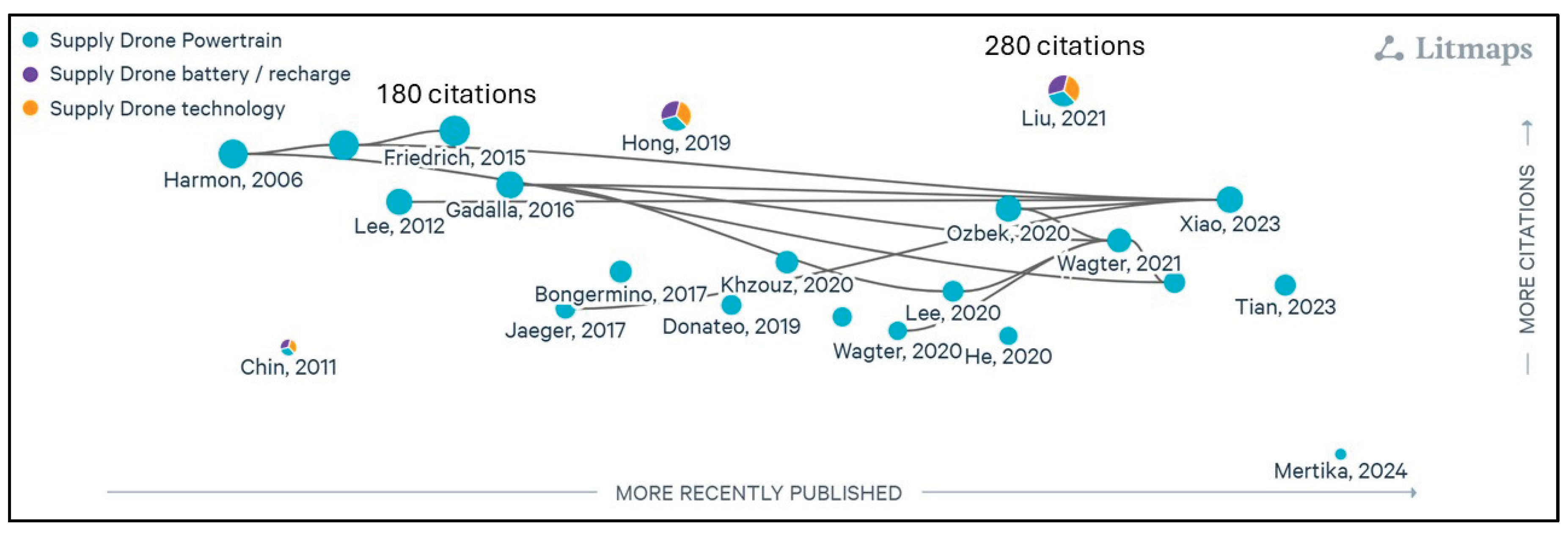
Figure 4.
Sketch of Concept One.
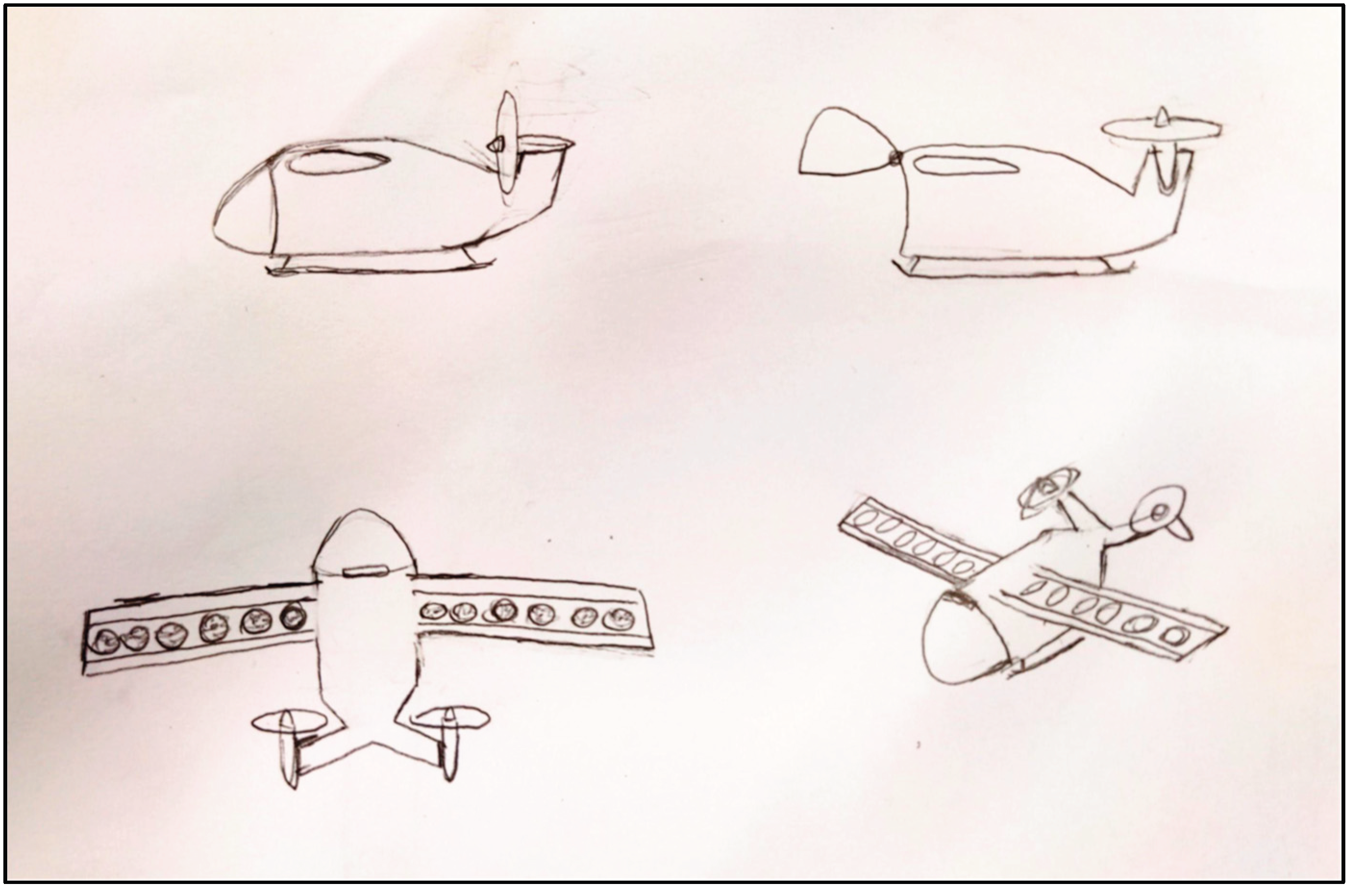
Figure 5.
Concept Two.
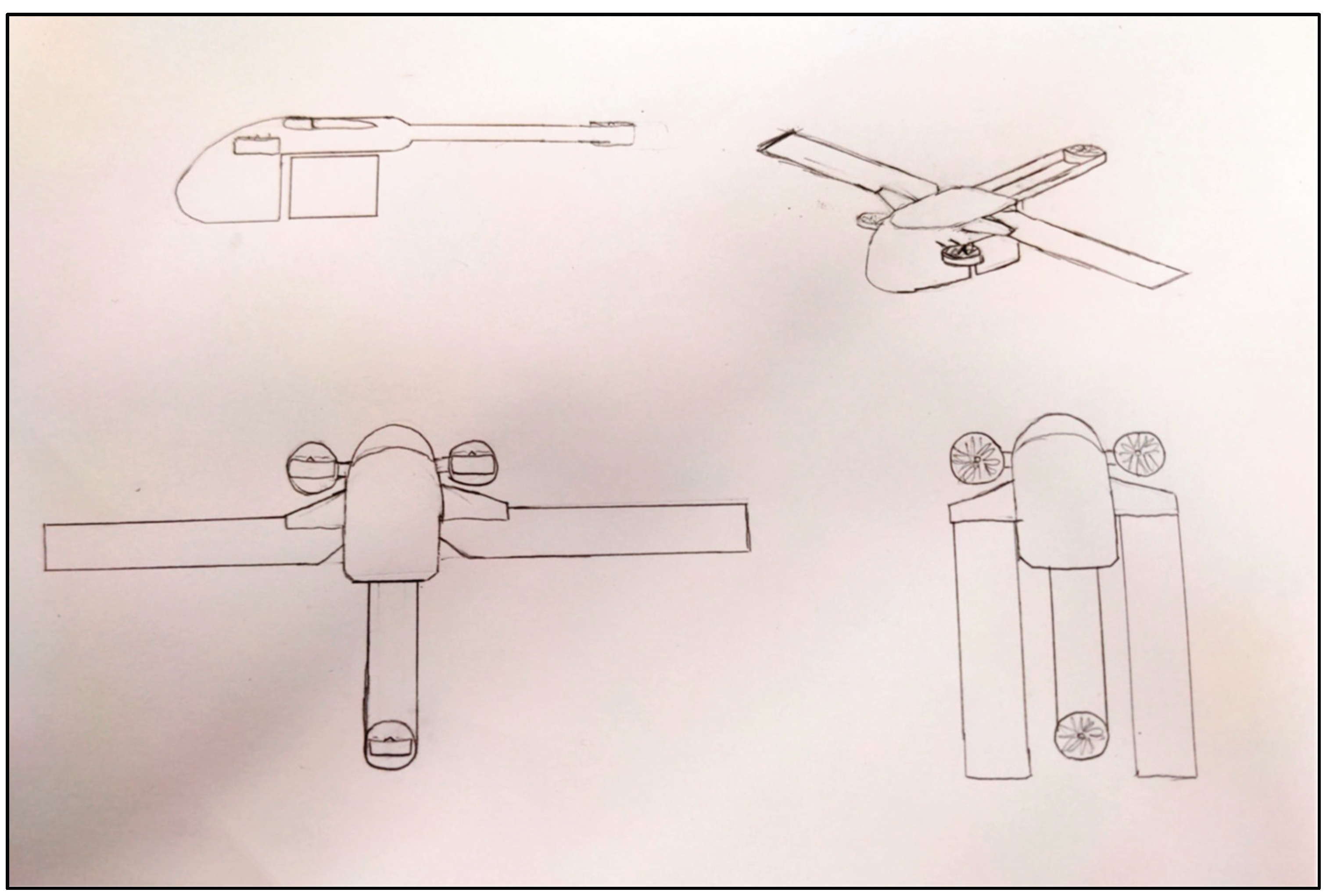
Figure 6.
Power and wing lift in transition.
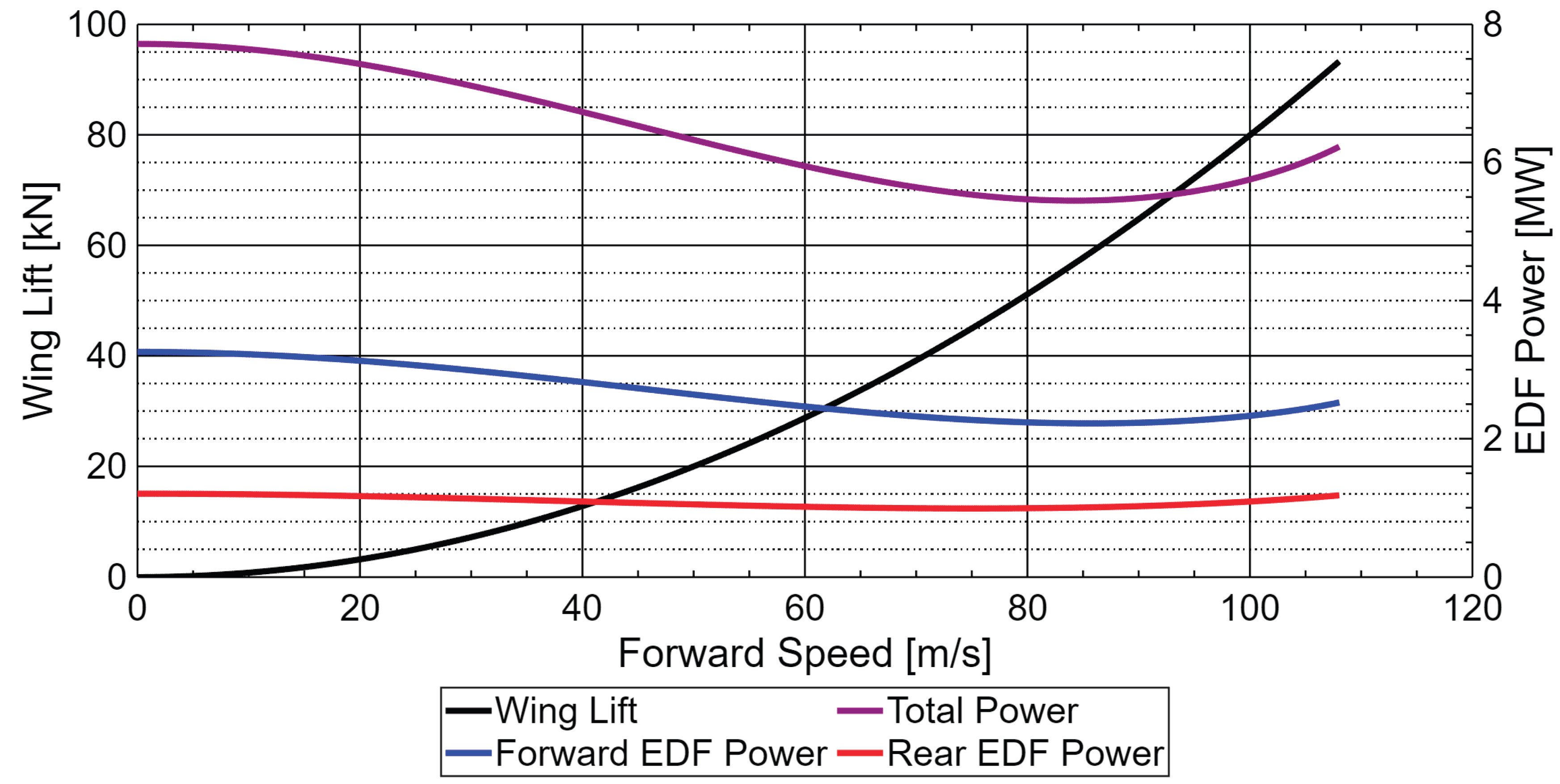
Figure 7.
Adaptive Ducted Fan thrusts in transition.
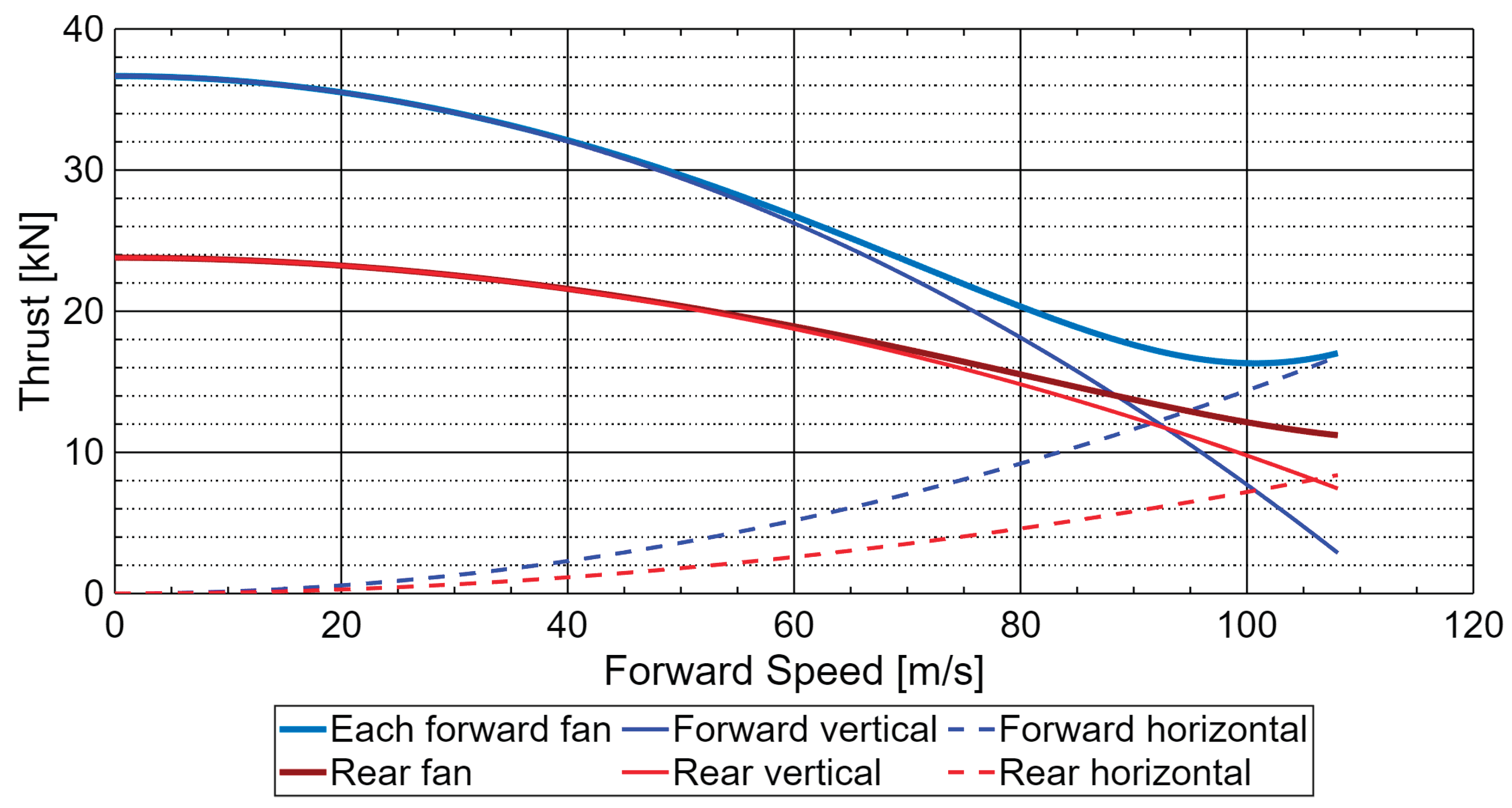
Figure 8.
Adaptive Ducted Fan tilt angles in transition.
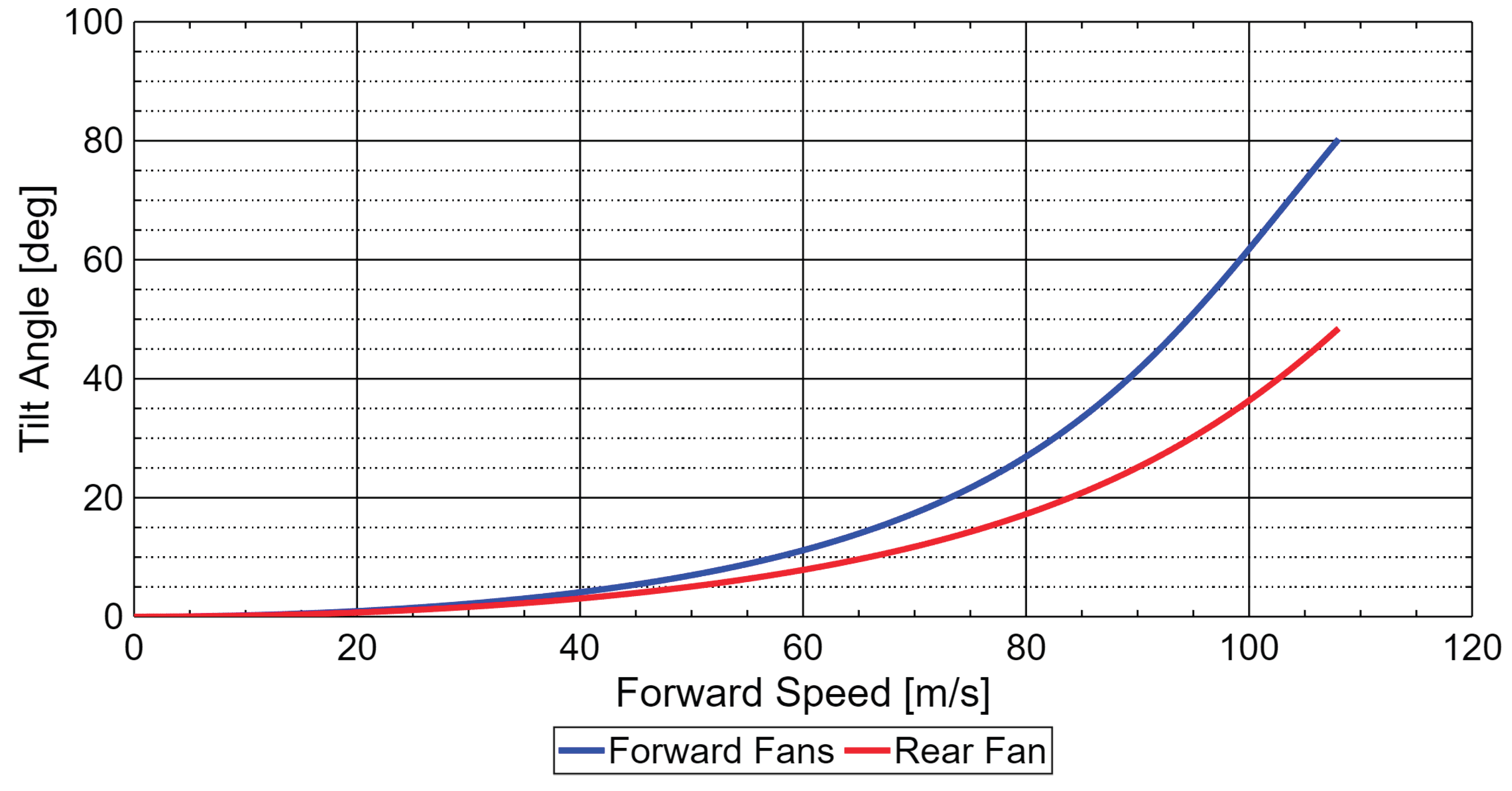
Figure 9.
Updated transition flight model (Note: L/D is 2 and CL is 0.682 below 60m/s).
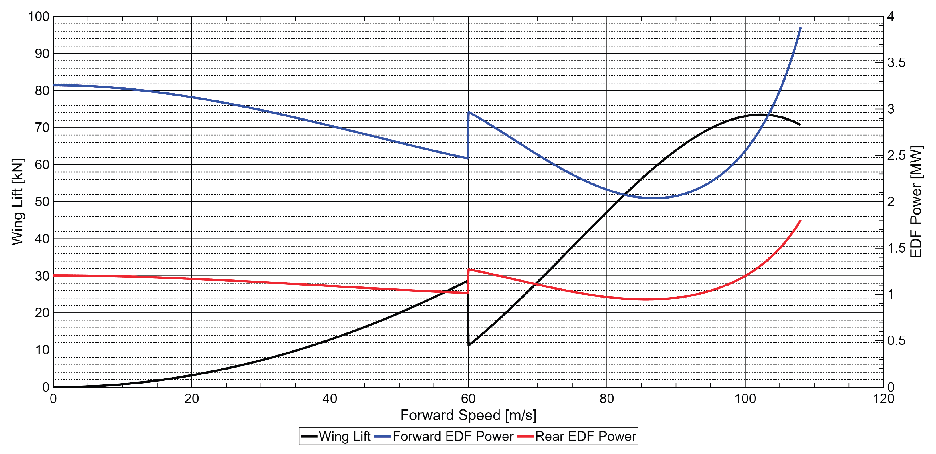
Figure 10.
CFD analysis of velocity magnitude pathlines at 80 m/s (upper) and 108 m/s (lower).
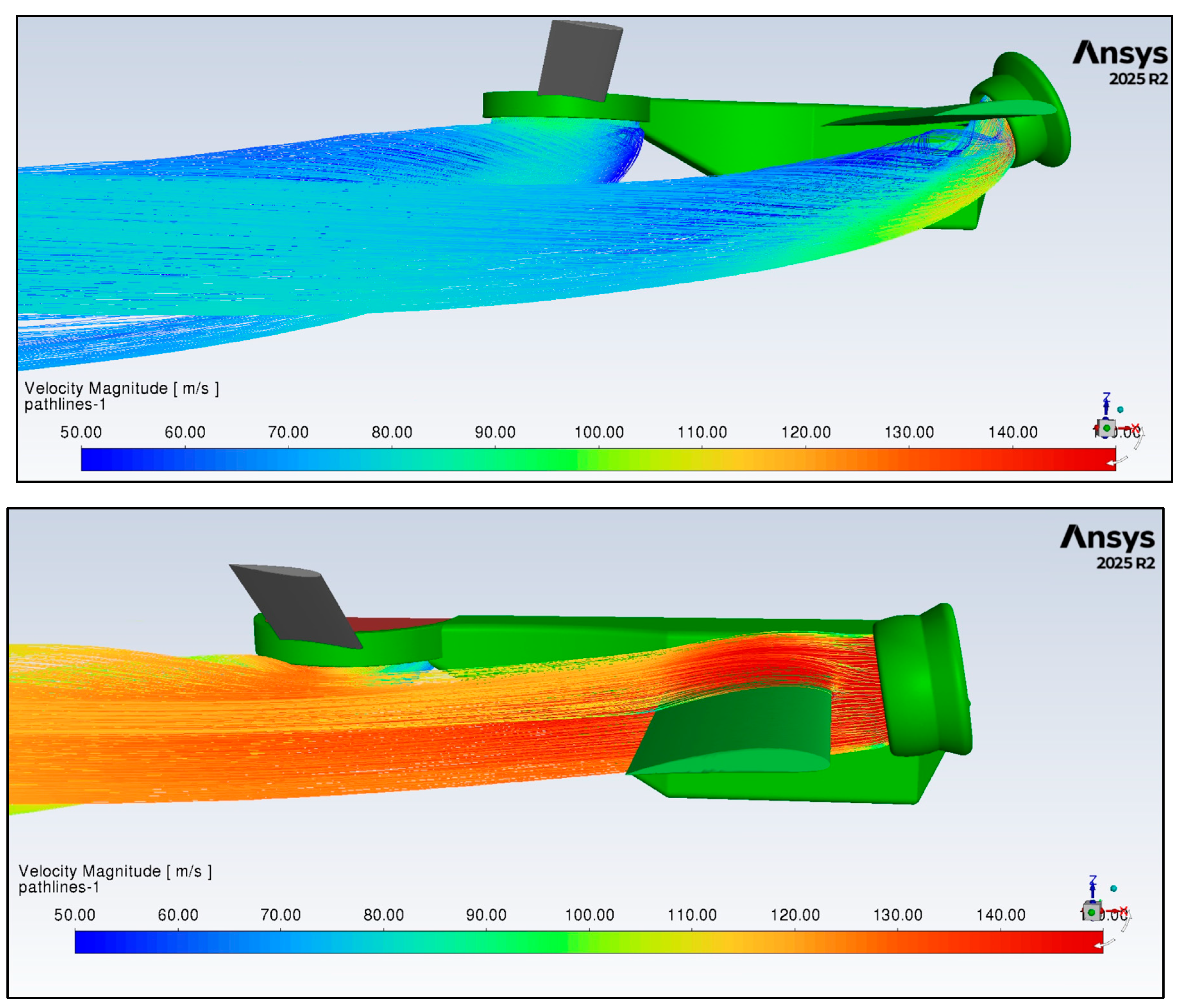
Figure 11.
The Dragonfly large supply drone concept.
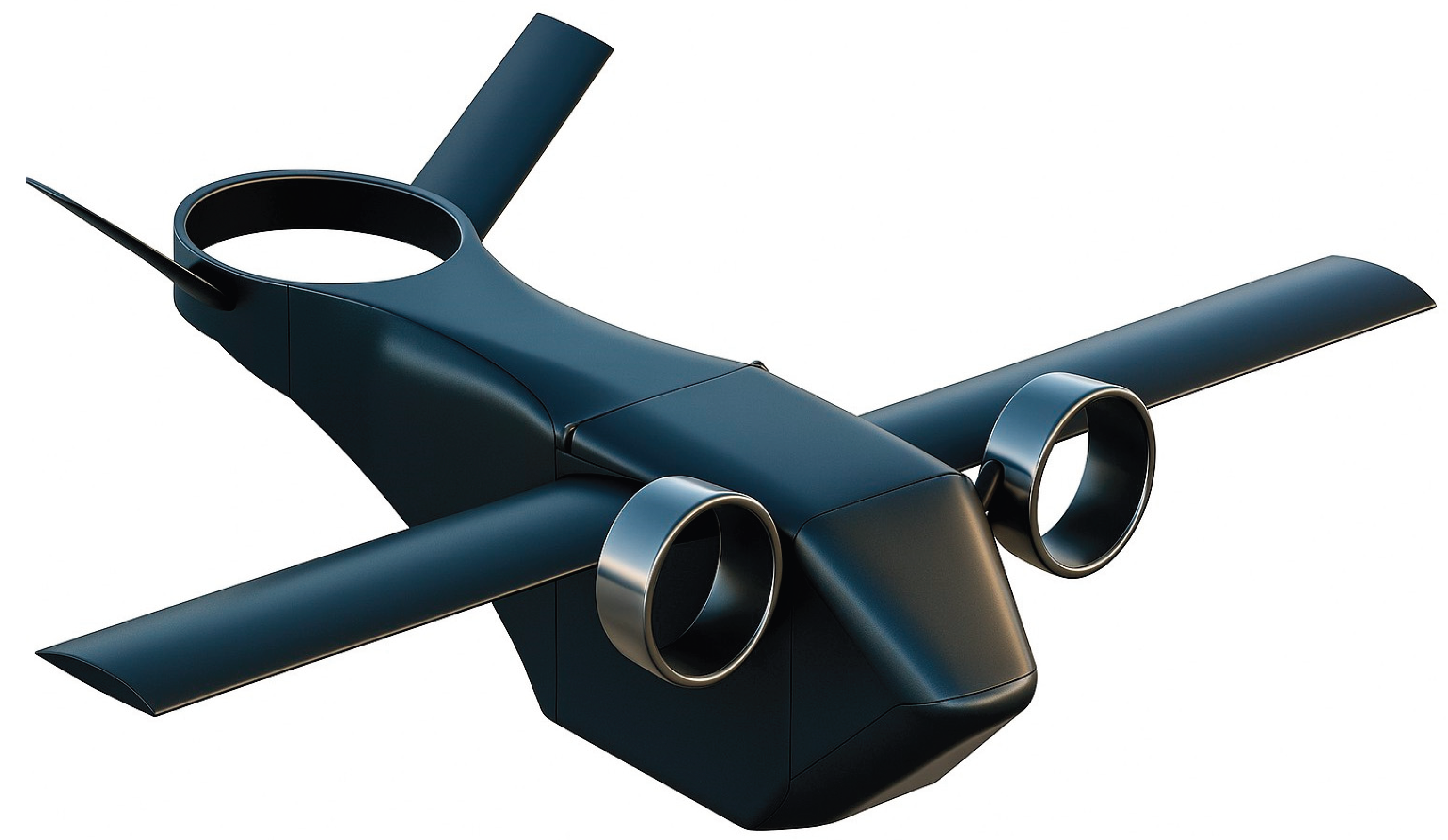

Table 1.
CFD validation cases for transition flight validation.
| Freestream velocity | Front ADF | Rear ADF | ||
|---|---|---|---|---|
| (m/s) | Angle (°)a | Exit Speed (m/s) | Angle (°)a | Exit Speed (m/s) |
| 60 | 78.52 | 100.00 | 81.89 | 66.30 |
| 80 | 62.75 | 133.33 | 72.75 | 88.42 |
| 108 (cruise) | 9.96 | 180.00 | 41.53 | 119.37 |
a All angles are taken from the horizontal plane.
Table 2.
Test plan for CFD Campaign.
| Run | Vertical Position-% of the front ADF diameter |
Spanwise position-% of the front ADF diameter |
L/D |
|---|---|---|---|
| 1 | -10 | 0 | 8.835 |
| 2 | -10 | 50 | 10.381 |
| 3 | -10 | 100 | 10.350 |
| 4 | 0 | 0 | 9.229 |
| 5 | 0 | 50 | 10.359 |
| 6 | 0 | 100 | 10.327 |
| 7 | 10 | 0 | 9.092 |
| 8 | 10 | 50 | 10.295 |
| 9 | 10 | 100 | 10.346 |
Table 3.
Key Dimensions and details of the Dragonfly large-scale supply drone.
| Component | Key Dimensions |
|---|---|
| Wing | 13.2 m span, 2.0 m chord, 26.4 m2 area, NACA 2412 airfoil, Wing set angle 4.3 degrees |
| Fuselage | 9.14 m length, 2.105 m width, 2.71 m height |
| V-tail | Each surface 2.11 m span, 1.21 m chord, dihedral angle of 36.9 degrees, NACA 0009 airfoil |
| Side Nacelles | 1.45 m diameter, 0.745 m length |
| Rear Shroud | 2.59 m diameter, 0.50 m length (blended) |
Disclaimer/Publisher’s Note: The statements, opinions and data contained in all publications are solely those of the individual author(s) and contributor(s) and not of MDPI and/or the editor(s). MDPI and/or the editor(s) disclaim responsibility for any injury to people or property resulting from any ideas, methods, instructions or products referred to in the content. |
© 2025 by the authors. Licensee MDPI, Basel, Switzerland. This article is an open access article distributed under the terms and conditions of the Creative Commons Attribution (CC BY) license.
Copyright: This open access article is published under a Creative Commons CC BY 4.0 license, which permit the free download, distribution, and reuse, provided that the author and preprint are cited in any reuse.


