
Submitted:
11 December 2025
Posted:
12 December 2025
You are already at the latest version
Abstract
The development of autonomous cargo ships necessitates reliable anchoring operations, a critical challenge due to low-speed maneuverability issues and anchorage disturbances. This paper addresses the challenges of reduced maneuverability at low speeds and susceptibility to anchorage disturbances in autonomous cargo ships, conducting research on anchoring decision-making methods. The process was systematically analyzed. Safety anchorage areas were quantified using ship parameters and environmental data. An available anchor position identification method based on grid theory, combined with an anchorage allocation mechanism to derive optimal anchorage selection. The development of a multi-level guided anchoring trajectory planning algorithm was informed by practical anchoring. This algorithm was designed to facilitate the scientific calculation of turning and stopping guidance points, with the objective of guiding cargo ship to navigate towards the anchorage in a predetermined attitude. An integrated autonomous anchoring system was constructed, encompassing perception, decision-making, planning, and control. Digital simulations verified the system's effectiveness and robustness under complex sea conditions. This study provides a theoretical foundation and feasible technical approach for enhancing the autonomous decision-making and safety control capabilities of intelligent ships during anchoring operations.
Keywords:
autonomous cargo ship
; anchoring
; decision-making method
; optimization
1. Introduction
Maritime transport, as the most environmentally friendly and cost-effective mode of global freight movement, underpins the steady development of the world economy. Statistics indicate that in 2024, it carried approximately 85% of global trade goods, with a total volume exceeding 12.5 billion tons[1]. Alongside this critical role, the maritime industry is undergoing a profound transformation characterised by the development of larger, more intelligent, and increasingly autonomous cargo ships[2,3,4]. Autonomous cargo ships are defined as vessels capable of operating independently with varying degrees of human oversight, primarily aimed at enhancing safety and preventing environmental pollution. A core objective for intelligent ships is to achieve full-path autonomous navigation, encompassing all operational phases: open-ocean voyages, coastal navigation, port entry and exit, berthing/unberthing, and anchoring[5].
Significant research efforts have been devoted to autonomous navigation in open and coastal waters, with substantial progress in areas such as collision avoidance, path optimisation, and trajectory control for berthing operations [6,7,8]. However, research focusing on the autonomous anchoring scenario remains relatively scarce. Anchoring is a critical and complex manoeuvre within a ship's navigation path, presenting unique challenges that are distinct from underway navigation. As a ship approaches an anchorage, its speed decreases sharply, leading to a rapid deterioration of manoeuvrability due to reduced rudder and propeller effectiveness[9]. This low-speed regime, compounded by constraints such as limited navigable water width, shallow water effects, and the presence of dynamic and static obstacles (including other anchored vessels), makes precise track-keeping and final positioning particularly arduous[10]. In conventional practice, decisions regarding anchor site selection and the anchoring manoeuvre rely heavily on the experience and judgment of seafarers. This reliance introduces risks associated with human error, which can lead to incidents such as improper anchor positioning, anchor dragging, anchor chain failure, and even collisions[11,12].
Therefore, developing automated anchoring systems is imperative to enhance safety and operational reliability. Such systems must comprehensively account for anchorage area characteristics, the fundamental constraints of ship manoeuvring at low speeds, and adhere to the International Regulations for Preventing Collisions at Sea (COLREGs) alongside the principles of good seamanship.
Research on autonomous ship anchoring intersects several key areas, including anchorage safety assessment, low-speed ship maneuvering, and intelligent navigation decision-making. [13] improve the teambuilding, leadership and communication through the anchor handling simulator. To describe anchoring procedures and typical human errors, [14] research the cause of many marine accidents related to the anchoring of vessels and their manoeuvring in anchorage areas. Along with the progressive development of port traffic, a novel anchorage collision risk model in the identification of the collision risk of anchorage is provided[15]. It may serve as a reference for the safety analysis of port traffic and assist maritime surveillance operators in the collision risk monitoring of port traffic to enhance traffic safety.
A core challenge for autonomous anchoring is the severe degradation of ship controllability at low speeds, which is critical during the final approach[16]. The anchoring operation itself is a structured process, typically described in phases such as approach, positioning, and anchor release[17]. Expert knowledge and hydrometeorological conditions are recognised as crucial factors in planning and executing these procedures[18]. This body of work highlights that successful anchoring is a complex manoeuvre requiring precise kinetic energy management and attitude control under environmental influences, not merely a path-following task.
Research on the Path Planning for Autonomous Navigation is increasing, such as the Artificial potential field[19], Line of light[20], Fast Marching Square algorithm[21] and so on. For complex, dynamic environments, recent research has focused on developing adaptive decision-making systems that comply with navigation rules (COLREGs) and account for motion uncertainty[22,23,24,25]. While these methods are effective for vessels underway in open or coastal waters, they are not directly designed to solve the terminal-phase problem of navigating to and securing a static point within a bounded, congested anchorage area.
A review of the literature reveals a distinct gap in developing integrated systems for autonomous anchoring. While component technologies—such as anchor holding models, low-speed dynamics, and general path planning—are well-studied, few works address the combined challenge of (a) dynamically selecting an optimal anchor position within a crowded anchorage in real-time, and (b) planning and executing a complete, robust trajectory from the approach phase to the anchor drop, specifically tailored to address low-speed controllability loss. This study aims to bridge this gap by proposing a cohesive system that links perception, optimised decision-making, and robust trajectory planning specifically for autonomous anchoring. To address these challenges, this paper focuses on the autonomous anchoring problem for large cargo ships. The study proposes an integrated decision-making and planning system encompassing three core components: (1) a quantitative method for dynamic safety anchorage area calculation based on ship parameters and environmental forces; (2) a grid-based algorithm for identifying available and optimal anchor positions that maximize the safety margin; and (3) a novel multi-level guided trajectory planning algorithm that generates a complete anchoring path through strategically determined turning, decelerating, and stopping guidance points. The proposed system is validated through digital simulations using a high-fidelity ship motion model under complex anchorage geometries and environmental conditions. This work aims to provide a theoretical foundation and a practical technical pathway for advancing the autonomous decision-making and safety control capabilities of intelligent ships during anchoring operations.
2. Ship Safety Anchoring Positioning
Anchoring operations are highly practical and involve complex processes, posing a significant challenge for autonomous execution. When a cargo ship enters an anchorage, its speed decreases sharply, causing a rapid decline in manoeuvrability [26]. To precisely reach the designated anchor position, frequent adjustments to the engine and rudder are required, which induce perturbations in the ship's hydrodynamic coefficients. As speed continues to decrease, the ship becomes increasingly susceptible to large drifting motions caused by wind and current disturbances, often leading to loss of rudder effectiveness. Therefore, achieving reliable autonomous anchoring necessitates an integrated approach that combines robust path planning with principles of practical seamanship, while explicitly accounting for environmental disturbances and precisely controlling the ship’s approach angle, speed, and final position.
The environment in which this operation occurs—the anchorage—is itself a structured and constrained area. Anchorages are designated for ship anchoring, emergency manoeuvring, and sheltering from storms. Their layout is determined by factors such as port scale, the types and density of arriving ships, and the local hydrographic environment. Consequently, when making anchoring decisions, a vessel must comprehensively consider the anchorage's spatial layout, water depth, and other environmental factors to determine feasible locations within the context of a dynamically calculated safety anchoring area.
In practice, anchorage management follows specific protocols that influence decision-making. Local maritime authorities typically define anchorage boundaries but often allow ships to anchor based on arrival order, following either designated or free anchoring principles[27]. Ships using fixed-point anchoring are assigned specific positions by the Ship Traffic Service centre. In contrast, those employing free anchoring rely on seafarer judgment to select the safest and most advantageous spot, considering factors such as water depth, available space, and manoeuvrability. A common heuristic is to choose the centre of the largest available safe water radius as the optimal anchorage. This research aims to formalize and automate this expert judgment, developing a systematic decision-making method that enhances safety and operational efficiency for autonomous cargo ships.
2.1. Calculation of the Ship’s Safety Anchorage Area
When a ship is anchored, the ship may swing under the influence of wind, current, and tide, centred on the anchor fluke’s position on the seabed[28]. Its position is constrained within a certain range R by the anchor chain, as illustrated in Figure 1(a), which is called the ship’s safety anchorage area. For a cargo ship employing a single anchor, determining the required anchor chain length—a prerequisite for ensuring anchoring safety—depends on multiple factors, including external environmental forces (wind and current), anchorage conditions (layout, water depth, seabed composition), and the ship’s loading condition. As illustrated in Figure 1(b), the bedded anchor chain S includes suspended length S1 and bed length of the ship's anchor chain S2, respectively[29].
To ensure holding security and prevent anchor dragging, a fundamental equilibrium condition must be satisfied: the total holding force provided by the anchor and chain must equal or exceed the resultant external forces (primarily from wind and current) acting on the anchored vessel[29]. Once set, the holding capacity of the anchor flukes remains relatively constant. Consequently, the deployed anchor chain length becomes the primary adjustable parameter for achieving this balance. An insufficient chain length reduces the effective holding capacity, while an excessive length may result in an excessively large swinging radius or increase the risk of anchor dragging. Thus, the appropriate determination of anchor chain length is critical and can be derived as follows.
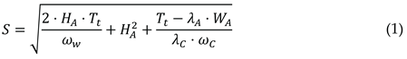
Where WA represents the weight of the anchor flukes, λA denotes the anchor holding power coefficient (ranging from 4 to 6, where it correlates with the anchor type). ωc signifies the weight per unit length of the anchor chain, λC indicates the holding power coefficient for the bedded anchor chain. And the resultant force Tt represents the total environmental disturbance—primarily from wind and current—acting on the anchored ship.

Where UC represents flow velocity, θC denotes the direction of flow velocity, ρw is the density of water. S is the ship's wet surface area, which can be calculated using Taylor's formula. cxa and cxa are the longitudinal surface friction coefficient and longitudinal form resistance coefficient of the hull. cyc is the transverse flow resistance coefficient acting on the ship. cprop and Ap are the propeller resistance coefficient and the propeller blade area, respectively.
To simplify calculations, this study references relevant research with practical anchoring experience, adopting the following formula for determining anchor chain release length[30], [31]:
Accordingly, the safe anchorage area is geometrically defined as a circular region centred on the projected anchor position, which satisfies the following condition:

Where (X0, Y0) represents the ship's position, and θa denotes the direction of the combined forces from wind, currents, and other environmental factors.
2.2. Available Anchor Position Determination Algorithm
When selecting an appropriate anchorage position within an anchorage area, a vessel must consider not only the local water depth but also the safe distance to other anchored ships. Therefore, identifying a feasible anchorage essentially involves integrating the predefined safe anchorage area to locate a position that meets all safety constraints within the limited available space. As illustrated in Figure 2, when the anchorage contains multiple target ships (TS1, TS2, …), the own ship (OS) must identify an available position that ensures safe clearance from all existing ships.
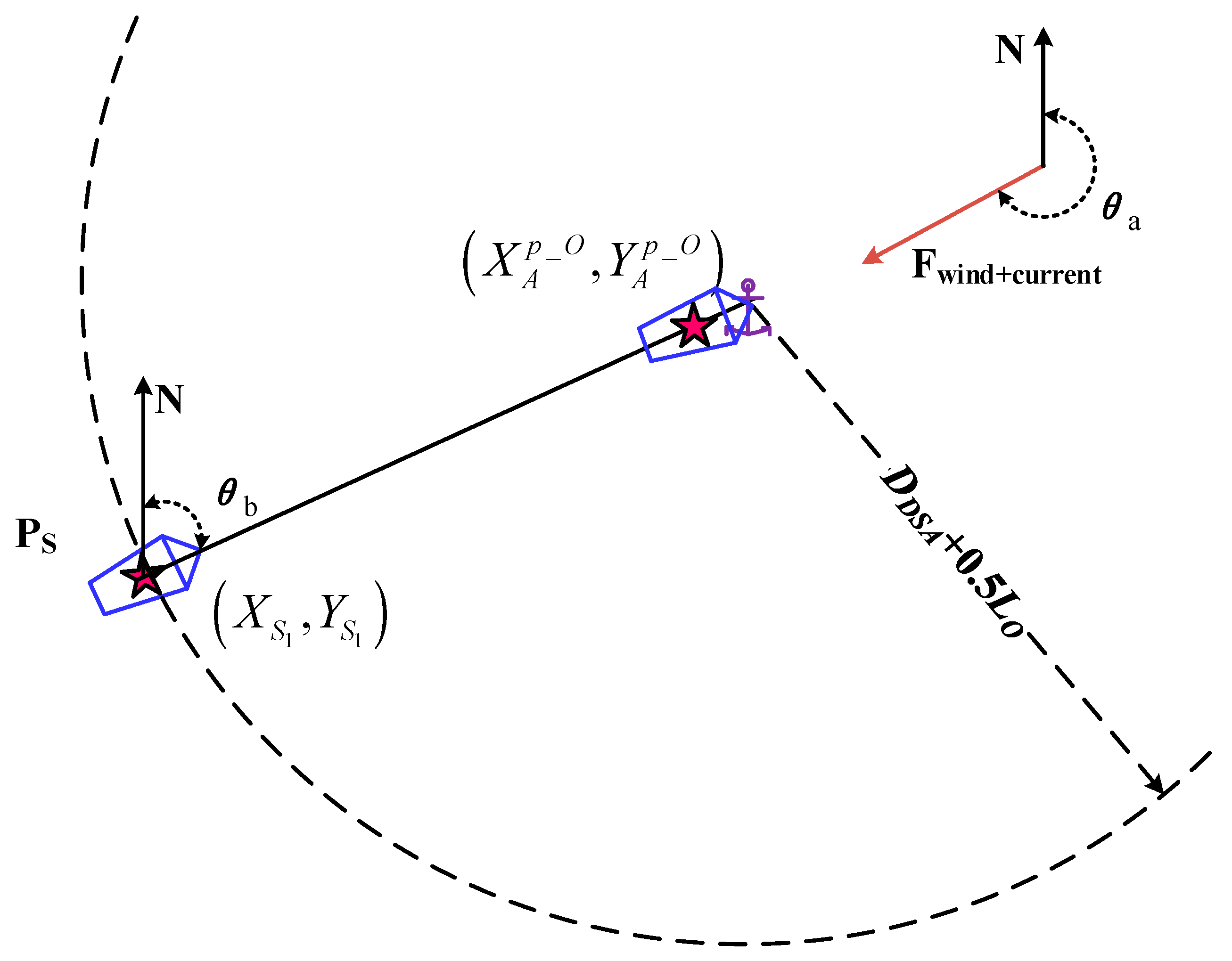
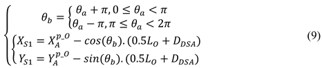
The position and length of the anchored ship in the fixed coordinate system (i=1,2…,m) is denoted by 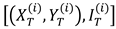 , which can be obtained through sensing equipment such as ECDIS, AIS, etc. This includes the positions, lengths, and headings of these ships. The positional data obtained from navigation sensors typically correspond to the geometric center of the ship. To determine the actual point where the anchor rests on the seabed—which is the true reference for the safety swinging radius—a geometric conversion is required. This conversion, which accounts for the ship’s length and heading, is given as follows.
, which can be obtained through sensing equipment such as ECDIS, AIS, etc. This includes the positions, lengths, and headings of these ships. The positional data obtained from navigation sensors typically correspond to the geometric center of the ship. To determine the actual point where the anchor rests on the seabed—which is the true reference for the safety swinging radius—a geometric conversion is required. This conversion, which accounts for the ship’s length and heading, is given as follows.
Where  means the coordinates of the anchored ship's anchor position. θb is the bow direction of the anchored ship, which can be shown as follows
means the coordinates of the anchored ship's anchor position. θb is the bow direction of the anchored ship, which can be shown as follows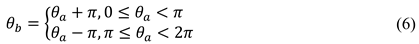
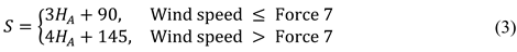
Following the aforementioned procedure, the safe waters for each target vessel can thus be determined, as visualised in Figure 4. Provided the wind force remains below Beaufort scale 7 during the operation, the corresponding safety radius for each vessel can be calculated using the formula 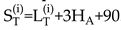 .
.
.Therefore, the feasible anchorage position is determined by the following formula.
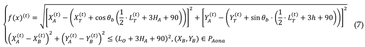
Where  denotes the shortest distance from the boundary of the preselected anchorage area to the target ship's anchorage area. (XB, YB) represents the ship's safe anchorage zone, while PAona indicates the anchorage area.
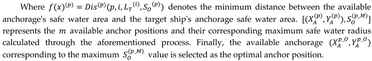
denotes the shortest distance from the boundary of the preselected anchorage area to the target ship's anchorage area. (XB, YB) represents the ship's safe anchorage zone, while PAona indicates the anchorage area. 2.3. Optima Anchor Position Determination Algorithm
While an available anchor position satisfies the basic safety requirements for anchoring, the optimal position must provide the maximum possible safety margin. In practice, under free anchoring rules, experienced mariners prioritise locations with the greatest clearance from other vessels and boundaries to minimise risks associated with anchor dragging or swing-circle overlap[32]. This principle is formalised here as selecting the anchorage with the largest attainable safety buffer.
Assume there are w available anchor positions within the anchorage, denoted as  ,where P = 1,2,...,w. For each candidate position, the associated safe anchorage radius is initially taken as
 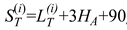 , consistent with the simplified model used in Section 2.2. Given the spatial interdependence of potential anchor positions, this study employs a grid-based approach to discretise candidate locations. Therefore, for each available anchor position, gradually increase the safe anchorage radius with that anchorage as the centre until the safe anchorage area conflicts with the already anchored area or exceeds the anchorage boundaries. This process determines the maximum safe anchorage range for each available anchor position. The complete computational procedure is illustrated in Figure 3.
,where P = 1,2,...,w. For each candidate position, the associated safe anchorage radius is initially taken as , consistent with the simplified model used in Section 2.2. Given the spatial interdependence of potential anchor positions, this study employs a grid-based approach to discretise candidate locations. Therefore, for each available anchor position, gradually increase the safe anchorage radius with that anchorage as the centre until the safe anchorage area conflicts with the already anchored area or exceeds the anchorage boundaries. This process determines the maximum safe anchorage range for each available anchor position. The complete computational procedure is illustrated in Figure 3.
3. Autonomous Anchoring Decision-Making and Planning System
Once the cargo ship has secured the optimal anchorage position, the urgent question for the intelligent cargo ship is how to confirm the completion of the anchoring task and plan the ship's anchoring trajectory under the constraints of the anchorage environment.
3.1. Ship Anchoring Procedure
Prior to arrival, a comprehensive anchoring plan is formulated, considering the ship’s principal dimensions (e.g., length overall, draft), anchor equipment configuration, and the hydrographic and environmental conditions of the anchorage. This plan includes selecting the appropriate anchoring method, which can be broadly classified as single-anchor or double-anchor operations depending on the intended manoeuvring approach and equipment setup[33]. In detail, double-anchor operations may be categorised by the direction of chain deployment into single-line, double-line, and parallel anchoring, while single-anchor operations are distinguished by water depth into deep-water and shallow-water anchoring—the latter further subdivided into forward-deployment and backwards-deployment methods[34].
This study focuses on large cargo ships, which predominantly employ the single-anchor backwards-deployment method in practice—that is, releasing the anchor while the vessel moves astern at low speed. The entire anchoring procedure can be systematically described in three consecutive stages[13], as illustrated in Figure 4:
(1)Approach stage
The ship transits from nearshore waters towards the anchorage area, adjusting its heading and speed to establish an initial state suitable for subsequent precise, low-speed maneuvering. A significant challenge during this phase is that large cargo ships are prone to considerable drift angles at low speeds due to environmental disturbances such as wind and currents, which can severely compromise their track-keeping ability. To counteract this and maintain steering effectiveness, it is a standard seamanship practice to align the ship's heading with the direction of the resultant environmental force (wind and current). This target heading can be determined through theoretical calculation or by observing the alignment of other vessels already at anchor.
(2)Positioning stage
The vessel proceeds toward the predetermined anchor position, accounting for wind and current influences while controlling speed based on stopping distance. Controlling speed is critical during anchoring operations. In practice, the captain manoeuvres the cargo ship to maintain the minimum speed required for rudder effectiveness while entering the anchorage. They then identify the optimal moment to stop, utilising the ship's momentum to drift to the designated anchorage position. The cargo ship cannot arrive at the anchorage using residual speed and must continuously employ kick-ahead manoeuvres to maintain forward motion if the ship stops too early. If the ship stops too late, the anchorage position will be reached with excessive speed. To reduce speed rapidly, prolonged high-gear reverse thrust is required. The bow will experience significant deflection due to the lateral force from reverse thrust, resulting in an anchoring attitude that fails to meet anchoring requirements.
In Figure 4, point OS3 represents the planned stopping position, determined by the ship's stopping distance. During the anchoring process, the ship's speed must be reduced to the minimum required to maintain steering effectiveness before reaching OS3.
(3) Dropping stage
Upon reaching the target position, the anchor is released with a predetermined length of chain, either manually or via a remote-controlled system, completing the anchoring operation[35]. When approaching an anchorage area, a cargo ship can detect anchorage positions and static or dynamic obstacles based on the traffic environment. Taking into consideration the ship's dimensions and the constraints of water depth and environmental forces, it determines whether a designated anchorage position can guarantee secure anchoring whilst accounting for the limitations imposed by water depth and environmental disturbances. The optimal anchorage position is selected from the feasible set[36]. Subsequently, the most suitable anchoring method is chosen based on the anchorage's hydrography and the available safe water area. Subsequently, the anchor is broken down as shown in Figure 5.
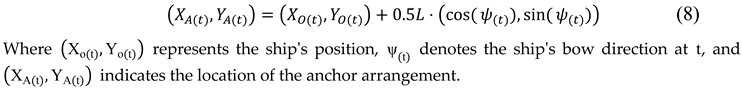
A critical geometric relationship underpins this final phase. The “anchor position (Position ① )” refers to the seabed location of the anchor fluke, which is practically represented by the position of the ship's bow at the moment of release. It is important to note that the ship's position (typically provided by GPS and approximating the geometric centre, Position ②) and the bow position are offset. This relationship is defined as:
3.2. Algorithm for Ship Anchoring Trajectory Planning Based on Multi-Level Guided
Building upon the anchoring procedure detailed in Section 3.1, this section presents a multi-level guided algorithm for ship anchoring trajectory planning. Large cargo ships operating at low speeds are particularly susceptible to significant drift angles induced by environmental disturbances, which severely compromise effective track-keeping capabilities[37]. To address this challenge, the proposed algorithm systematically integrates the three critical phases of the anchoring process—turning, stopping, and drifting—into a cohesive trajectory planning framework.
The algorithm is structured around three interconnected components: the ship stopping guidance point PS, ship decreasing guidance point PD, and the ship's altering guidance point PA. These components correspond to the three sequential phases of the anchoring procedure as shown in Figure 6: the approach phase corresponds to the the ship turning guidance point, the positioning phase corresponds to the segment from the ship stopping guidance point to the ship stopping guidance point, and finally, the anchoring phase corresponds to the segment from the ship stopping guidance point to the optimal anchor position. For intelligent cargo ships, the algorithm determines optimal turning and stopping points by accounting for environmental factors such as wind and current conditions. This integrated approach ensures that external forces do not adversely affect the ship's motion during each phase of the manoeuvre. By synthesising these three stages, the algorithm generates a complete, optimised anchoring trajectory that minimises drift, enhances safety, and maximises operational efficiency throughout the entire anchoring procedure.
3.2.1. Ship Stopping Guidance Point
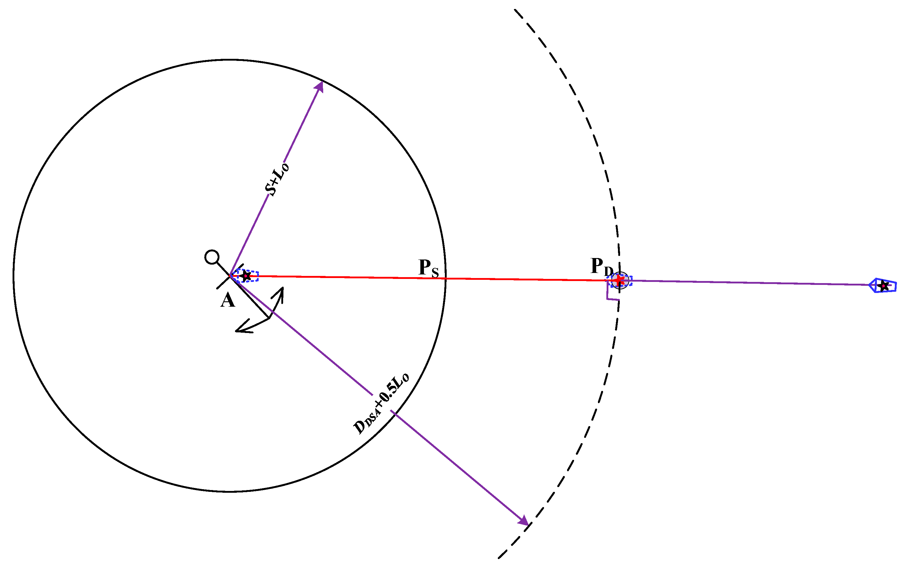
The ship stopping guidance point is defined as the position at which the cargo ship executes the stopping order subsequent to the completion of attitude adjustments. The determination of this parameter is contingent upon the anchor position and the ship's stopping distance[38].
Prior to operational deployment, the ship's stopping distance and turning circle parameters can be obtained through sea trials, under various engine commands. It is recommended that these data be plotted and subsequently displayed in a prominent location on the bridge, thus enabling the captain and pilot to access them intuitively. In actual anchoring operations, the stopping distance is selected based on environmental factors and the ship's main engine order. In order to facilitate the analysis, this study adopts the stopping distance DDSA as determined by the dead slow ahead for main engine command. The determination of the stopping guidance point PS is then made by considering the direction θa of the combined wind and current forces, as illustrated in Figure 6:
Figure 7.
Schematic diagram of ship stopping guidance point position.
The position (XS1, YS1) of the ship's stopping guidance point, determined by combining the optimal anchorage position with the direction of the combined wind and current forces, and the angle θb at which the ship is guided into the berth, is illustrated as follows:
3.2.2. Ship Decreasing Guidance Point
Within the practice of anchoring, the captain implements a strategy to mitigate the consequences of frequent engine usage, which can lead to main engine failure or wind-current interference at low speeds. This strategy involves the limitation of engine orders issued, thereby reducing the overall demand on the engine system. Ship's decreasing guidance point is to ensure that the ship can obtain a speed that meets the requirements for anchoring when at a designated anchor position. It is delineated as a point with its centre at the anchorage position and radius DDSA + 0.5LO.
Figure 8.
Schematic diagram of a ship with decreasing guidance point position.
3.2.3. Ship Altering Guidance Point
In the process of navigating towards a designated stopping guidance point at the minimum speed required to maintain steering effectiveness, a ship's trajectory is subject to disruption by various dynamic and static targets, navigational obstructions, and other elements present in the waterway. To ensure the cargo arrives at the stopping guidance point in the designated attitude, the anchorage turning guidance point must be determined by considering the altering circle parameters in conjunction with its current position, heading, and other factors.
The altering guide points are indicated as shown in Figure 9. Firstly, the optimal anchorage position A and the ship's stopping guide point S are combined. The intersection point D of the two courses is then calculated based on the ship's current position O and heading Cθ. This results in the location (XD, YD) being determined. It can be concluded that this ensures that the ship can complete the anchoring operations along the designated trajectory 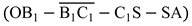 or
or  within the limits of its manoeuvrability. In this context, (B1 or B2) denotes the turning guidance point at different main engine commands for the cargo ship.
or within the limits of its manoeuvrability. In this context, (B1 or B2) denotes the turning guidance point at different main engine commands for the cargo ship.The formula for calculating the altering radius RV is as follows, where Vs and Vt represent the ship's speed before turning and during steady turning, respectively.
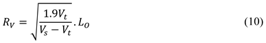
Considering that ships heading to anchorage positions may encounter external disturbances such as wind and currents, this study adopts the turning circle formed during the ship's dead slow ahead manoeuvre as the altering guide circle to ensure sufficient straight-running time for speed recovery after altering. The turning guide point B is located within the anchorage turning zone, and its position (XB, YB) is calculated as follows:
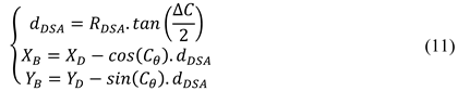
Where dDSA represents the distance from point D to the steering reference point B. ΔC for the turning angle, and RDSA indicates the radius of steady turning for the simulated ship under the dead slow ahead command, which can be obtained from the ship's turning performance parameter chart.
3.3. Decision-Making Method for Cargo Ship Safe Anchoring
When an autonomous cargo ship approaches the designated anchorage area, the required safety area for anchoring is initially calculated based on the ship's displacement, draft, anchor equipment parameters, and water depth. Subsequently, the occupied anchorage areas of vessels already at anchor are determined by considering their dimensions, headings, and positions within the anchorage. Following this, the optimal anchorage position is identified using the available anchor position determination program and the optimal anchorage position determination program, as introduced in Section 3.1.
Simultaneously, based on the determined optimal anchorage position and local hydrometeorological conditions, a suitable automatic anchoring method is selected for the ship. Subsequently, in accordance with the ship's current position and target vessel information, and in combination with the optimal anchorage position and anchoring method, a multi-level guided anchoring planning trajectory is constructed under the constraints of the ship's manoeuvrability and the approach angle for anchoring. Finally, through the course and speed control system, the anchoring task is completed with the assistance of a remote anchoring system. The complete decision-making procedure for safe ship anchoring is illustrated in Figure 10.
4. Case Study
4.1. Setup
To systematically validate the effectiveness and robustness of the proposed anchoring decision-making system, a comprehensive simulation case study was conducted. The experimental setup encompasses four key components: (1) the selection of representative anchorage areas, (2) the configuration of realistic maritime traffic scenarios, (3) the specification of the test ship's particulars, and (4) the definition of precise evaluation criteria for anchoring performance. High-fidelity real-world data was integrated to construct a challenging and credible simulation environment.
(1) study area
To comprehensively validate the proposed anchoring decision-making system, two representative anchorage areas in the East China Sea were selected for the case study: the east side of Liuheng Island (as shown in Figure 11(a)) and the Xiazhimen Anchorage (as shown in Figure 11(b)). These sites were chosen due to their frequent use by large cargo ships, complex hydrodynamic conditions, and typical U-shaped geography, which collectively present a realistic and challenging scenario for testing autonomous anchoring algorithms. The precise geographical boundaries, as defined by the local maritime authority, are detailed in Table 1. These coordinates were imported into the simulation platform to construct a high-fidelity digital environment.
(2) Target ship information
To simulate a realistic and congested anchoring scenario, real AIS data from November 11, 2025, was utilised. Ten ships were present in the combined anchorages, with their static and dynamic parameters summarised in Table 2. The positions and headings of these ships were critical for calculating the safety areas and identifying available anchoring positions using the proposed grid-based algorithm.
(3) Ship particular
The test ship was a 76,000 DWT bulk carrier, "HUA XINGHAI," a typical Panamax-class ship belonging to the COSCO group. Its principal particulars, essential for modelling its manoeuvrability and calculating its safety anchorage radius, are listed in Table 3. The simulation environment was built using a combination of MATLAB/Simulink and a ship manoeuvring model based on the MMG (Manoeuvring Modelling Group) architecture, incorporating wind and fluid forces according to formulas derived from relevant literature[29,30,31,32,33].
(4)Evaluation Criteria for Anchoring Path and Final State
Once the optimal anchorage position is determined, the anchoring trajectory is planned based on the ship's manoeuvrability and current state (position, heading, speed). For large cargo ships performing a single-anchor operation, the success of the manoeuvre is typically assessed by several key factors: crew preparedness, positional accuracy of the anchor drop, the ship's heading and speed at the moment of anchoring, and the control of chain release.
Based on standard anchoring practice, the task is considered successful if the following conditions are met at the moment the anchor is released: 1) The difference between the ship's bow direction and the opposing direction of the combined environmental forces is within π/12; 2) The distance between the actual anchor position and the target optimal position is less than twice the ship's beam; 3) The ship's speed is less than 1.0 knot. These criteria are formalised as follows.
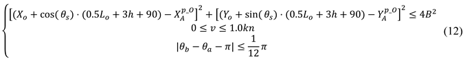
Where (XO, YO) represents the position of the ship at the time of anchoring, v indicates the speed of the ship, and B represents the beam of the ship.
4.2. Results and Analysis of Optimal Anchor Positioning
To systematically validate the effectiveness and robustness of the optimal anchor positioning algorithm proposed in Section 2.3, simulation experiments were conducted in two typical anchorage areas in the East China Sea: the east side of Liuheng Island and the Xiazhimen Anchorage. The environmental force (combined wind and current) direction was set to 270° (due west), simulating a common cross-current scenario. Based on the anchorage boundaries and the positions and lengths of anchored ships, the algorithm calculated the optimal anchor positions using a grid-based discretisation and a stepwise safe-water-area expansion strategy.
Figure 12 presents the distribution of optimal anchor positions output by the algorithm and the corresponding heat maps of safe water areas. The green markers indicate the computed optimal anchor positions, while the colour gradient in the heat maps reflects the maximum achievable safe radius at each location (darker colours indicate a larger safety margin).
For the east side of Liuheng Island anchorage, the optimal anchor position was determined at 122.293586°E, 29.622519°N(as shown in Figure 12(a) and 12(b)). This location is not the geometric centre of the anchorage but lies in the relatively open waters to the northeast, effectively avoiding the densely anchored ships to the North and west (TS1-TS5) while maintaining sufficient distance from the anchorage boundaries. For the Xiazhimen Anchorage, the optimal position was found at 122.356893°E, 29.696410°N(as shown in Figure 12(c) and 12(d)). This position is located in the south-central part of the anchorage, successfully fitting into a gap among the existing ships (TS6-TS10) and maximising the safe distance within the limited available space.
4.3. Validation of the Anchoring Trajectory Planning Algorithm
Following the determination of the optimal anchor position, the multi-level guided (turning, decelerating, stopping) trajectory planning algorithm proposed in Section 3.2 was employed to generate a complete navigation trajectory from the initial position to the anchor position. To evaluate the algorithm's adaptability to different environmental conditions, two distinct environmental force directions (270° and 330°) were set for comparative validation. Figure 13 presents the planned trajectories (red dashed lines) and the actual trajectories (blue solid lines) obtained from simulation using a high-fidelity MMG ship manoeuvring model under both scenarios. In the 270° environmental force scenario (Figure 13a), the ship's initial heading required significant adjustment to align with the opposite direction of the resultant environmental force. The algorithm generated a smooth trajectory, initiating the turn near the altering guidance point, beginning deceleration in the region of the deceleration guidance point, and finally arriving accurately at the stopping guidance point. The actual trajectory closely matched the planned one, with only minor deviations observed during the low-speed final approach due to changes in hydrodynamic characteristics and environmental disturbances.
In the 330° environmental force scenario (Figure 13b), the environmental force direction was closer to the initial heading, requiring a smaller turning magnitude. The algorithm accordingly generated a different turning point and trajectory shape, yet still successfully guided the ship to the anchor position with the desired attitude and speed. This confirms the algorithm's capability to dynamically adjust its planning strategy based on real-time environmental information.
5. Discussions and Analysis
This study developed and validated an integrated autonomous anchoring decision-making system through simulations in two realistic anchorage scenarios. The system performance can be discussed from three interconnected aspects: the effectiveness of the optimal positioning algorithm, the robustness of the multi-level trajectory planning, and the synergistic benefits of their integration within a complete autonomy framework.
(1) Performance of the Optimal Anchor Positioning Algorithm
The algorithm can comprehensively consider static obstacles (anchorage boundaries) and dynamic obstacles (other ships' safe water areas) to identify the globally optimal anchoring point within complex and crowded anchorage environments, rather than simply selecting the geometric centre or the nearest vacant spot. The proposed grid-based algorithm successfully identified anchor positions that maximised the safety buffer in congested anchorages (Figure 12). Its core strength lies in formalising the expert heuristic of selecting the "centre of the largest available safe water radius." As evidenced in Section 4.2, the algorithm did not default to geometric centres but found positions that optimally balanced distances from other ships and anchorage boundaries. The generation of a safety margin heat map is a valuable visual output, transparently illustrating the quantitative safety landscape of the anchorage to support decision-making.
In the scenario involving 10 target ships, the algorithm's computation time on a standard workstation was less than 5 seconds, meeting the requirements for real-time decision-making. Its grid-based approach facilitates integration with Electronic Chart Display and Information System (ECDIS) data, demonstrating strong potential for engineering applications. The computational efficiency confirms its feasibility for real-time operational use. This algorithm overcomes the potential for local optima and subjective bias inherent in traditional anchor position selection based on crew experience, providing autonomous ships with an objective, quantifiable, and safe decision-support method for anchor positioning.
(2)Robustness of the Multi-level Guided Trajectory Planning
The trajectory planning algorithm demonstrated robust performance under two distinct environmental conditions (270° and 330°), as shown in Figure 13 and Figure 14. By decomposing the complex manoeuvre into sequential phases governed by turning, decelerating, and stopping guidance points, the method effectively managed the key challenge of low-speed controllability loss. The close alignment between the planned and actual simulated trajectories, especially during the critical final approach, validates the guidance point calculation logic and its integration with the ship's manoeuvring model. The speed profile in Figure 14 clearly shows the algorithm's capability to execute necessary "kick-ahead" manoeuvres to maintain steerage, culminating in a final speed below 1.0 knot. The final state parameters (position error of 35-42 m, heading error within 15°, speed <1 kn) all met the strict success criteria derived from seamanship practices. This indicates that the algorithm does not merely generate a geometrically feasible path but plans a dynamic manoeuvre that accounts for kinetic energy management and environmental forces.
(3)System Integration and Practical Implications
The principal contribution of this work is the seamless integration of position optimisation and trajectory planning into a cohesive decision-making system (Figure 10 schematic). The optimal anchor position provides a target that inherently considers static and dynamic constraints, while the multi-level guided trajectory provides a safe and executable method to reach it. This end-to-end automation addresses the stated gap in research for autonomous anchoring scenarios. From a practical standpoint, the system offers a structured and replicable alternative to reliance solely on officer experience, potentially reducing human-error-related incidents like poor site selection or dragging anchors. The methods are built upon standard ship parameters and COLREGs-compliant logic, facilitating their adoption on existing vessels undergoing automation upgrades. The simulation-based validation using a high-fidelity MMG model under realistic anchorage geometries and traffic conditions strongly supports its engineering applicability.
6. Conclusions
This study developed an integrated autonomous anchoring decision-making system for cargo ships, addressing the critical challenge of reliable low-speed anchoring operations within constrained and dynamic anchorage environments. The system combines an optimal anchor positioning algorithm with a multi-level guided trajectory planning method, validated through high-fidelity simulations in realistic anchorage scenarios. The grid-based positioning algorithm successfully formalists expert seamanship heuristics, identifying anchor locations that maximize the safety buffer relative to other vessels and anchorage boundaries. The trajectory planning algorithm, structured around turning, decelerating, and stopping guidance points, demonstrated robust performance by generating executable paths that effectively managed speed loss and environmental drift, ensuring the ship reached the target position with a compliant attitude and minimal speed. The final state in all simulated cases met stringent criteria derived from practical anchoring standards, confirming the system's effectiveness and engineering applicability.
The primary contributions of this work are threefold: (1) providing a systematic, quantifiable framework for anchor position selection that enhances situational awareness and safety over experiential judgment; (2) proposing a novel phased trajectory planning approach that explicitly addresses the low-speed maneuverability degradation of large vessels; and (3) integrating perception, decision, planning, and control into a cohesive autonomous anchoring pipeline, offering a validated technical pathway towards full-path ship autonomy.
However, this research has certain limitations that point to future directions. The current model assumes constant environmental forces and simplifies the dynamic swinging behaviour of other anchored ships. Furthermore, the system's performance in extremely high-density anchorages or under emergency conditions warrants further investigation. Future work will focus on integrating time-varying environmental models, incorporating more sophisticated dynamic models for surrounding vessels, and extending the decision-making logic to cover a wider range of anchoring methods (e.g., double-anchor operations). Ultimately, validation through full-scale trials or high-fidelity digital twin simulations will be essential for transitioning this system from a theoretical framework to a deployed maritime technology.
Author Contributions
Conceptualization, W.Z. and B.W.; methodology, J.M. and B.W; software, X.Z.; validation, Y.H., G.L. and B.W.; formal analysis, W.Z. and B.W.; investigation, Y.H.; resources, W.Z.; data curation, B.W.; writing—original draft preparation, W.Z.; writing—review and editing, B.W.; visualization, X.Z.; supervision, J.M and Y.H.; project administration, B.W.; funding acquisition, J.M. All authors have read and agreed to the published version of the manuscript.
Funding
Please add: This research was funded by the National Natural Science Foundation of China, grant numbers 52271367, and the National Key R&D Program of China, grant number 2023YFB2603805.
Institutional Review Board Statement
Not applicable.
Informed Consent Statement
Not applicable.
Data Availability Statement
The original contributions presented in this study are included in the article. Further inquiries can be directed to the corresponding author.
Conflicts of Interest
The authors declare no conflicts of interest.
References
- Zhang, K.; Huang, L.W.; He, Y.X.; Wang, B.; Chen, J.H.; Tian, Y.F.; Zhao, X.Y. A real-time multi-ship collision avoidance decision-making system for autonomous ships considering ship motion uncertainty. Ocean Eng 2023, 278, 114205. [Google Scholar] [CrossRef]
- Wang, Z.Y.; Yang, P.; Gao, D.J.; Bao, C.T. Path-planning algorithm based on elastic force contractions for autonomous navigation of unmanned container ships in waterborne transportation. Ocean Eng 2024, 310, 118646. [Google Scholar] [CrossRef]
- Ohn, S.W.; Namgung, H. Requirements for Optimal Local Route Planning of Autonomous Ships. J. Mar. Sci. Eng 2023, 11, 11010017. [Google Scholar] [CrossRef]
- De Vos, J.; Hekkenberg, R.G.; Banda, O.A.V. The Impact of Autonomous Ships on Safety at Sea - A Statistical Analysis. Reliab Eng Syst Saf 2021, 210, 107558. [Google Scholar] [CrossRef]
- Li, M.; Zhao, X.; Jiao, Y.; Liu., C; Chu., X; Mou, J. Research on the risk of submarine cable damage from anchored ships based on probability analysis. Reliab Eng Syst Saf 2025, 261, 111114. [Google Scholar] [CrossRef]
- Cai, J.L.; Chen, G.Q.; Yin, J.; Ding, C.; Suo, Y.F.; Chen, J.H. A Review of Autonomous Berthing Technology for Ships. J. Mar. Sci. Eng 2024, 12, 120711377. [Google Scholar] [CrossRef]
- Zhao, X.Y.; Huang, L.W.; Zhang, K.; Mou, J.M.; Yu, D.Q.; He, Y.X. Dynamic Adaptive Decision-Making Method for Autonomous Navigation of Ships in Coastal Waters. IEEE Trans. Intell. Transp. Syst 2024, 25, 17917–17930. [Google Scholar] [CrossRef]
- Huang, Y.M.; Chen, L.Y.; Chen, P.F.; Negenborn, R.R.; Van Gelder, P.H.A.J.M. Ship collision avoidance methods: State-of-the-art. Saf. Sci 2021, 121, 451–473. [Google Scholar] [CrossRef]
- Kim, D.; Tezdogan, T.; Incecik, A. Hydrodynamic analysis of ship manoeuvrability in shallow water using high-fidelity URANS computations. Appl. Ocean Res 2022, 123, 103176. [Google Scholar] [CrossRef]
- He, Y.X.; Liu, X.; Zhang, K.; Mou, J.M.; Liang; Zhao, Y.; Wang, X.Y.; Huang, L.W. Dynamic adaptive intelligent navigation decision making method for multi-object situation in open wate. Ocean Eng 2022, 253, 111238. [Google Scholar] [CrossRef]
- Liu, Z.H.; Zhou, D.; Zheng, Z.Y.; Wu, Z.L.; Gan, L.H. An Analytic Model for Identifying Real-Time Anchorage Collision Risk Based on AIS Data. J. Mar. Sci. Eng 2023, 11, 11081553. [Google Scholar] [CrossRef]
- Woo, J.; Kim, D.; Na, W.B. Safety analysis of rock berms that protect submarine power cables in the event of an anchor collision. Ocean Eng 2015, 107, 204–211. [Google Scholar] [CrossRef]
- Havold, J. I.; Nistad, S.; Skiri, A.; Odegard, A. The human factor and simulator training for offshore anchor handling operators. Saf. Sci 2015, 75, 136–145. [Google Scholar] [CrossRef]
- Rutkowski, G. Analysis of human errors related to many marine accidents occurring while anchoring and manoeuvring at an anchorage. Sci. J. Gdyn. Marit. Univ 2019, 112, 45–59. [Google Scholar] [CrossRef]
- Liu, Z.; Wu, Z.; Zheng, Z. A novel model for identifying the vessel collision risk of anchorage. Appl. Ocean Res 2020, 98, 102130. [Google Scholar] [CrossRef]
- Li, M.X.; Mou, J.M.; Chen, L.Y.; Huang, Y.M.; Chen, P.F. Comparison between the collision avoidance decision-making in theoretical research and navigation practices. Ocean Eng 2021, 228, 108881. [Google Scholar] [CrossRef]
- Liu, X.; Deng, H.; Wang, B.; Zhang, K.; Wu, Y.; Zhao, X.Y. Research on the Method of Mooring Position Selection for Ships Riding to Single Anchor Based on Nautical Practice. AIAT 2024, Singapore 2025, 1393, 337–348. [Google Scholar]
- Chen, P.F.; Huang, Y.M.; Mou, J.M.; Van Gelder, P.H.A.J.M. Probabilistic risk analysis for ship-ship collision: State-of-the-art. Saf. Sci 2019, 117, 108–122. [Google Scholar] [CrossRef]
- Lazarowska, A. A Discrete Artificial Potential Field for Ship Trajectory Planning. J. Navig 2002, 55, 277–291. [Google Scholar] [CrossRef]
- Lekkas, A.M.; Fossen, T.I. Integral LOS Path Following for Curved Paths Based on a Monotone Cubic Hermite Spline Parametrization. IEEE Trans. Control Syst. Technol 2014, 22, 2287–2301. [Google Scholar] [CrossRef]
- Chen, P.F.; Huang, Y.M.; Papadimitriou, E.; Mou, J.M.; Van Gelde, P.H.A.J.M. Global path planning for autonomous ship: A hybrid approach of Fast Marching Square and velocity obstacles methods. Ocean Eng 2020, 214, 107793. [Google Scholar] [CrossRef]
- Li, M.X.; Mou, J.M.; Chen, P.F.; Rong, H.; Chen, L.Y.; Van Gelde, P.H.A.J.M. Towards real-time ship collision risk analysis: An improved R-TCR model considering target ship motion uncertainty. Reliab Eng Syst Saf 2022, 226, 108650. [Google Scholar] [CrossRef]
- Mou, J.M.; He, Y.X.; Zhang, B; Li, S.; Xiong, Y. Path Following of a Water-Jetted USV Based on Maneuverability Tests. J. Mar. Sci. Eng 2020, 8, 8050354. [Google Scholar] [CrossRef]
- Poonganam, S.N.J.; Gopalakrishnan, B.; Avula, V.S.S.B.K.; Singh, A.K.; Krishna, K.M.; Manocha, D. Reactive Navigation Under Non-Parametric Uncertainty Through Hilbert Space Embedding of Probabilistic Velocity Obstacles. IEEE Robot Autom Lett 2020, 5, 2972840. [Google Scholar] [CrossRef]
- Rong, H.; Teixeira, A.P.; Guedes Soares, C. Ship trajectory uncertainty prediction based on a Gaussian Process model. Ocean Eng 2020, 182, 499–511. [Google Scholar] [CrossRef]
- Zhang, Q.; Zhu, G.B.; Hu, x.; Yang, R.M. Adaptive neural network auto-berthing control of marine ships. Ocean Eng 2019, 177, 40–48. [Google Scholar] [CrossRef]
- Ji, M.Y.; Srinivasamurthy, S.; Nihei, Y. A Quasi-Static Motion Prediction Model of a Multi-Hull Navigation Vessel in Dynamic Positioning Mode. Appl. Sci-Basel 2022, 12, 12178759. [Google Scholar] [CrossRef]
- Usui, H. Navigating Between Anchored Ships and Manoeuvering Difficulty. J. Navig 2002, 55, 277–291. [Google Scholar] [CrossRef]
- Zou, Y.J.; Shen, C.; Xi, X.Y. Numerical Simulations on the Motions of Anchored Capesize Ships. J. Navig 2011, 65, 145–158. [Google Scholar] [CrossRef]
- Vieira, D.P.; Tannuri, E.A.; Camara, J.G.A. Availability assessment of a monobuoy-anchored ship to ship offloading system. Appl. Ocean Res 2020, 101, 102291. [Google Scholar] [CrossRef]
- Sun, H.B.; Li, G.D.; Chen, G.Q. Dynamic model of cable tension and configuration for vessel at anchor. J. Mar. Sci. Technol 2021, 26, 1144–1152. [Google Scholar] [CrossRef]
- Zhao, J.N.; Zhou, C.H.; Li, Z.; Xu, Y.M.; Gan, L.X. Optimization of anchor position allocation considering efficiency and safety demand. Ocean Coast Manage 2023, 241, 106644. [Google Scholar] [CrossRef]
- Kapatn, M. Risk assessment of ship anchorage handling operations using the fuzzy bow-tie method. Ocean Eng 2021, 236, 109500. [Google Scholar] [CrossRef]
- Wnorowski, J.; Lebkowski, A. Determination of Anchor Drop Sequence during Vessel Anchoring Operations Based on Expert Knowledge Base and Hydrometeorological Conditions. Electronics 2024, 13, 13010176. [Google Scholar] [CrossRef]
- Wu, X.P.; Moan, T. Dynamic behaviour of anchor handling vessels during anchor deployment. J. Mar. Sci. Technol 2017, 22, 655–672. [Google Scholar] [CrossRef]
- Zhou, M.J.; Cao, L.; Liu, J.H.; Zhang, Z.G.; Liang, Z.C.; Cui, Z.K. Research on intelligent three-dimensional anchor position detection method for ships utilizing Traversal and Monte Carlo algorithms. Front. Mar. Sci 2024, 11, 1471328. [Google Scholar] [CrossRef]
- Longo, J.; Stern, F. Effects of drift angle on model ship flow. Exp. Fluids 2002, 32, 558–569. [Google Scholar] [CrossRef]
- Wang, Y.; Xu, H.X.; Feng, H.; He, J.H.; Yang, H.J.; Li, F.; Yang, Z. Deep reinforcement learning based collision avoidance system for autonomous ships. Ocean Eng 2024, 292, 116527. [Google Scholar] [CrossRef]
Figure 1.
Schematic diagram of ship anchoring.
Figure 2.
Available Anchor Position Determination Diagram.
Figure 3.
The Flowchart of Optima Anchor Position Calculation.
Figure 4.
Schematic diagram of the ship anchoring process.
Figure 5.
Schematic diagram of dropping anchor for the large cargo ship.
Figure 6.
Ship anchoring trajectory planning based on multi-level guided.
Figure 9.
Schematic diagram of a ship altering guidance point position.
Figure 10.
Schematic diagram of autonomous cargo ship safe anchoring decision-making.
Figure 11.
The anchorage on the east side of Liuheng Island and the Xiazhimen Anchorage.
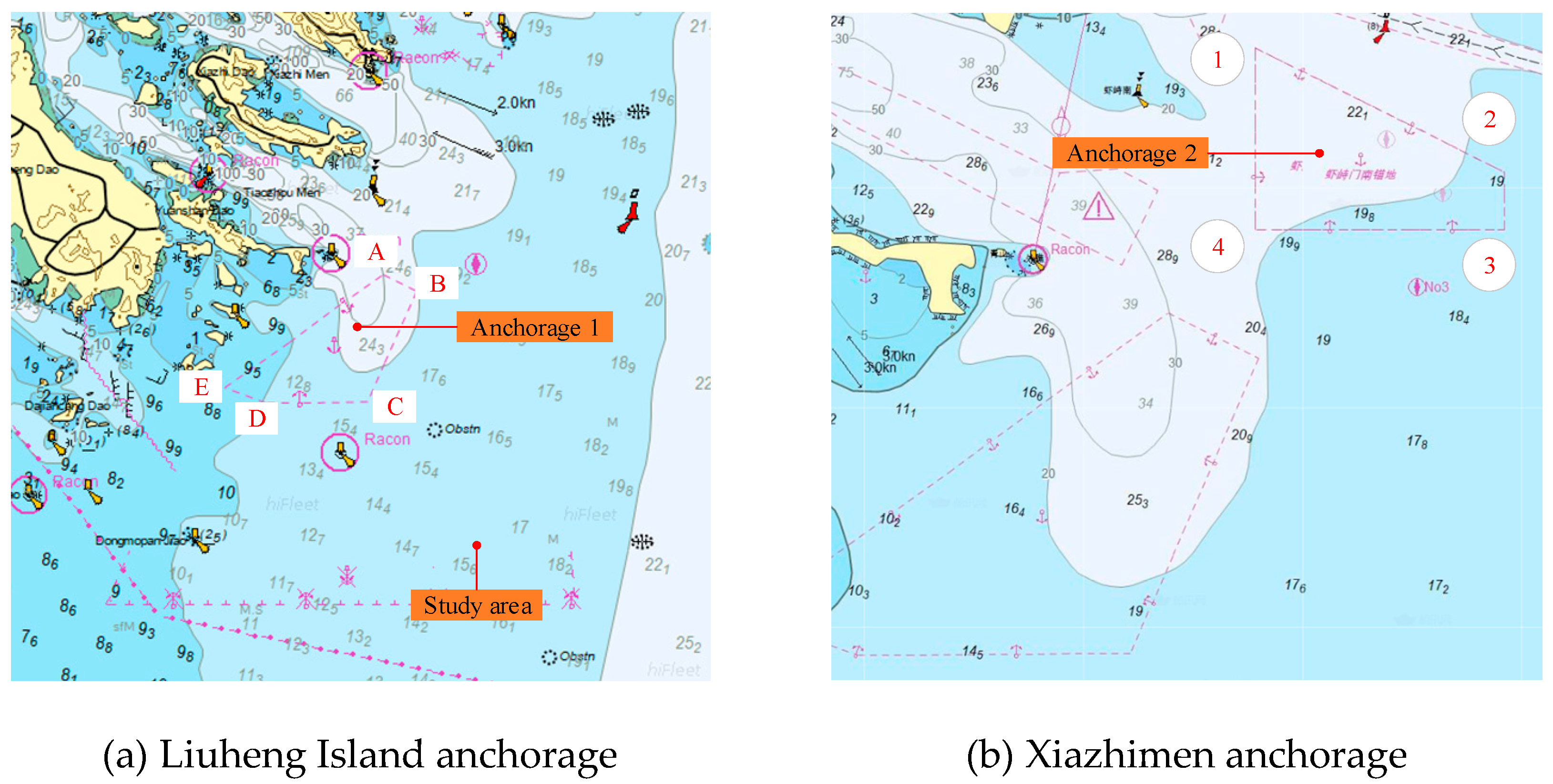
Figure 12.
The optimal anchorage position of the map and the heat map
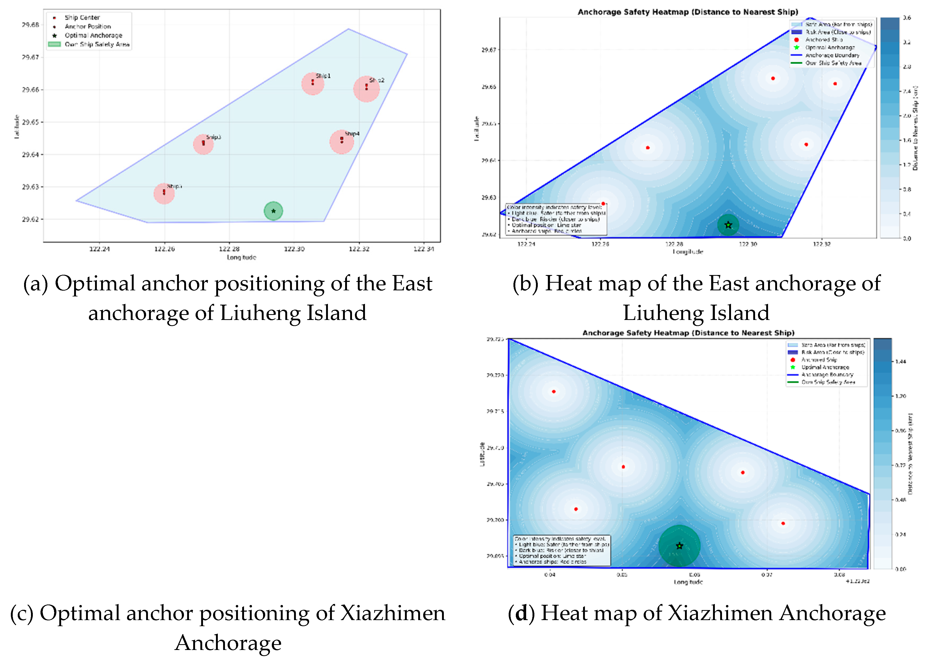
Figure 13.
Planned and. actual trajectories under 270° and 330° environmental forces
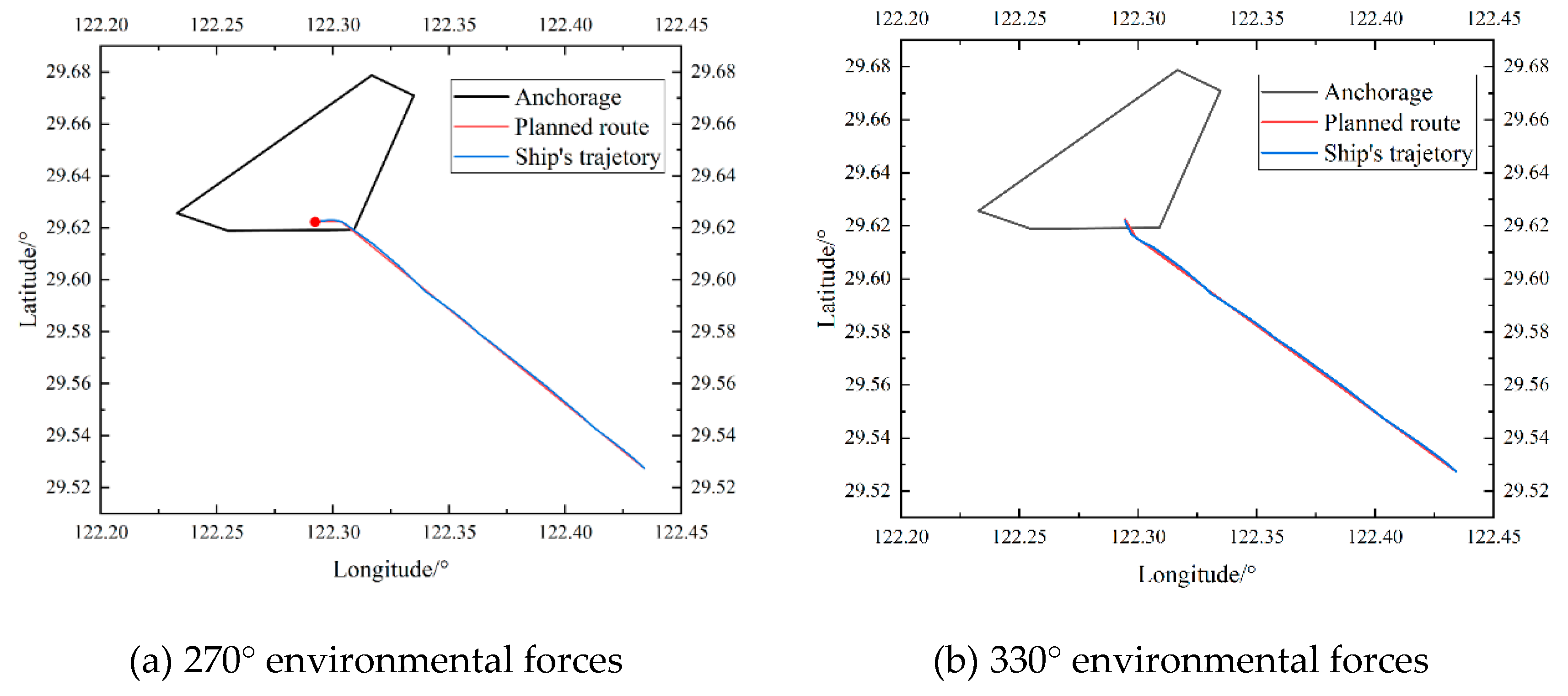
Figure 14.
Ship state during the anchoring manoeuvre in Speed over ground and Heading
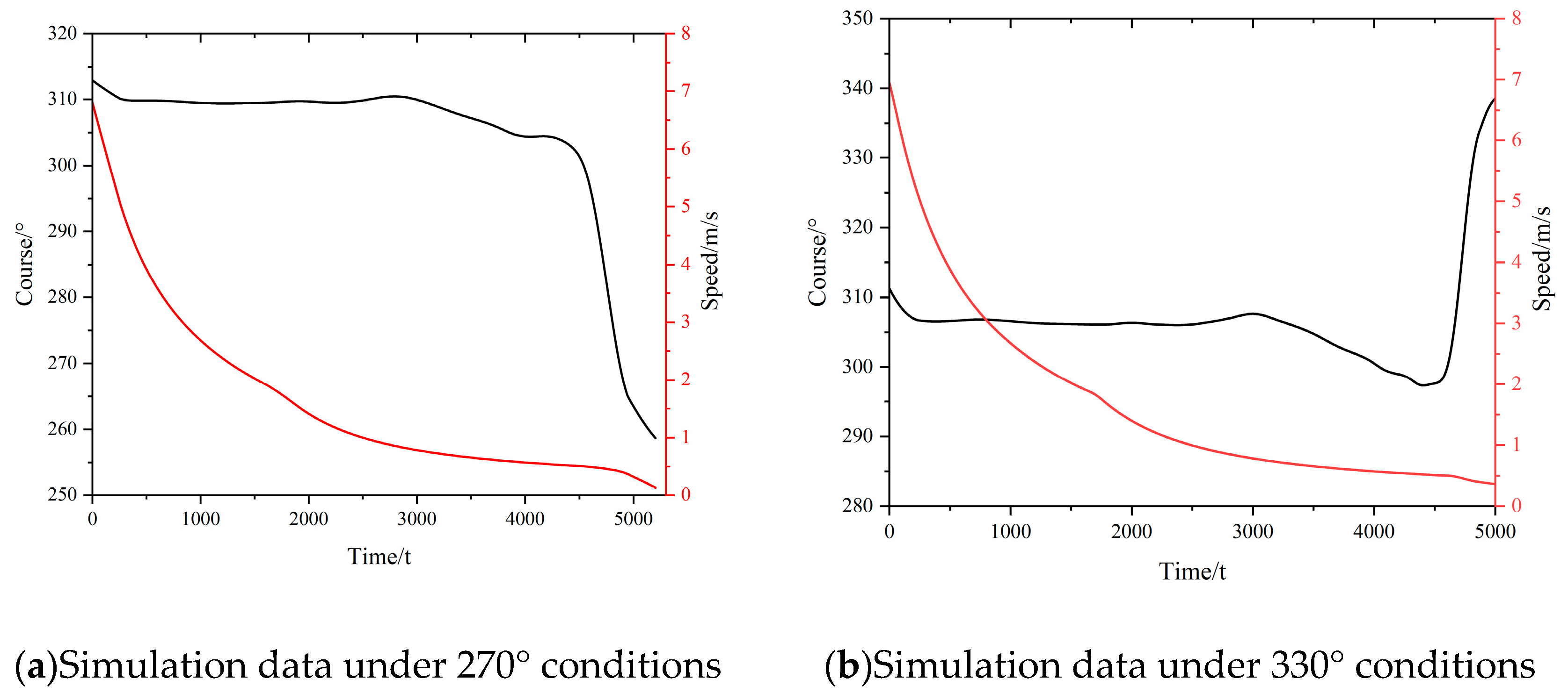

Table 1.
Geographical boundaries of the anchorages
| Item | Latitude/N | Longitude/E | Item | Latitude/N | Longitude/E |
| A | 29°40.723 | 122°19.002 | 1 | 29°43.506 | 122°20.057 |
| B | 29°40.256 | 122°20.089 | 2 | 29°42.212 | 122°23.054 |
| C | 29°37.158 | 122°18.547 | 3 | 29°41.591 | 122°23.033 |
| D | 29°37.134 | 122°15.29 | 4 | 29°41.609 | 122°20.047 |
| E | 29°37.541 | 122°13.967 |
Table 2.
Parameters of anchored ships in the experimental scenario
| Item | Latitude/N | Longitude/E | Length/m | |
| 1 | 29.662756° | 122.305715° | 220 | East anchorage of Liuheng Island |
| 2 | 29.661407° | 122.322277° | 280 | East anchorage of Liuheng Island |
| 3 | 29.643863° | 122.271988° | 180 | East anchorage of Liuheng Island |
| 4 | 29.644913° | 122.314640° | 245 | East anchorage of Liuheng Island |
| 5 | 29.628717° | 122.259888° | 190 | East anchorage of Liuheng Island |
| 6 | 29.718251° | 122.339540° | 220 | Xiazhimen Anchorage |
| 7 | 29.702141° | 122.342329° | 280 | Xiazhimen Anchorage |
| 8 | 29.707761° | 122.349323° | 180 | Xiazhimen Anchorage |
| 9 | 29.707124° | 122.365543° | 245 | Xiazhimen Anchorage |
| 10 | 29.699968° | 122.371378° | 190 | Xiazhimen Anchorage |
Table 3.
Particulars of the ship
| Draft | Length | Breath | Displacement | Water density | Initial Position |
| 14.5m | 229.2m | 32.2m | 88 000 Tons | 1 025 kg/m3 | 122.434177E/29.527429N |
Disclaimer/Publisher’s Note: The statements, opinions and data contained in all publications are solely those of the individual author(s) and contributor(s) and not of MDPI and/or the editor(s). MDPI and/or the editor(s) disclaim responsibility for any injury to people or property resulting from any ideas, methods, instructions or products referred to in the content. |
© 2025 by the authors. Licensee MDPI, Basel, Switzerland. This article is an open access article distributed under the terms and conditions of the Creative Commons Attribution (CC BY) license (http://creativecommons.org/licenses/by/4.0/).
Copyright: This open access article is published under a Creative Commons CC BY 4.0 license, which permit the free download, distribution, and reuse, provided that the author and preprint are cited in any reuse.


