
Submitted:
27 November 2025
Posted:
28 November 2025
You are already at the latest version
Abstract
Ammonia, as a carbon-free energy carrier, is gaining prominence for hydrogen storage and power generation applications due to its high energy density and ease of transport. However, the practical adoption of ammonia in combustion systems faces major stability challenges—chiefly its low reactivity, slow laminar burning velocity, narrow flammability envelope, and high ignition temperature. These attributes increase the risks of flame instability, misfire, and incomplete combustion, which, in turn, can elevate levels of unburned ammonia and greenhouse gas emissions such as NOx—posing significant health and climate concerns. Stable ammonia combustion demands optimization of several interrelated factors: the air–fuel equivalence ratio, flame temperature, flow regime, and combustor design are critical for maintaining reliable operation. Particularly pivotal is the control of the air–fuel equivalence ratio; excessively lean conditions can trigger flameout. Modern systems utilize real-time monitoring of flame and exhaust properties to diagnose and prevent instabilities. Advanced combustion strategies, such as transitioning to diffusion or flameless (MILD) regimes, substantially expand the stable operating window, especially under lean conditions. Overall, sustaining stable ammonia combustion is essential for maximizing efficiency and emission control, and integrating aftertreatment (deNOx) technologies is crucial for sustainable, clean-energy implementation.
Keywords:
ammonia
; combustion stability
; flameless combustion
; renewable energy
; NOₓ reduction
; hydrogen production
1. Introduction
Combustion instability has been observed in most of the combustion processes like gas turbines, rocket motors, power plants steel, cement, and food production. Technological challenges associated with ammonia combustion that cause stability problems. Unstable combustion conditions can lead to nonuniform thermal distribution, high pollutant emissions, low efficiency, furnace vibration, and safety issues [1].
Ammonia is widely utilized as a carbon-free fuel in internal combustion engines because of its high energy content and broad availability. The low reactivity, slow burning ignition temperature of ammonia and NOx emission are crucial challenge for the combustion stability[2].
The operating conditions of an ammonia combustion system can have a significant impact on its flame stability (A: stable flame, B: unstable flame, C: flameless condition), and the risk of extinction. Some of the key factors that affect flame stability (Figure 1) are including pressure, temperature, equivalence ratio, flow velocity, exhaust gas recirculation ratio kv, air and fuel injection methods and nozzle types as well as combustion mode [2,3].
The temperature in the combustion system impact flame stability. Due to the ignition temperature of ammonia before 800 °C there is no combustion reaction. Higher temperatures can lead to higher flame speeds and improved stability but can also cause the combustion reaction to become more exothermic, resulting in elevated flame temperatures and consequently increasing the likelihood of thermal runaway.
The pressure in the combustion system can also affect the flame stability by changing the density of the gases and the rate of heat transfer. Generally, a decrease in pressure will cause a decrease in flame stability, as the lower density of the gases makes it more difficult for the fuel and air to mix and for heat to transfer.
The equivalence ratio, or the ratio of fuel to air in the combustion system, affects the flame stability by changing the rate of reaction and the availability of oxygen. An increase in the equivalence ratio can improve flame stability by increasing the fuel concentration but can also increase the risk of over-firing and thermal runaway [2].
The flow velocity of the fuel and air in the combustion system affects the flame stability by changing the mixing characteristics of the fuels and the speed of the reaction. Higher flow velocities can improve flame stability by promoting better mixing but can also cause the flame to become more unstable and susceptible to extinction if the flow becomes too fast. The presence of inert species, such as nitrogen and carbon dioxide, in the combustion system can affect the flame stability by reducing the availability of oxygen and changing the heat transfer characteristics of the system. The Lewis number, low laminar burning velocity, and Damkohler number where the indicators can be used to measure the thermal stability. By understanding the effects of these parameters on flame stability, they can design and operate ammonia combustion systems that are controlling flame stabilizing. In some cases, flame stabilizers, such as catalysts or flame rods, may be used to improve flame stability and reduce the risk of extinction [4].
The high chamber temperature, a well reactive zone and a stable environment perpetually start the combustion. In the reaction zone, the fuel and oxidizer undergo a chemical reaction through convection and diffusion whereby both the fuel and oxidizer blend prior to the chemical reaction. The proportions of burnt gases are quite low. The rate of combustion is usually controlled by the transport and mixing mechanisms and not by the chemical reaction, which leads to increased stability in the flame [5].
1.1. The Characteristic of Ammonia Combustion Instability
Instabilities manifest in various fluid flows, such as water flowing from a tap, smoke emanating from an incense stick, and the flow between two concentric cylinders, as well as in a layer of heated liquid. Within combustion chambers, combustion stability becomes a paramount concern, often stemming from robust pressure oscillations resonating at specific acoustic modes. These resonant pressure oscillations inflict substantial thermal loads, ultimately resulting in the mechanical failure of the chamber. [6].
Industrial boilers and furnaces sometimes develop low-frequency vibrations because of the way the burner interacts with the acoustic behavior of the combustion chamber or the ductwork connected to it. In simple terms, pressure waves created by acoustic resonances travel back to the burner, where they match up with natural fluctuations in the combustion process caused by turbulence and chemical reactions. When these pressure waves line up with the flame’s heat-release fluctuations, the normal damping forces that would usually weaken the pressure waves can no longer do their job. As a result, a self-reinforcing feedback loop forms, causing the vibrations to grow stronger instead of disappearing. These oscillations, known as thermoacoustic oscillations or rumble, have been extensively studied due to their potential to negatively impact thermal efficiency, emissions, and cause mechanical vibrations leading to structural damage [6].
Dealing with rumble is a real challenge for combustion engineers because it is hard to predict and can be influenced by many different design and operating factors. Things like fuel quality, burner swirl and staging, the behavior of induction and draft fans, duct design, and even the shape of the combustion chamber can all play a role. These factors interact in complex ways, which is why two boilers or furnaces that look identical on paper can behave very differently in practice—one may run smoothly while the other develops rumble problems. Identifying the causes of thermoacoustic vibrations in industrial burners and improving diagnosis and remediation methods is crucial to mitigate these effects. [7].
Combustion instability manifests in various ways, impacting system performance and combustion characteristics. Under specific conditions, unstable combustion may even enhance the system's performance by promoting the mixing of fresh and exhausted gases. However, the occurrence of thermoacoustic combustion instabilities, marked by rising pressure and heat release oscillations, often results in detrimental effects [7].
In such instances, the flame front tends to be confined to the surfaces of large vortexes in the primary region of the burner quarl. This non-uniform thermal distribution leads to local thermal peaks, causing an increase in thermal NOx and a reduction in reaction rate. Oscillations of significant amplitude signify undesired combustion behavior, resulting in abrupt reductions in system performance [7].
Commonly, three general classes of instabilities are distinguished: chamber instabilities, intrinsic instabilities, and system interaction instabilities. Instabilities inside combustion chambers are a natural part of how flames behave. For example, premixed flames can show hydrodynamic instability, known as the Darrieus–Landau instability, and they can also become thermo-diffusively unstable when the Lewis number is not equal to one. These types of intrinsic instabilities arise because the combustion process interacts and couples with the acoustic behavior of the system, making the flame sensitive to pressure and flow disturbances. The resonant modes ensuring feedback typically have a plane nature, with wavelengths equivalent to the total system longitudinal dimension. System interaction instabilities involve interactions with feed and exhaust, generally characterized by low-frequency oscillations (subsonic) [7].
In the third category, combustion is still linked to acoustic modes, but these modes are tied to the chamber’s natural resonances. They often appear as vibrations or oscillations that move sideways (transverse) or around the chamber (azimuthal), rather than simply back and forth.The wavelength associated with the third category is determined by the chamber diameter, resulting in oscillations falling within the high-frequency range (supersonic) [7].
Detecting combustion instability can be achieved through innovative deep learning models based on high-speed flame images captured from a combustion system. The efficacy of these models is demonstrated through validation using a dataset of high-speed flame images obtained in a gas turbine combustor during transitions from stable to unstable conditions and vice versa. The proposed models exhibit exceptional performance across all test cases, achieving high accuracy levels ranging from 95.1% to 98.6%. This deep learning approach proves to be a promising tool for the identification and prediction of combustion instability[6,8].
During the transition from stable to unstable flame, which is caused by changes in fuel composition, a novel methodology can detect multiple modes of combustion instability effectively in a gas turbine combustor, as well as dynamic pressure and flame images [9]. In this technique, spectral analysis of dynamic pressure is used to develop a new filter bank method. Sequential processing with a triangular filter with Mel-scaling and Hamming window is utilized to enhance the accuracy of the method. By determining the magnitude of filter bank components, the instability criterion is determined. It is shown that the filter bank method performs well than two conventional methods based on root-mean squared dynamic pressure and temporal kurtosis. Based on the results, the filter bank method shows comparable performance in terms of detection speed, sensitivity, and accuracy to other methods. Moreover, the filter bank components enable the analysis of various frequencies and multi-mode frequencies. The filter bank method can, therefore, be considered as an additional prognosis tool for determining multi-mode combustion instability in a gas turbine combustion monitoring system [10].
1.2. Thermal Diffusive Instability of Ammonia Combustion
Thermal instability often occurs when a fluid is heated from below. If the temperature difference becomes large enough, the buoyancy forces created by the hot, rising fluid can overpower the stabilizing effects of viscosity and thermal conductivity. When this happens, the fluid becomes unstable and begins to circulate or form convection patterns.
An overturning instability occurs as a result of thermal convection The stability of an ammonia combustion flame is an important factor that affects its efficiency and safety. A stable flame is one that burns steadily and uniformly, whereas an unstable flame flickers, flaps or changes shape, and may eventually extinguish itself. Thermal instability occurs when there is a rapid change in the temperature of the flame, leading to a disturbance in the heat release rate and resulting in fluctuations in the combustion process. This type of instability can be caused by a variety of factors, including changes in the air/fuel ratio, variations in the heat transfer rate, and fluctuations in the flame temperature [11].
Flame instability results from the interplay of both transport processes within the flame, particularly diffusion-thermal processes influenced by its structure, and hydrodynamic processes influenced by the gas flow. Addressing practical issues in the theory of combustion involves determining concentration limits for flame propagation, ignition, and extinction, as well as understanding spontaneous instability of the flame front, the transition from combustion to detonation, and the excitation of oscillations during combustion.
Acoustic combustion instability can be thought of as a self-sustaining oscillation. Even though the combustion process itself is not periodic, it can feed energy into sound waves, allowing them to persist without dying out. This happens because the acoustic waves, in turn, influence the way the flame releases heat, creating a continuous feedback loop. In this situation, the characteristics of the oscillations—such as their amplitude, shape, and frequency—are determined by the system’s own internal properties rather than by any external forcing. [10]. The most of thermal stability indicators are including maximum reaction pressure, adiabatic temperature rise due to heat of reaction, Lewis number as a function of reactants, low laminar burning velocity, and Damkohler number, etc.
Comparing to methane, ammonia has narrow stable flame range as shown in Figure 2. Lean blowout occurs at ϕ=0.70 for NH3-air and at ϕ=0.53 for CH4-air flames. Decreasing XNH3 reduces the equivalence ratio at the lean blowout. Just 5% of CH4 or H2 improves the lean stability limit of NH3 combustion. Ammonia addition up to XNH3 = 0.70 does not drastically modify the stability. N2 in cracked NH3 reduces the mixture reactivity and narrows the lean stability limit. The higher the pressure results in the leaner the stable limit. Consistent with extinction measurements, NH3-H2 flames are less susceptible to blowout than NH3-CH4 flames [12].
Measurements of a spherical ammonia-oxygen flame in a constant volume chamber focus on key parameters, including laminar flame speed, the Markstein length, laminar flame thickness, and critical radius of flame instability. Utilizing different initial pressures (0.5 to1.6 atm) and equivalence ratios ∅ (0.5, 0.75, 1.0, 1.3, 1.75), flame propagation is examined using a high-speed digital Schlieren photograph system (Figure 3). The investigation reveals a maximum laminar flame speed of 1.09 m/s in the ammonia/oxygen mixture. Notably, as the initial pressure increases, the flame thickness decreases. The Markstein length increases with higher equivalence ratios, whereas it decreases with an increase in initial pressure. The minimum critical radius is measured at 1.8 cm in ammonia/oxygen, and it decreases with the increase of initial pressure [13,14].
The adiabatic flame temperature of ammonia air combustion increases slightly with the air and the conical probe in the flame, with a high degree of stability [15].
In convective–diffusive scaling, the cube root of the Zel'dovich number predicts striped patterns for flames close to quasi-steady extinction with a finite wavenumber. As a result of the convective–diffusive response, the flame becomes more resistant to instability by stabilizing long-wavelength disturbances by creating positive excess enthalpies. The reaction-zone response, on the other hand, stabilizes short-wavelength disturbances through transverse diffusion within the reactive inner layer, resulting in the relaxation of perturbed scalar fields in their unperturbed state. In an intermediate range between these two scaling, marginal stability emerges first as quasi-steady extinction approaches. Numerical solutions to the associated generalized eigenvalue problems provide parametric results for this bifurcation point. It has been discovered that there is excellent qualitative agreement between the measured pattern dimensions and the measured pattern dimensions for different sets of reactants and diluents [16].
The diffusional-thermal instability responsible for striped quenching patterns in diffusion flames is investigated by considering the model of a onedimensional convective diffusion flame operating in the diffusion flame regime of activation energy asymptotic. There is a great deal of attention paid to near extinction conditions with Lewis numbers less than unity, during diffuse of which high diffusivity reactants into the strong segments of the reaction sheet, resulting in a deficiency of reactants in the regions between the strong segments that causes local quenching, resulting in stripes. In contrast to other analyses of flame stability, this analysis utilizes a composite expansion of convective-diffusive scaling and reaction zone scaling to determine the dispersion relation [16].
The cellular instability of the premixed mixture is which causes by diffusive-thermal instability and hydrodynamic instability. Premixed flames and diffusion flames exhibit diffusional-thermal instability. There is a difference in diffusion coefficient values for fuel and heat transport, which is characterized by values of Lewis numbers less than unity. If the effective Lewis number is less than unity, the flame becomes unstable, while if it is greater than unity, the expanding flame will become stable due to diffusional-thermal instability [17].
The Lewis number (Le) is often described using the strength of the diffusive imbalance that leads to diffusional–thermal instability as folowing equation:
where DT (thermal diffusivity) and DM (the mass diffusivity) are coefficient of species into the diluent; λ the unburnt gas thermal conductivity in W/(m⋅ K); CP the specific heat at constant pressure in kJ/(kg⋅k).
Le = DT/ DM = λ /ρu .Cp .DM
For the flames of the reactants 50%NH3 and 50%H2 with air, the volume-weighted method used to calculate the effective Lewis number (Leeff)
where XH2 is the volume fraction of H2; XNH3 is the volume fraction of NH3; LeH2 is the Lewis number of H2; LeNH3 the Lewis number of NH3, and approximately is 0.34 for H2 and 0.95-1.0 for NH3,in air at ambient temperature and pressure, and Leeff value would be 0.645 [2].
Leeff =XH2 LeH2 + XNH3 LeNH3
Observations of freely propagating, adiabatic premixed flames with finite activation energies show that there is no pulsating instability in regimes predicted to be unstable by asymptotic analysis. Although only below a critical Lewis number of the fuel, the flame is unstable, the finite activation energy results are qualitatively consistent with the asymptotic results, i.e., the flame becomes more unstable as the Lewis number decreases. For the asymptotic analysis to be quantitatively predictive, very high activation energies are required. As a result of a lower fuel Lewis number being required for flame instability for finite activation energies, the flame appears to be less unstable than predicted by the asymptotic analysis. The flame structure and stability may also be affected by the activation energy in a nonmonotonic manner [2].
1.3. Hydrodynamic Instability Characteristics of Ammonia Combustion
Hydrodynamic instability occurs when there is a disturbance in the flow of the reactants and the combustion products. This type of instability is typically caused by turbulence in the combustion chamber, which can result in fluctuations in the velocity of the air flow, leading to changes in the mixing of the fuel and air. Hydrodynamic instability is caused by expansion across the flame surface, which is characterized by the σ thermal expansion ratio and δ flame thickness [18,19].
The hydrodynamics stability of compressible boundary layers is significantly affected by the Mach number (M), Prandtl number (Pr), and thermal wall boundary conditions. These influences prominently the stability of the flow through the interactions between flow dynamics and thermodynamics. Strouhal number (St) at the location of shear layer results in a high flame speed, which is three times greater than the stoichiometric methane/air flame speed (0.43 m/s) at room temperature. The Strouhal number (St) is calculated by:
where f is the frequency(Hz), D is the diameter( cm) of the swirler exit, Ud the bulk velocity( m/s) at the swirler exit.
St = f⋅D/Ud
The hydrodynamic instability demonstrated a monotonically increasing trend with rising pressure and exhibited non-monotonic variations with increasing Stoichiometric ratio. On the other hand, thermal-diffusive instability experienced a significant increase with higher Stoichiometric ratios but showed less sensitivity to pressure variations. Evaluating the critical conditions for the transition from stable to unstable flame states revealed that the critical Peclet number decreased monotonically with an increase in Stoichiometric ratio. This implies that fuel-rich flames are more susceptible to severe cellular instability compared to fuel-lean flames. Additionally, the critical flame radius decreased as pressure increased, a consistent observation in both experimental measurements and theoretical calculations. [20].
Comparing the simulations with the Kolmogorov power law reveals that the LES is capable of capturing more than two orders of magnitude of TKE for the inertial subrange of the energy spectrum [21].
Figure 4 Illustrates the effects of H2% (E10-H30-S07) compare with a low flame speed, for comparing dry and steam condition (E05-H30-S0 and E06-H30-S01) and (E12-H30-S06) for the rich combustion at equivalence ratio 1.2 [21,22].
The turbulent kinetic energy spectrum of a10 kW premixed ammonia combustion blends of NH3/H2/N2/H2O – air at equivalence ratio 0.5-1 (E), H2% 0.30-0.75 (H), and steam-to-air ratio 0.1-0.9 (S) with the Strouhal number at the location of shear layer Illustrated by Figure 4 [21].
For a lean-premixed flame stabilized behind a circular cylinder, hydrodynamic instability for Lewis number Le > 1, is directly proportional with equivalence ratio and pressure. On reducing the equivalence ratio (ϕ) at a fixed Reynolds number (Re), it is found that the flame transitions from a steady mode to a varicose mode and then to a sinuous mode [21].
The lean blowout process in propane turbulent premixed combustion is investigated using high-speed particle imaging velocimetry and CH chemiluminescence (Figure 5).
There is a significant relationship between flame extinction and flame-vortex dynamics, that is, an increase in downstream shear layer vorticity is coupled with a decrease in flame-generated vorticity. The vorticity dynamics become more unstable as the equivalence ratio decreases. To characterize the dynamic changes in hydrodynamic instability modes during flame extinction, a frequency analysis is performed. In order to further characterize extinction instability modes, various bluff body inflow velocity regimes are investigated. For reacting bluff body flows, the Strouhal number is used to capture both equivalence ratios and flow-driven instabilities. For different regimes of inflow velocity, a Karlovitz number can be used to predict the onset of global extinction [23,24].
Darrieus-Landau (DL) instability of premixed flames, which is caused by the expansion of gas following combustion, causes hydrodynamic disturbances that enhance the perturbations of the flame front in turbulent flows [25].
The hydrodynamic flame instability or Darrieus-Landau (DL) instability occurs when the heat of combustion expands the gas, thereby enhancing perturbations of the turbulence intensity flows along the flame front. A corrugated flame is created with sharp edges pointing toward the burned gas. Flames with DL instability appear as turbulent flames and form cusp-like conformations with elongated intrusions pointing toward the burned gas region. Due to their larger surface area, these structures are stable and propagate at a speed that is significantly faster than that of laminar flames. Flames with weak-to-moderate turbulence intensity appear to be affected by the DL instability [25].
Viscosity, heat conduction, and species diffusion all have significant effects on flame stability. These influences were highlighted in studies that sought to improve the classic Darrieus–Landau (DL) analysis by incorporating more realistic physical behavior, as well as in asymptotic analyses that revealed explicit relationships between stability and key physical parameters. Hydrodynamic instability, meanwhile, is an inherent feature of flame propagation and is directly connected to the expansion of combustion products as the flame moves [25].
Hydrodynamic instability increases as the thermal expansion ratio (σ) becomes larger and decreases as the laminar flame thickness (δ) grows. In other words, stronger expansion across the flame front makes the instability more pronounced, while a thicker flame tends to calm it down. [25,26]. The thermal expansion ratio σ can be determined by δ, the laminar flame thickness, using the following equation:
δ= λ/(CP. ρu. SL)
Under adiabatic wall boundary conditions, an increase in the Prandtl number (Pr) leads to a destabilizing effect. The relationship between Mach and Pr influences the behavior of production, pressure-strain correlation, and pressure-dilatation. While the first and second instability modes display similar stability trends, the fundamental flow physics underlying them are revealed to be diametrically opposite. The impact of Pr on instability is elucidated by considering the base flow profile in relation to various perturbation mode shapes.
The Pr of ammonia are bigger than 1, (1.38 for gaseous ammonia), which indicates that momentum is higher than heat dissipate through the fluid at about the same rate [27].
In simple terms, instability occurs when energy moves from a smooth, organized flow into small, disorganized disturbances. As these velocity disturbances grow and become large enough compared to the main flow, nonlinear effects start to dominate. This causes the orderly flow to break down and transition into turbulence, where the motion becomes irregular and chaotic. During this shift from a neat laminar flow to a turbulent one, the way mass, momentum, and energy are transported through the system changes dramatically[27].
Hydrodynamic stability of a planar flame front of finite thickness is investigated in relation to flow compressibility. As the Mach number of the flame generated flow increases, a flame front becomes more unstable. A flame in an incompressible flow grows at a rate two–three times faster than a flame in a flow with a Mach number of 0.1–0.2 [28].
The Figure 6 illustrates the wavelength disturbances in terms of weighted average of the fuel and oxidizer Lewis numbers Leeff. Leeff < Le*eff the short wavelength disturbances are also unstable hydrodynamic instability which is enhanced by diffusion effects. Leeff > Le*eff the short wavelength disturbances (λ > λc= 2π/kc) are stabilized by diffusion hydrodynamic instability can be applied for hazard assessment of ammonia detonation[25].
In order to determine the hydrodynamic stability of a planar flame (deflagration), the complete system of equations must be solved, including thermal conduction and energy release due to chemical reactions. This theory provides a rigorous justification of the Darrieus-Landau assumption that the flame-front velocity is constant as a result of large-wavelength perturbations, which is the necessary supplementary condition in the discontinuous flame front model. Analytical solutions are obtained for an arbitrary activation energy for the suppression of flame-front instability. The obtained solution does not depend on the form in which energy is released. In addition to finding the perturbation growth rate numerically, the eigenvalue problem is also used to find the perturbation growth rate [28].
1.4. Thermoacoustic Instability Characteristics of Ammonia Combustion
The stability of combustion is a critical issue in most combustion chambers. Combustion noise and thermoacoustic instabilities are two types of combustion instability. In both cases, combustion is the driving force, but their characteristics and physical phenomena are different.
As a consequence of strong pressure oscillations resonating at specific acoustic modes, modern combustion chambers are at risk from thermoacoustic combustion instabilities, due to strong pressure oscillations resonating at specific acoustic modes. which occur as pressure and heat release fluctuations with large amplitudes and low frequencies [29].
Thermal-acoustic flame instabilities influence gas turbine emissions. Engine components are susceptible to severe structural damage, reduced operability, and inefficiency due to the coupling mechanisms of combustor acoustics and combustion heat release fluctuations [30].
Analyzing combustion acoustic phenomena using large eddy simulations reveals that resonance pressure oscillations cause severe thermal load, resulting in the mechanical failure of a chamber in compression-ignition engines [31]. When the flame front and the acoustic field inside the chamber are coupled in phase, the oscillations of both variables are amplified. A coupling mechanism produces oscillations that self-sustain and cause combustion to become unstable, usually generating resonant acoustic modes in the combustion chamber or causing chaos in the combustion process[32].
When pressure fluctuations in the combustion chamber are coupled with the rate at which heat is released, thermoacoustic instability occurs. As a result of fluctuations in flame temperature, this type of instability can result in changes in the pressure waves generated by the combustion process [33].
During gaseous combustion, sound is emitted according to the classical set of mass, momentum, and energy conservation equations. An oscillation with a large amplitude is a common symptom of thermoacoustic instabilities. Instabilities are spontaneously generated and oscillations are maintained through a feedback loop between combustion and the acoustic field. Acoustic noise can be generated by unsteady combustion [34,35]. Acoustic waves are generated by the unsteady heat release in the flame, which are reflected at the boundaries of the system, resulting in standing waves. Acoustic fluctuations result in flow and mixture perturbations, which in turn affect the flame, resulting in a fluctuation in the heat release. Thus, the loop is closed. Depending on the phase between the heat release and the pressure, the oscillations will be amplified or damped. As opposed to combustion noise, thermoacoustic instabilities exhibit oscillations of distinct amplitudes and frequencies [35].
The complex network analysis method with machine learning is used to identify thermoacoustic instability driven by combustion. By examining the probability distribution of transition patterns in ordinal partition transition networks, researchers can detect subtle shifts in the combustion state as it moves from low-level combustion noise to strong thermoacoustic instability. Using a support vector machine (SVM), the system is able to recognize early warning signs of instability. This is done by creating a feature space from the principal component plane, which is estimated using the transition-pattern probability distribution[36]. Early detection of thermoacoustic combustion instability using a methodology[37].
The occurrence of ammonia combustion instabilities is effectively addressed through the implementation of an active control system using a neural network PID controller. This controller proves capable of suppressing oscillating pressure, effectively mitigating and eliminating system pressure oscillations across various oscillating stages with different flame models [37,38].
In a lean premixed pre-vaporized, multi nozzle gas turbine model combustor, the impact of fuel variations on thermoacoustic instability characteristics as well as flame/flow dynamics was investigated experimentally with high-speed particle image velocimetry and flame OH chemiluminescence measurements.
As the adiabatic flame temperature rises, the instability frequency also increases. Meanwhile, the fuel’s ignition delay and heat-release characteristics largely determine how strong those instabilities become. Analyses using phase-averaged sequences, spectral methods, and proper orthogonal decomposition (POD) of instantaneous measurements show that the unsteady behavior in a multi-nozzle combustor is dominated by large-scale longitudinal oscillations and by side-to-side interactions between neighboring flame roots. These motions play a major role in shaping the overall flame and flow dynamics. [32,39].
1.5. Elemental Analysis of Combustion Flow and Instability
The instability during ammonia combustion process depend on various factors such as air preheating temperature, reaction zone temperature, pressure, and reactant concentrations involving several chemical species and mechanism reactions. Ammonia combustion instability is occurring when the combustion process in an ammonia-air burner becomes unstable, leading to fluctuations in flame intensity and temperature. Analyzing ammonia combustion instability is an important step in evaluating the safety of systems that use ammonia as a fuel or a reactant to prevent damage to equipment and ensure the safety of personnel. It is typically involves monitoring the pressure and temperature of the combustion system[2].
The flameless combustion techniques have been examined under reacting conditions employed for the analysis. The power 2.5 kW and air flow rate from 30 to 170 lpm, at equivalence ratio 0.2-1.2, and pressure 0.10 MPa. Variations in equivalence ratio, were set to fixed concentrations of ammonia NH3 and then air velocity was changed.
NOx emission of the NH3–air combustion changes with temperatures and time under the different the equivalence ratio conditions. It is a result of the fuel-NOx from the fuel-bond nitrogen in NH3 and thermal-NOx from the oxidation of N2 in air, at very high temperature.[40,41].
The Reynolds number is the ratio of inertial forces to viscous forces.
NRe=ρ.v.d/μ= 21.8647V
The experiments were carried out for ϕ = 0.2– 1.2 and velocity of ammonia is 2.1263 m/s and air velocity are in range variety of 17.686- 99.0449 m/s. Therefore, Reynolds number for ammonia is 88.30 which is laminar and for air, Re is in the range of 3242.4 to 18370, indicates that the air flow is transitional and turbulent flow at ambient condition.
Strouhal number is a dimensionless number describing oscillating flow mechanisms and decrease with an increasing Reynolds number. The higher-frequency Strouhal number is caused by small-scale instabilities from the separation of the shear layer. The Strouhal Number (St) is used in the analysis of unsteady, oscillating flow problems. It varies depending on oscillation frequency ω, characteristic length L, and flow velocity V as following equation:
St = ω .L / V
The evaluating applicability of Strouhal number to describe oscillating flow mechanisms.
Reynolds and Strouhal number corresponding to the inlet air mass flow rates and velocities, in ammonia flameless combustion. The Reynolds number, and Strahoul number, among the non-dimensional parameters can predict ammonia flameless s combustion instability because others are applicable only for predicting flame stability.
Some factors effect on ammonia combustion instability include: low total excess air, concentration of O2 and NO2 in outlet gas, insufficient residence times of the injecting mixture jet (blow-off). The impact of instability on unburned ammonia, NOx emissions (ppm) and % O2 expected. The reaction pathway involves the formation of intermediate species such as NO, N2O, H2, and OH. The concentrations of these intermediate species can impact the stability of the reaction and the formation of the final products[2].
Measuring factors associated with ammonia combustion instability such as the pressure and temperature signals that can be used to detect fluctuations and combustion instabilities in real-time, while the exhaust gas analysis provides information about the complete combustion process and helps to identify any incomplete combustion that may lead to increased emissions of harmful by-products such as NOx in addition to unburned ammonia, as well as the concentration of ammonia in the exhaust gases.
Fluctuating flame intensity, in the combustion chamber may appear to flicker or change in size, indicating instability in the combustion process. The key parameters affecting the combustion process are ammonia and air flow and its distribution in the combustor, temperature and pressure of inlet air that are influenced by ambient conditions, compressor performance, load, grid frequency, fuel nozzles and combustion chamber design and condition[2].
To perform a stability measurement, the thermocouple sensors, are placed in the combustion chamber to measure the temperature fluctuations. The sensor signals are then analyzed to determine the frequency and magnitude of the fluctuations. This information can be used to identify areas of the combustion system that are prone to instabilities and to optimize the system design and operation to ensure safe and stable combustion. Methods for evaluating thermal instability in ammonia combustion can have serious safety consequences, including the potential for explosions and release of toxic gas. The high temperatures and fluctuations in the combustion process can cause damage to equipment and a risk to personnel working in the vicinity of the equipment. Additionally, the release of toxic gases, such as nitrogen oxides (NOx) and unburned ammonia, harmful to human health in the workplace and the environment[2].
2. Combustion Methods and Stability
Identifying gaps in the understanding of ammonia combustion stability is essential for rigorously assessing how various combustion methods and burner configurations influence stable flame operation. Current knowledge lacks detailed comparisons across different burner geometries, ignition schemes, and operational regimes—especially regarding how these factors affect flame propagation, blowoff limits, and sensitivity to equivalence ratio and temperature. Systematic evaluation of burner and combustor designs, such as swirling, non-swirling, premixed, and flameless systems, remains incomplete, and diagnostic techniques to track instabilities under transient or boundary conditions are not yet fully established. Addressing these deficiencies is crucial for developing reliable ammonia-fueled systems that maximize energy efficiency and minimize harmful emissions, while ensuring safe and controllable combustion across a range of applications.
In the diffusion flame, the fuel and mixture are combined in a furnace and ignite when they encounter each other. For safety reasons, many combustors operate in nonpremixed mode. Because the fuel and the oxidizer are not premixed, a sudden combustion (explosion) is not possible.
Flameless combustion involves the interaction of three essential components: fuel, air, and recirculated combustion products, which forms a gas with a temperature exceeding its autoignition temperature. The combustion will take place in an oxygen-poor atmosphere, due to the watering down of the gas that burns [1,29].
In the flameless combustion, there are no temperature variations. The most remarkable effect in flameless combustion is the appearance, which is created when the oxygen content of the air is minimal (less than 2%) [3,42].
Temperature increments are also severely restricted as a consequence of this low oxygen fraction. It should be mentioned that temperature profile is constant, beyond the initial ignition stage with no clear temperature peak [13,43].
Under non-flameless conditions we can easily see temperature gradients, but we cannot actually see a reaction region, and there is constant temperature in the furnace when a system is under flameless conditions of combustion.
Several burners utilize the technologies of air-preheating and air-preheating together, including regenerative burners, which operate in flameless combustion mode, as well as recuperative burners (in which the exhaust gases flow counter to the incoming air in a heat exchanger to recover enthalpy), and burners equipped with integrated heat exchangers.
Their efficiency is largely governed by the temperature of the exhaust gases. The rate of air preheating varies among these burner types and is determined by the temperature ratio between the preheated air and the exhaust gases. The efficiency of an exhaust gas generator decreases dramatically if the air is not preheated. In addition, among all burner types, regenerative burners have the highest efficiency [44].
Unlike a classical diffusion flame (Figure 7), the flameless process involves the combustion of preheated air confined by a jet(s) of fuel(s). The premixed combustion fuel is mixed with the burnt gases then mixed with preheated air[21,45].
To avoid combustion instabilities within a lean premixed gas turbine and establish suitable control mechanisms, the flame recirculation zone may adjust fluid flow rates and it could also be a source of instability. The flame structure significantly influences the amount of heat emitted, flame oscillation, and flame stability. Flameless combustion has no precise definition of the reaction rate, but it is volumetric [46].
The combustion noise in the conventional flame modes is significantly high as compared to the in flameless modes due to the changes in pressure. Flameless combustion exhibits a distinct sound behavior compared to conventional combustion, resembling more of a normal air noise [44]. Another notable feature of flameless combustion is its significantly reduced temperature fluctuations and lower noise generation compared to traditional combustion regimes [13,43].
The stability of flameless combustion technology has multiple benefits over conventional combustion. It possesses a less concentrated field of temperature, which promises a great alternative of lower pollutants emissions and higher efficiency and economic benefits. This is why it is applicable technology in the steel, glass and ceramic industry in the industrial sphere.
2.1. Ammonia Combustion Stability Conditions and Limits
the flame stability of ammonia combustion, influenced by various effective factors such as operating conditions and the characteristics such as laminar flame speed, laminar burning velocities. Also, other factors that can impact the stability of ammonia combustion include the flow velocity, the equivalence ratio, and the presence of ignition sources. Because of the interplay between these factors and the effects of operating conditions on them, engineers and operators can design and operate ammonia combustion systems that are safe, efficient, and stable [33,47].
The flame stability limit of the ammonia combustion is defined as the portion of operating conditions (pressure, temperature, equivalence ratio and velocity of the flow) over which a flame is maintained. These are the limits that are of significance to the safe functioning of industrial processes that utilize ammonia as the fuel like boilers, turbines and engines.
Several factors influence the stability limit of an ammonia flame such as the chemical interactions of the order of burning, availability of ignition sources, as well as the mixing properties between the fuel and the air. Broadly, the lowest stability limit is calculated by the minimum temperature and fuel to air ratio to initiate ignition whereas the highest stability limit is calculated by the highest temperature in which the flame can be maintained.
To ensure safe and efficient operation, it is important to design equipment and systems that operate within the flame stability limits of ammonia combustion. This can involve carefully controlling the mixing of fuel and air (equivalence ratio), providing adequate cooling, and avoiding potential ignition sources. The flame stability limits of ammonia combustion can vary depending on the specific conditions and application, and specialized tests and analysis may be needed to accurately determine these limits for a particular system [48] [43]. Because of the combustion stability, the flame remains alight over a wide operating range while burning smoothly.
2.2. Effects of Equivalence Ratio on Ammonia Combustion Stability
The stability limits of ammonia–air flames, is a functions of the equivalence ratio. For any combustion chamber, there are upper (rich) and lower (lean) limits to the air–fuel ratio, beyond which flame extinction occurs [42].
Stability map of the fuel staging tangential injection combustor and its diagram are shown in the Figure 8 and Figure 9 respectively. The premixed ammonia-air tubular flame(Figure 9) decreased as the global equivalence ratio increased for different bulk velocities (40-160 cm/s). NO emission also decreases rapidly with increasing pressure up to 10 bar.[14,49].
The unstretched flame speed, governed by the density ratio and burning rate, plays a crucial role in characterizing flame stability and validating kinetic models. The stability limits of premixed ammonia–air flames, as functions of the equivalence ratio (0.5–1.5) and mean inlet velocity (Uₙ), at 300 K and 0.1 MPa, are illustrated in Figure 10. The heat values, represented by dotted lines, were calculated using an equilibrium calculation [50].
The characteristics of premixed ammonia-air under elevated pressure and temperature conditions at various equivalence ratios (illustrated in Figure 11) depict stability limits correlated with exit velocities corresponding to equivalence ratios. The lower limits of combustion stability arise from heat losses, leading to phenomena such as flashback or extinction. On the other hand, the upper limits stem from inadequate residence times, causing blow-off of the injected mixture jet. Flames lacking coflow exhibit extended stability limits with higher fuel-equivalence ratios, owing to increased unreacted fuel in the premixed flame zone. This unreacted fuel mixes with ambient air, undergoing combustion, resulting in non-premixed flames and suppressing blow-off. This highlights the asymmetric nature of the upper stability limits in terms of fuel-rich flames[51,52,53,54].
Figure 12 indicates the time dependence of the combustion pressure of ammonia-oxygen flames with pre mixtures of different equivalence ratios. The findings show that pressure is highly dependent on various equivalence ratios, which depicts variability in the flame front behavior.The highest combustion pressure as shown in Figure 12 occurs at equivalence ratios of 0.2 and 1.0. At a comparatively lean range (0.2 < ϕ < 1.0), combustion was usually stable. But even at the equivalence ratio of 1.2, not all the experiments exhibited the initiation of combustion which was an indicator of instability. The mixture was non-combustible in conditions of extremely lean (ϕ = 0.1) and rich (ϕ = 1.4), indicating that it is hard to establish a stable combustion in such regions because the flame propagation characteristics are unfavorable.However, local extinctions and re-ignitions occurred and caused combustion instability. The deformation of the flame structure caused by pressure fluctuation of combustion and has a strong effect on combustion instability. [49].
2.3. Effect of Ammonia Laminar Flame Speed on Combustion Stability
The laminar flame speed, or burning velocity, of ammonia measures how fast a flame front moves through a uniform fuel–air mixture when there’s no turbulence. This is an important factor for ammonia combustion stability, since it determines both how quickly the reaction front progresses and how much heat the flame sends into the surrounding gases.
A low laminar flame speed can result in a slower flame propagation rate and reduced heat transfer, which can increase the risk of flame extinction and instability. On the other hand, a high laminar flame speed can result in a rapid flame propagation rate and increased heat transfer, which can improve stability and reduce the risk of extinction.
The laminar flame speed of ammonia is influenced by several factors, including the composition of the fuel and air mixture, the temperature and pressure of the system, and the mixing characteristics of the fuels and air, equivalence ratio. The composition of the ammonia mixture, specifically the fraction of ammonia in the mixture, can have a significant impact on the laminar flame velocity, and result in the stability of ammonia combustion. [13,57].
A higher ammonia fraction will result in a higher equivalence ratio and a more fuel-rich mixture, which can improve flame stability but also increase the risk of over-firing and heat release. A higher ammonia fraction also can result in a higher heat of reaction released during combustion and increased flame temperature, which can improve stability. (Figure 15) [58].
To determine burning velocity Su of NH3/Air flame at various ϕ. (0-1.4), 10 images are captured and analyzed for each experimental condition. Markstein length, a fundamental combustion parameter that describes the relationship between flame speed and the stretch rate, increases steadily as the equivalence ratio goes up, but decreases when the pressure rises from 1 atm to 5 atm. The existing burner technology can be operated by mixing ammonia and hydrogen, but the fast combustion speed of hydrogen causes backfire in the stagnant area in the combustion space, making the flame unstable. In particular, the boundary layer flashback of an ammonia/hydrogen mixed flame in contact with the wall is an area where backfire is likely to occur because the flow velocity is slow. The flashback limit and of the laminar burning velocity of ammonia air and substitute mixtures at various equivalence ratios (0.6-0.9), 483 K, and 101 kPa are shown in Figure 16 [45,55,56].
Combustion stability in swirl premix ammonia–air burners is rather limited. As shown in Figure 16, increasing the burner flow velocity (corresponding to higher power) reduces the domain of equivalence ratio over which stable combustion can be maintained [45,55].
The addition of hydrogen to ammonia has been considered for combustion safety, because the higher the hydrogen concentration, the closer the equivalence ratio was to 1, and the higher the oxygen concentration in the oxidizing agent results in the higher the average velocity of flashback occurred, and it was rapidly decreased at the equivalence ratio of 1 or more. At the inlet temperature of 483K, the flashback generation condition like methane has the closest at hydrogen concentration of 38%, but the laminar combustion rate is only 60% of that of methane, so it is rather difficult to create a condition consistent with methane. These differences should be considered in design and operation, and a simple relational expression for the flashback generation rate was derived [56].
It is important to carefully control the ammonia fraction in ammonia combustion systems to achieve stable and efficient combustion. In some cases, additives such as oxygen or steam may be used to control the ammonia fraction and improve stability[56].
2.4. Effects of Ignition Temperature on Ammonia Combustion Stability in
Investigation in the ignition properties of an ammonia flame under different temperature and pressure conditions demonstrates that there is a major difficulty in use of ammonia fuel with the relatively low velocity of combustion compared to other more common hydrocarbons or hydrogen. To overcome this a strategic solution is to improve the combustion properties by using reactive fuels. Suggestions to address ammonia’s low reactivity include blending it with more reactive fuels, using oxygen enrichment, increasing preheating temperatures, and applying techniques like heat regeneration and swirl burners.[42,46]
The ignition sensitivity of the ammonia in air mixture is affected by the ammonia fraction and its narrow flammability range. Lower flammability limit (LFL) and upper flammability limit (UFL) of ammonia are typically around 15% and 28% by volume, respectively. These limits vary depending on factors such as pressure, temperature, and the presence of other gases. A higher ammonia fraction can result in a mixture that is more difficult to ignite. The ignition temperature of ammonia plays a crucial role in determining combustion stability and is influenced by several factors, including the air–fuel ratio, engine speed [36].
The presence of diluents or contaminants such as water, sulfur, or carbon monoxide can alter the LFL and UFL of ammonia(Figure 17).As well as the presence of other gases such as hydrogen that can lower the ignition temperature, leading to combustion instability and reduced engine performance., However, hydrogen is more dangerous material which has wider range between lower explosive (LEL) and upper explosive (UEL) limits. The combustion stability can be affected by the concentration of hydrogen. [59].
To maintain combustion stability, it is important to control the ignition temperature of ammonia, controlling the concentration of ammonia in air is essential to ensure it remains within the flammability limits by adjusting the air-fuel ratio. In addition, monitoring and controlling the presence of other gases.
2.5. The Lean Blow-Off Limit and the Stability of Ammonia Flame
The lean blow-off limit is an important factor to keep in mind when designing and optimizing combustion systems. It essentially determines how little fuel you can use while still keeping the system running safely and efficiently, and it also sets the boundaries for the system’s operating range. Knowing where this limit lies is crucial for making sure combustion systems work properly and reliably, especially in industrial settings where equipment like gas turbines, boilers, and furnaces are used. Understanding the lean blow-off limit means you can avoid situations where the flame goes out unexpectedly, and you can make sure the system runs as smoothly and economically as possible.
In general, a flame characterized by a higher burning velocity and a lower ignition temperature exhibits lower lean blow-off limits. Burner designs that promote good mixing of the fuel and air can also improve the lean blow-off limit by ensuring that the fuel is evenly distributed throughout the flame [53,60].
The operation in a 1.9kW bluff-body combustion furnace shown in Figure 14, a stable flame was observed only in the 0.7~0.9 equivalence ratio with pure ammonia, but when the hydrogen concentration was increased to 40%, a stable flame was generated in the 0.3 to 1.6 equivalence ratio. When the hydrogen concentration increased to 50%, the operable rich condition decreased to close to 1 due to backfire [55].
Lean combustion is used in gas turbines and aircraft engines to reduce NOx emissions. Blowouts are more likely to occur under lean conditions.The area between the stable lifted flame line and the blow-offline is referred to as a lean blowout limit [61].
The flame stability limits, including lift-off and blow-out, can be established across a broad spectrum of air inlet flow rates by progressively elevating the air flow velocity while maintaining a constant fuel flow rate [62,64].
The Illustration of a swirling flow field structure spanwise shear layers, vortex breakdown bubble, and flame are shown in Figure 18. [63].
As the gap between the blow-off and lift-off limits decreases, the flame stability increases. A decrease in air flow velocity is caused by an increase in the radius of the central channel, resulting in an increase in radius ratio(Figure 19). For all flames Damköhler number correlation was found to collapse blow-off velocity data with a satisfactory level of accuracy [61,65,66].
The blowout limits for a swirl-stabilized, a non-swirling diffusion flame, nonpremixed flame and involves the calculation of the Damkohler number [67].
Da = (SL2/αF)/ (UF/dF)
Here, the key parameters include the inverse residence time(UF/ dF) which fuel velocity at blowout (UF), the fuel tube diameter (dF), heat release reaction rate(SL2/αF), the maximum laminar burning velocity (SL), and (αF) thermal diffusivity.
Swirling induces an interaction between the jet and vortex, with the recirculation vortex diminishing the velocity of the fuel jet along the centerline, thereby robustly stabilizing the lifted flame. Increasing either the fuel tube diameter or the reaction rate (via hydrogen addition) enhances the stability of the swirl flame, resembling the stability of a non-swirling flame. Additionally, swirl enables overall fuel-lean operation, as the flame in fuel-lean conditions lacks stability without swirl. With an increase in swirl number, the flame stability improves, measured by the maximum fuel velocity. Introducing swirl enhances flame stability by making the flame five times more stable. Swirl flow contributes to improved flame stability by extending the blowout limits of the flame [67].
The addition of ammonia diminishes the reactivity of the fuel mixture. Stability is confined by flashback as well as lean/rich blowout. The inclusion of ammonia expands the stable range for this burner, aligning with measurements of extinction. Flames composed of NH3-H2 exhibit lower susceptibility to blowout compared to NH3-CH4 flames [12].
Lean blowout for CH4-air flames happens at an equivalence ratio of ϕ = 0.53, while for NH3-air flames it occurs at ϕ = 0.70. When blending NH3 with CH4, reducing the proportion of ammonia (XNH3) leads to a lower lean blowout equivalence ratio(Figure 20). Even adding just 5% of either CH4 or H2 can noticeably improve the lean stability limit in ammonia combustion. Interestingly, increasing the ammonia content up to XNH3 = 0.70 doesn’t drastically affect overall flame stability.
The presence of cracked NH3 with N2 diminishes the reactivity of the mixture and constricts the lean stability limit. The stable limit becomes leaner with increasing pressure, as illustrated in Figure 20 [12].
In high-speed airflows under nonpremixed conditions, the Damkohler number serves as a scaling parameter to establish a correlation with flame blowout limits, as depicted in Figure 21. Flame blowout occurs when fuel is directly injected into a wall cavity and is influenced by the positioning of the fuel injector within the recirculation zone. Beyond estimating blowout limits by analyzing rich and lean limit branches, enhancing the model involves refining the understanding of entrainment into the recirculation zone and incorporating unsteady effects. This is achieved by preheating the shear-layer gases through exposure to hot products in the recirculation zone, thereby increasing the propagation speed of the flame [68].
2.6. The Extinction of Ammonia Combustion Flame
A low laminar flame speed can result in a slower flame propagation rate and reduced heat transfer, which can increase the risk of flame extinction and instability. On the other hand, a high laminar flame speed can result in a rapid flame propagation rate and increased heat transfer, which can improve stability and reduce the risk of extinction[13,57].
The extinction of flame in ammonia combustion can impact the combustion stability in internal combustion engines.
The extinction strain rate, which is the rate at which combustion becomes unstable and extinguishes, can impact the stability of ammonia combustion in internal combustion engines. The extinction strain rate is affected by several factors, including the air-fuel mixture, the size and shape of the combustion chamber, and the presence of contaminants in the fuel. If the extinction strain rate is too high, it can result in combustion instability and decreased engine performance. For example, if the air-fuel mixture is too rich (too much fuel), it can lead to a high extinction strain rate and combustion instability. Similarly, the presence of contaminants in the fuel can increase the extinction strain rate and negatively impact combustion stability and performance.
The stability diagram at various equivalence ratio (0-1.4), the strain rate (0-1.4), is shown in Figure 22. The velocity ratio of the air (Ua=1) to fuel (Uf=1), and stability diagram boundaries are indicated by dashed-dotted lines. The circle indicates the flame condition, and triangle indicates a specific blowout condition [69].
The left stream provides fuel with a specific composition (YF), density (ρF), and velocity (uF), while the right stream supplies an oxidizer with its own composition (YO), density (ρO), and velocity (uO). The global strain rate (ag) and the overall fuel/air equivalence ratio (ϕg) are determined by these velocities. The velocities of both the fuel (uF) and the oxidizer (uO) at the nozzle’s exit, along with their area-weighted mass ratios and their stoichiometric mass ratios (fst), all play a role. The local maximum strain rate, as well as the fuel and oxidizer inlet velocities, can be described as functions of the global strain rate and the fuel/air equivalence ratio, which helps in providing consistent stability results.
The equations below explained relationship of the strain rate with lean and rich extinction limits:
where ϕ is the global equivalence ratio, Λ is strain rate, Uf is the dimensionless fuel inlet velocity, Ua is the dimensionless oxidizer inlet velocity, and Uo represents the oxidizer-to-fuel velocity ratio evaluated at reference conditions.
The lean extinction limits: ϕ = (Λ/Ua) (1+φ)-φ
The rich extinction limits: ϕ =U0/[(Λ/Uf)(1-φ)-1]
When the fuel/air ratio is beyond the rich or lean flammability levels, or when the strain rate applied to a diffusion flame is beyond its extinction level, the flame will extinct.
As a result, the global equivalence ratio for a simple jet diffusion flame becomes unique, which makes this way of describing extinction comparable to the conventional strain-induced extinction limit—it essentially makes the usual lean and rich extinction limits less relevant. These extinction limits should not be confused with the flammability limits generally reported on premixed or homogeneous reactions [53].
In the second and third extinction limits, there are more constraints, which must be included in transient blow-out computations, particularly when you are manipulating the fuel stream or the oxidizer stream to induce blow-out. These conditions generate distinctively different flame stability behaviors as will be explained in the following section [69].
Figure 22 indicates the stability limits of diffusion flames in a counterflow setup. The curve (Φ = 1, Λ=1, Uf =1, Ua=1) at which curve Φ = 1 is acquired by varying the velocities of both fuel and air simultaneously, until the flame is extinguished and keeping the ratio of the fuel and air velocities constant and accordingly, the global equivalence ratio constant. Similarly, the resulting line L=1. The extinction limit can be determined by correcting the fuel velocity Uf =1 with a slow variation in the air velocity (the red curve). Increasing the fuel velocity incrementally (the blue curve) while maintaining the oxidizer velocity constant (Ua=1). Starting from the upper right octant, they are numbered clockwise. This has a direct effect on flame extinction in the second and third octants of the flame. With increased velocity of the fuel and oxidizer the strain rate slowly increases up to the point when the flame extinguishes. [69]
The fuel/air equivalence ratios are slowly brought down using modulation of the flow conditions in the fifth and sixth octants. This has a direct influence on flame extinction in the second and third octants of the flame. The strain rate increases slowly with the increasing velocities of the fuel and oxidizer and at some point the flame extinguishes. The equivalence ratios of fuels and air are gradually decreased by adjusting flow conditions in the fifth and sixth octants.
When the fuel/air equivalence ratio exceeds the rich flammability limit, however, the flame will extinguish. As a result, lean/rich flammability limits are considered the dominant extinction mechanism for Λ<1 in quadrants 1 and 2, while strain-induced extinction occurs in quadrants 2 and 3.
The interplay between strain rate and equivalence ratio significantly influences the physical mechanisms of flame extinction in the first and fourth quadrants. The provided formulation adopts a global perspective, aiming to reconcile experimentally observed blowout limits in confined combustion chambers.
On the contrary, a local analysis based on a triple flame takes into account the equilibrium between flame speed and convection. Consequently, both theories complement each other.
Flame stability is generally determined by the fuel and air velocity. Different operating conditions may result in different mechanisms for extinction of flames. The existing regime diagrams, however, do not fully describe the physical mechanisms that control flame extinction. To characterize the flame stability limits, equivalence ratio and strain rate are employed.
Extinction limits are established based on the strain rate of an unstrained premixed flame and extend beyond the corresponding lean and rich condition. The stability boundary narrows at Λ = 0, and closely aligns with that of an unstrained premixed flame [69].
The current stability diagram doesn’t take into account other factors like heat losses from flame/wall interaction, turbulence, swirl, or flow reversal. Accurately modeling these blow-out conditions will likely require enhancements to flamelet-based combustion models, which right now rely only on strain rate as the main factor. Future models will need to include both changes in strain rate and variations in equivalence ratio to fully capture the extinction regimes [69].
The ammonia extinction strain rate is a critical factor in determining the stability of ammonia combustion, and the extinction of flame in ammonia combustion can negatively impact its combustion stability in internal combustion engines. Proper control and management of factors that can lead to flame extinction or impact the extinction strain rate led to improved engine performance [70].
In the context of convective-diffusive scaling, flames that are near quasi-steady extinction are expected to show striping patterns. The wavenumber of these stripes is proportional to the cube root of the Zeldovich number.NH2 is predominantly generated through reactions involving H- and OH-radicals. It is feasible to ascertain the rate constants for some of the reactions under consideration [71].
The extinction stretch rate is useful to predict the stability of flames (Figure 23). The swirling, turbulence and blending ammonia with a more reactive fuel effects on extinction [47].
The Karlovitz number (Ka), utilized as an assessment parameter for characterizing flame extinction behavior in diverse fuel/air flames, serves as a widely adopted metric. Flame extinction is observed when the Karlovitz number surpasses a predefined threshold value [45].The Karlovitz number is defined as:
Ka = kαm/(Suo)2, Ka= (σ /uf)(δ/SL)
Where (Suo) laminar flame speed, (k) Stretch rate and (αm) is the thermal diffusivity of the unburned mixture, σ surface tension density, the flame thickness δ, the flow velocity uf, and laminar burning velocity SL. For premixed ammonia combustion at high turbulent intensity (u′/SL), Ka number is calculated with the equation:
where u’ is turbulent velocity and δL is the thermal thickness. For most experimental conditions at 360 K, the temperature of the unburned mixture (T₍ᵤ₎), the value of Karlovitz number (Ka) was found to be below 0.1. Flame extinction under these conditions can be attributed primarily to flame stretch induced by high strain rates [47].
Ka= [(u′/SL)0.5]/[δL]
The flame extinction behavior of ammonia combustion can be described by the Peclet number (Pe), which links flame stabilization to heat-loss-induced extinction at low strain rates.
It (Pe) is defined as the ratio of advective uf to diffusive transport rates.
where, the Lewis number (L) represents the ratio of thermal diffusivity (α) to the flow velocity (uf). When Pe surpasses a certain critical value, known as Pecrit, strong conventional forces cause the flame to become unstable. On the other hand, if the Pe number drops below Pecrit, strong thermal diffusion takes over, and the reaction zone becomes less sensitive to outside influences—this leads to a stable combustion state.
Pe=Luf/α
The relationship between the critical Karlovitz number (Ka) at flame extinction and Pe is examined for a wide range of conditions, ( Figure 24). The resulting curve brings together all experimental results, independent of ambient pressure, global strain rate, or the specific chemical mechanism applied in the numerical analysis.
As stated in the previous section, induction of flame extinction by modulating the Pe number is difficult due to the large thermal diffusivity at a Pecrit that is lower than the Peclet number, thus, a steady flame state. Therefore, as shown in Figure 24, it is effective to extinguish the flames by slightly enhancing the Karlovitz number (Ka). Conversely, at higher Peclet numbers, the thermal diffusivity of flame becomes less, resulting in enhanced stability. Thus, flame extinguishing becomes more efficient as compared to scenarios with a low Pe number, which helps to engulf a narrower flammability margin. More so, at constant Karlovitz number, it is considered efficient to instigate a huge Pe number by including a low thermal diffusiveness gas composition in order to trigger flame extinction[72,81].
2.7. The Heat Released Characteristics and Ammonia Combustion Stability
The amount of heat released during combustion is directly proportional to the energy content of the fuel. A higher energy content leads to a higher heat release rate, which can impact the combustion stability. The heat released during the combustion of ammonia can affect the combustion process and stability in several ways.
Heat release during ammonia combustion primarily affects stability by elevating the temperature and pressure in the combustion chamber. This can lead to an increase efficiency and performance, but if the temperature and pressure become too high, they can cause combustion instability, leading to engine knock and decreased performance. The heat release rate is influenced by various factors, including the air-fuel ratio, compression ratio, engine speed, and the presence of contaminants. A lean air-fuel mixture can increase the heat release rate, while a rich air-fuel mixture can decrease it. [73,74].
Another effect of heat release on ammonia combustion stability is the impact on the air-fuel mixture. The heat release can cause the air-fuel mixture to expand, affecting its composition and flammability. To ensure ammonia combustion stability, it is important to control the heat release rate by adjusting the air-fuel ratio and the engine parameters. In addition, it is also important to decrease the contaminants in the fuel, as they can alter the heat release rate and impact combustion stability [60].
The heat released during the combustion of ammonia can have a significant impact on its combustion stability in internal combustion engines. Proper control and management of these factors, including the air-fuel ratio and the presence of contaminants, can ensure efficient and stable combustion, leading to improved engine performance [66].
Heat release rate is a key fuel parameter and an essential quantity in turbulent combustion. However, only a few studies have examined the NH₃–air flame structure, reaction mechanisms, and the heat release behavior of ammonia air flames. However, in MILD combustion, direct numerical simulations have been carried out to evaluate the NH₃–air ammonia flame structure, reaction mechanism, and heat release characteristics, and to compare these with those of CH₄–air and H₂–air combustion [3,50,51,73].
Lean mixtures of fuel and air also reduce the peak flame temperatures and hence help reduce the NOx emissions (approximately 1 ppm with 15% excess O2). Nonetheless, premixing may lead to unwanted effects such as spontaneous combustion and extremely lean pre-mixed operation may adversely affect the combustion stability by increasing its sensitivity to blowouts. Velocities, mixing of species, heat release and flame structure were measured by planar laser-induced fluorescence, chemiluminescence imaging, particle image velocimetry and spontaneous Raman scattering measurements of OH radicals at atmospheric pressure. According to the results (Figure 25), it appears that the combustor becomes stabilized downstream of the injector, specifically in the region where the heat release rate reaches its maximum, and the velocities are the lowest on average. Sequential vibration occurs because of heat release and change on pressure of lean premixed flame under varying phase angles. [75].
Turbulence in the shear layer is high and hence brings in high product entrainment which increases the rate of the reaction hence enhancing the stability of the combustion chamber. Characterization of the turbulent flame structure confirms that thin reaction zones dominate over the full axial extent of the combustion chamber. The measurements of fuel-air mixing under non-premixed operation show that the fuel is not in contact with the hot products until the moment of its full mixing with the air, and the near-premixed operation presents almost the same performance as the real premixed one, without the safety problems that the former has. Recirculation of exhaust gas in the combustor does not seem to have a major effect on the levels of NOx emissions. Thus, the decline in the emissions of NOx in the stagnation point reverse-flow combustor is mainly owed to the capability to offer steady operation at ultra-lean (and close to premixed) conditions in the combustor [52].
The key factor to achieve flameless combustion is the recirculating of product gases, which is defined as [76] .
where kv is recirculation ratio, mrec recirculation gases mass flow rate, and the inlet fresh air and m NH3 is ammonia mass flow rates, mair is inlet air mass flow rates. To calculate the recirculation ratio, it is needs the ρ density of the mixture gas, the negative axial velocity and the area with negative axial velocity VZ, from the simulation.
kv=mrec/(mair+mNH3)
mr =∫∫AzρVzdxdy
Anticipating the optimal air diameter, when combined with the existing combustor diameter, is crucial for attaining a minimum recirculation ratio conducive to sustaining flameless combustion. The effects of preheated air temperature on the performance of flameless combustor deserve attention, and minimal influences on NOx emissions are realized at recirculation ratios of more than 3. With proper choice of air diameter and cylinder diameter of the combustor, optimum recirculation ratio is obtained, which is required in maintaining the flameless combustion [8,40]. The 73 chemical reaction mechanism can accurately predict the temperature and the O2 concentrations in most of the combustor [41].
2.8. Effects of Swirl Number on Ammonia Combustion Stability
Depending on how the system is run, low-swirl flames can show three distinct combustion regimes. When using a low-swirl injector at atmospheric pressure, you’ll see an attached flame form at low inlet velocities. As the inlet velocity increases to moderate levels, the flame takes on a W-shaped appearance. With increasing mixture velocity, a bowl-shaped flame structure was observed. Low-swirl flames exhibit local extinction and relight zones [61].
The diagram and flame regime maps of a 4.7 kW low-swirl vane burner for ammonia/air combustion under different air flow rates and different swirl numbers is shown in the Figure 26 [61]. Flame shape evolution at different air mass flow rates, measured under atmospheric conditions with a constant fuel supply. Figure 26a,b,c show how the shape of the flame changes as the air mass flow rate increases, while the fuel rate stays constant and atmospheric conditions are maintained. As the air mass flow rate increases under constant fuel flow and atmospheric conditions, the flame lifts off and is blown out at a vane angle of 37°, as shown in Figure 26a [61].
As the proportion of annulus air flow rises, the blockage ratio also increases, causing a subsequent elevation in air flow velocity. This escalation in velocity leads to lift-off and blowout, attributed to an amplified tangential velocity and swirl number.
2.9. Effects of Residence Time on Ammonia Combustion Stability
The residence time is a critical factor in determining the ammonia combustion stability. Residence time, or the time that the air-fuel mixture spends in the combustion chamber before ignition and combustion, can impact the stability of ammonia combustion. Insufficient residence times of the injecting mixture jet cause of blow-off. The residence time can affect the mixing of the fuel and air, the flame propagation, and the combustion efficiency. At lower temperatures and with longer residence times, the area after the flame (post flame zone) shows higher reactivity for the subsequent reaction. [61].
Every structure on the flame’s surface gets carried toward the tip of the flame at its tangential velocity, meaning each has a specific residence time.
τ = L/U≡ h/(Uo cos2 (α)) ≡ h. tan(α)/(SL .cos(α))
Here, L represents the length of the inclined flame, h indicates the vertical height of the Bunsen flame, and α = cos⁻¹(h/L) is the half angle of the tip of the flame.[77].
The residence time needs to be juxtaposed with the growth time (1/σ) of the instability, where σ represents the complex growth rate.
When the growth time is significantly longer than the residence time, at the base of the inclined flame, small perturbations do not have sufficient time to amplify before being convected out of the flame. Conversely, if the residence time is too short, incomplete mixing of the fuel and air can occur, leading to combustion instability and reduced performance.
On the other hand, if the residence time is too long, it can lead to excessive heat loss and decreased engine efficiency.
To ensure ammonia combustion stability, it is important to control the residence time by optimizing the combustion chamber design and fuel injection system. For instance, adjusting the shape and size of the chamber, as well as the placement of fuel injectors can help to control the residence time and ensure efficient and stable combustion.[77].
2.10. Effects of O2 Concentrations on Ammonia Combustion Stability
Atmospheric air is used in most of the combustion chambers and the air flow is measured to regulate the provision of oxygen. Excess air and O2 supply are needed so as to attain high efficiency, low emissions and low noise.
If the air supply falls short of the stoichiometric requirement and the combustion becomes fuel-rich, it can affect the stability of ammonia combustion and allow unburned fuel to escape through the exhaust stack. This not only wastes fuel but also produces additional emissions and hazardous air pollutants. It also poses a possible safety concern, provided that sufficient fuel then combines with O2 and ignite.
The laminar burning velocity varies from 1.4 to 8.23 cm/s over an equivalence ratio range of 0.7–1.3, reaching a maximum of 7.9 cm/s at an equivalence ratio of 1.1. When the oxygen content rises from 0.27 to 0.30, the laminar burning velocity increases from 27.5 to 33.9 cm/s.
Normally, the proper burning velocity of ammonia for practical applications will be at an O2 volume concentration between 0.35 and 0.40 in an O2/N2 mixture [78,79]. This is mainly because there is an increase in the reaction rates of OH, H, O and NH2 radicals in the presence of a higher O2 level [79].
It has been demonstrated that the enhanced flame propagation with oxygen enrichment (O2 content 0.21 to 0.45%) at pressures (1 to 5 atm) and at equivalence ratios (0.7 to 1.5) at 298 K is primarily due to an increase in adiabatic flame temperature, resulting in enhanced radical concentrations such as H, OH, and NH2. According to the calculated pressure dependent coefficient, the NH3/O2/N2 flames is strongly influenced by pressure, whereas the hydrocarbon and biofuel flames exhibit a weaker pressure dependence. The flame speed rises with a higher O2 concentration but decreases as the initial pressure increases. At a O2 content of 1.0, the laminar burning velocity reaching a maximum of125.1 cm/s and the maximum value is reached at the equivalence ratio around 0.9 [79,80].
Furthermore, the flame velocity demonstrates an increase with rising temperature (see Figure 27), particularly showcasing higher sensitivity to temperature changes under lower O2 content. Excess air is problematic due to its 80% nitrogen content which can increase NOx emissions with increasing excess air [79,80].
Incomplete combustion is a common occurrence, leading to the release of unburned fuel and oxygen through the stack, even when the air-fuel mixture entering the burner is well-adjusted. The critical consideration is the surplus amount of oxygen beyond what is necessary to combust the fuel. However, assessing the total oxygen content in the flue-gas stream can be misleading if operators lack a comprehensive understanding of the measurement's implications. The challenge lies in determining the excess amount of oxygen in the flue gas compared to the stoichiometric requirement, and this varies depending on the fuel and combustion system. In cases where combustion is more challenging, a higher excess amount may be necessary. Oxygen analyzers prove invaluable in optimizing boilers and fired heaters situated in hazardous areas [79,80].
The flame size (volume) and color are not only affected by the chemical properties of the fuel, but also depend on air preheat temperature, oxygen concentration, the diluents and intermediate species. Different levels of air preheating and oxygen concentration result in distinct flame structures. At a fixed air temperature, increasing the oxygen concentration leads to a reduction in flame size, ranging from approximately 2% to 21%. [1].The flame speed of oxygen-enriched ammonia flame under condition of STP and elevated pressure up to 5 atm showed an improvement of the burning velocity by increasing oxygen concentration in the O2/N2 to the 0.35 [81].
2.11. Effects of Fuel Composition and Species on Ammonia Combustion Stability
The composition of a fuel mixture refers to the ratio of the various fuel components, while the species refer to the chemical elements present in the fuel. One of the main effects of composition and species on ammonia combustion stability is the impact on the ignition temperature and flammability levels. The presence of different species in a fuel mixture can alter the ignition temperature and flammability, leading to combustion instability. Another effect of composition and species on ammonia combustion stability is the impact on the heat release rate. The presence of different species in a fuel mixture can alter the heat release rate, affecting the combustion process [82].
The composition of a flame burning of a near-equimolar mixture of NH3, and O2 at low pressure (46.7 mbar) consists of both stable molecules, including NH3, O2, H2O, H2, N2, NO, and N2O, and more reactive and short lived species, including H, O, OH, NH, and NH2. There is also the concentration profile of HNO and N2H radicals. The conversion of NO and NH2 and the creation of nitric oxide by the reaction of NH + O2 →NO + OH have their important roles when it comes to flame stability. The reactions between NH2 and H and OH radicals are the primary way of NH production [71,83].
3. Stability Limits and NOx Emission
NOx formation pathways in ammonia flames are strongly influenced by flame stability limits, which in turn affect the levels of NO emitted during combustion. Table 1 summarizes the key factors that influence this behavior.
NOx (NO, NO2) emissions from ammonia involve three dominant pathways: [2,4,8] which include mainly fuel-NO, from N radicals generated during NH₃ oxidation through HNO, NH, and NH₂ intermediates. Two other factor that have less influence on it, thermal-NO (Zeldovich mechanism) from N₂ oxidation at T > 1800 K, also prompt-NO (Fenimore mechanism, via CH/O radicals (negligible in NH₃).
At equivalence ratios ϕ = 0.8–0.9, ammonia/hydrogen flames create a NOx peak region, driven by radical interactions:
NH + O → NO + H and HNO + H → NO + H₂.[4,8]
Richer mixtures (ϕ > 1.1) suppress NO formation as NH and NH₂ pathways dominate, producing N₂ instead of NO.[4,9]
There are some NOx reduction strategies such as fuel composition optimization, that increasing ammonia fraction in NH₃/H₂ blends lowers peak temperature and suppresses NO through enhanced NHx production.[4] Rich mixture operation (ϕ = 1.1–1.3) reduces thermal-NO but risks incomplete burning; staged combustion helps maintain oxidation efficiency.[1,4]
Also pressure enhancement that elevated pressures (5–15 atm) increase collisional deactivation of NO-forming radicals (H, O, OH), decreasing total NOx up to 40% while improving combustion completeness.[7]
The safety of ammonia hydrogen air premixed flames improved by the partial NH3 substitution at normal temperatures and pressures. A reduction in stability limits and NOx emissions of NH3–H2–air flames is observed with NH3 substitution, nitrogen (N2) coflow, and mixture injection velocity is presented in Figure 9. Although the absolute value of NOx emissions increases with enhanced NH3 substitution, the NOx emission index remains almost constant. Increased mixture injection velocity reduces NOx emissions at fuel-rich and coflow conditions. NOx emissions from fuel-rich flames are reduced through the thermal deNOx process in the post-flame region [13,14,84].
Evaluating different degrees of ammonia cracking to enrich the hydrogen content in the fuel influences several critical parameters, including the overall burning velocity, lean blow-off limit, NO and NO₂ concentrations, and the flame’s response to acoustic disturbances. The results indicate that although ammonia cracking enhances the lean blow-off limit and overall burning velocity, its influence on pollutant emissions and flame stability becomes unfavorable even at relatively low cracking levels, such as 20% [60].
The stagnation point reverse-flow (SPRF) combustor is specifically designed to achieve low NOx emissions, even when the fuel and air are not premixed prior to entering the combustion zone. Furthermore staged and swirl combustion that using tangential injection combustors achieve up to 50% NOx reduction using two-stage air delivery while maintaining stability through internal recirculation, fuel staging / secondary injection technique by multi-zone NH₃/DME flames achieve over 55% NO removal efficiency at optimized residence times (≈950 °C, ϕ = 0.9) by secondary ammonia use in post-flame regions[45].
Stability and reduction in NO emission of a two-stage NH3/air premixed flames influenced by secondary air injection at various equivalence ratios (ϕpri) at 0.5 Mpa is hown in Figure 28.[45].
Exhaust gas recirculation (EGR) lowers oxygen concentration and flame temperature, though excessive dilution (>25%) weakens flame stability [85].
Moreover, plasma-assisted and catalytic systems which plasma-assisted combustion (PAC) substantially extends lean blowoff limits while cutting NOx emissions by 20–40% through controlled radical chemistry and lower flame temperatures[10]. Finally flameless combustion can broadens stable regime of pure NH₃, in high temperature More than 40% NOx reduction.There was a small NOx reduction in the combustion of ammonia in the diffusion swirl stabilizer (Figure 29), compared to lean flame conditions which produce less than 100 ppm of NOx due to the thermal de NOx mechanism [81,86,87].
3.1. NOx and N2O Mitigation from Insdustrial Streams
Flameless combustion entails the burning of pre-heated air in the presence of a jet of fuel or a jet of fuel mixture, which combined with burnt gases to reduce the concentration and then is combined with preheated air [88]. This approach results in a more distributed, and slower reaction. The characteristics of flameless combustion can vary widely based on the specific burner and combustion chamber, and is yet to be standardized and under research and development [56]. However, it is encouraging to see that the flameless combustion has been performing well in certain domains, and thus, it can be regarded as a combustion technology that can use ammonia fuel in the future [89].
Figure 30 exploring the effect of flue gas recirculation and changing combustion method on reducing NOx emissions[90]. However, despite the increase in temperature, NOx formation remains significantly restricted due to the low oxygen concentration. Reductions in NOₓ emissions and improvements in efficiency of burner are achieved by limiting peak temperatures and lower oxygen concentration in a flameless combustion mode[56].
Figure 31. NOₓ emissions from a swirl flame and flameless combustion of mixture CH₄/NH₃ (99/1%) over equivalence ratios ranging from 0.68 to 0.87. A notable increase in CO emissions is observed at equivalence ratios above 0.8.[90].
Flameless combustion is distinguished by uniformity of reaction zone, reactant mixtures, reduced temperature peaks resulting in uniform temperature and species distribution. During flameless combustion, the combustion zone is filled with three components fuel, air and recirculated burnt gas - to generate a gas with an auto ignition temperature greater than that of air and fuel mixture. The recirculation of exhaust gas does not have a substantial impact on NOx emissions [89,91].
A Flameless combustion is founded on the fact that air is mixed with flue gas and then reacted to reduce the rate of reaction by reducing the concentration of oxygen. There are significant restrictions in temperature increases, because of the low oxygen fraction. It is important to point out that the temperature profile does not change following the initial ignition stage but does not display a sharp rise in temperature. The burning of the hot gas is diluted and as a result, auto-ignition occurs in an low oxygen- environment. The most peculiar properties of flameless combustion is the fact that it does not show flame, when there is the low concentration of oxygen in the air, which is usually below 2 [54].
The level of NOx emissions directly depends on the oxygen content of the incoming air as well as the combustion air temperature, as shown by Figure 3. The NOx emissions changed over time in various oxygen concentration with maximum at 1000 °C and 800 °C constant temperatures respectively. Figure 32 illustrates that the more O2 concentration is increased the more the concentration of NOx increased and the highest was at 70% O2 concentration [3].
Flameless combustion takes place at temperatures above the auto-ignition point and under low oxygen conditions, with the reactions occurring within a diffusion layer. This causes the high gradients in the concentration of fuels and oxygen following injection and hence the concentration of fuels and oxygen drops rapidly. Also, the temperature stabilization and low oxygen that is typical of flameless combustion contribute to the prevention of some byproducts of combustion including NOx and unburned ammonia[92]. [73,74].
The most common approach to promoting flameless combustion is to preheat the air or employ a heat exchanger to recover the exhaust gases enthalpy. This method enhances burner efficiency, raises the final mixture temperature, and can lead to increased NOx emissions. Despite the elevated temperature, NOx production is significantly constrained by the low oxygen content[74,89].
The NOx emissions influenced by preheated air temperature in two distinct scenarios. One involves nitrogen molecules embedded in the fuel matrix interacting with excess oxygen, while the other involves a direct reaction of nitrogen and oxygen molecules [73]. Reduced NOx emissions for a flameless combustion mode, improving burner efficiency, limiting temperatures and oxygen and residence times[45].
Using a suitable air nozzle diameter and geometry of the combustor, the recirculation ratio needed to maintain flameless combustion can be achieved. The geometry scaling rules of a stagnation point reverse-flow combustor have been developed by simplified coaxial and counter jet, leading to NOx reduction due to stable combustion even under ultra-lean conditions[73,93,94].
One of the most crucial aspects of the flameless combustion system design is the control of the thermo-fluid pattern in the combustion chamber by the means of air and fuel nozzles. Flameless combustion has a high-speed air jet that generates strong flue recirculating gas that leads to a better convective heat transfer and this leads to uniform temperature distribution. The distinctive configuration of RAI flameless combustion to inject fuel at the back of a powerful air jet and thus is a distinctive characteristic of the design when compared to the conventional design of a combustor [73,74].
MILD (moderate or intense low oxygen dilution) combustion, as a form of flameless combustion, offers the unique advantage of simultaneously reducing emissions while improving efficiency, especially for low-reactivity fuels such as ammonia. This highlights the need for further investigation into ammonia behavior under MILD conditions, which remains insufficiently understood. The peculiarities of the MILD combustion, which is one of the forms of the flameless combustion technology, are the fact that along with the ability to decrease the emissions, it can also increase the efficiency, in particular of low-reactive fuels like ammonia. Nevertheless, the properties of pure ammonia MILD combustion are yet to be determined. MILD combustion of ammonia-air has been numerically simulated to assess the mechanism of all the reactions, flame structure and heat release, and compared with CH4-air and H2-air [41,73,74].
Ammonia-methane under MILD combustion results in increased NOx emission than the pure combustion of ammonia-hydrogen mixture, which is the same case. NOx emissions when combusting ammonia and methane in MILD are nearly less than a third of those in conventional combustion, and indicate unique NOx mechanisms in MILD and conventional combustion[41,73].
When using a 70/30 blend of 70/30 NH3/H2 mixture, the lowest emissions of NOx are 450-654 ppm under lean conditions (ϕ = 0.5-0.8) and 344-211 ppm under rich conditions (ϕ = 1.0-1.2). The unburnt NH3 and H2 emissions are still low in lean conditions. flameless combustion tend to show similar or even better emission performance in lean and rich conditions than conventional combustion methods [72,74,81,93].
3.2. Post Treatment of NOx Emission
Ammonia as a reduction agent, is injected into the exhaust gas for NOx-reduction and generate only nitrogen and water. The most popular way for post-NOx reduction is selective catalytic reduction (SCR) technology which employs an aqueous urea solution that, when injected into an SCR catalytic converter in a specific manner, transforms into ammonia. Various technologies have been developed to decrease the NOx emission from the combustion exhaust gas and after the SCR system[74]. The SCR in gas turbine power generation system (Figure 33), a novel deep learning model network is employed to predict the current combustion state [72,74,81].
As a reducing agent, ammonia itself is used in selective non-catalytic reduction (SNCR) of NO, also referred to as thermal de-NOx, which is commonly used in the fuel combustion of biomass and waste [95]. During ammonia-based SNCR process, an air or steam stream of ammonia vapor is injected into the flue gas at the desired temperature range, 870 °C -1200°C and results in a reaction of NOx to nitrogen and water. The injection of Ammonia on the flue gas causes a complex of intermediate chain branching reactions that were summarized in the equations below:
2NO + 4NH3 + 2O2 → 3N2 + 6H2O
4NH3 + 5O2 → 4NO + 6H2O
The NOx reduction reaction, (first equation) that takes place in the temperature of 870°C -1200°C (1600°F -2200°F) through injection of ammonia only. The reduction of NOx efficiency can be improved even to 700°C (1300°F) through injection of hydrogen (H2 and NH3). Nevertheless, injection of NH3 into the high temperature flue gas will lead to an increase in the formation of NOx as shown in the second equation and is therefore counterproductive to the process. At initial NOx concentrations of 200 ppmvd or lower (NH3/NOx ) molar ratios of 1.5 are usually employed[72,74,81,93,96].
Recent research on ammonia as a combustion intermediary or SNCR agent for NO reduction(Table 2), focuses on modeling its oxidation and role in thermal de-NOx, chemical kinetics targeted high-temperature chemistry, its oxidation at temperatures (800–1600 K) and higher pressures (>2 MPa), relevant to modern combustion devices. Considering its roles as SNCR agent and fuel, ammonia's conversion chemistry integrates its interactions with NOx and elementary reactions, like the hydrogen atom abstraction and cross-reactions in binary fuel systems [57].
The effectiveness of SCR and SNCR processes to reduce NOx is sensitive to a few factors that include: flue gas temperature, uniformity of temperature at the reaction zone, time of residence, rate of ammonia/urea injection, ammonia/urea distribution and mixing, initial concentration of NOx and the geometry of the heater that influences the positioning of the nozzle and its design. SNCR operates only over a limited temperature range (950-1150°C), and its performance decreases rapidly beyond that range, with typical performance of 30-60% NOx collected at optimum power. SCR is catalyst-based and operates at lower temperatures (290-400°C) and consistently attains 80-95% NOx reduction, and will perform better over a wide load range. The two technologies are residence-time sensitive, reagent concentration sensitive, and mixing quality sensitive and the appropriate location of the nozzle and design of the heater vital to maximizing the efficiency with minimum slipping of ammonia. As it is usually summarized in Table 2, these characteristics include the trade-offs between the SNCR and SCR systems in terms of efficiency, costs, and complexity[95,97].
Another NOx reduction technology is NOx traps, or NOx absorbers (Figure 34), typically integrate basic oxides like barium oxide, which react with NOx and store it as nitrate in a lean mode. Then periodically switching to rich mode while injecting a small amount of fuel into the exhaust, leads to reversing the reaction, releasing the stored NOx. Finally, a downstream three-way catalyst converts it back to nitrogen and water[72].
In the subsequent catalytic reduction phase, ammonia reacts with NOx, yielding nitrogen and water. While SCR system is increasingly prevalent in larger vehicles, ongoing efforts focus on developing systems suitable for smaller diesel vehicles [72,74,81,93].
Additionally, optimizing the combustion condition such as temperature, air and ammonia flow rate, NO2/NO ratio, can improve efficiency of the SCR process by mitigating NOx formation [74,81,93,96].
The implementation of high preheating and dilution levels, facilitated by robust internal recirculation, results in a distinctive combustion regime, is shown in Figure 35[96].
Figure 35 is shown NOx reduction with CuO/CeO2–TiO2 catalyst (a) through ammonia utilization, based on flame temperature (b)over different SCR activity of catalysts[96].
The achieved NOx reduction is through ammonia utilization over catalysts (CuO/CeO2–TiO2), low NOx burner design, air preheating and configuration adjustments involving reburning exhaust gas, recirculation, low air excess combustion, staging combustion, reduction of flame temperature and stability [96-98].
Vanadium-based catalysts have long been employed in ammonia-based selective catalytic reduction (NH₃-SCR) systems to effectively reduce NOx emissions from various stationary sources, including power plants, chemical manufacturing facilities, incinerators, and steel mills, as well as large ships and cars [97].
The dispersion properties of the co-catalyst and the main catalyst are important to be improved to enhance the performance. Vanadium based commercial catalysts are typically used with co-catalysts of tungsten and molybdenum, which increase structural and thermal stability whilst giving sulfur resistance. The disadvantage of molybdenum, however, is that it produces N2O in high temperature[97,98].
Low-temperature NOₓ removal is improved by increasing the tungsten content, with the tungsten(10 wt%) catalyst demonstrating the highest efficiency at (GHSV = 60,000 h−1 ) (Figure 36-a). However, beyond 13 wt%, efficiency declines due to reduced dispersibility, aggregation, and crystallization. N₂ selectivity remains stable at ~80–87% at 450°C, and N₂O emissions are largely unaffected by tungsten content (Figure 36-b) [97,98].
Reactor loading is shown in the kinetic equation as gas hourly space velocity (GHSV). The base feed refers to the actual volumetric gas flow per hour, divided by the catalyst volume in the reactor For figure 36 (a, b), the GHSV is 60,000 h⁻¹ ; for figure 34 (c), it’s 52,000 h⁻¹, and for Figure 36(c), the relationship is given as a function of temperature. The concentrations shown are based on 1,000 ppm NOx, with varying NH₃ amounts.[97,98].
4. Conclusions
This study addresses the identification of gaps in understanding ammonia combustion stability. A systematic examination of stable pure ammonia flameless combustion and emission characteristics has been lacking thus far, with limited literature on this subject. Ammonia, as an energy carrier that is free of carbon, has a great potential in hydrogen storage and production. However, ensuring efficiency and safety are important elements of stability of combustion. Combustion stability refers to the fact that the system can maintain a constant, regulated flame over various operating conditions, which is vital not only in maximization of energy production and reduced release of detrimental emissions, but also in avoiding such dangers as flameouts and explosions. Ammonia has low reactivity, slow slow burning speed, narrow flammability range, and high ignition temperature which are major impediments to attaining stable combustion resulting in instability and low performance.
Ammonia combustion is drawing major attention as a carbon-free energy pathway, but its practical use faces two main challenges: flame instability and high NOx emissions. Recent studies show substantial progress in understanding and controlling these phenomena through burner design, blending strategies, and chemical/physical approaches.
Instability emerges as the most crucial risk factor in combustion systems, can potentially lead to facility damage, unburned ammonia release into exhaust, and, when combined with NOx emissions, may cause serious safety hazards. An increase in equivalence ratio correlates with heightened unburned ammonia levels, elevating toxicity risk.
Ammonia combustion exhibits a tendency towards instability and unpredictability, resulting in diminished performance and efficiency. The narrow flammability range of ammonia, where the flame stabilizes under favorable conditions, poses a significant risk. This is due to the potential for flame blowout and extinction.. It is notable that temperature and equivalence ratio exert a greater influence on ammonia flammability limits compared to their values at ambient temperature.
The stability of ammonia combustion can be influenced by various factors, such as combustion method, flame temperature, pressure, equivalence ratio, flow rate, oxygen concentration, and heat release rate. Besides these, fuel quality, combustion chamber design, insufficient residence time. Among these, the air-fuel ratio is particularly critical—if it is too lean, the flame may fail to propagate smoothly, leading to instability. Real-time indicators such as flame oscillations, pressure fluctuations, and gas composition provide insight into the system behavior. Moreover, the combustion method significantly affects stability, with improvements observed in the progression from laminar flames to diffusion flames, and ultimately to flameless combustion, which is stable even under lean conditions, respectively. Therefore, precise control and adjustment of the air-fuel ratio are essential for the stability of the combustion procedure [2].
Ammonia’s low reactivity (laminar burning velocity ≈ 0.07–0.15 m/s) and high ignition energy make its flames prone to extinction and blowoff under lean conditions.[1,2]
Equivalence ratio (ϕ) of Pure ammonia-air flames typically stabilize within 0.8–1.2, narrower than hydrocarbon ranges. Flame extinction occurs below ϕ ≈ 0.7 under atmospheric pressure, and blowoff limits improve with elevated temperature, pressure, and preheating.[1,3]
Hydrogen blending by adding 10–40 vol% H₂ widens lean stability from ϕ = 0.7 down to 0.4 and increases burning velocity by up to sixfold, creating self-sustaining operations comparable to methane-air systems.[4,5]
Heat-recirculating systems through Swiss-roll or excess enthalpy burners extend pure ammonia stability limits by promoting thermal feedback, reducing quenching risks at lean conditions.[6]
Pressure effects such as high-pressure combustion (5–20 atm) enhances stability and NO reduction simultaneously by accelerating intermediate NHx formation and promoting complete oxidation.[7]
Using swirl stabilizers—by tangentially injecting or bluff-body recirculation zones—anchors flames effectively in lean combustion. However, intense swirl increases NOx emissions due to longer residence times. Swirl stabilizers technique by tangential injection reactants or forming bluff-body recirculation zones enhance anchoring in lean combustion but increase NOx under high swirl intensities due to prolonged residence times.[2, 22,55].
Altogether, ammonia’s stability window can be broadened through hydrogen enrichment, high-pressure operation, staged combustion, and heat-recirculation designs.These factors can induce alterations in flame temperature and pressure, resulting in fluctuations in combustion and the generation of unsteady, reactive intermediate species.
Emission lines from ammonia-oxygen flames have been attributed to water, ammonia, or the OH radical. The stability of ammonia combustion is influenced by NH2 and other species generated during ammonia molecule decomposition. These species may not be present in the flue gases but can impact the activity and energy efficiency of ammonia combustion.
As oxygen concentration decreases, the activation energy and potential for spontaneous combustion and explosion decrease. Therefore, reducing oxygen concentration proves to be an effective method for inhibiting or even potentially preventing spontaneous combustion. Despite this, excess air poses fewer challenges to efficiency and is safer to operate, although it may lead to increased NOx emissions.
Ammonia extinction can adversely affect combustion stability. Ensuring efficient and stable combustion necessitates control and management of factors that could lead to flame extinction, such as the air-fuel equivalence ratio.
To sum it up, combustion stability has a direct influence on the safety, efficacy, and environmental performance of hydrogen production systems that burn ammonia. The flameless combustion technology, in this case, was deemed to be an appropriate technology that can enhance the pure ammonia combustion performance and and NOx emission characteristics.
Understanding and control of the different instabilities that can occur during the combustion of ammonia is important. There are numerous factors contributing to the potential explosion and detonation of ammonia. Appropriate measures should be ensured to reduce the possibility of such incidents ensure safe and efficient operation, as these factors can significantly impact combustion efficiency and safety.
The findings of the current research will be useful to industries in comprehending ammonia better as a renewable to generate energy and an ammonia combustion system, that reduces both costs and NOx emissions has the potential to support the transition toward a hydrogen-based economy.
Author Contributions
The authors’ individual contributions are detailed as follows. H. A. Yousefi led the conceptualization, methodology design, investigation, resource management, and the preparation of the original manuscript draft, as well as the review and editing of the paper. D. Shin provided supervision, managed the overall project, and secured the necessary funding. All authors have read and approved the final version of the manuscript.
Funding
This research was funded by KETEP (Korea Institute of Energy Technology Evaluation and Planning) No. 202003040030090 and KEIT (Korea Evaluation Institute of Industrial Technology) No. 20213030040550.
Conflicts of Interest
The authors declare that they have no conflicts of interest. The funding agencies had no involvement in the study’s design; the collection, analysis, or interpretation of data; the writing of the manuscript; or the decision to publish the findings.
References
- Z. Han et al, "Combustion stability monitoring through flame imaging and stacked sparse autoencoder based deep neural network," Appl. Energy, vol. 259, pp. 114159, 2020. Available: https://www.sciencedirect.com/science/article/pii/S030626191931846X. [CrossRef]
- H. A. Yousefi Rizi, "Stability and Safety Analysis of Ammonia Flameless Combustion as Supply Energy for Hydrogen Production.", kookmin university, Graduate School,.
- Abuelnuor et al, "Flameless combustion role in the mitigation of NOX emission: a review," Int. J. Energy Res., vol. 38, (7), pp. 827–846, 2014.
- M. Elbaz et al, "Experimental and kinetic modeling study of laminar flame speed of dimethoxymethane and ammonia blends," Energy Fuels, vol. 34, (11), pp. 14726–14740, 2020.
- S. McAllister, J. Chen and A. Fernandez-Pello, "Non-premixed flames (diffusion flames)," in Fundamentals of Combustion Processes, S. McAllister, J. Chen and A. C. Fernandez-Pello, Eds. 2011. [CrossRef]
- J. C. Sisco et al, "Examination of mode shapes in an unstable model combustor," J. Sound Vibrat., vol. 330, (1), pp. 61–74, 2011. Available: https://www.sciencedirect.com/science/article/pii/S0022460X10004724. [CrossRef]
- T. J. Flynn et al, "Thermoacoustic vibrations in industrial furnaces and boilers," in Proceedings of AFRC 2017 Industrial Combustion Symposium, 2017.
- Choi et al, "Combustion instability monitoring through deep-learning-based classification of sequential high-speed flame images," Electronics, vol. 9, (5), pp. 848, 2020.
- S. Joo et al, "A novel diagnostic method based on filter bank theory for fast and accurate detection of thermoacoustic instability," Scientific Reports, vol. 11, (1), pp. 3043, 2021.
- V. I. Biryukov, "Bases of combustion instability," in Direct Numerical Simulations-an Introduction and ApplicationsAnonymous 2020.
- Y. Nakagawa, "Experiments on the inhibition of thermal convection by a magnetic field," Proceedings of the Royal Society of London.Series A.Mathematical and Physical Sciences, vol. 240, (1220), pp. 108–113, 1957.
- A. Khateeb et al, "Stability limits and NO emissions of technically-premixed ammonia-hydrogen-nitrogen-air swirl flames," International Journal of Hydrogen Energy, vol. 45, (41), pp. 22008–22018, 2020.
- Q. Liu et al, "The characteristics of flame propagation in ammonia/oxygen mixtures," J Hazard Mater, vol. 363, pp. 187–196, 2019. [CrossRef]
- Valera-Medina et al, "Review on ammonia as a potential fuel: from synthesis to economics," Energy Fuels, vol. 35, (9), pp. 6964–7029, 2021.
- Duynslaegher, "Experimental and numerical study of ammonia combustion," University of Leuven, pp. 1–314, 2011.
- J. S. Kim, F. A. Williams and P. D. Ronney, "Diffusional-thermal instability of diffusion flames," J. Fluid Mech., vol. 327, pp. 273–301, 1996.
- Y. Li et al, "Explosion behaviors of ammonia–air mixtures," Combustion Sci. Technol., vol. 190, (10), pp. 1804–1816, 2018.
- Altantzis et al, "Hydrodynamic and thermodiffusive instability effects on the evolution of laminar planar lean premixed hydrogen flames," J. Fluid Mech., vol. 700, pp. 329–361, 2012.
- C. Kwon, G. Rozenchan and C. K. Law, "Cellular instabilities and self-acceleration of outwardly propagating spherical flames," Proceedings of the Combustion Institute, vol. 29, (2), pp. 1775–1783, 2002. Available: https://www.sciencedirect.com/science/article/pii/S1540748902802152. [CrossRef]
- Y. Li et al, "Laminar burning velocity and cellular instability of 2-butanone-air flames at elevated pressures," Fuel, vol. 316, pp. 123390, 2022.
- Y. Shen, K. Zhang and C. Duwig, "Investigation of wet ammonia combustion characteristics using LES with finite-rate chemistry," Fuel, vol. 311, pp. 122422, 2022.
- M. Balasubramaniyan et al, "Global hydrodynamic instability and blowoff dynamics of a bluff-body stabilized lean-premixed flame," Phys. Fluids, vol. 33, (3), pp. 034103, 2021.
- J. Morales et al, "Mechanisms of flame extinction and lean blowout of bluff body stabilized flames," Combust. Flame, vol. 203, pp. 31–45, 2019.
- N. Lipatnikov and V. A. Sabelnikov, "Karlovitz numbers and premixed turbulent combustion regimes for complex-chemistry flames," Energies, vol. 15, (16), pp. 5840, 2022.
- M. Matalon, "The Darrieus–Landau instability of premixed flames," Fluid Dyn. Res., vol. 50, (5), pp. 051412, 2018.
- P. F. HENSHAW et al, "Premixed ammonia-methane-air combustion," Combustion Sci. Technol., vol. 177, (11), pp. 2151–2170, 2005.
- Sharma and S. S. Girimaji, "Prandtl number effects on the hydrodynamic stability of compressible boundary layers: flow–thermodynamics interactions," J. Fluid Mech., vol. 948, pp. A16, 2022.
- M. A. Liberman et al, "Stability of a planar flame front in the slow-combustion regime," Physical Review E, vol. 49, (1), pp. 445, 1994.
- Laera et al, "Modelling of Thermoacoustic Combustion Instabilities Phenomena: Application to an Experimental Test Rig," Energy Procedia, vol. 45, pp. 1392–1401, 2014. Available: https://www.sciencedirect.com/science/article/pii/S1876610214001477. [CrossRef]
- V. S. Acharya, "Dynamics of Premixed Flames in Non-Axisymmetric Disturbance Fields," Dynamics of Premixed Flames in Non-Axisymmetric Disturbance Fields, 2013.
- Broatch et al, "Analysis of combustion acoustic phenomena in compression–ignition engines using large eddy simulation," Phys. Fluids, vol. 32, (8), 2020.
- Fichera and A. Pagano, "Monitoring combustion unstable dynamics by means of control charts," Appl. Energy, vol. 86, (9), pp. 1574–1581, 2009.
- Zhao, S. Ni and D. Guan, "Nonlinear thermoacoustic instability investigation on ammonia-hydrogen combustion in a longitudinal combustor with double-ring inlets," J. Acoust. Soc. Am., vol. 149, (4), pp. A121, 2021.
- G. Searby, "Instability phenomena during flame propagation," Combustion Phenomena, 2009.
- K. Bengtsson, "ThermoacousticInstabilities in a Gas Turbine Combustor," 2017.
- T. Kobayashi et al, "Early detection of thermoacoustic combustion instability using a methodology combining complex networks and machine learning," Physical Review Applied, vol. 11, (6), pp. 064034, 2019.
- L. Zhang et al, "Neural network PID control for combustion instability," Combustion Theory and Modelling, vol. 26, (2), pp. 383–398, 2022.
- S. Morgans and A. P. Dowling, "Model-based control of combustion instabilities," J. Sound Vibrat., vol. 299, (1), pp. 261–282, 2007. Available: https://www.sciencedirect.com/science/article/pii/S0022460X06006079. [CrossRef]
- Ruan et al, "Thermoacoustic Instability Characteristics and Flame/Flow Dynamics in a Multinozzle Lean Premixed Gas Turbine Model Combustor Operated with High Carbon Number Hydrocarbon Fuels," Energy Fuels, vol. 35, (2), pp. 1701–1714, 2021.
- H. S. Awad and Y. A. Eldrainy, "Design and investigation of a central air jet flameless combustor," Alexandria Engineering Journal, vol. 60, (2), pp. 2291–2301, 2021. Available: https://www.sciencedirect.com/science/article/pii/S1110016820306864. [CrossRef]
- S. Veríssimo et al, "Experimental and numerical investigation of the influence of the air preheating temperature on the performance of a small-scale mild combustor," Combustion Sci. Technol., vol. 187, (11), pp. 1724–1741, 2015.
- H. A. Yousefi Rizi and D. Shin, "Development of Ammonia Combustion Technology for NOx Reduction," Energies, vol. 18, (5), pp. 1248, 2025. Available: https://www.mdpi.com/1996-1073/18/5/1248. [CrossRef]
- A. Imteyaz et al, "Combustion behavior and stability map of hydrogen-enriched oxy-methane premixed flames in a model gas turbine combustor," Int J Hydrogen Energy, vol. 43, (34), pp. 16652–16666, 2018. Available: https://www.sciencedirect.com/science/article/pii/S0360319918322419. [CrossRef]
- Locci, "Large Eddy Simulations Modelling of Flameless Combustion," Large Eddy Simulations Modelling of Flameless Combustion, 2014.
- T. B. Imhoff, S. Gkantonas and E. Mastorakos, "Analysing the Performance of Ammonia Powertrains in the Marine Environment," Energies, vol. 14, (21), pp. 7447, 2021. Available: https://www.mdpi.com/1996-1073/14/21/7447. [CrossRef]
- L. Qin et al, "Swirling Flameless Combustion of Pure Ammonia Fuel," Energies, vol. 18, (12), pp. 3104, 2025.
- S. Colson et al, "Extinction characteristics of ammonia/air counterflow premixed flames at various pressures," Journal of Thermal Science and Technology, vol. 11, (3), pp. JTST0048, 2016.
- H. Abdul Wahhab, "Investigation of Stability Limits of a Premixed Counter Flame," International Journal of Automotive and Mechanical Engineering, vol. 18, pp. 8540–8549, 2021. [CrossRef]
- T. Lee et al, "Stability and emission characteristics of ammonia-air flames in a lean-lean fuel staging tangential injection combustor," Combust. Flame, vol. 248, pp. 112593, 2023. Available: https://www.sciencedirect.com/science/article/pii/S0010218022006010. [CrossRef]
- M. C. Chiong et al, "Advancements of combustion technologies in the ammonia-fuelled engines," Energy Conversion and Management, vol. 244, (July), pp. 114460, 2021.
- K. H. Lee et al, "Stability limits of premixed microflames at elevated temperatures for portable fuel processing devices," Int J Hydrogen Energy, vol. 33, (1), pp. 232–239, 2008. Available: https://www.sciencedirect.com/science/article/pii/S0360319907005228. [CrossRef]
- U. Shet et al, "Stability of Premixed Tubular Burner Flame in Horizontal-Configuration with Opposing Air-Flow," .
- G. Pizza, C. E. Frouzakis and J. Mantzaras, "Chaotic dynamics in premixed hydrogen/air channel flow combustion," Combustion Theory and Modelling, vol. 16, (2), pp. 275–299, 2012.
- H. Kobayashi et al, "Science and technology of ammonia combustion," Proceedings of the Combustion Institute, vol. 37, (1), pp. 109–133, January, 2019.
- M. C. Franco et al, "Characteristics of NH3/H2/air flames in a combustor fired by a swirl and bluff-body stabilized burner," Proceedings of the Combustion Institute, vol. 38, (4), pp. 5129–5138, 2021.
- Goldmann, F. Dinkelacker,, " Investigation of boundary layer flashback for non-swirling premixed hydrogen/ammonia/nitrogen/oxygen/air flames," Combustion and Flame, vol. 238, pp. 111927, 2022. Available: https://www.sciencedirect.com/science/article/pii/S0010218021006702. [CrossRef]
- P. York et al, "Modeling an Ammonia SCR DeNOx Catalyst: Model Development and Validation," Modeling an Ammonia SCR DeNOx Catalyst: Model Development and Validation, 2004.
- H. Li, H. Xiao and J. Sun, "Laminar burning velocity, Markstein length, and cellular instability of spherically propagating NH3/H2/Air premixed flames at moderate pressures," Combust. Flame, vol. 241, pp. 112079, 2022. Available: https://www.sciencedirect.com/science/article/pii/S0010218022000980. [CrossRef]
- Beyler, "Flammability limits of premixed and diffusion flames," SFPE Handbook of Fire Protection Engineering, pp. 529–553, 2016.
- N. N. Shohdy, M. Alicherif and D. A. Lacoste, "Transfer Functions of Ammonia and Partly Cracked Ammonia Swirl Flames," Energies, vol. 16, (3), pp. 1323, 2023.
- Y. Xiao, Z. Cao and C. Wang, "Flame stability limits of premixed low-swirl combustion," Advances in Mechanical Engineering, vol. 10, (9), pp. 1687814018790878, 2018. [CrossRef]
- R. K. Bompelly, "LEAN BLOWOUT AND ITS ROBUST SENSING IN SWIRL COMBUSTORS," Lean Blowout and its Robust Sensing in Swirl Combustors, 2013.
- Jacqueline O’Connor, "Recirculation zone dynamics of a transversely excited swirl flow and flame: Physics of Fluids: Vol 24, No 7," Available: https://aip.scitation.org/doi/full/10.1063/1.4731300?ver=pdfcov.
- L. Srinivasan, "ANALYSIS OF FLAME BLOWOUT IN TURBULENT PREMIXED AMMONIA/HYDROGEN/NITROGEN-AIR COMBUSTION," Analysis of Flame Blow-Out in Turbulent Premixed Ammonia/Hydrogen/Nitrogen-Air Combustion, 2022.
- E. Cavaliere, J. Kariuki and E. Mastorakos, "A comparison of the blow-off behaviour of swirl-stabilized premixed, non-premixed and spray flames," Flow, Turbulence and Combustion, vol. 91, pp. 347–372, 2013.
- M. Elbaz et al, "An experimental/numerical investigation of the role of the quarl in enhancing the blowout limits of swirl-stabilized turbulent non-premixed flames," Fuel, vol. 236, pp. 1226–1242, 2019. Available: https://www.sciencedirect.com/science/article/pii/S0016236118316016. [CrossRef]
- Feikema, R. Chen and J. F. Driscoll, "Enhancement of flame blowout limits by the use of swirl," Combust. Flame, vol. 80, (2), pp. 183–195, 1990.
- J. F. Driscoll and C. C. Rasmussen, "Correlation and analysis of blowout limits of flames in high-speed airflows," J. Propul. Power, vol. 21, (6), pp. 1035–1044, 2005.
- Li and M. Ihme, "Stability diagram and blow-out mechanisms of turbulent non-premixed combustion," Proceedings of the Combustion Institute, vol. 38, (4), pp. 6337–6344, 2021. Available: https://www.sciencedirect.com/science/article/pii/S1540748920303175. [CrossRef]
- S. Colson et al, "Extinction characteristics of ammonia/air counterflow premixed flames at various pressures," Journal of Thermal Science and Technology, vol. 11, pp. JTST0048–JTST0048, 2016. [CrossRef]
- S. J. Shanbhogue et al, "Flame macrostructures, combustion instability and extinction strain scaling in swirl-stabilized premixed CH4/H2 combustion," Combust. Flame, vol. 163, pp. 494–507, 2016. Available: https://www.sciencedirect.com/science/article/pii/S001021801500382X. [CrossRef]
- V. Vrabie, D. Scarpete and O. Zbarcea, "The new exhaust aftertreatment system for reducing nox emissions OF diesel engines: Lean nox trap (LNT). A study," Trans Motauto World, vol. 1, (4), pp. 35–38, 2016.
- Wang et al, "MILD combustion versus conventional bluff-body flame of a premixed CH4/air jet in hot coflow," Energy, vol. 187, pp. 115934, 2019.
- W. Jiang, R. Zhu and D. Shin, "Heat transfer characteristics of tubular heat exchanger using reverse air injection flameless combustion," Appl. Therm. Eng., vol. 230, pp. 120713, 2023. Available: https://www.sciencedirect.com/science/article/pii/S1359431123007421. [CrossRef]
- I. Lemcherfi et al, "Investigation of combustion instabilities in a full flow staged combustion model rocket combustor," in AIAA Propulsion and Energy 2019 Forum, 2019.
- Anonymous "Design and investigation of a central air jet flameless combustor - ScienceDirect," Available: https://www.sciencedirect.com/science/article/pii/S1110016820306864.
- W. I. David et al, "2023 roadmap on ammonia as a carbon-free fuel," Journal of Physics: Energy, vol. 6, (2), pp. 021501, 2024.
- K. Kim et al, "Effects of O2 enrichment on NH3/air flame propagation and emissions," Int J Hydrogen Energy, vol. 46, (46), pp. 23916–23926, 2021.
- M. Elbaz et al, "Review on the recent advances on ammonia combustion from the fundamentals to the applications," Fuel Communications, vol. 10, pp. 100053, 2022.
- Wang et al, "Measurement of oxy-ammonia laminar burning velocity at normal and elevated temperatures," Fuel, vol. 279, pp. 118425, 2020.
- Kurata et al, "Performances and emission characteristics of NH3-air and NH3-CH4-air combustion gas-turbine power generations," Proceedings of the Combustion Institute, vol. 36, (3), pp. 3351–3359, 2017.
- Tang, D. Ezendeeva and G. Magnotti, "Simultaneous measurements of NH2 and major species and temperature with a novel excitation scheme in ammonia combustion at atmospheric pressure," Combust. Flame, vol. 250, pp. 112639, 2023. Available: https://www.sciencedirect.com/science/article/pii/S001021802300024X. [CrossRef]
- Bian, J. Vandooren and P. J. Van Tiggelen, "Experimental study of the structure of an ammonia-oxygen flame," Symposium (International) on Combustion, vol. 21, (1), pp. 953–963, 1988.
- M. Joo, S. Lee and O. C. Kwon, "Effects of ammonia substitution on combustion stability limits and NOx emissions of premixed hydrogen–air flames," International Journal of Hydrogen Energy, vol. 37, (8), pp. 6933–6941, 2012.
- N. Salmon and R. Bañares-Alcántara, "Green ammonia as a spatial energy vector: a review," Sustainable Energy & Fuels, vol. 5, (11), pp. 2814–2839, 2021. Available: https://pubs.rsc.org/en/content/articlelanding/2021/se/d1se00345c. [CrossRef]
- S. Yuasa, "Effects of swirl on the stability of jet diffusion flames," Combust. Flame, vol. 66, (2), pp. 181–192, 1986. Available: https://www.sciencedirect.com/science/article/pii/0010218086900908. [CrossRef]
- Y. Tang et al, "Flammability enhancement of swirling ammonia/air combustion using AC powered gliding arc discharges," Fuel, vol. 313, pp. 122674, 2022. Available: https://www.sciencedirect.com/science/article/pii/S0016236121025400. [CrossRef]
- A. A. Abuelnuor et al, "Characteristics of biomass in flameless combustion: A review," Renewable and Sustainable Energy Reviews, vol. 33, pp. 363–370, 2014. Available: https://www.sciencedirect.com/science/article/pii/S1364032114001014. [CrossRef]
- R. Zhu and D. Shin, "Study on Flow and Heat Transfer Characteristics of 25 kW Flameless Combustion in a Cylindrical Heat Exchanger for a Reforming Processor," Energies, vol. 16, (20), pp. 7160, 2023. Available: https://www.mdpi.com/1996-1073/16/20/7160. [CrossRef]
- Ding et al, "Comparative Study between Flameless Combustion and Swirl Flame Combustion Using Low Preheating Temperature Air for Homogeneous Fuel NO Reduction," Energy Fuels, vol. 35, (9), pp. 8181–8193, 2021. [CrossRef]
- G. Sorrentino et al, "Low-NOx conversion of pure ammonia in a cyclonic burner under locally diluted and preheated conditions," Applied Energy, vol. 254, November, 2019.
- Locci, O. Colin and J. Michel, "Large Eddy Simulations of a Small-Scale Flameless Combustor by Means of Diluted Homogeneous Reactors," Flow Turbulence Combust, vol. 93, (2), pp. 305–347, 2014. [CrossRef]
- M. K. Ansari et al, "A new low NOx emission technique for NH3/H2 blends in a flameless combustor through offset injection," Journal of the Energy Institute, vol. 117, pp. 101864, 2024.
- Bo Geun Kim* and Donghoon Shin, "Study on Thermal Flow Characteristics of Flameless Combustion Furnace with Coaxial Dual Tube Heat Ex-changer by Reversed Air Injection Method," Rans. Korean Soc. Mech. Eng. B, Vol. 44, no. 4, Pp. 219~230, 2020, vol. 44, 2020. Available: https://www.dbpia.co.kr.
- C. S. Svith et al, "An experimental and modelling study of the Selective Non-Catalytic Reduction (SNCR) of NOx and NH3 in a cyclone reactor," Chem. Eng. Res. Design, vol. 183, pp. 331–344, 2022.
- Han et al, "Selective Catalytic Reduction of NOx with NH3 by Using Novel Catalysts: State of the Art and Future Prospects," Chem. Rev., vol. 119, (19), pp. 10916–10976, 2019. [CrossRef]
- B. Ye et al, "Recent trends in vanadium-based SCR catalysts for NOx reduction in industrial applications: stationary sources," Nano Converg, vol. 9, (1), pp. 51, 2022. Available: https://pubmed.ncbi.nlm.nih.gov/36401645/. [CrossRef]
- Maizak, T. Wilberforce and A. G. Olabi, "DeNOx removal techniques for automotive applications – A review," Environmental Advances, vol. 2, pp. 100021, 2020. Available: https://www.sciencedirect.com/science/article/pii/S2666765720300211. [CrossRef]
Figure 1.
Comparison of different flame stability zones (A: stable flame, B: unstable flame, C: flameless condition) in terms of the exhaust gas recirculation ratio kv and furnace temperature [3].
Figure 1.
Comparison of different flame stability zones (A: stable flame, B: unstable flame, C: flameless condition) in terms of the exhaust gas recirculation ratio kv and furnace temperature [3].
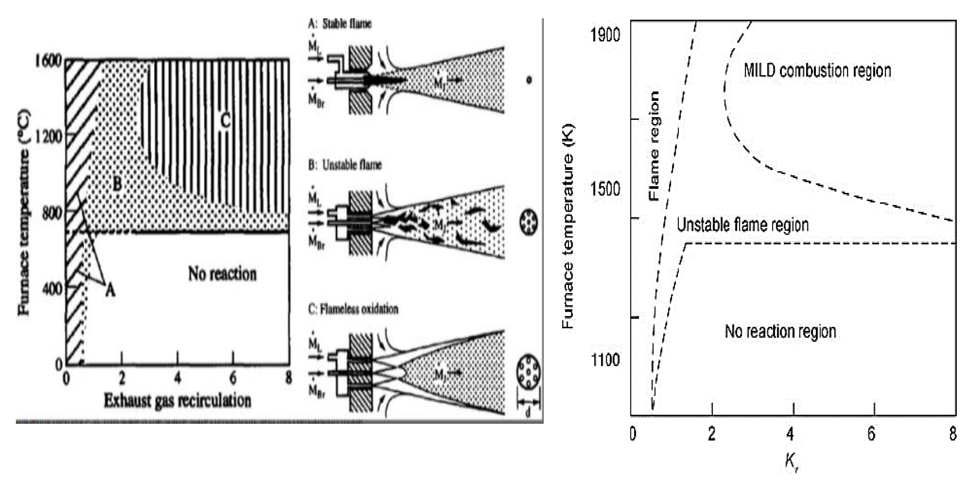
Figure 2.
The flame stability of NH3-CH4 combustion at different equivalence ratio as a function of ammonia fraction (XNH3) [12].
Figure 2.
The flame stability of NH3-CH4 combustion at different equivalence ratio as a function of ammonia fraction (XNH3) [12].
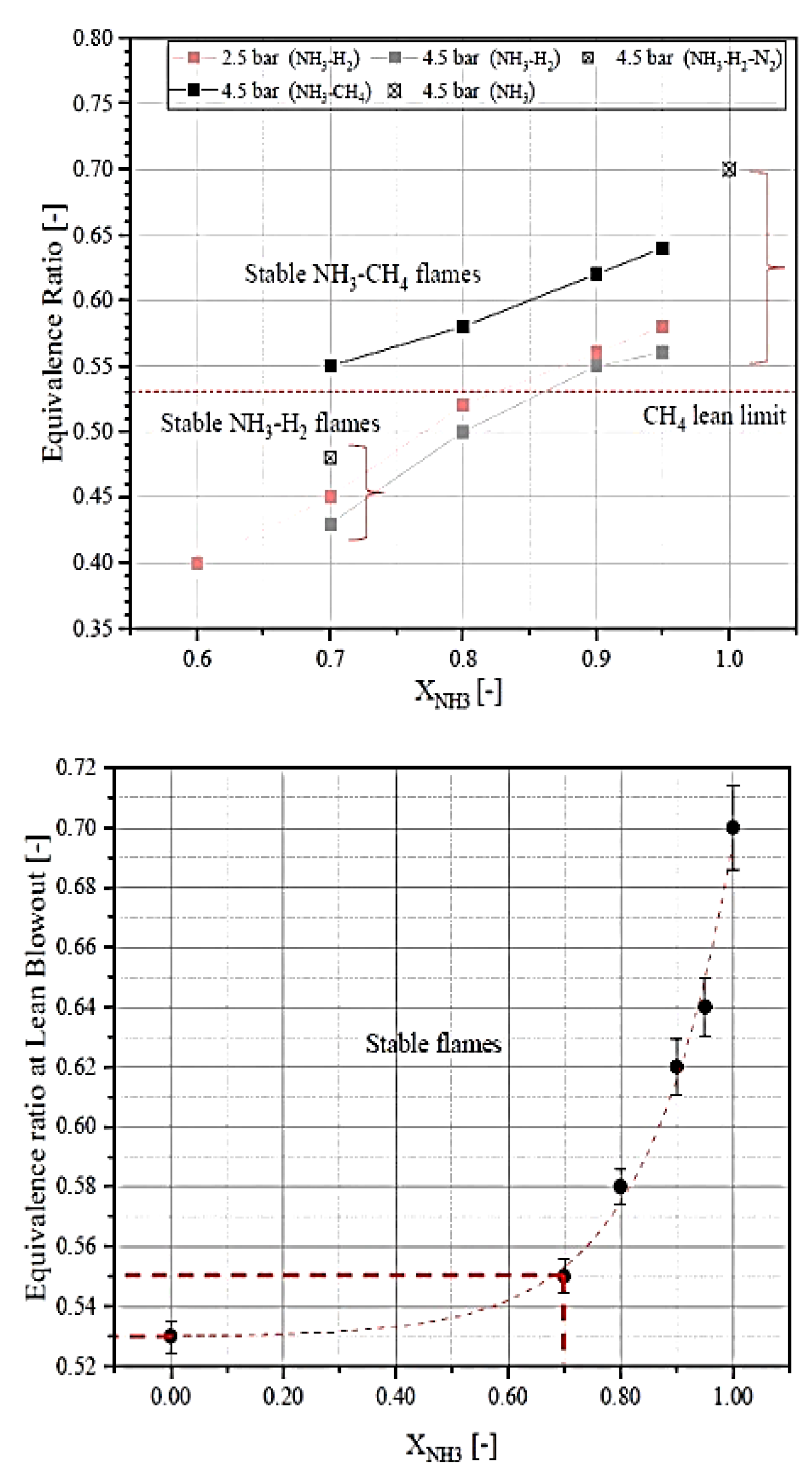
Figure 3.
The influences of initial pressure on flame propagation and equivalence ratio and experimental set up. Where Ld is the unburned gas Markstein length.
Figure 3.
The influences of initial pressure on flame propagation and equivalence ratio and experimental set up. Where Ld is the unburned gas Markstein length.
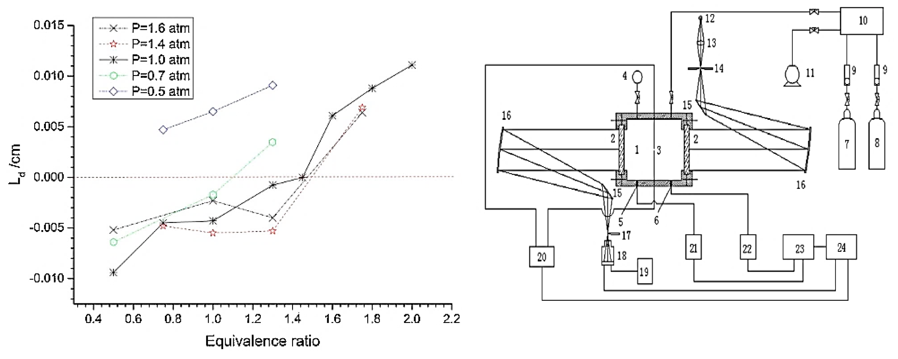
Figure 4.
Spectra of turbulent kinetic energy of premixed ammonia combustion blends of NH3/H2/N2/H2O – air. E10-H75-S09 represents the equivalence ratio 1, hydrogen content 0.75 and steam-to-air ratio 0.9 [21].
Figure 4.
Spectra of turbulent kinetic energy of premixed ammonia combustion blends of NH3/H2/N2/H2O – air. E10-H75-S09 represents the equivalence ratio 1, hydrogen content 0.75 and steam-to-air ratio 0.9 [21].
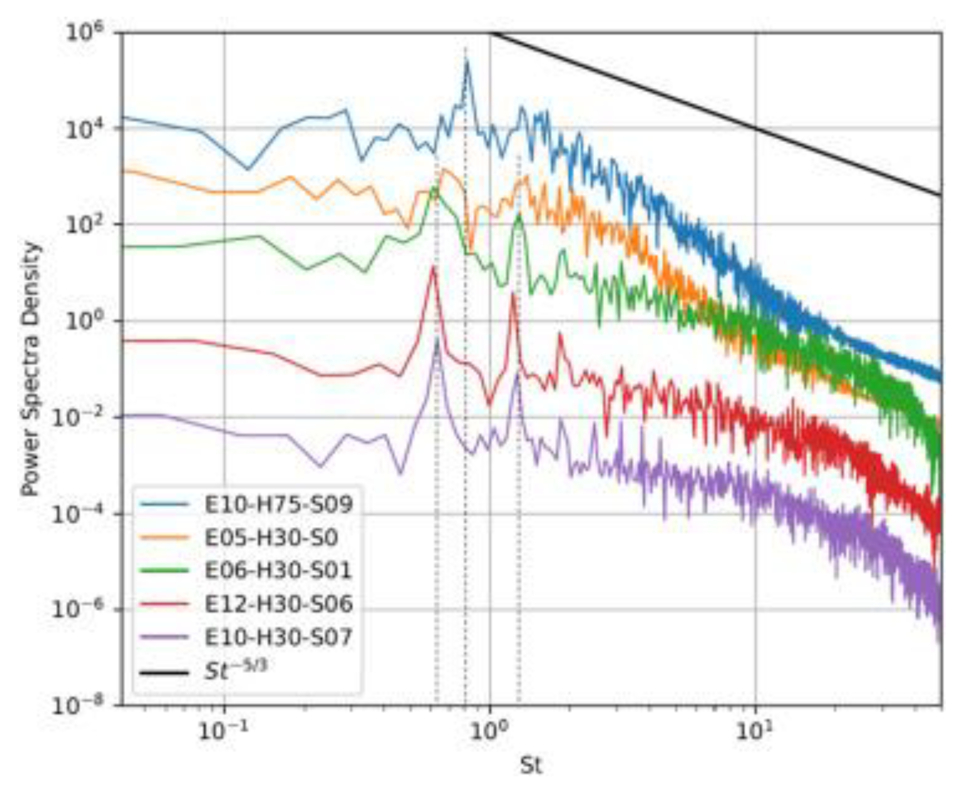
Figure 5.
Flame extinction, intensity curve and stability limits at various equivalence ratios, lip velocities and extinction time [23].
Figure 5.
Flame extinction, intensity curve and stability limits at various equivalence ratios, lip velocities and extinction time [23].
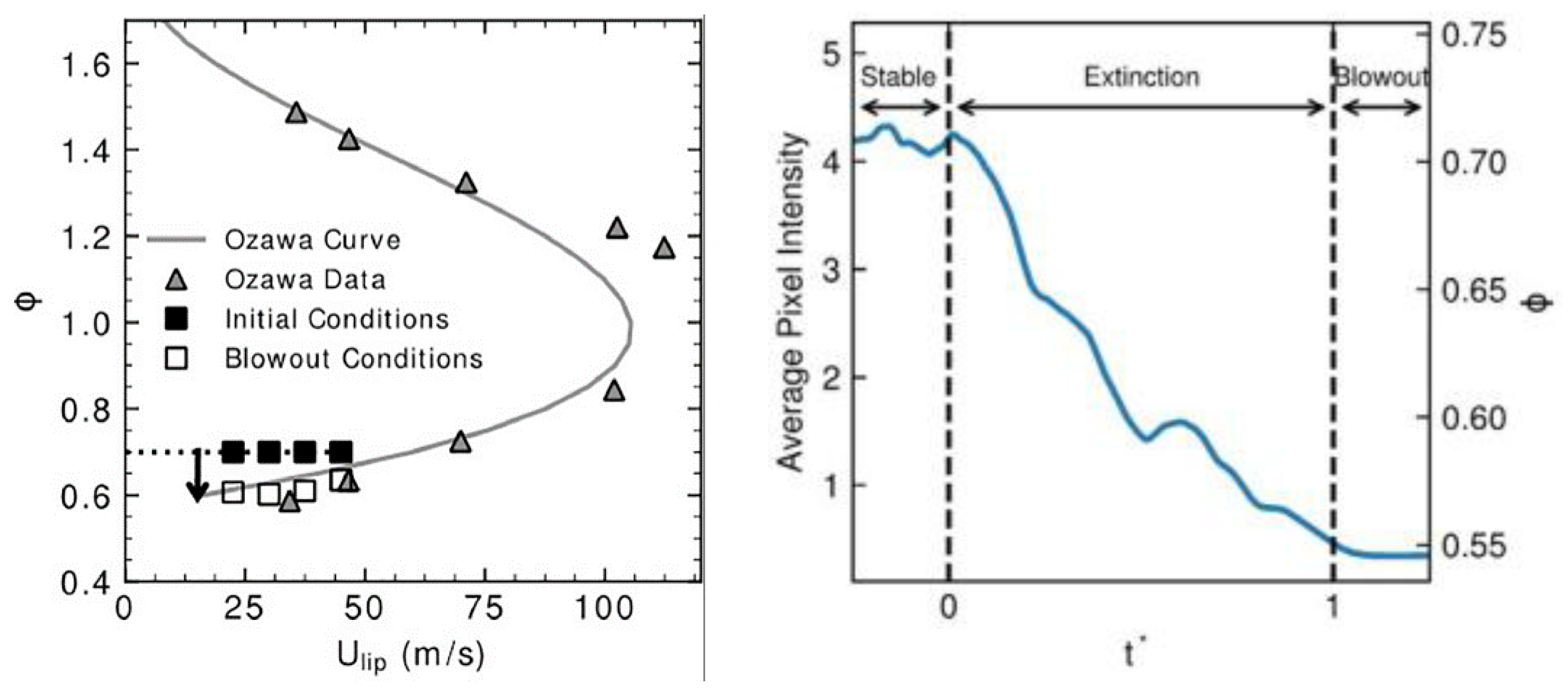
Figure 6.
The he Darrieus-Landau in terms to different order of k the wavenumber and ω the growth rate [25].
Figure 6.
The he Darrieus-Landau in terms to different order of k the wavenumber and ω the growth rate [25].
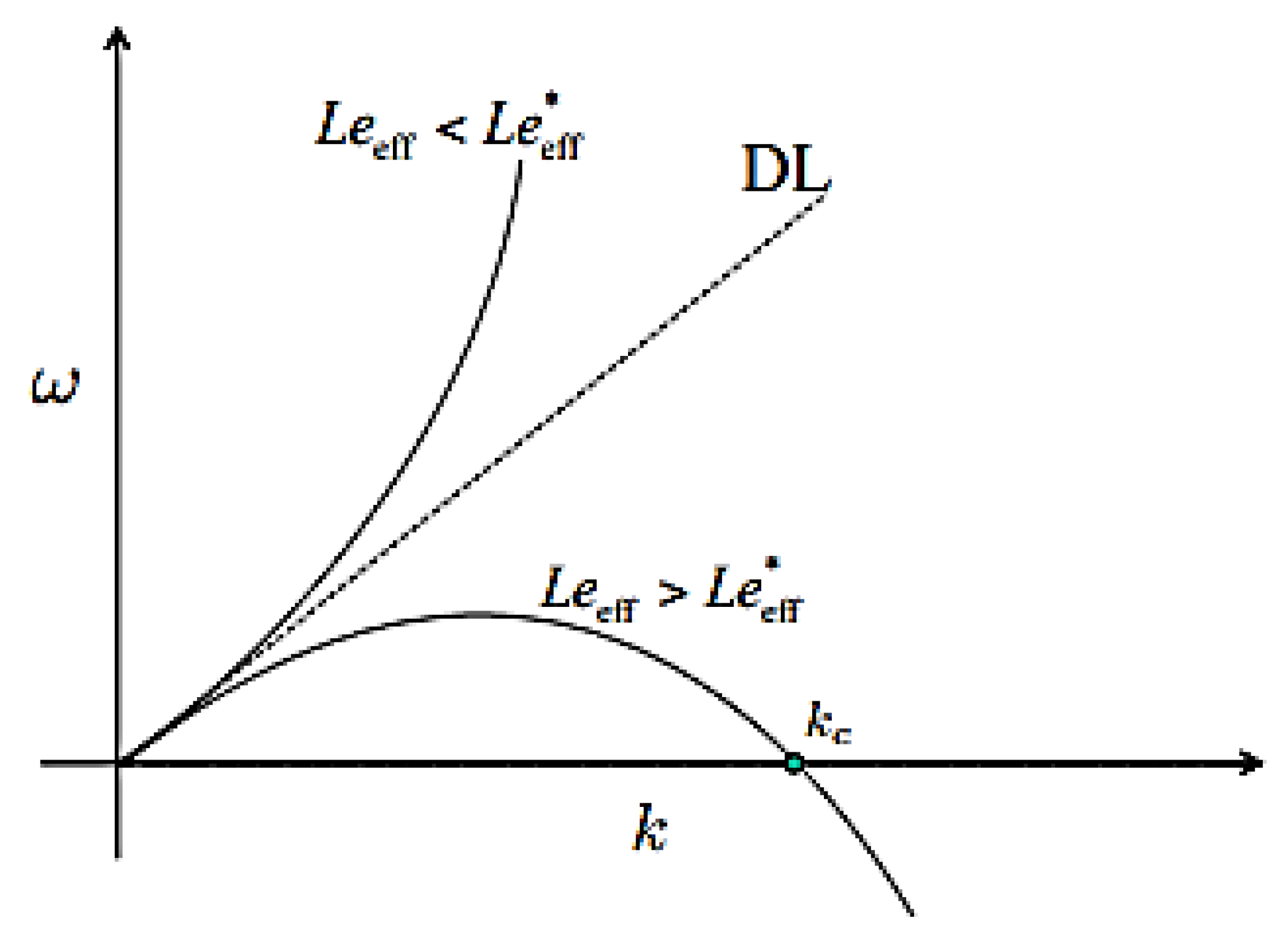
Figure 7.
A comparison of the temperature fluctuations for a flameless combustion compared to a classical diffusion flame in conventional combustion[21,45].

Figure 8.
Stability map of the premixed ammonia-air tubular flame in terms of equivalence ratios [42].
Figure 8.
Stability map of the premixed ammonia-air tubular flame in terms of equivalence ratios [42].
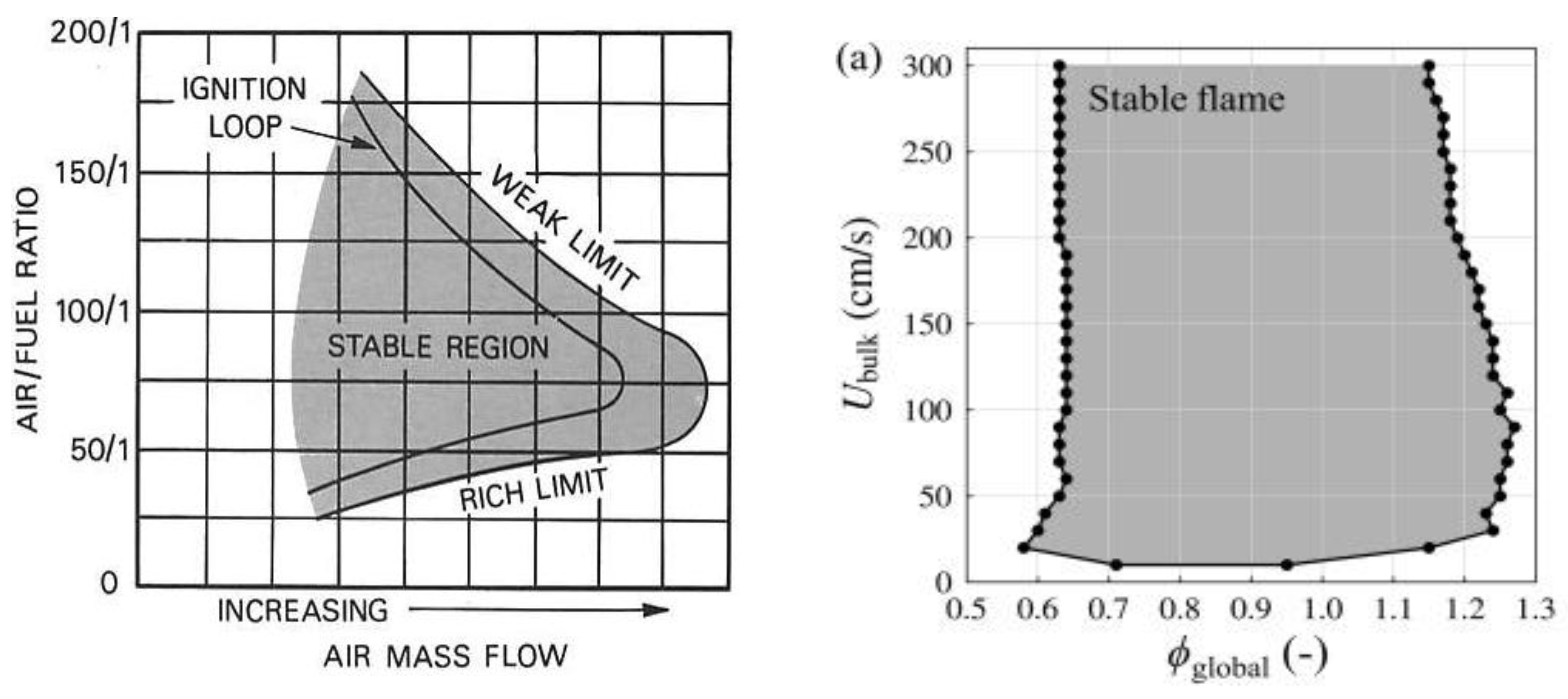
Figure 9.
The premixed ammonia-air tubular flame and NO emission, in multistage staging tangential fuel injection combustor [49].
Figure 9.
The premixed ammonia-air tubular flame and NO emission, in multistage staging tangential fuel injection combustor [49].
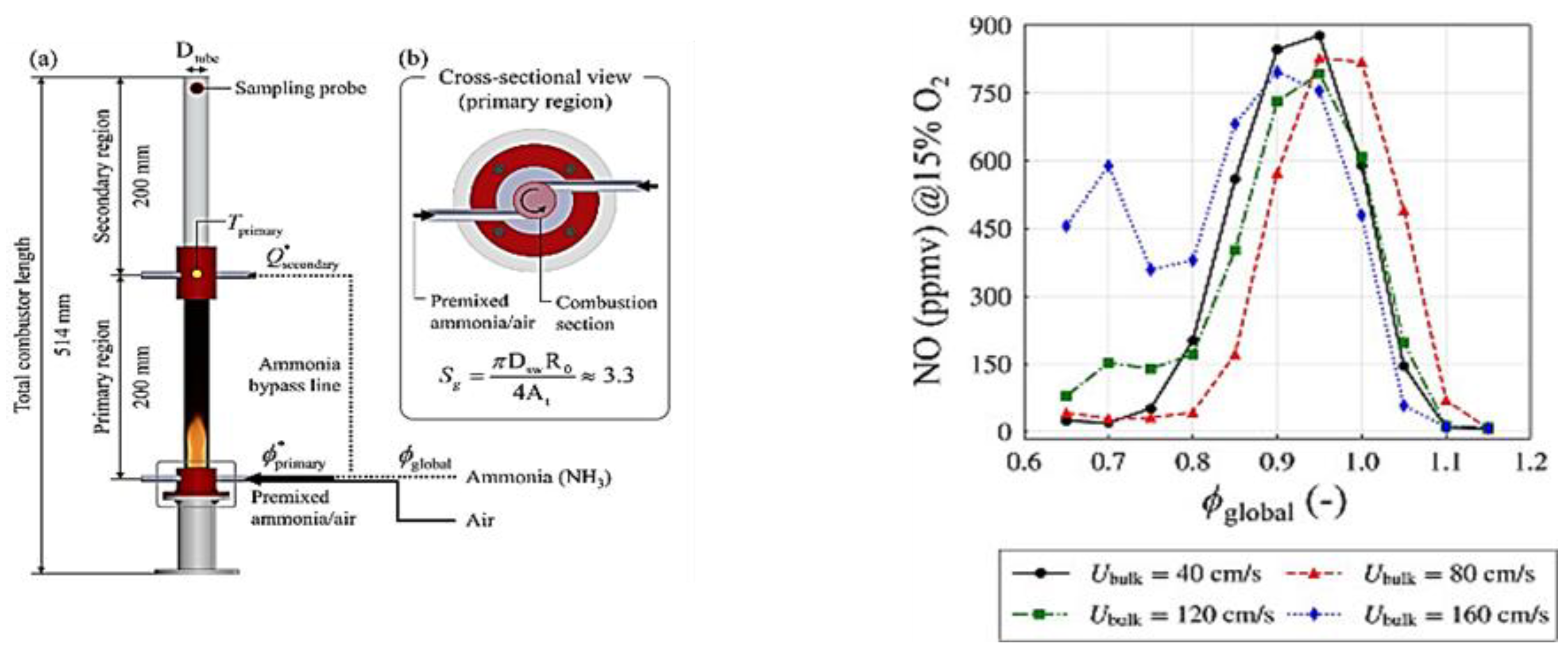
Figure 10.
Stability limits of premixed NH3/air flames at various equivalence ratio (0.8-1.4) at 300 K and 0.1 MPa. The dotted lines represent heat values [50].
Figure 10.
Stability limits of premixed NH3/air flames at various equivalence ratio (0.8-1.4) at 300 K and 0.1 MPa. The dotted lines represent heat values [50].
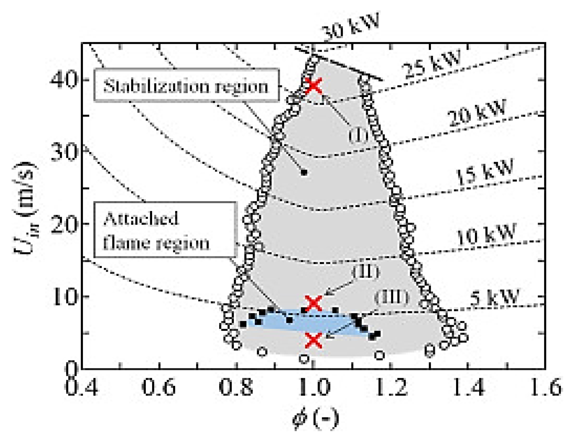
Figure 11.
The stability limit as a function of the exit velocities corresponding to equivalence ratio [52].
Figure 11.
The stability limit as a function of the exit velocities corresponding to equivalence ratio [52].
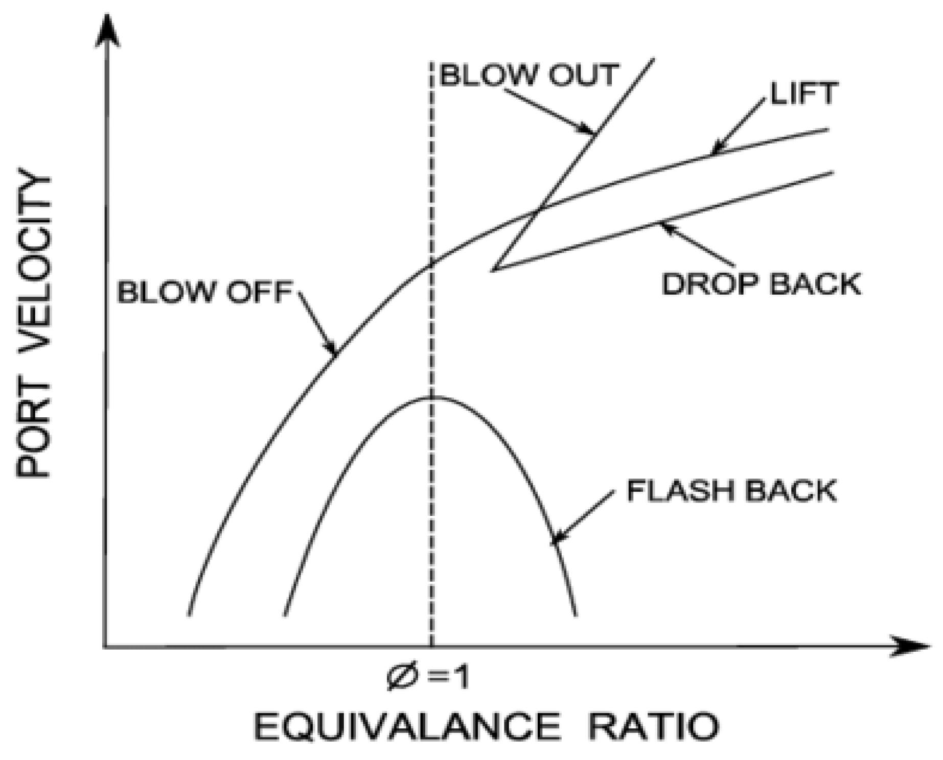
Figure 12.
Variation of combustion pressure (MPa) over time in premixed ammonia-oxygen flames at different equivalence ratios (ϕ)[49].
Figure 12.
Variation of combustion pressure (MPa) over time in premixed ammonia-oxygen flames at different equivalence ratios (ϕ)[49].
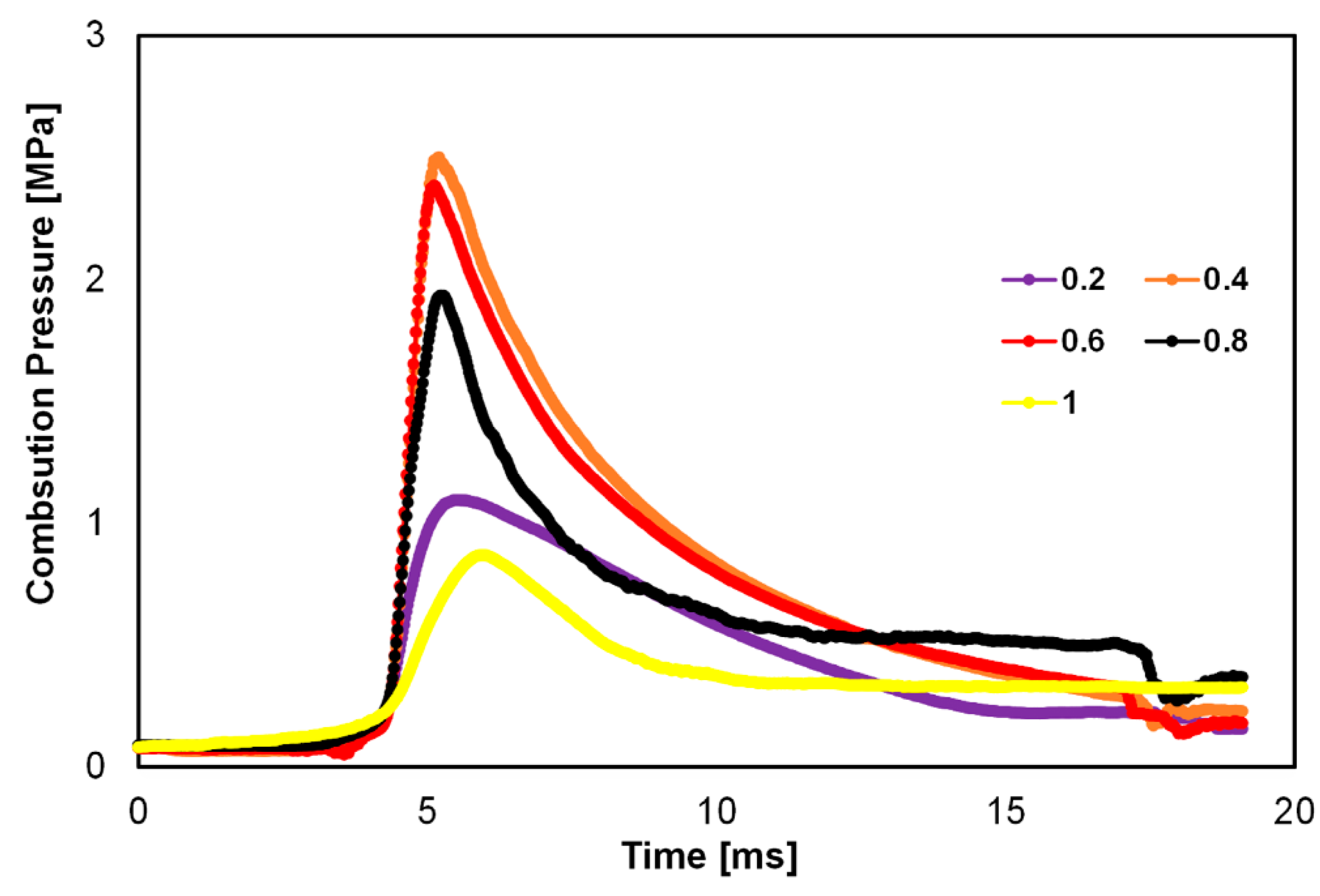
Figure 13.
Comparison of premixed ammonia air laminar flame flow velocity at boundary layer flashback, 293 K and 101 kPa [56].
Figure 13.
Comparison of premixed ammonia air laminar flame flow velocity at boundary layer flashback, 293 K and 101 kPa [56].
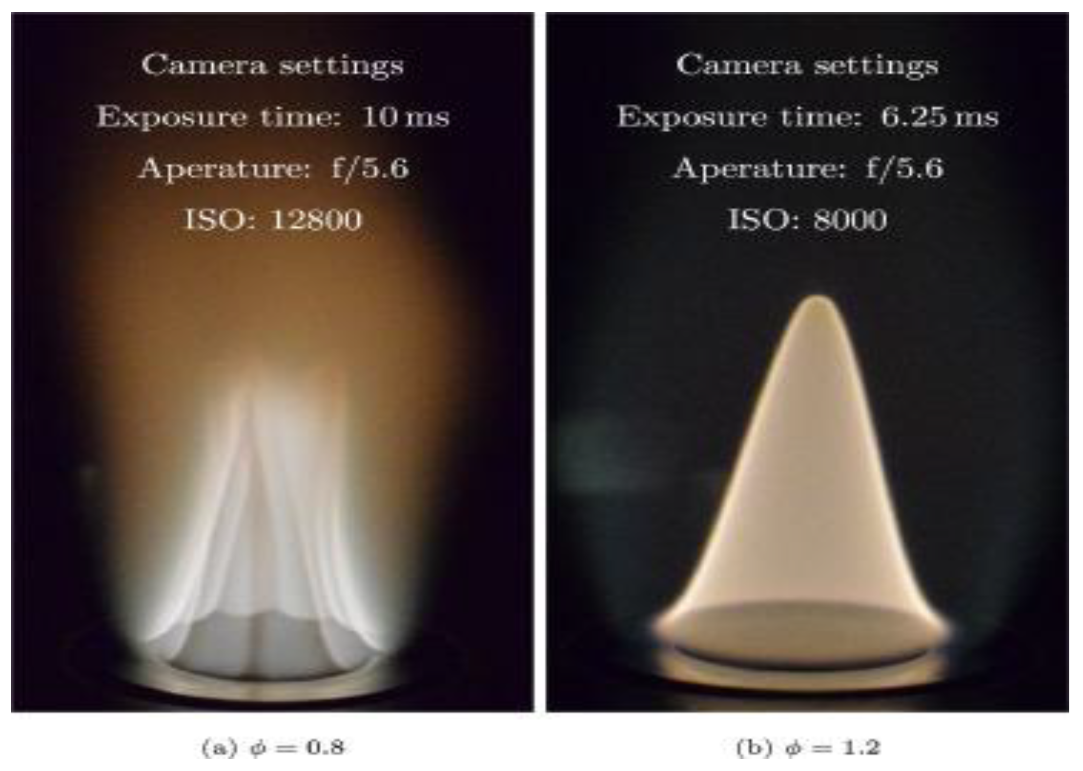
Figure 14.
The stability diagram of NH3/H2/air flames based on equivalence ratio corresponded to molar fraction of ammonia. The flashback conditions are indicated by red triangles [55
Figure 14.
The stability diagram of NH3/H2/air flames based on equivalence ratio corresponded to molar fraction of ammonia. The flashback conditions are indicated by red triangles [55
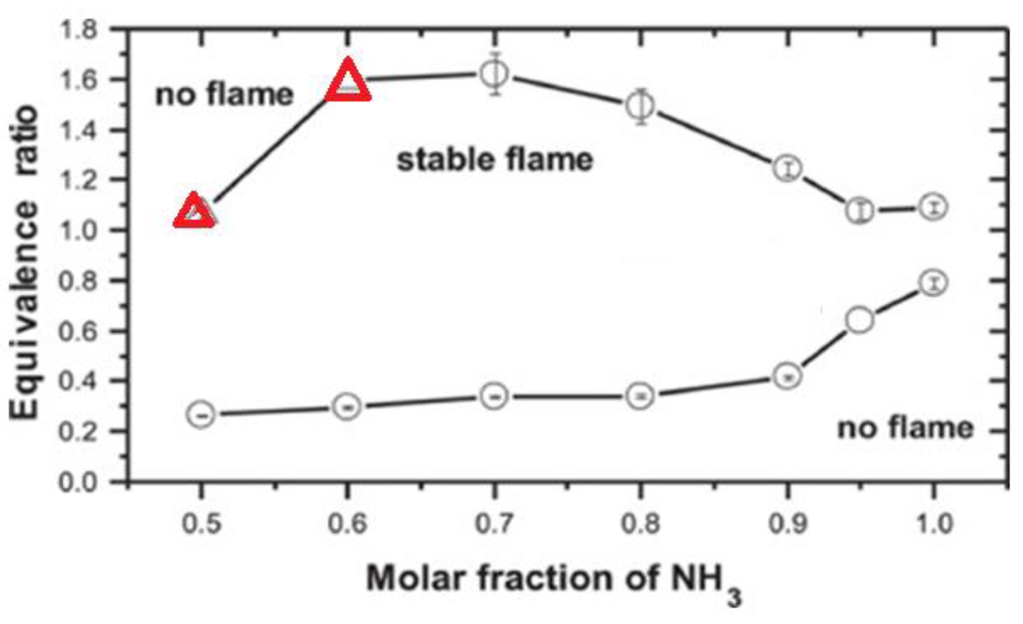
Figure 15.
The laminar burning velocity in terms of equivalence ratio [58].
Figure 15.
The laminar burning velocity in terms of equivalence ratio [58].
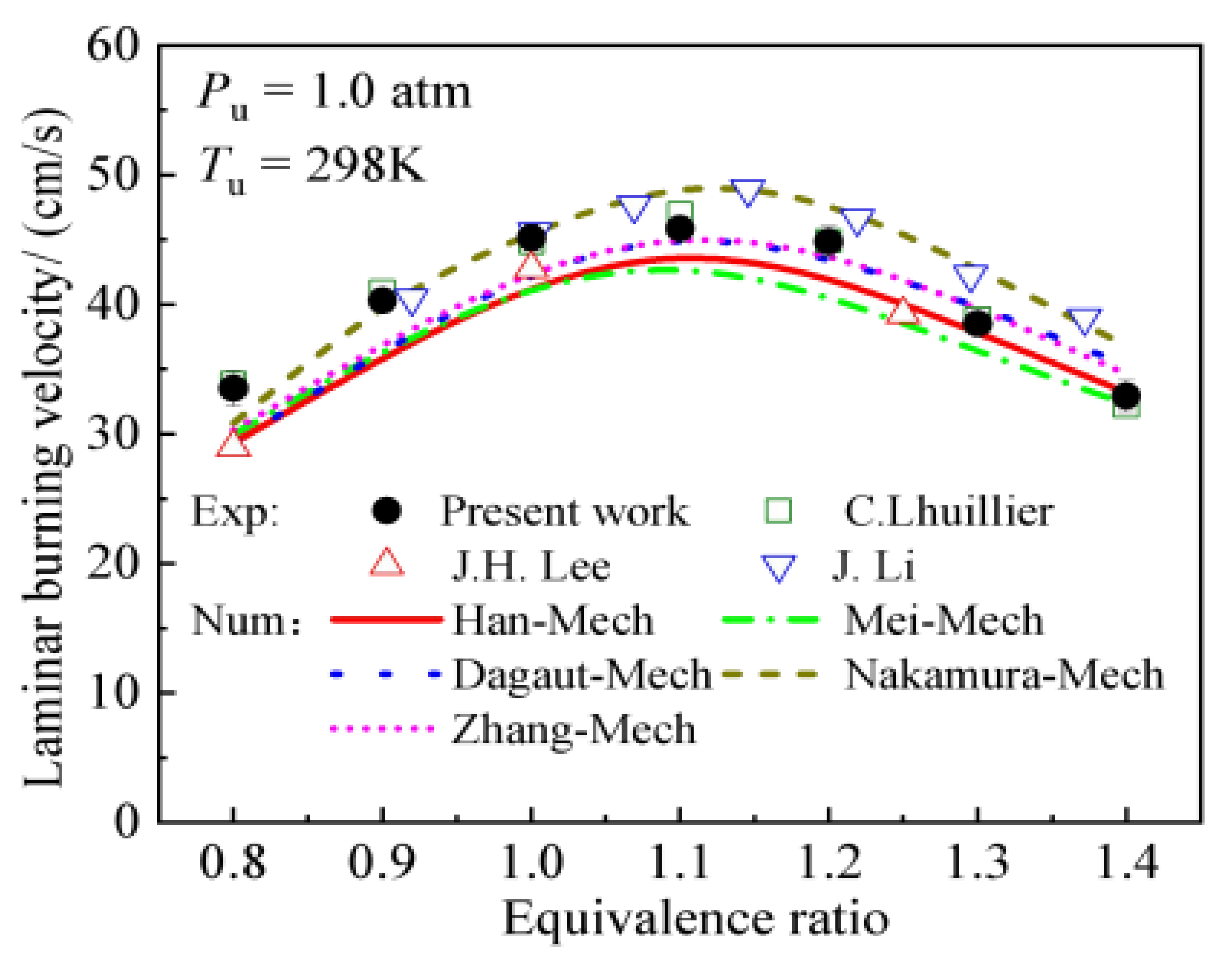
Figure 16.
The comparison of burner flow velocity of ammonia air and hydrogen mixtures in swirl premix ammonia–air burners at different equivalence ratios (a) the boundary-layer flashback (BLF) and (b) the laminar burning velocity at 483 K, 101 kPa conditions [56].
Figure 16.
The comparison of burner flow velocity of ammonia air and hydrogen mixtures in swirl premix ammonia–air burners at different equivalence ratios (a) the boundary-layer flashback (BLF) and (b) the laminar burning velocity at 483 K, 101 kPa conditions [56].
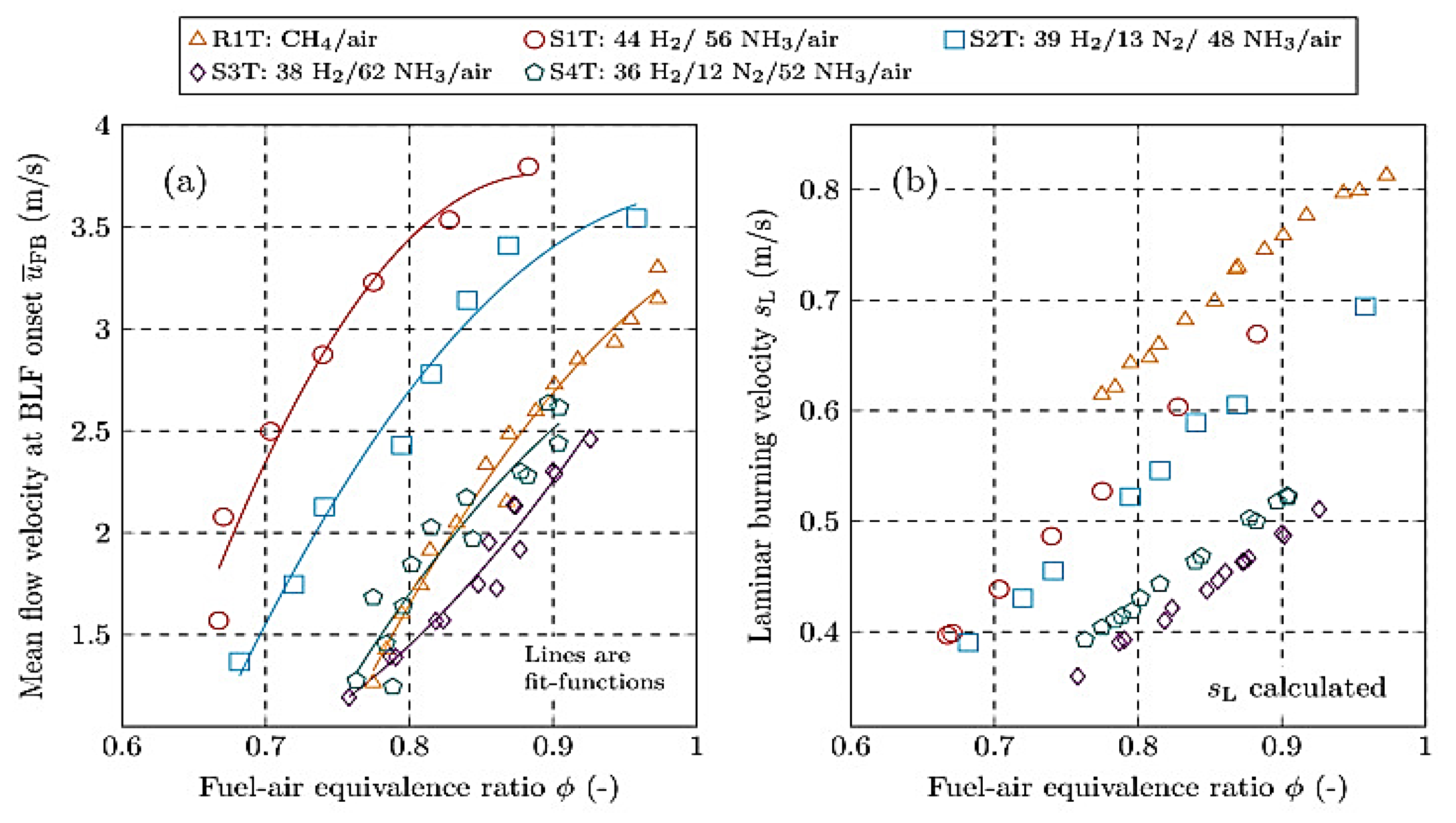
Figure 17.
The flammability limits of premixed and diffusion flames based on concentrations of fuel vapor /air mixture at different temperature [59].
Figure 17.
The flammability limits of premixed and diffusion flames based on concentrations of fuel vapor /air mixture at different temperature [59].
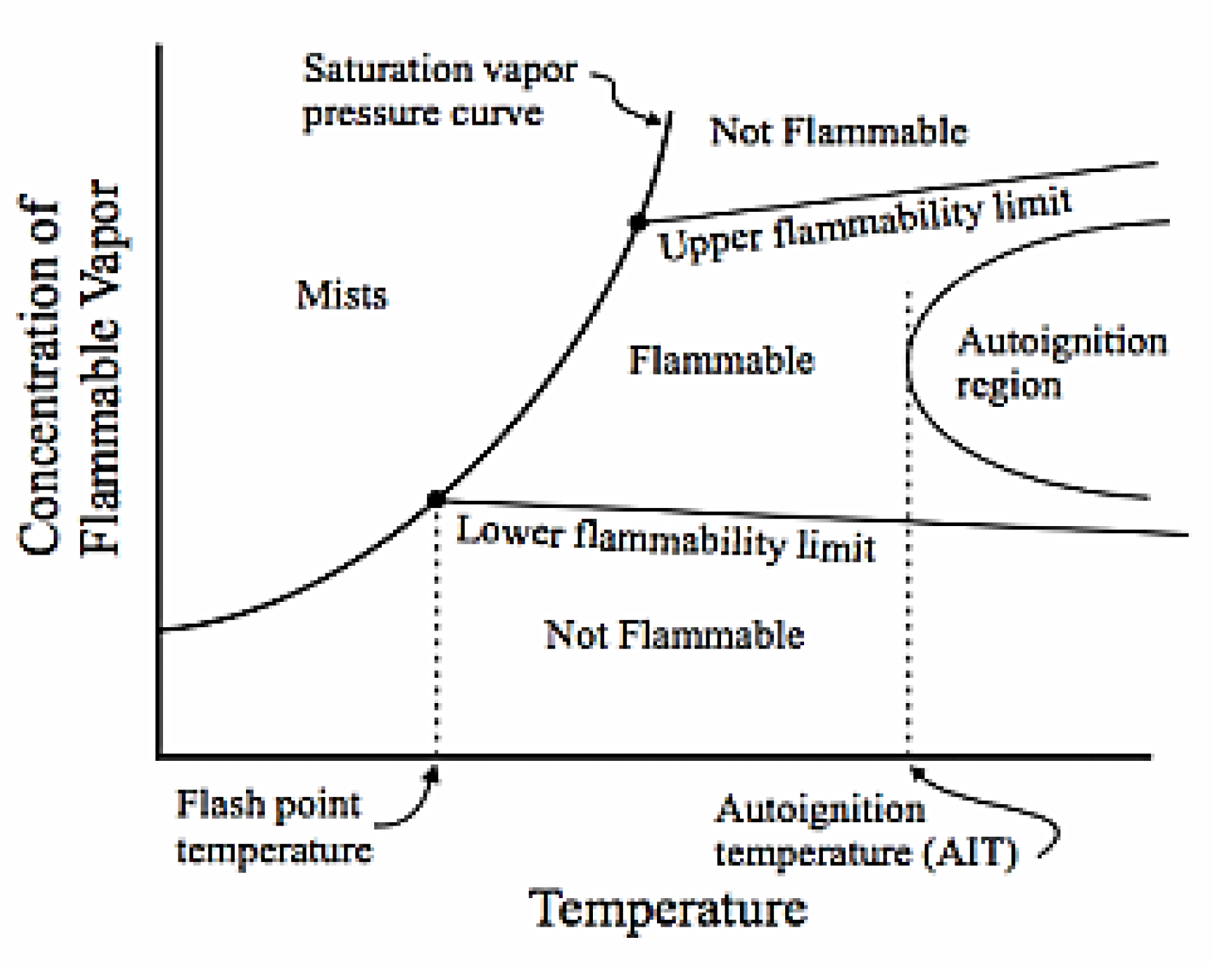
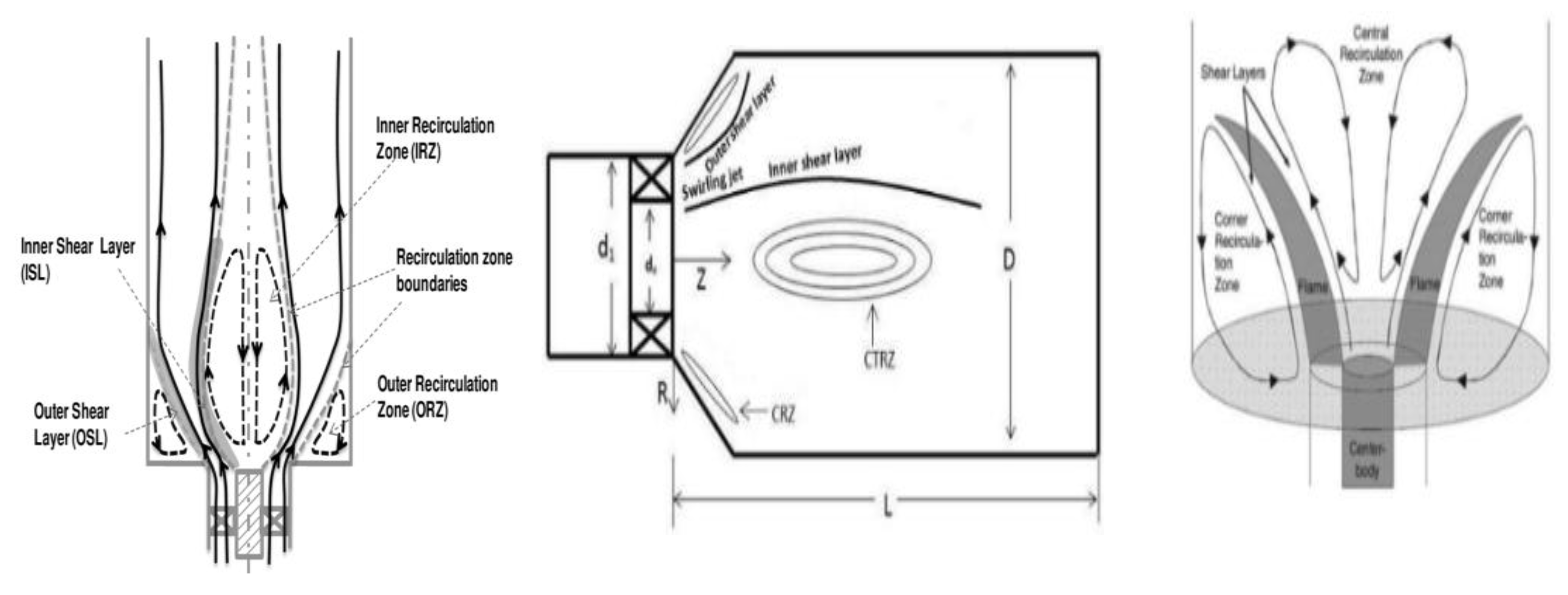
Figure 19.
Comparison of stability limits of non-premixed flames with swirl stabilized quarl and non-quarl. The Ua is air and Uf is fuel flow velocity [66].
Figure 19.
Comparison of stability limits of non-premixed flames with swirl stabilized quarl and non-quarl. The Ua is air and Uf is fuel flow velocity [66].
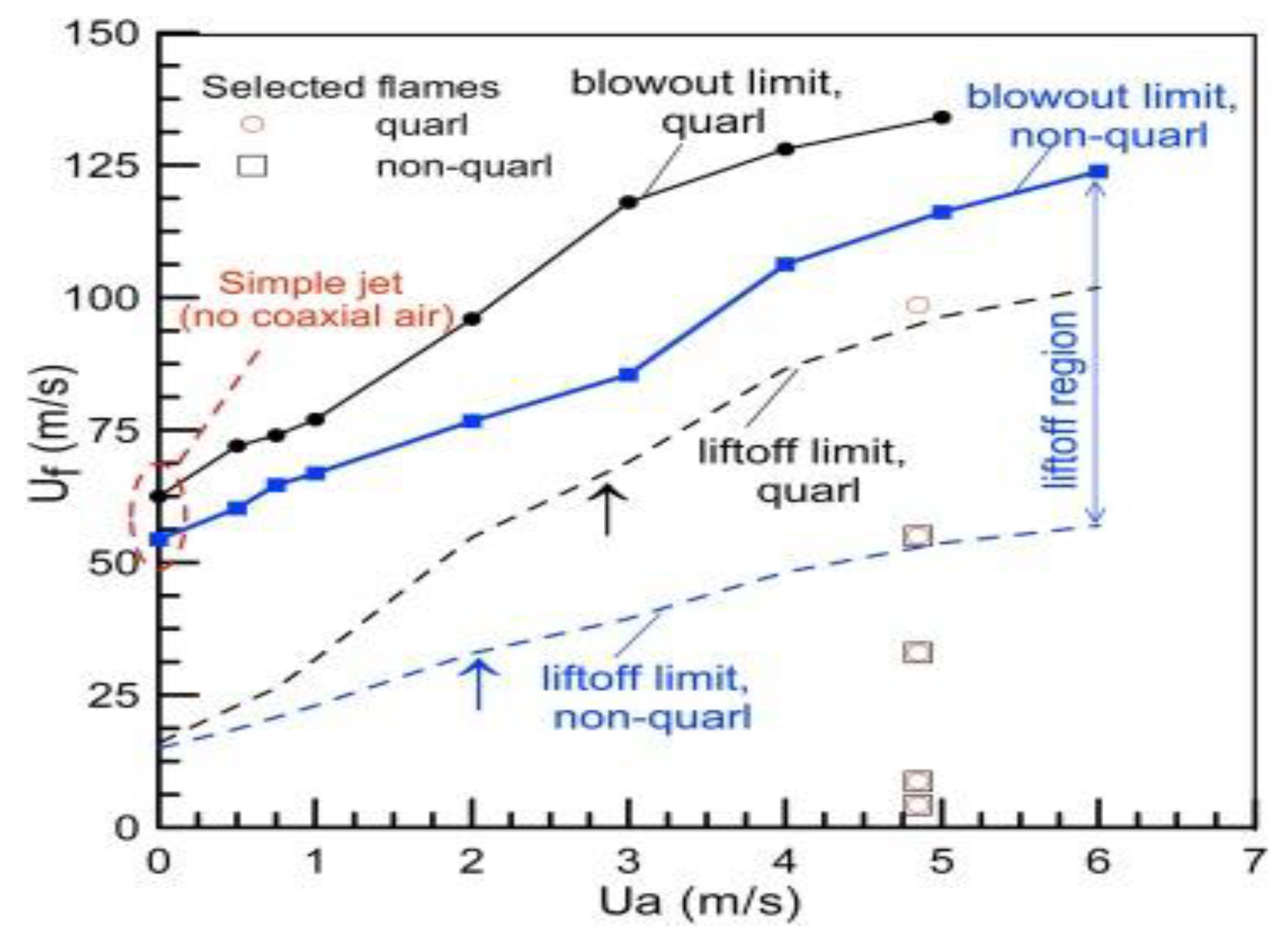
Figure 20.
Comparison stability limits of ammonia- hydrogen with ammonia- methane flames [12].
Figure 20.
Comparison stability limits of ammonia- hydrogen with ammonia- methane flames [12].
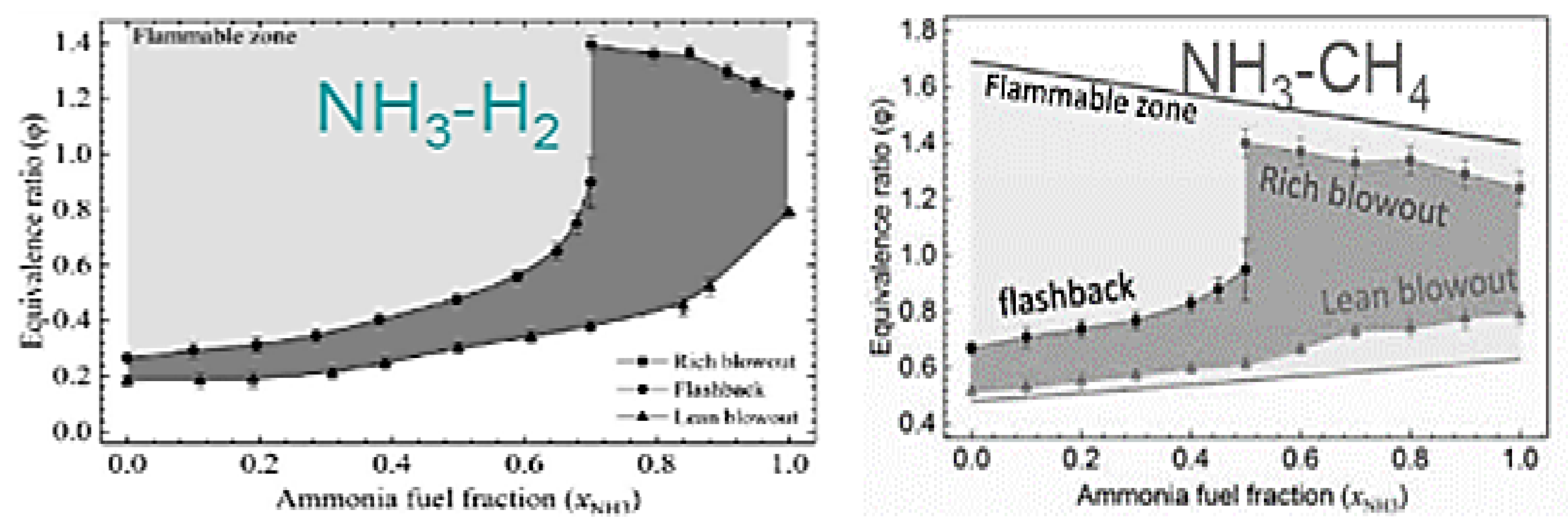
Figure 21.
Blowout based on inverse of Damkohler number [68].
Figure 21.
Blowout based on inverse of Damkohler number [68].
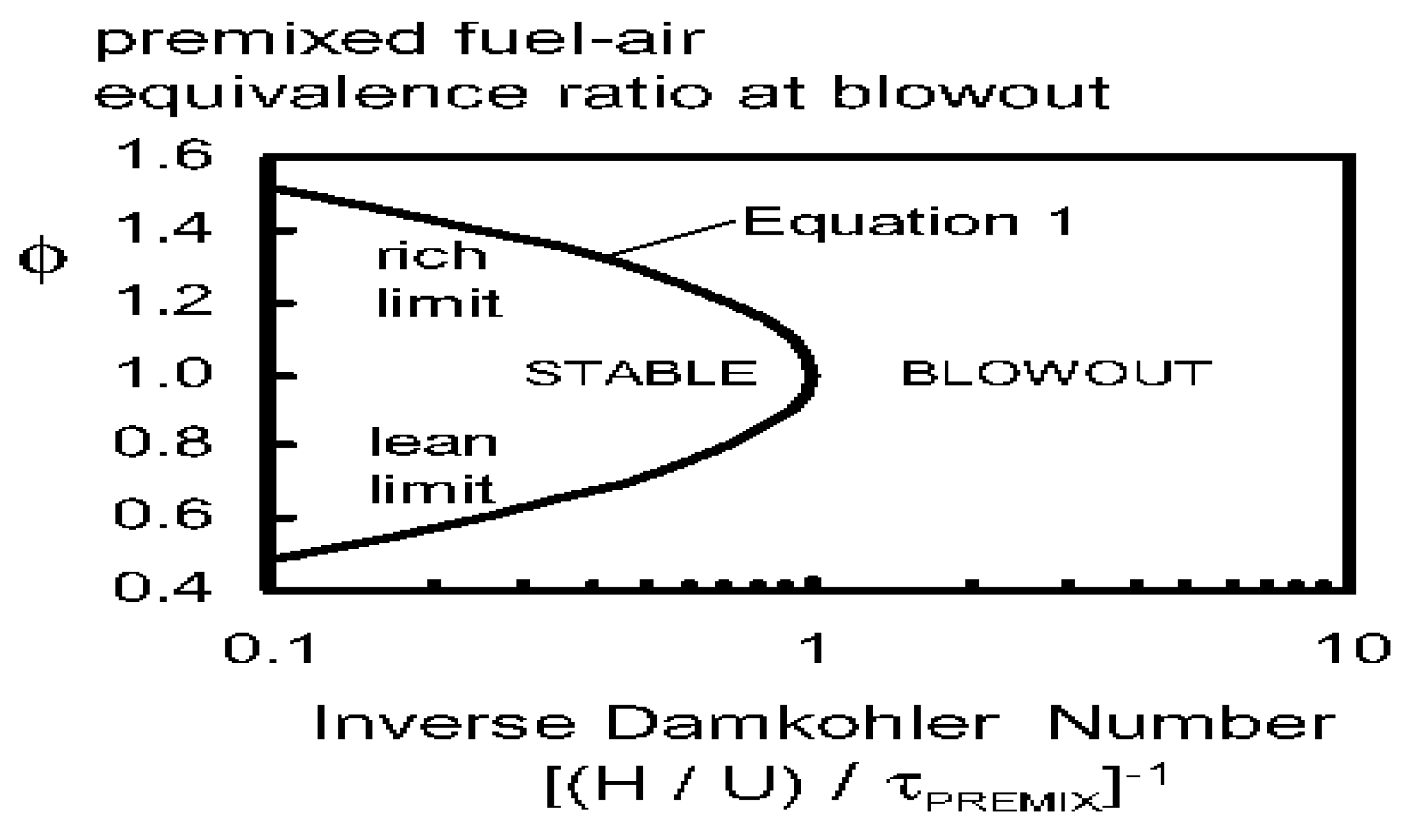
Figure 22.
The stability diagram of laminar counterflow diffusion flames obtained by varying the air (Ua=1 the blue line) and fuel velocities (red line Uf=1) [69].
Figure 22.
The stability diagram of laminar counterflow diffusion flames obtained by varying the air (Ua=1 the blue line) and fuel velocities (red line Uf=1) [69].
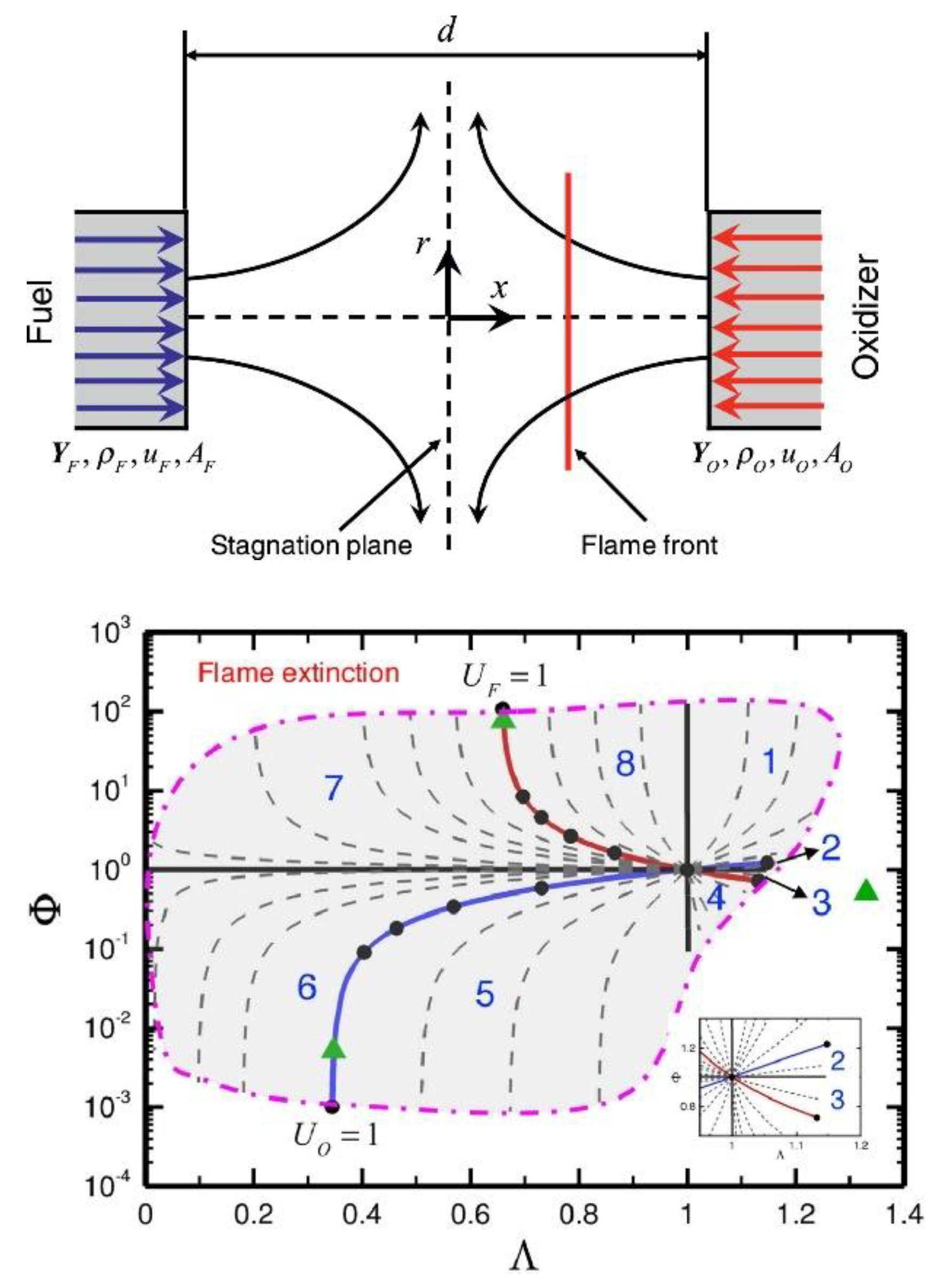
Figure 23.
The extinction stretches rate (εext) of ammonia air premixed flame for various equivalence ratio at atmospheric pressure [47].
Figure 23.
The extinction stretches rate (εext) of ammonia air premixed flame for various equivalence ratio at atmospheric pressure [47].
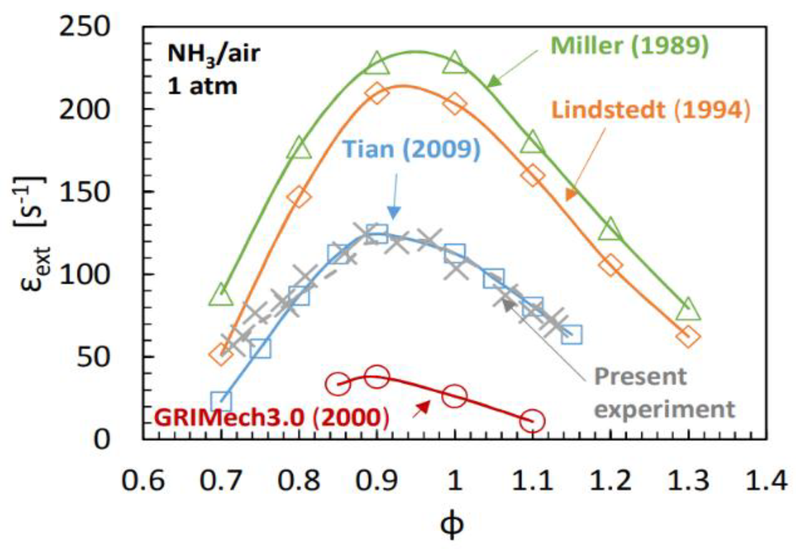
Figure 24.
The flame extinction in terms of Karlovitz number at the critical value of Peclet number (Pe ) [72].
Figure 24.
The flame extinction in terms of Karlovitz number at the critical value of Peclet number (Pe ) [72].
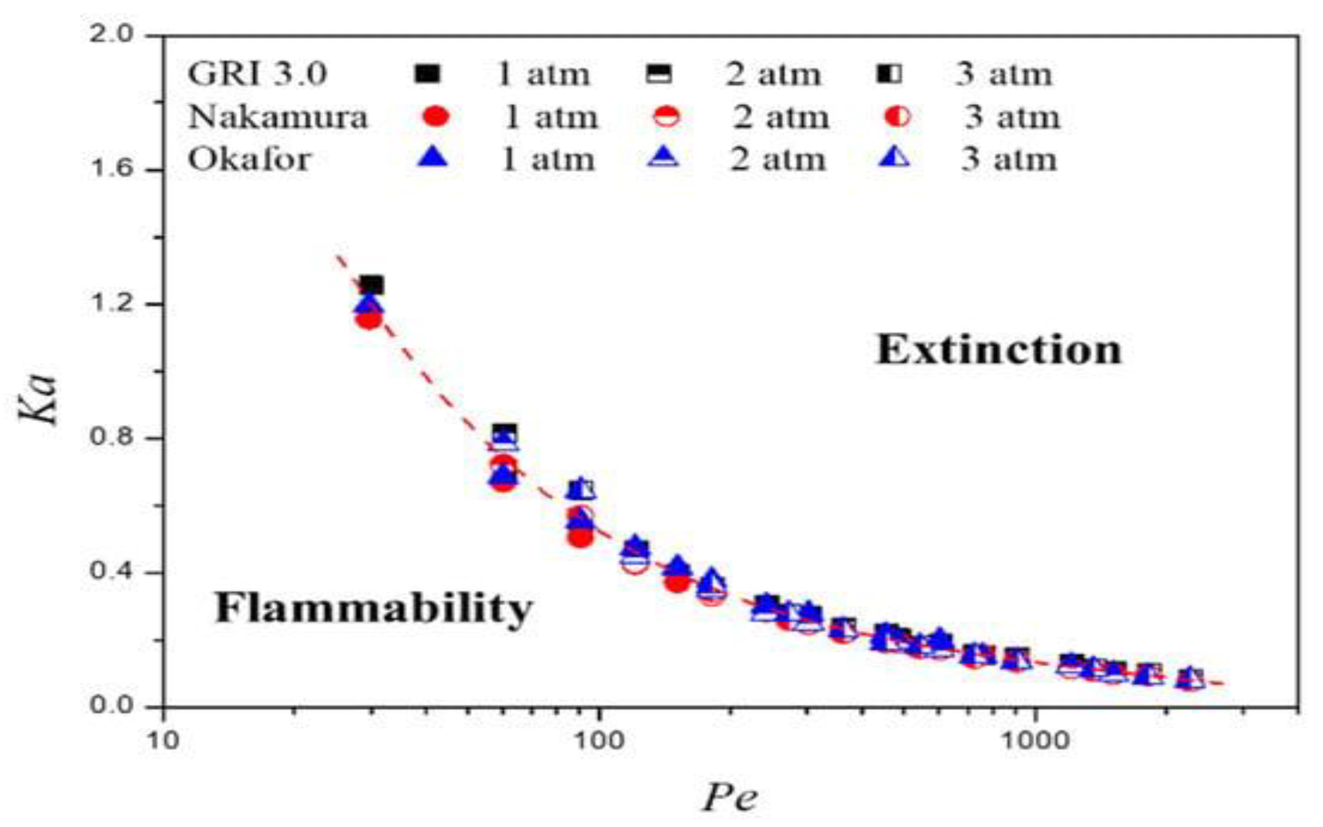
Figure 25.
Heat release change of the lean premixed flame of NH3 -CH4 - air in a model gas turbine with different phase angles. The pressure change is measured by a dynamic pressure sensor (#5p) installed at the fuel-air swirl injector nozzle. [75].
Figure 25.
Heat release change of the lean premixed flame of NH3 -CH4 - air in a model gas turbine with different phase angles. The pressure change is measured by a dynamic pressure sensor (#5p) installed at the fuel-air swirl injector nozzle. [75].
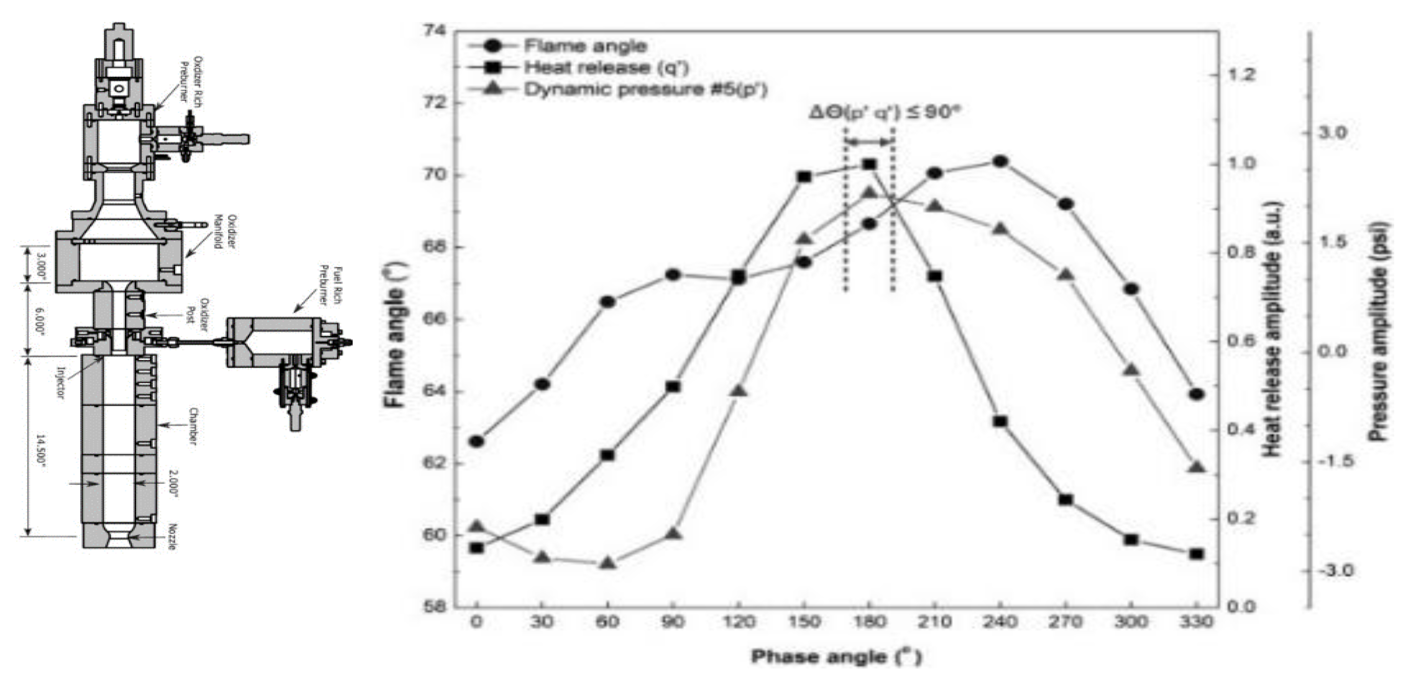
Figure 26.
Diagram and flame regime at various swirl numbers of a low-swirl vane burner and air flow rates [61].
Figure 26.
Diagram and flame regime at various swirl numbers of a low-swirl vane burner and air flow rates [61].
Figure 27.
Laminar burning velocity of NH3 equivalence ratio at various oxygen level.
Figure 28.
A reduction in stability limits and NO emission of a two-stage NH3/air premixed flames influenced by secondary air injection at various equivalence ratios (ϕpri) and 0.5 MPa[45].
Figure 28.
A reduction in stability limits and NO emission of a two-stage NH3/air premixed flames influenced by secondary air injection at various equivalence ratios (ϕpri) and 0.5 MPa[45].
Figure 29.
The swirling ammonia-air combustion in terms of (a)various flow conditions, (b) plasma-assisted swirl-stabilized burner [87].
Figure 29.
The swirling ammonia-air combustion in terms of (a)various flow conditions, (b) plasma-assisted swirl-stabilized burner [87].
Figure 30.
(a) diagram of flue gas recirculation (a,b) in flameless combustion [69], (b) the effect of transitioning from a swirl flame to the flameless method on NOx reduction [90]..
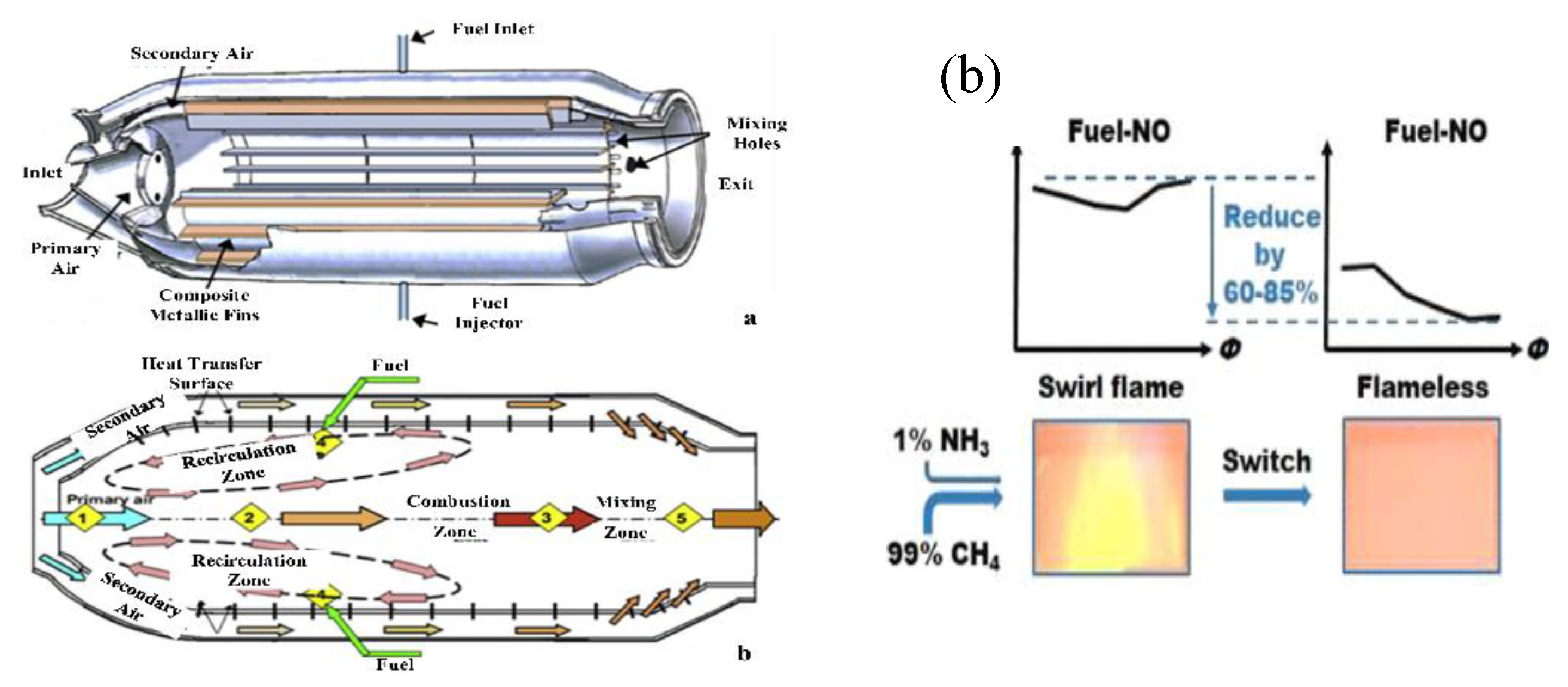
Figure 31.
NOx emissions of a swirl flame(a) and a flameless combustion(b) at various equivalence ratio [90].
Figure 31.
NOx emissions of a swirl flame(a) and a flameless combustion(b) at various equivalence ratio [90].
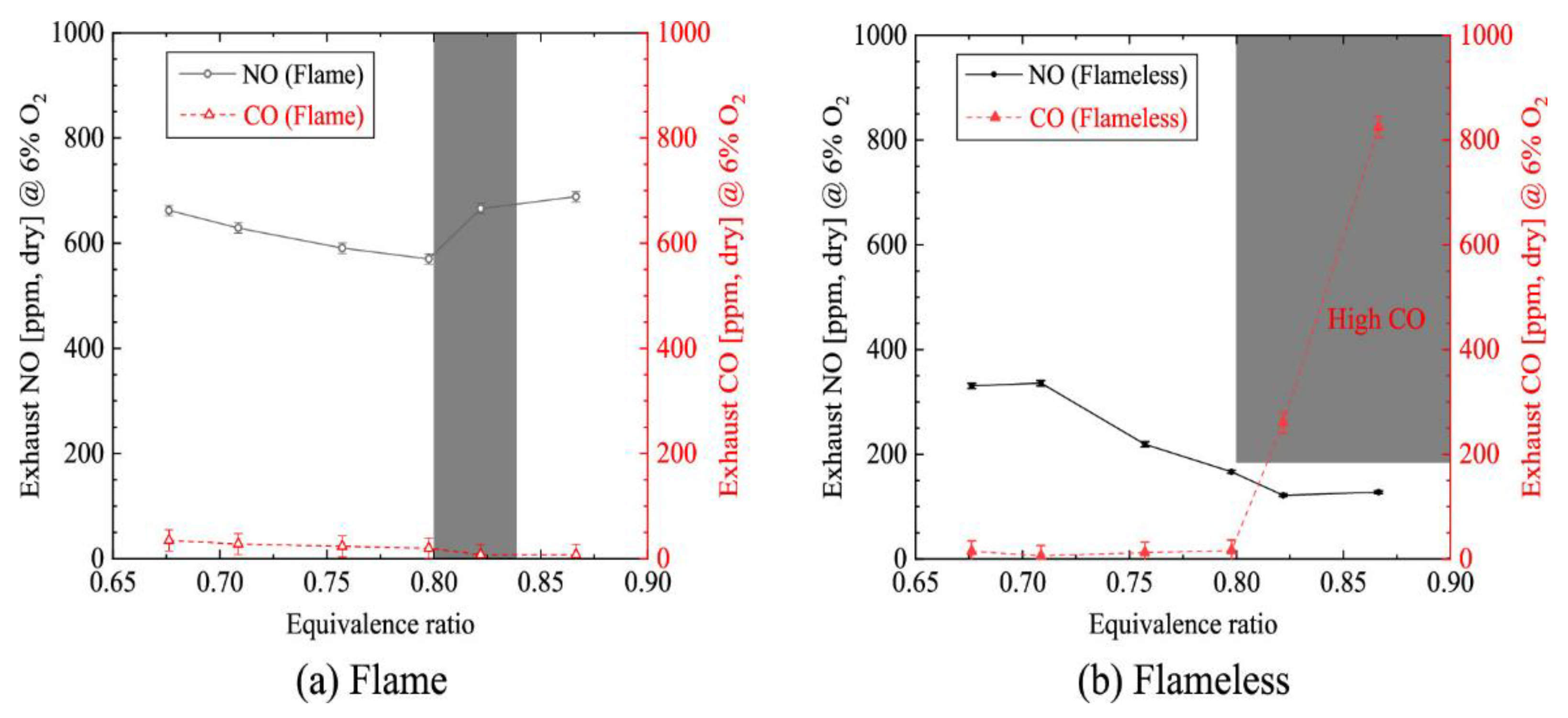
Figure 32.
The NOx emission over time at various O2 concentration at temperatureof (a)1000 °C and (b) 800 °C during flameless combustion [3,88].
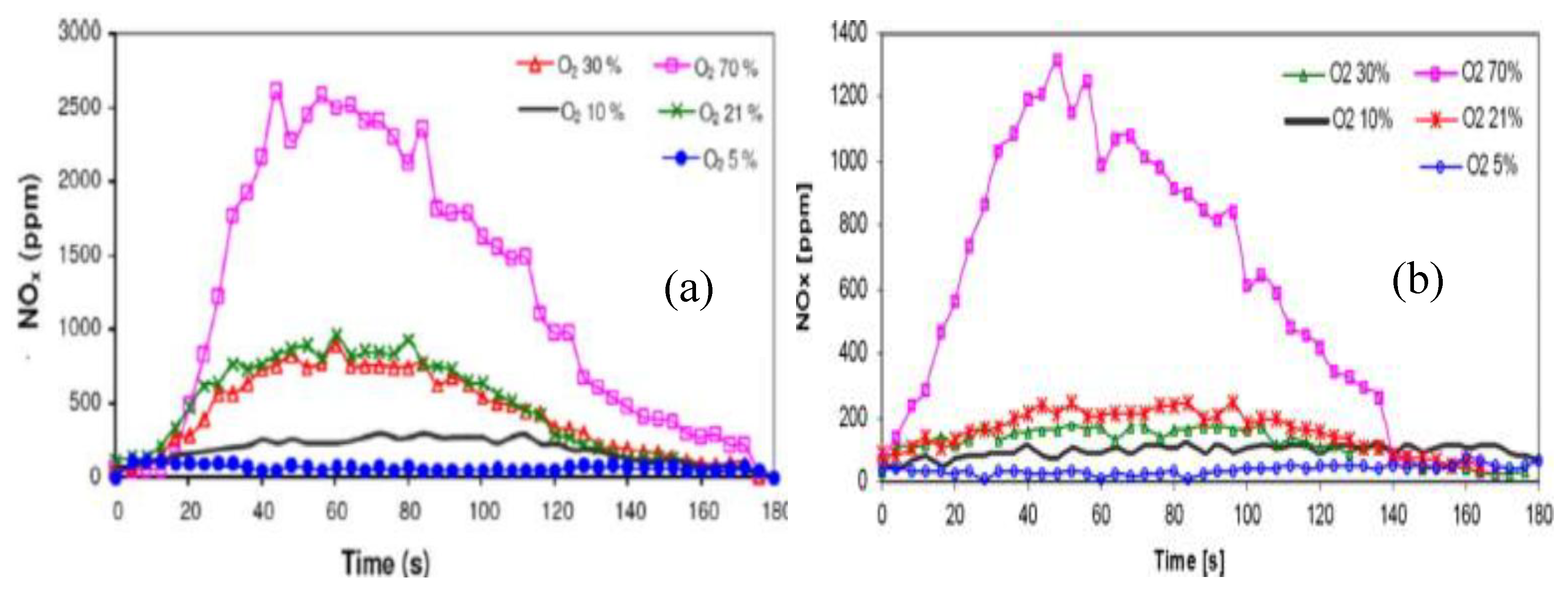
Figure 33.
Emission analysis apparatus for exhaust gas and NOx concentration (a)of the NH3–air combustion and the SCR (b)in gas turbine power generation system(c) [81].
Figure 33.
Emission analysis apparatus for exhaust gas and NOx concentration (a)of the NH3–air combustion and the SCR (b)in gas turbine power generation system(c) [81].
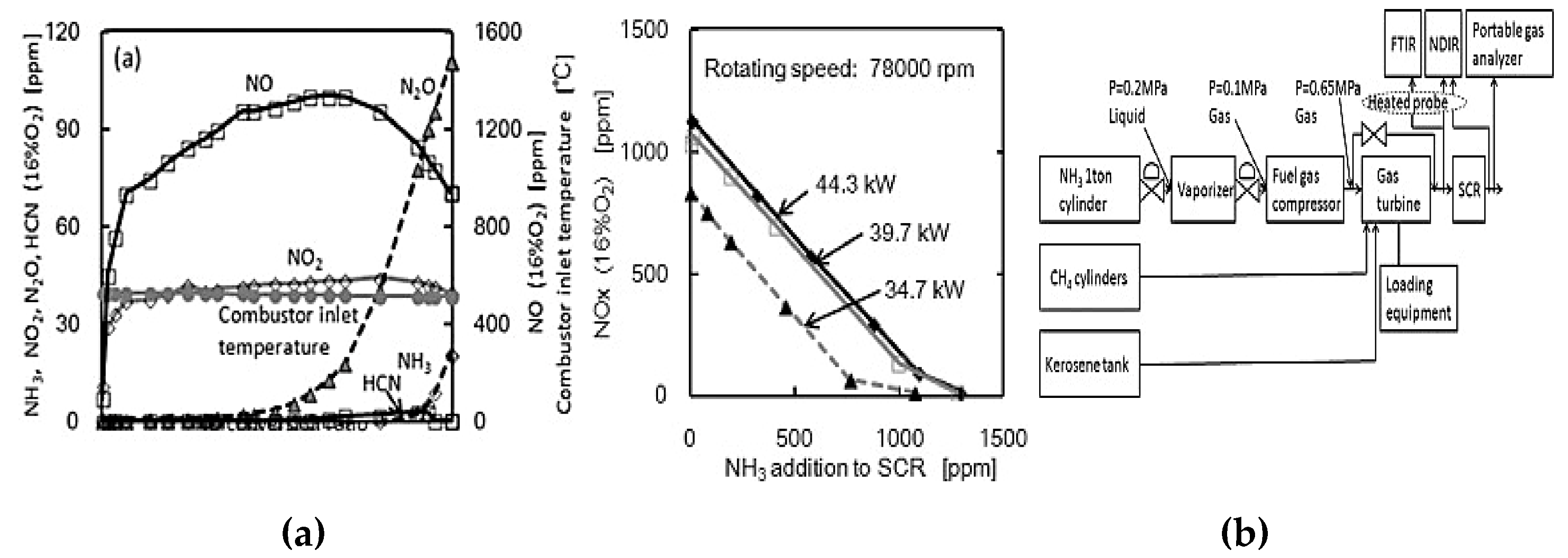
Figure 34.
The lean NOx trap with adsorption under lean and conditions[72].
Figure 34.
The lean NOx trap with adsorption under lean and conditions[72].
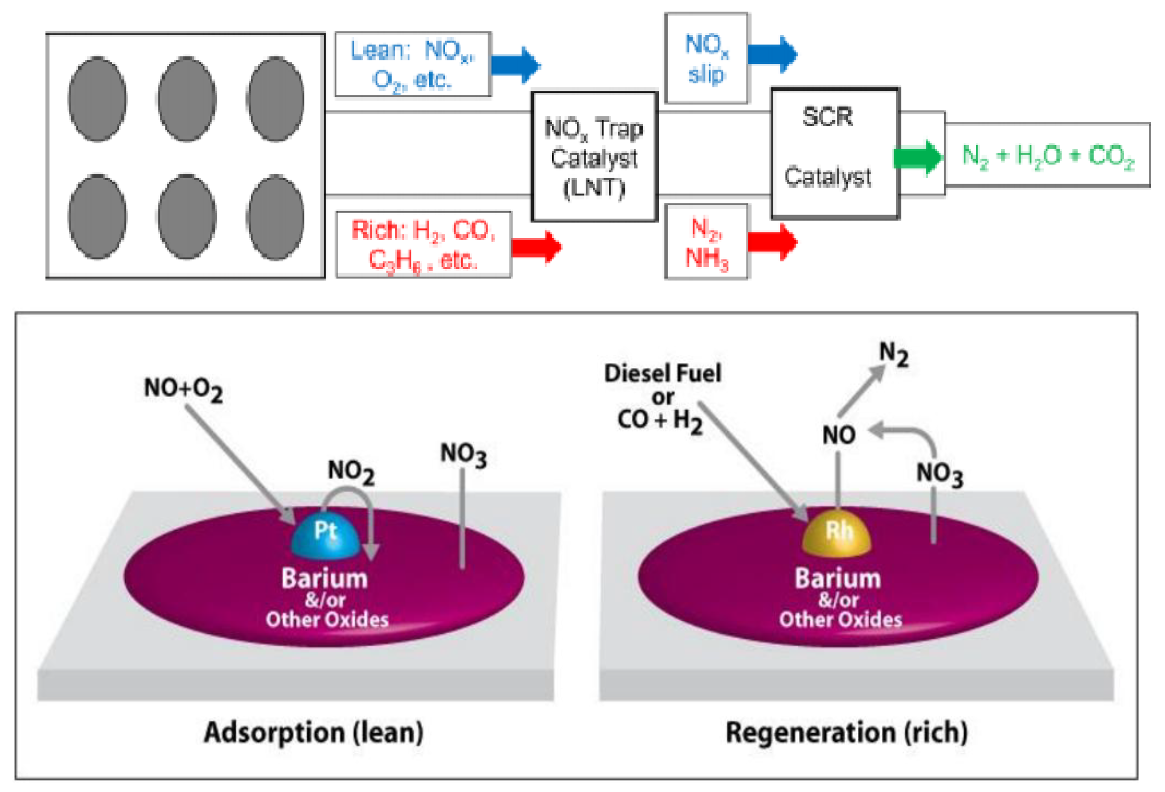
Figure 35.
DeNOx Removal Techniques for Automotive Applications – A[96].
Figure 35.
DeNOx Removal Techniques for Automotive Applications – A[96].
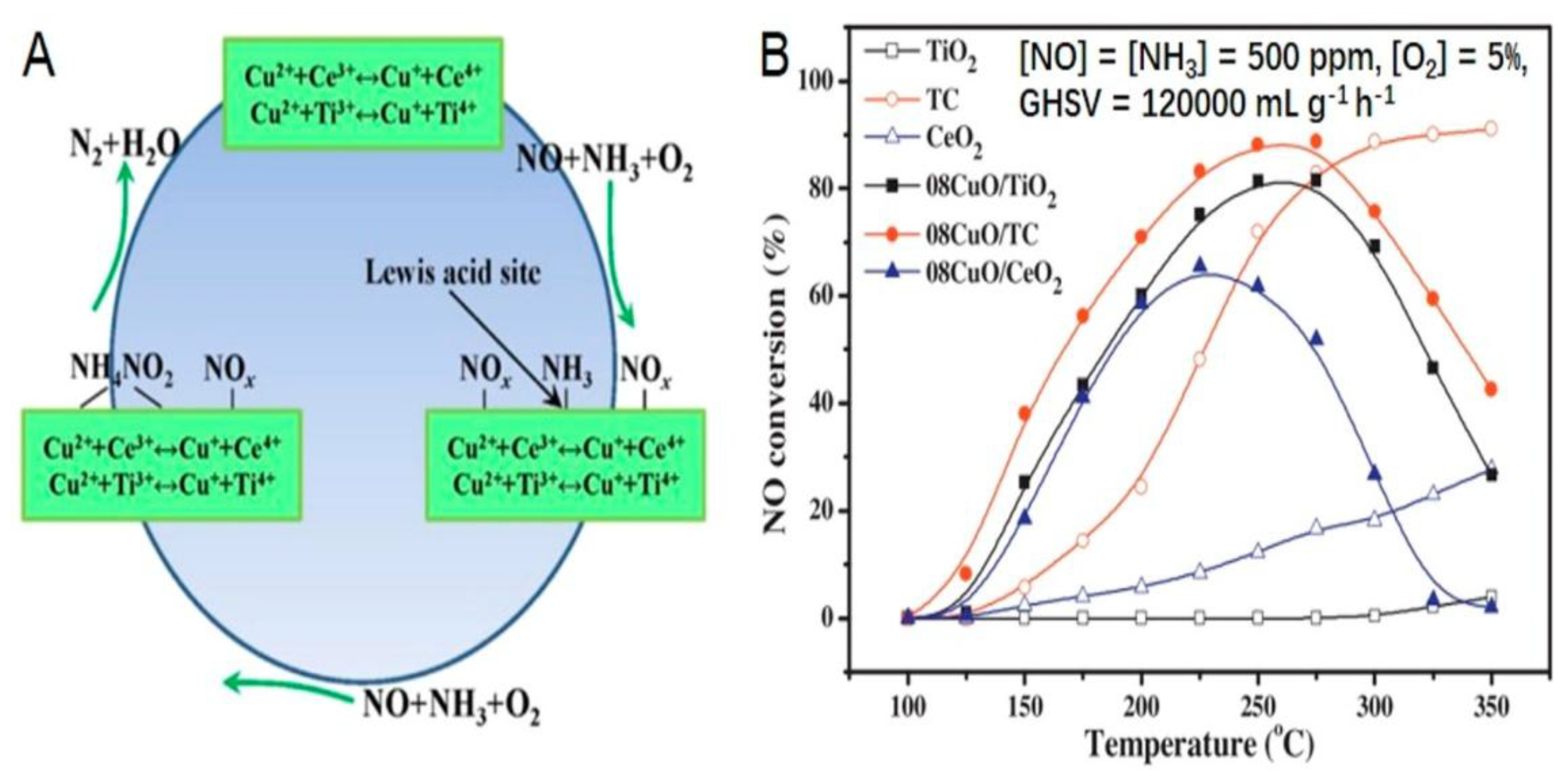
Figure 36.
De-NOX for standard SCR at different catalyst content (a,b)[86,95,97]as a function of temperature, (c) at 10 ppm NH3 slip. Reaction conditions:, NH3 = 300 ppm, O2 = 5%, balance N2, total flow 500 sccm and NOx = 300 ppm [97,98].
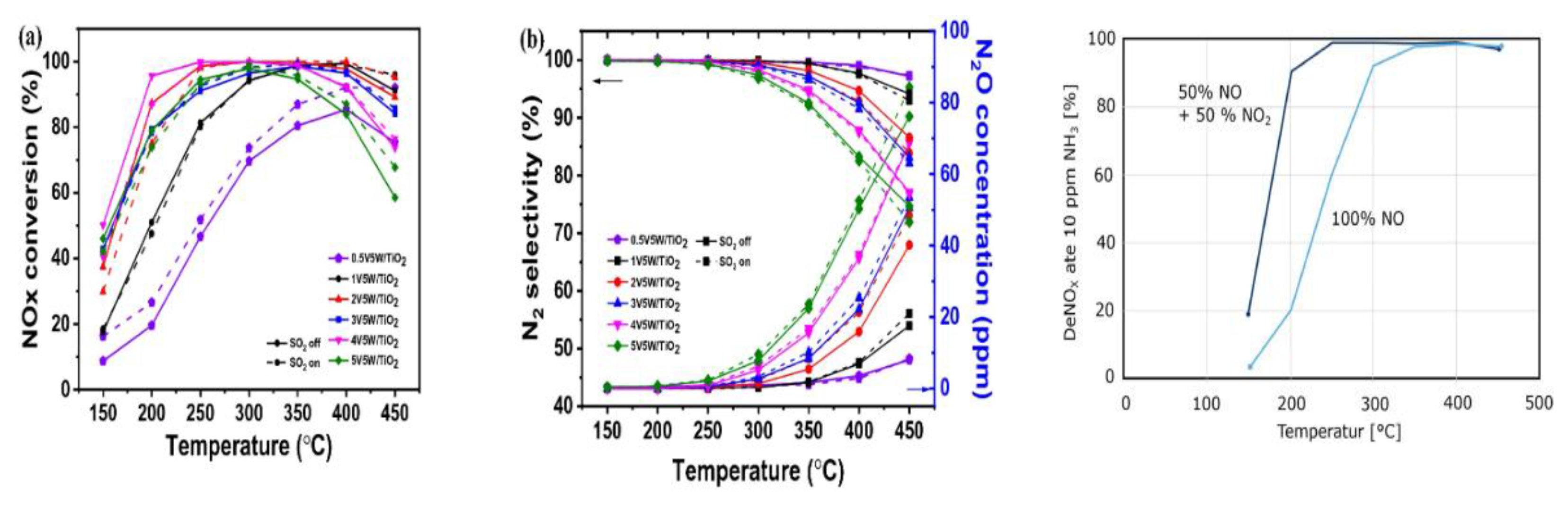

Table 1.
The key factors governing flame stability and NOₓ emissions.
| Factor | Effect on Flame Stability | Effect on NOx Emissions |
|---|---|---|
| Hydrogen addition (10–40%) | Widens stability, increases flame speed | Moderate NO increase at lean; reduction at rich |
| Pressure (5–15 atm) | Improves stability and completeness | Reduces NOx by up to 40% |
| Rich operation (ϕ > 1.1) | Reduces stability slightly | Decreases fuel-NO via NHx radicals |
| Swirl/tangential staging | Enhances stability | Reduces NOx to ~50% with proper flow staging |
| Plasma-assisted combustion | Significantly extends lean limit | 20–40% NOx reduction |
| Heat-recirculating (Swiss-roll) | Broadens stable regime of pure NH₃ | Non-monotonic NO vs ϕ, lower at lean/rich |
| Flameless combustion | Broadens stable regime of pure NH₃, in high temperature | More than 40% NOx reduction |
| Design Criteria | SNCR | SCR |
|---|---|---|
| NOx reduction efficiency | 40-75% | 60-90% |
| Temperature window | 870°-1200°C | 165°-600°C |
| Reactant | Ammonia or Urea | Ammonia or Urea |
| Reactor | None | Catalytic |
| Waste disposal | None | Spent catalyst |
| Thermal efficiency debit | 0 – 0.3% | 0% |
| Energy consumption | Low | *High I.D. fan |
| Capital investment costs | Low | High |
| Plot requirements | Minor | Major |
| Maintenance | Low | 3 – 5 years (typical catalyst life) |
| Ammonia/NOx (molar ratio) | 1.0 – 1.5 | 0.8 – 1.2 |
| Urea/NOx (molar ratio) | 0.5 – 0.75 | Not Applicable |
| Ammonia slip | 5 – 20 **ppmvd | 5 -10 ppmvd |
| Retrofit | Easy | Difficult |
| Mechanical draft | Not Required | Required |
*Induced draft fans (ID fans) often handle air under challenging conditions, such as high temperatures, acidic airstreams, and other extreme exhaust gases. ** ppmvd means parts per million by volume, dry basis.
Disclaimer/Publisher’s Note: The statements, opinions and data contained in all publications are solely those of the individual author(s) and contributor(s) and not of MDPI and/or the editor(s). MDPI and/or the editor(s) disclaim responsibility for any injury to people or property resulting from any ideas, methods, instructions or products referred to in the content. |
© 2025 by the authors. Licensee MDPI, Basel, Switzerland. This article is an open access article distributed under the terms and conditions of the Creative Commons Attribution (CC BY) license (http://creativecommons.org/licenses/by/4.0/).
Copyright: This open access article is published under a Creative Commons CC BY 4.0 license, which permit the free download, distribution, and reuse, provided that the author and preprint are cited in any reuse.


