
Submitted:
25 November 2025
Posted:
27 November 2025
You are already at the latest version
Abstract
This study develops a closed-form solution to predict pressure-driven stress and displacement fields in a thick-walled, functionally graded (FG), incompressible, multi-layer hyperelastic cylinder made from Polyvinyl Chloride (PVC), subjected to internal pressure. The exact solution ensures incompressibility, which finite element methods (FEM) may not guarantee. Properties vary smoothly through the thickness using a Mooney–Rivlin model. Two cases are examined: bi-layer and tri-layer cylinders, where the properties in the second layer of the bi-layer case are 50% lower than the first, and in the tri-layer case, the second- and third-layers’ properties are 30% and 60% lower, respectively. Two material grading conditions are considered: in the first, properties at the largest radius are 1.2 times those at the smallest radius, and in the second, they are 0.8 times. Gradation is modeled using an exponential-logarithmic function. The field equations reduce to a nonlinear scalar condition for the integration constant governing radius mapping, leading to explicit solutions for radial displacement and radial, tangential, and axial stresses under internal pressure. Both analytical and FEM solutions yield identical results, with errors under 1% in all cases. The analysis recovers homogeneous limits and provides conditions where continuous gradation reduces stress concentrations compared to discretely layered baselines.
Keywords:
hyperelastic
; functionally graded materials
; polyvinyl chloride
; large deformation
; Mooney–Rivlin model
; thick-walled cylinder
; closed-form solution
; stress concentrations
; internal pressure
1. Introduction
Exact, large-deformation predictions of pressure-driven stresses in incompressible cylindrical vessels are essential for safe and efficient design under service loads. Finite-strain, calibration-based formulations outperform linearized surrogates, and analytic benchmarks remain vital because volumetric locking and stabilization methods can bias high-pressure stress predictions [1,2,3]. Recent exact and semi-analytical vessel studies show peak stresses are highly sensitive to constitutive model and boundary conditions, driving the need for parameter-transparent predictions [4,5]. Biomedical applications heighten these requirements, while studies of graded elastomers demonstrate that smooth through-thickness property variation reshapes pressure-driven stress profiles, motivating exact treatments of gradation effects [6,7].
Despite established large-deformation vessel studies, a clear gap remains: an exact hyperelastic formulation that predicts pressure–stress fields in continuously graded, multi-layer hyperelastic cylinders subjected to internal pressure. Analytical (ANL) and semi-analytical multilayer treatments provide closed-form relations for layered vessels, but their piecewise-constant property descriptions can obscure how truly continuous gradation redistributes pressure-driven stresses and masks gradation-specific effects [8]. Semi-analytical finite-length and three-dimensional treatments demonstrate the importance of strictly enforcing boundary conditions and incompressibility to control peak stresses, yet most do not couple those enforcement details to a continuous through-thickness gradation [9,10,11]. Independent analyses of FG hyperelastic cylinders show that smooth radial variation in constitutive parameters reshapes radial and hoop stress profiles, motivating continuous gradation laws rather than stepwise layering when accurate, parameter-transparent predictions are required [12]. Benchmark ring and tube studies further show that abrupt stiffness jumps introduce artificial stress discontinuities that complicate comparisons with graded limits, underscoring the need for an exact formulation that preserves incompressibility while eliminating interface artifacts when passing to FG descriptions [13]. Together, these works set a clear target: an exact, closed-form FG finite-strain theory for internally pressurized cylinders that yields parameter-transparent pressure–stress predictions and recovers multilayer and homogeneous results as piecewise-constant and zero-gradient limits, respectively [8,14].
Assuming axisymmetry with plane strain fixes the kinematics and allows exact enforcement of incompressibility. Recent mixed and stabilized formulations demonstrate that substituting an artificially large bulk modulus remains prone to volumetric locking and pressure bias, whereas mixed displacement–pressure schemes preserve reliable stress predictions at finite strain [15,16]. Benchmarks for large-strain hyperelastic elements further show that predicted stress peaks and through-thickness gradients depend critically on how incompressibility and boundary conditions are enforced as well as on the chosen strain-energy form (e.g., Neo-Hookean versus Mooney–Rivlin), reinforcing the need to specify the constitutive class explicitly and to audit enforcement details [17]. In numerical practice, contact algorithms or artificial prescriptions (for example, virtual thermal strains used to mimic assembly loads) can conflate loading kinematics with solution procedures and thereby obscure parameter transparency at interfaces [18,19]. In this study we instead prescribe boundary tractions and geometric constraints directly, enforce exact incompressibility, and require continuity of displacement and stress across layers. Functional gradation is introduced as a smooth radial variation of the stored-energy parameters; recent analyses of graded tubes under coupled inflation–torsion illustrate how continuous laws reshape hoop and axial responses but do not address the combined effect of continuous gradation and explicit boundary-traction prescriptions [20,21,22,23]. These considerations define our modeling choices: axisymmetric, plane-strain, incompressible hyperelasticity with direct enforcement of incompressibility and a smooth FG law tied to the stored-energy parameters [15,16,17,18,20].
Radial equilibrium together with exact incompressibility reduces the boundary-value problem to a single scalar condition for an integration constant that is fixed by the prescribed radial tractions. Once that constant is found, the radial mapping and closed-form expressions for radial displacement and for all stress components follow algebraically. Multilayer analytical treatments make this scalar structure explicit for piecewise-constant parameter distributions [24]. Analytical solutions for FG cylinders (including studies of inflation and coupled loading) preserve the same scalar organization after replacing piecewise constants with smooth radial functions, although many such works treat different loading modes or simplifying assumptions and do not emphasize a traction-based scalar closure for graded materials [25] Other graded-cylinder analyses likewise exploit the scalar reduction but focus on alternate loadings or numerical strategies rather than on an explicit, closed-form traction closure [26,27]. By contrast, finite-element approximations generally require mixed or stabilized formulations to control volumetric locking and spurious pressure oscillations; their accuracy depends sensitively on how near-incompressibility and boundary data are enforced, and an explicit scalar closure typically emerges only through post-processing rather than directly from the discrete formulation [28,29]. This scalar framework yields an analytically tractable basis for quantifying how continuous gradation modifies stress distributions and for producing design-relevant, parameter-transparent maps [24,25,26,28,29].
We present an exact, closed-form solution for the large-deformation radial mapping, displacements, and full stress field of a thick-walled, incompressible, FG multi-layer hyperelastic cylinder under internal pressure. The formulation enforces incompressibility exactly, admits general smooth through-thickness gradation laws (here illustrated with a Mooney–Rivlin model and an exponential–logarithmic gradation), and reduces the boundary-value problem to a single scalar closure whose solution yields algebraic expressions for radial, hoop and axial stresses. The theory recovers piecewise-constant multilayer and homogeneous limits and is applied to representative bi-layer and tri-layer PVC [30] cases with two gradation variants. Analytical predictions are benchmarked against mixed/hybrid finite-element solutions. Parametric studies quantify how grading strength and layer contrasts govern stress smoothing and peak magnitudes, producing directly usable maps for design of graded elastomer pressure vessels. The closed-form base state also enables straightforward extensions (incremental stability, non-axisymmetric or finite-length numerical studies, and thermo-mechanical coupling).
2. Materials and Methods
2.1. Materials
2.1.1. Material Model and Properties
In continuum mechanics, hyperelastic materials are characterized by an energy density function. In this study, the Mooney-Rivlin model was employed, which consists of two material parameters, denoted as C10 and C01.
To incorporate FG distribution of these material constants, two cases were studied: one with increasing and the other with decreasing material properties as the radius increases. Multiplication factors (MFs) of 1.2 and 0.8 were used to scale the properties to their maximum and minimum values from the base values. The main values, which maximization and minimization were performed on, were chosen by the properties belong to PVC, which are reported in Table 1.
In each case study, regardless of the number of layers and whether the material properties increase or decrease with the radius, two values were defined for each parameter within a layer. For instance, C10, max and C10, min refer to the maximum and minimum values of C10 within the layer. Similarly, C01, max and C01, min refer to the maximum and minimum values of C01 within the same layer. The C10 and C01 properties of PVC were utilized for the first layer.
Additionally, in this study, two cases of bi-layer and multi-layer cylinders were analyzed. In both cases, the material properties of the inner layer were higher than those of the outer layers. This is because the inner layer is in direct contact with the location where the pressure is applied, requiring to be stronger. In the bi-layer cylinder, the properties of the second layer were 50% lower than those of the first layer. The material properties of the bi-layer cylinder with two MFs of 0.8 and 1.2 are provided in Table 2 and Table 3, respectively.
2.2. Methods
2.2.1. Analytical Solution
Figure 1 illustrates the schematic of a thick, long, multi-layer cylinder under radial pressure. Due to the infinite length of the cylinder, plain strain assumption is made to simplify the analytical approach, as the longitudinal variation of stress and displacement fields can be neglected. A distinct material is assigned to each layer of the cylinder, and the thickness can vary from one layer to another. However, in this study, equal thickness is assumed to all layers. Given the theory of hyperelasticity, which is a branch of nonlinear mechanics, the proposed analytical solution must be capable of capturing large deformation and inflation caused by the applied radial pressure.
The inner and outer radial pressures are denoted as and , respectively. Each layer consists of two radii: the inner and outer radii, denoted as , respectively. The radii correspond to the inner radius of the first, second, third, and the last layer, respectively.
The general form of the deformation gradient in the cylindrical coordinate system [33] is as follows:
In this problem, all fields depend only on the reference radial coordinate, so the deformation is represented by the monotone radial mapping,
where and are the current and reference radii. Using this assumption, the deformation gradient tensor is defined as:
The left Cauchy-Green deformation tensor is given as follows:
The first three principal invariants of the left Cauchy-Green deformation tensors are defined as as follows:
Exact incompressibility closes the kinematics through the radial identity as follows:
The displacement field is defined as:
Integration of the incompressibility relation yields an explicit primitive for mapping,
where is the integration constant.
To impose the continuity condition on the radial deformation of the successive layers, the following steps were taken:
was substituted from Eq. (9) into Eq. (11):
which concludes:
This implies that does not change from one layer to another.
For an incompressible hyperelastic cylinder, the Mooney-Rivlin model [34] is defined as:
where are the material constants.
To obtain an expression for the different components of Cauchy stress, the second Piola stress was first defined as:
The derivatives of the principal invariants with respect to the right Cauchy-Green deformation tensor can be calculated as:
By substituting Eq. (16) into Eq. (15), the expression for the second Piola stress tensor [35] is as follows:
The Cauchy stress formula can be written using its relation with the second Piola stress as follows:
The index notation for Eq. (18) is:
An incompressible material is only deformed when subjected to isochoric stress, which is denoted as Incompressibility constraint does not allow the material to change its volume, so volumetric stress, which is denoted as plays no role in material deformation.
The total stress, which is the summation of isochoric and volumetric stress, is defined as follows:
where is the kronecker delta, defined as:
The principal stress is defined as:
Eq. (18) is simplified by using the Eq. (22), as:
The radial, tangential, and axial stress components, denoted as , respectively, are defined using Eq. (23):
In polar coordinates, in the absence of body forces, the radial stress equilibrium is defined as follows:
Now, the expression related to and can be substituted from Eq. (24) and Eq. (25), respectively into Eq. (27):
Using Eq. (8), Eq. (28) becomes:
Then, integration is applied to both sides of Eq. (29):
By using Eq. (10), Eq. (30) is rewritten as follows:
Eq. (31) is suitable for problems where material properties are assumed to be homogenous. To generalize the solution for heterogeneous material distributions, a FG approach is employed for the Mooney-Rivlin material parameters, C10 and C01.
To account for the FG distribution, an exponential-logarithmic distribution form of C10 and C01 is defined in Eq. (32) and Eq. (33), respectively:
The homogeneous limit is recovered when The expressions for are required to be substituted into Eq. (31) to employ the integration process. To facilitate integration, the Taylor expansion is used for the exponential part of Eq. (32) and Eq. (33), expanded up to four sentences. The expansion is used as follows:
Now, are substituted into Eq. (31):
where denotes the pressure applied on the radius of . The above integral requires a long-hand solution. The final closed-form solution is reported in Appendix A.1.
By considering , Eq. (36) becomes as follows:
where denotes the pressure applied on the radius of , which is equal to .
To obtain , which is the same for all layers within the cylinder, Eq. (37) must be solved successively, as shown in Eq. (38):
where are the minimum and maximum values of and in the m-th layer, respectively. , denote the inner and outer radii of the m-th layer. Also, to implement the traction free of outermost surface, is considered zero.
By starting from the outer radius and solving Eq. (37) successively, the pressure applied on each boundary radius is obtained.
After solving Eq. (36), the tangential and axial stresses are calculated in Eq. (39) and Eq. (40), respectively:
2.2.2. Finite Element Solution
To verify the analytical solution, finite element analysis of bi-layer and multi-layer cylinders subjected to internal pressure was carried out using COMSOL Multiphysics software. To capture hyperelasticity and large deformation, a Mooney-Rivlin material model was used. This model includes two material parameters, denoted as C10 and C01.
2.2.2.1. Geometry
One quarter of each cylinder was modeled to reduce the simulation runtime. The geometries of the bi-layer and multi-layer cylinders are illustrated in Figure 2.a and Figure 2.b, respectively. No gap or interference was assumed between the layers. The outer layer is highlighted in blue in each case.
The inner and outer radii of each layer for the bi-layer and multi-layer cases are presented in Table 6 and Table 7, respectively.
2.2.2.2. Boundary Conditions
To prevent any undesirable movement of the cylinders, two displacement-type boundary conditions were imposed. The vertical displacements of radii that lie horizontally in parallel to the x-axis were prescribed as zero, and the horizontal displacements of radii that lie vertically in parallel to the y-axis were prescribed as zero. Radial pressure is directly applied to the inner radius of the cylinder. To ensure symmetric results, a symmetry boundary condition was defined for the radii that are parallel to the x-axis and y-axis
3. Results
3.1. The Bi-Layer Cylinder
3.1.1. Increasing Material Properties with Increasing Radius
The radial displacement and stress distributions of the bi-layer cylinder in the case of increasing material properties with increasing radius are shown in Figure 3a, 3.b, 3.c, and 3.d, respectively.
The error between the analytical and finite element solutions in the bi-layer cylinder, in the case of increasing material properties with increasing radius, is reported in Table 8.
3.1.2. Decreasing Material Properties with Increasing Radius
The radial displacement and stress distributions of the bi-layer cylinder in the case of decreasing material properties with increasing radius are shown in Figure 4a, 4b, 4c, and 4d, respectively.
The error between the analytical and finite element solutions in the bi-layer cylinder, in the case of decreasing material properties with increasing radius, is reported in Table 9.
3.2. The Multi-Layer Cylinder
3.2.1. Increasing Material Properties with Increasing Radius
The radial displacement and stress distributions of the multi-layer cylinder in the case of increasing material properties with increasing radius are shown in Figure 5a, 5b, 5c, and 5d, respectively.
The error between the analytical and finite element solutions in the multi-layer cylinder, in the case of increasing material properties with increasing radius, is reported in Table 10.
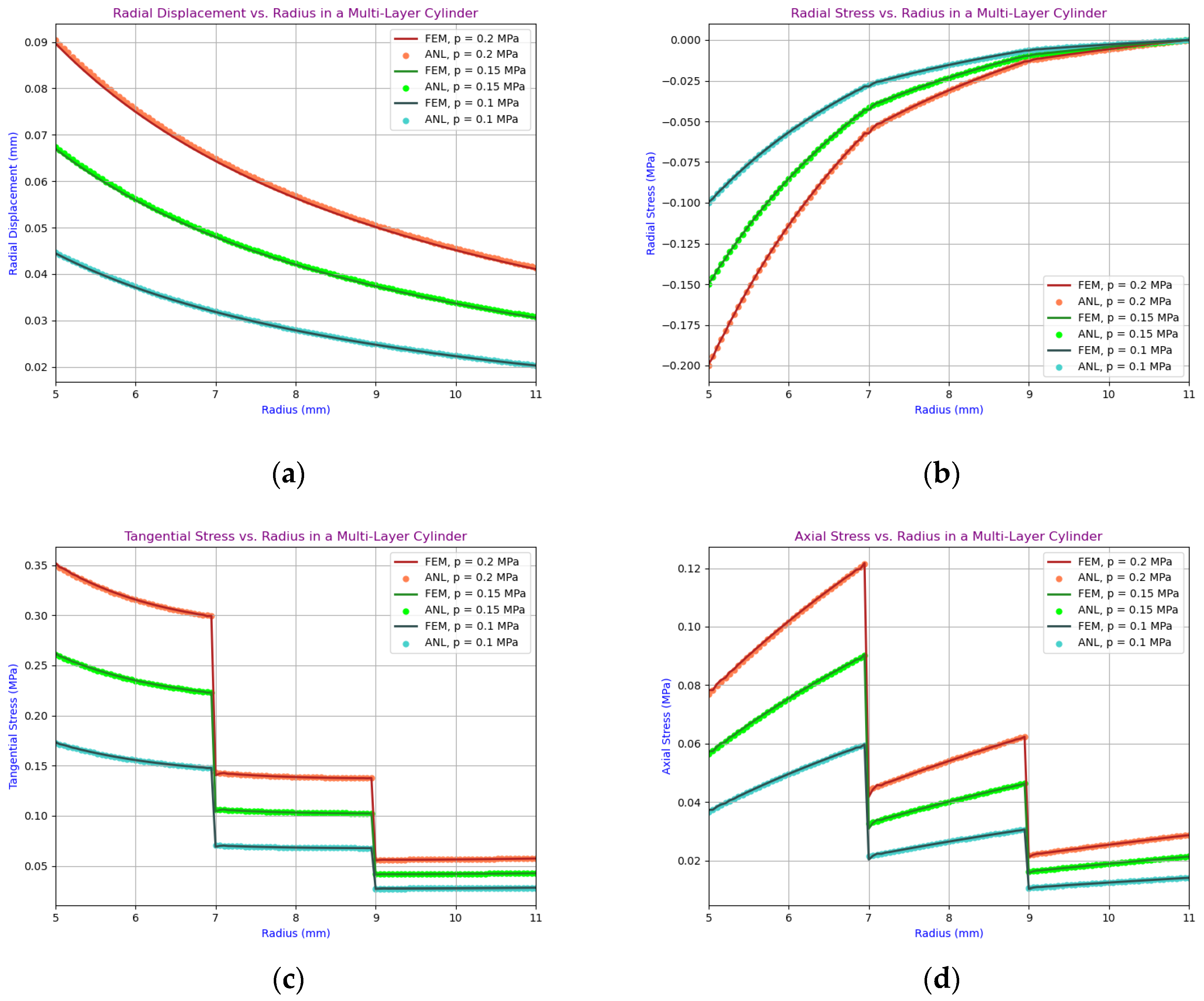
3.1.2. Decreasing Material Properties with Increasing Radius
The radial displacement and stress distributions of the multi-layer cylinder in the case of decreasing material properties with increasing radius are shown in Figure 6.a, 6.b, 6.c, and 6.d, respectively.
The error between the analytical and finite element solutions in the multi-layer cylinder, in the case of decreasing material properties with increasing radius, is reported in Table 11.
4. Discussion
In this study, two cases of bi-layered and multi-layered thick-walled, functionally graded, hyperelastic cylinders subjected to internal pressure are investigated. The Mooney-Rivlin material model is used to account for the hyperelasticity and large deformation. Distinct material properties are assigned to each layer of the cylinder. The analytical formulation ensures the incorporation of incompressibility conditions, which is not guaranteed when using numerical software such as COMSOL. The continuity condition of the radial displacement is also defined as a constraint to ensure that its values at the shared edges are compatible with each other.
According to Figure 3Figures toFigure 6, the comparison between the distributions of radial displacement and stress components, including radial, tangential, and axial, derived from both the numerical and analytical solutions, shows excellent agreement, which indicates that the proposed analytical solution can properly predict the fields across the layers of the cylinder.
According to the second subfigures of Figure 3Figures toFigure 6, the inner layer, which is in direct contact with the applied pressure, demonstrates the highest amount of stress compared to the outer layers, which are significantly smaller due to their lower material properties. This behavior is observed in both the bi-layer and multi-layer cylinders, indicating that, regardless of the number of layers, more compliant materials lead to lower stress concentration. Both the tangential and axial stresses are tensile, which is typical for pressurized cylinders. Both stress components show discontinuities at the interfaces between layers due to the differences in material properties.
In this work, three values of 0.2, 0.15, and 0.1 MPa for internal pressure are investigated for each material gradation case. Regardless of the number of layers, excellent agreement between the analytical and FEM solutions, with errors below 1% is recorded. As the internal pressure increases, the magnitude of the stress components follow the same trend and increase, and the errors increase slightly. This observation highlights the sensitivity of the error margin to higher internal pressures, but the discrepancies remain small and within an acceptable range.
The findings can provide valuable insights for designing FG pressurized cylinders, as the stress and displacement distributions can be optimized by selecting appropriate material properties across the thickness of the cylinder, which leads to more efficient and durable designs. The proposed closed-form solution can be used by engineers and designers to predict the behavior of multi-layer, functionally graded, hyperelastic cylinders under pressure, without the need for complex and time-consuming numerical simulations.
Engineers should also consider the material gradation to achieve a more uniform stress distribution, which is essential for the structural integrity of the vessels. Multi-layer cylinders with smoothly varying properties across the radius demonstrate reduced stress concentrations and improved overall performance when subjected to internal pressure.
Future research could explore the addition of viscoelastic behavior, where time-dependent deformations and energy dissipation play an important role under cyclic loading conditions. In order to further provide insight into this prediction, incorporation of damage mechanics into the model could be a promising approach for failure prediction. particularly when fatigue or localized material degradation are concerns for designers. Additionally, the use of shape memory behavior could be an interesting avenue for future work, particularly in systems where self-healing or adaptive responses to external loads are desired.
Author Contributions
E. S.: conceptualization, methodology, software, formal analysis, visualization, writing—original draft. M.A.-S.: conceptualization, methodology, validation, writing—review and editing. A.O.: supervision, project administration, writing—review and editing. E.C.: supervision, project administration, writing—review and editing. M.B. (Majid Baniassadi): supervision, writing—review and editing, M.B. (Mostafa Baghani): supervision, methodology, writing—review and editing. All authors have read and agreed to the published version of the manuscript.
Funding
E.C. acknowledges funding from the National Research Foundation of Korea (NRF), which is funded by the Korean government (MEST) (Project No. RS-2024-00341914).
Data Availability Statement
The data presented in this study are available on request from the corresponding author. The data are not publicly available due to privacy concerns.
Acknowledgments
The authors have reviewed and edited the output and take full responsibility for the content of this publication.
Conflicts of Interest
The authors declare no conflicts of interest.
Abbreviations
The following abbreviations are used in this manuscript:
| FG | Functionally Graded |
| PVC | Polyvinyl Chloride |
| FEM | Finite Element Method |
| ANL | Analytical |
| MF | Multiplication Factor |
Appendix A
Appendix A.1
The closed-form analytical solution obtained after integrating Eq. (36), as expressed in Eq. (A1), involves the parameters , , , , , , with , , and representing the integration constant.
References
- Karabelas, E. , et al., An accurate, robust, and efficient finite element framework with applications to anisotropic, nearly and fully incompressible elasticity. Computer Methods in Applied Mechanics and Engineering 2022, 394, 114887. [Google Scholar] [CrossRef] [PubMed]
- Gao, J. , et al., Energy-based multi-axial fatigue prediction for tubular structures under non-proportional loading. International Journal of Fatigue 2025, 197, 108897. [Google Scholar] [CrossRef]
- Yu, X., Y. Fu, and H. -H. Dai, A refined dynamic finite-strain shell theory for incompressible hyperelastic materials: equations and two-dimensional shell virtual work principle. Proceedings of the Royal Society A: Mathematical, Physical and Engineering Sciences 2020, 476, 20200031. [Google Scholar]
- Shojaeifard, M., K. Wang, and M. Baghani, Large deformation of hyperelastic thick-walled vessels under combined extension-torsion-pressure: analytical solution and FEM. Mechanics Based Design of Structures and Machines 2022, 50, 4139–4156. [Google Scholar] [CrossRef]
- Xie, W.-T. , et al., Auxiliary support path planning for robot-assisted machining of thin-walled parts with non-uniform thickness and closed cross-section based on a neutral surface. Journal of Manufacturing Processes 2025, 147, 16–28. [Google Scholar] [CrossRef]
- Shojaeifard, M. , et al. Analytical and Finite Element Solution for Functionally Graded Pressure Vessels Subjected to Finite Strain Coupled Axial and Torsional Deformations. Materials 2025, 18. [Google Scholar] [CrossRef]
- Takada, J. , et al., Biaxial tensile testing system for measuring mechanical properties of both sides of biological tissues. Journal of the Mechanical Behavior of Biomedical Materials 2023, 146, 106028. [Google Scholar] [CrossRef]
- Shariyat, M. and M. Momeni, Exact large deformation and stress analysis of shrink-fit multi-layer thick-walled/sandwich pressurized hyperelastic cylinders. International Journal of Non-Linear Mechanics 2025, 175, 105112. [Google Scholar] [CrossRef]
- Ariatapeh, M.Y., M. Shariyat, and M. Khosravi, Semi-Analytical Large Deformation and Three-Dimensional Stress Analyses of Pressurized Finite-Length Thick-Walled Incompressible Hyperelastic Cylinders and Pipes. International Journal of Applied Mechanics 2022, 15, 2250100. [Google Scholar] [CrossRef]
- Zou, D. , et al., A device capable of customizing nonlinear forces for vibration energy harvesting, vibration isolation, and nonlinear energy sink. Mechanical Systems and Signal Processing 2021, 147, 107101. [Google Scholar] [CrossRef]
- Shariyat, M. , et al., Nonlinear stress and deformation analysis of pressurized thick-walled hyperelastic cylinders with experimental verifications and material identifications. International Journal of Pressure Vessels and Piping 2020, 188, 104211. [Google Scholar] [CrossRef]
- Ghadiri Rad, M.H., F. Shahabian, and S.M. Hosseini, A meshless local Petrov–Galerkin method for nonlinear dynamic analyses of hyper-elastic FG thick hollow cylinder with Rayleigh damping. Acta Mechanica 2015, 226, 1497–1513. [Google Scholar] [CrossRef]
- Breslavsky, I.D. , et al., Axisymmetric deformations of circular rings made of linear and Neo-Hookean materials under internal and external pressure: A benchmark for finite element codes. International Journal of Non-Linear Mechanics 2016, 84, 39–45. [Google Scholar] [CrossRef]
- Salehi Kolahi, M.R., H. Rahmani, and H. Moeinkhah, Mechanical analysis of shrink-fitted thick FG cylinders based on first order shear deformation theory and FE simulation. Proceedings of the Institution of Mechanical Engineers, Part C: Journal of Mechanical Engineering Science 2021, 235, 6388–6397. [Google Scholar]
- Codina, R., I. Castañar, and J. Baiges, Finite element approximation of stabilized mixed models in finite strain hyperelasticity involving displacements and stresses and/or pressure—An overview of alternatives. International Journal for Numerical Methods in Engineering 2024, 125, e7540. [Google Scholar] [CrossRef]
- Fu, G. , et al. , A four-field mixed formulation for incompressible finite elasticity. Computer Methods in Applied Mechanics and Engineering 2025, 444, 118082. [Google Scholar]
- Pagani, A. , et al., Unified three-dimensional finite elements for large strain analysis of compressible and nearly incompressible solids. Mechanics of Advanced Materials and Structures 2024, 31, 117–137. [Google Scholar] [CrossRef]
- Castagnetti, D. and E. Dragoni, Stress distributions around the interference fit between a round pin and a perforated finite plate. Journal of the Brazilian Society of Mechanical Sciences and Engineering 2024, 46, 219. [Google Scholar]
- Zhu, J., X. Wang, and Y. Mu, Uncertain constitutive model for metals in the presence of inherent defects. Computer Methods in Applied Mechanics and Engineering 2025, 447, 118355. [Google Scholar]
- Batra, R.C. and K.A. Fairclough, Coupled torsion and inflation of functionally graded and residually stressed Mooney–Rivlin hollow cylinders. Mathematics and Mechanics of Solids 2024, 30, 1161–1187. [Google Scholar] [CrossRef]
- Liu, Y. , et al., Analytical model for corrugated rolling of composite plates considering the shear effect. Journal of Manufacturing Processes 2025, 134, 1069–1081. [Google Scholar] [CrossRef]
- Almasi, A., M. Baghani, and A. Moallemi, Thermomechanical analysis of hyperelastic thick-walled cylindrical pressure vessels, analytical solutions and FEM. International Journal of Mechanical Sciences 2017, 130, 426–436. [Google Scholar] [CrossRef]
- Anani, Y. and G.H. Rahimi, Stress analysis of thick pressure vessel composed of functionally graded incompressible hyperelastic materials. International Journal of Mechanical Sciences 2015, 104, 1–7. [Google Scholar] [CrossRef]
- Ghannad, M., M. Jabbari, and M. Zamani Nejad, An elastic analysis for thick cylindrical pressure vessels with variable thickness. Engineering Solid Mechanics 2015, 3, 117–130. [Google Scholar]
- Das, P. , et al., A thermo-mechanically loaded rotating FGM cylindrical pressure vessels under parabolic changing properties: An analytical and numerical analysis. Heliyon 2024, 10, e25969. [Google Scholar] [CrossRef]
- Markides, C., E. Pasiou, and S. Kourkoulis, A multi-layered ring under parabolic pressure. 2016. 64, 433-440.
- Zhang, P. , et al., On the Magnetically Tunable Free Damped-Vibration of L-Shaped Composite Spherical Panels Made of GPL-Reinforced Magnetorheological Elastomers: An Element-Based GDQ Approach. Thin-Walled Structures 2026, 218, 113987. [Google Scholar] [CrossRef]
- Castañar, I., R. Codina, and J. Baiges, A stabilized mixed three-field formulation for stress accurate analysis including the incompressible limit in finite strain solid dynamics. International Journal for Numerical Methods in Engineering 2023, 124, 2341–2366. [Google Scholar] [CrossRef]
- Kadapa, C. , Mixed displacement–pressure formulations and suitable finite elements for multimaterial problems with compressible and incompressible models. Computer Methods in Applied Mechanics and Engineering 2024, 432, 117354. [Google Scholar] [CrossRef]
- Najafipour, M. and M. Shariyat, A refined first-order shear deformation theory for large dynamic and static deflection investigations of abruptly/harmonically pressurized/blasted incompressible circular hyperelastic plates. Ocean Engineering 2023, 289, 116185. [Google Scholar] [CrossRef]
- Schierz, M. and A. Hasse The Influence of Reverse Yielding on the Plastic Conditioning of Interference Fits in Power Transmission Engineering. Applied Mechanics 2024, 5, 73–90. [Google Scholar] [CrossRef]
- Chen, X. , et al., Effect of interference magnitude on fretting wear and fatigue strength of scaled press-fitted railway axles. Wear, 2024. 546-547, 205347. [Google Scholar]
- Askari-sedeh, M. and M. Baghani, On the extension-torsion of short hyperelastic tubes of axially functionally-graded materials. Engineering Structures 2024, 301, 117344. [Google Scholar] [CrossRef]
- Yao, W., H. S. Kim, and C.I. Kim On the Mechanics of a Fiber Network-Reinforced Elastic Sheet Subjected to Uniaxial Extension and Bilateral Flexure. Mathematics 2025. 13. [CrossRef]
- Askari-Sedeh, M. and M. Baghani, Semi-analytical modeling of electro-strictive behavior in dielectric elastomer tube actuators. Physica Scripta 2024, 99, 055503. [Google Scholar] [CrossRef]
Figure 1.
Schematic of a multi-layer cylinder subjected to inner () and outer () radial pressure.
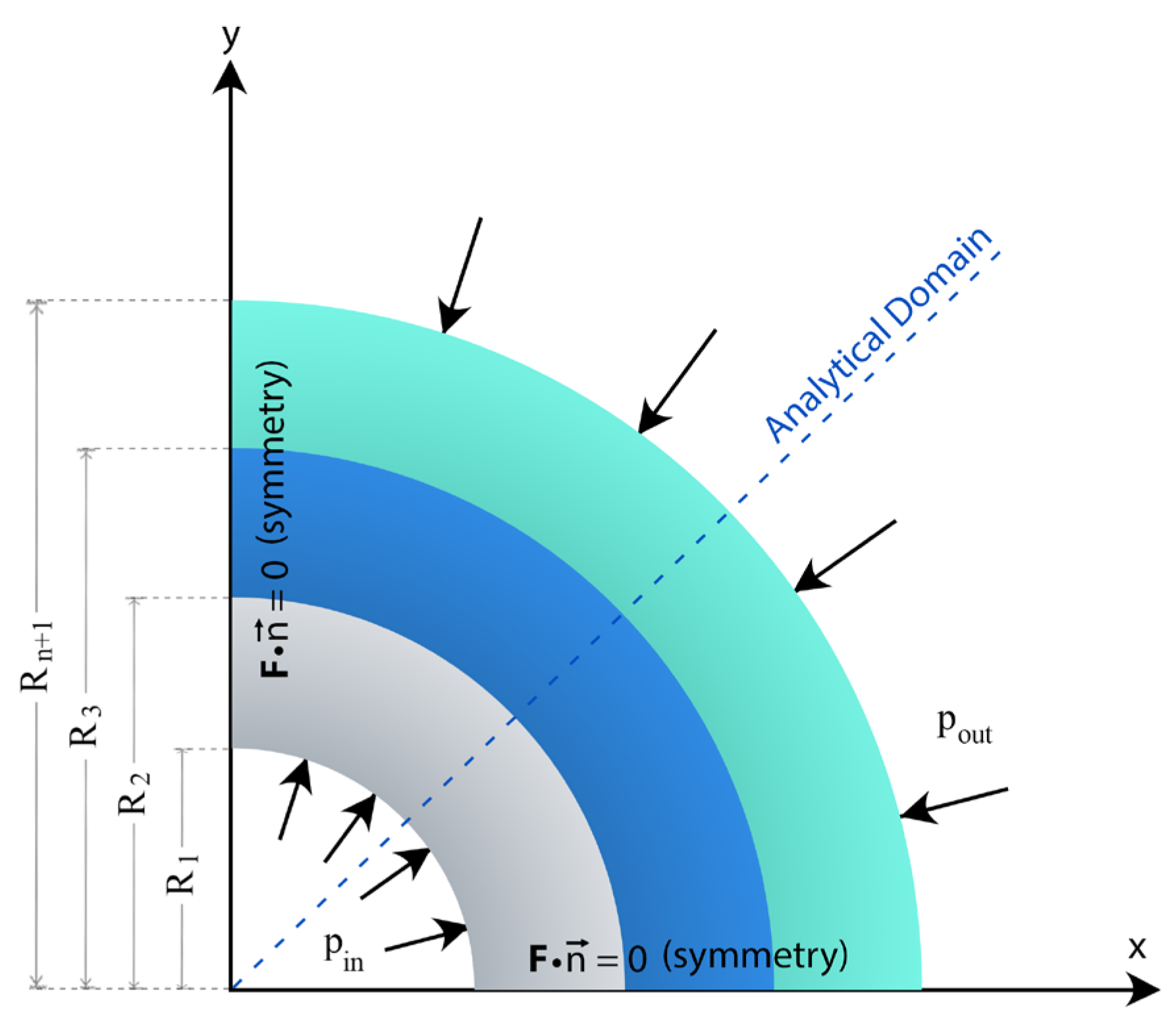
Figure 2.
Geometry: (a) The bi-layer cylinder; (b) The multi-layer cylinder.
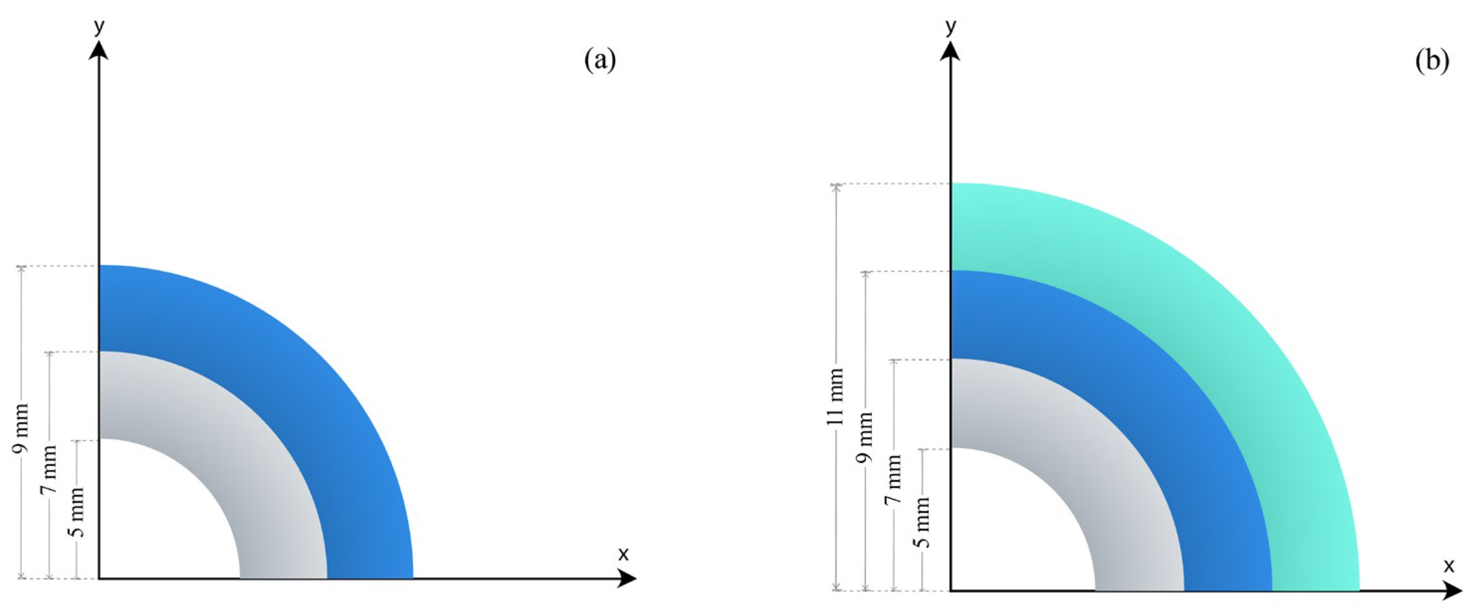
Figure 3.
Radial displacement and stress distributions of the bi-layer cylinder in the case of increasing material properties with increasing radius: (a) Radial displacement; (b) Radial stress; (c) Tangential stress; (d) Axial stress.
Figure 3.
Radial displacement and stress distributions of the bi-layer cylinder in the case of increasing material properties with increasing radius: (a) Radial displacement; (b) Radial stress; (c) Tangential stress; (d) Axial stress.
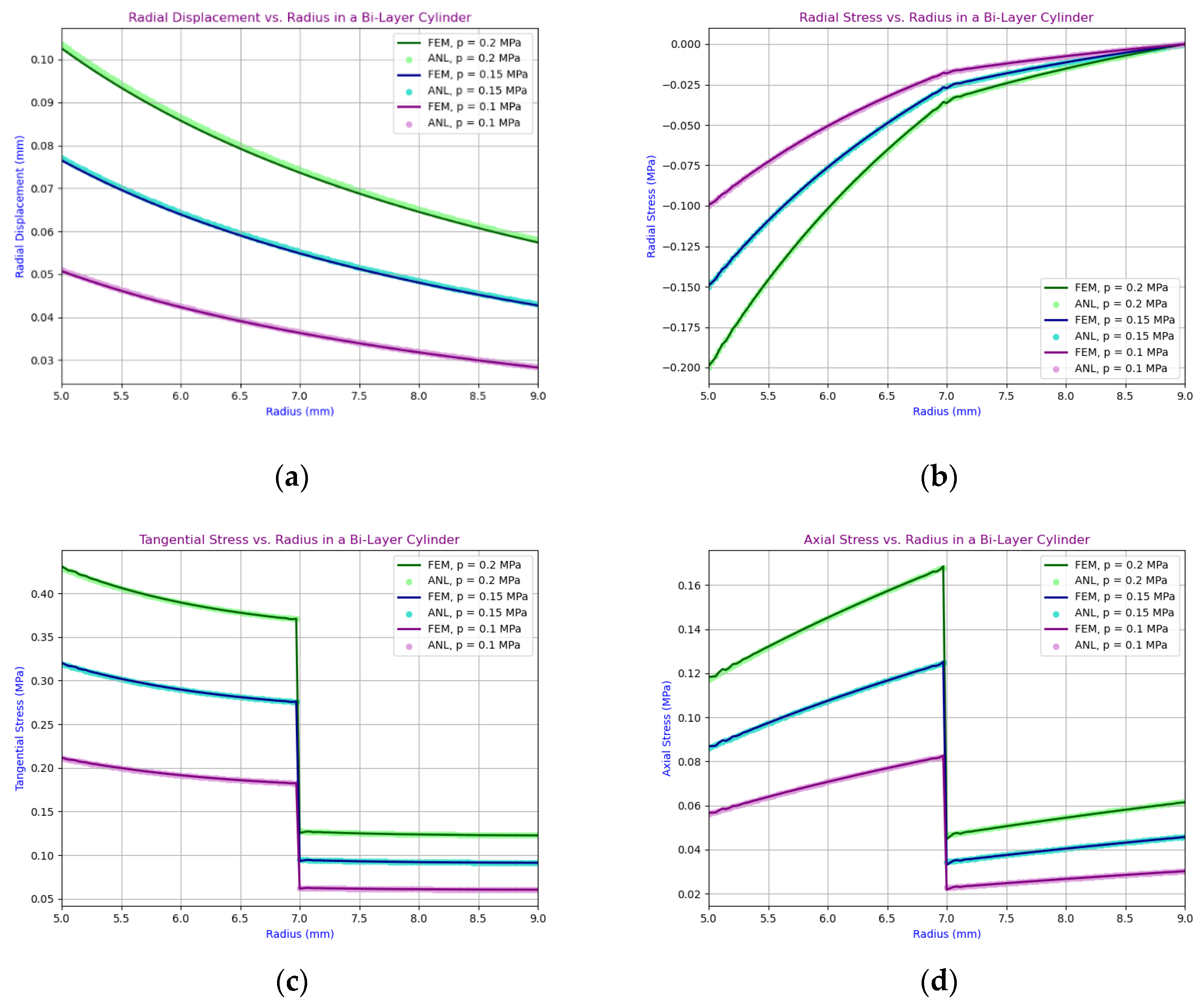
Figure 4.
Radial displacement and stress distributions of the bi-layer cylinder in the case of decreasing material properties with increasing radius: (a) Radial displacement; (b) Radial stress; (c) Tangential stress; (d) Axial stress.
Figure 4.
Radial displacement and stress distributions of the bi-layer cylinder in the case of decreasing material properties with increasing radius: (a) Radial displacement; (b) Radial stress; (c) Tangential stress; (d) Axial stress.
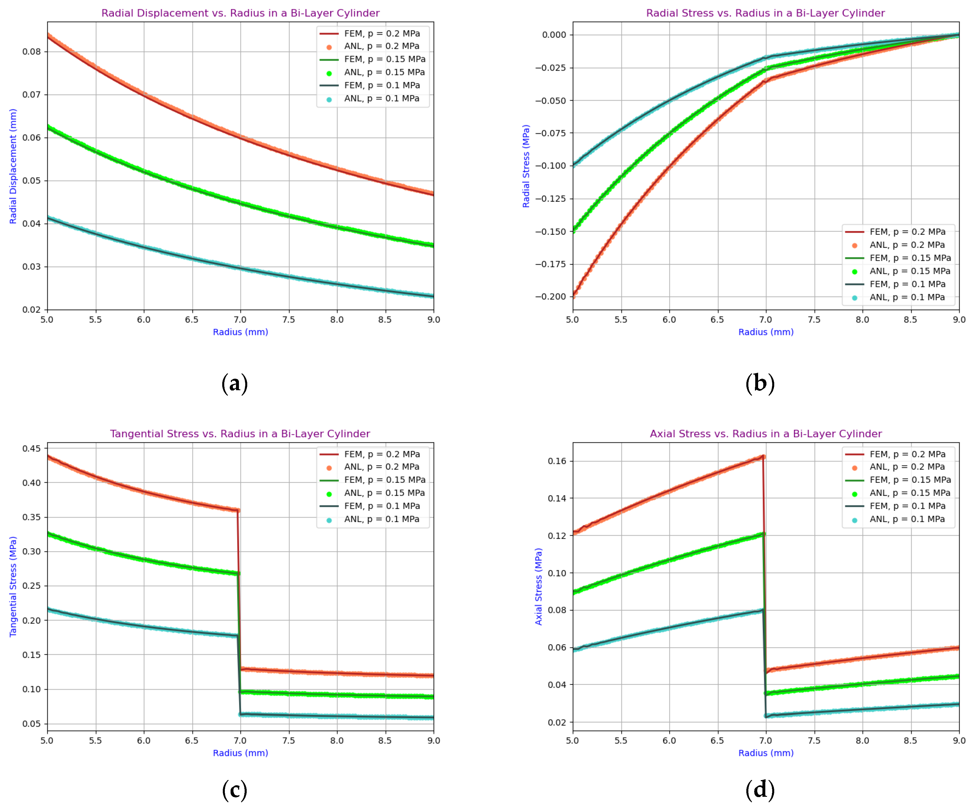
Figure 5.
Radial displacement and stress distributions of the multi-layer cylinder in the case of increasing material properties with increasing radius: (a) Radial displacement; (b) Radial stress; (c) Tangential stress; (d) Axial stress.
Figure 5.
Radial displacement and stress distributions of the multi-layer cylinder in the case of increasing material properties with increasing radius: (a) Radial displacement; (b) Radial stress; (c) Tangential stress; (d) Axial stress.
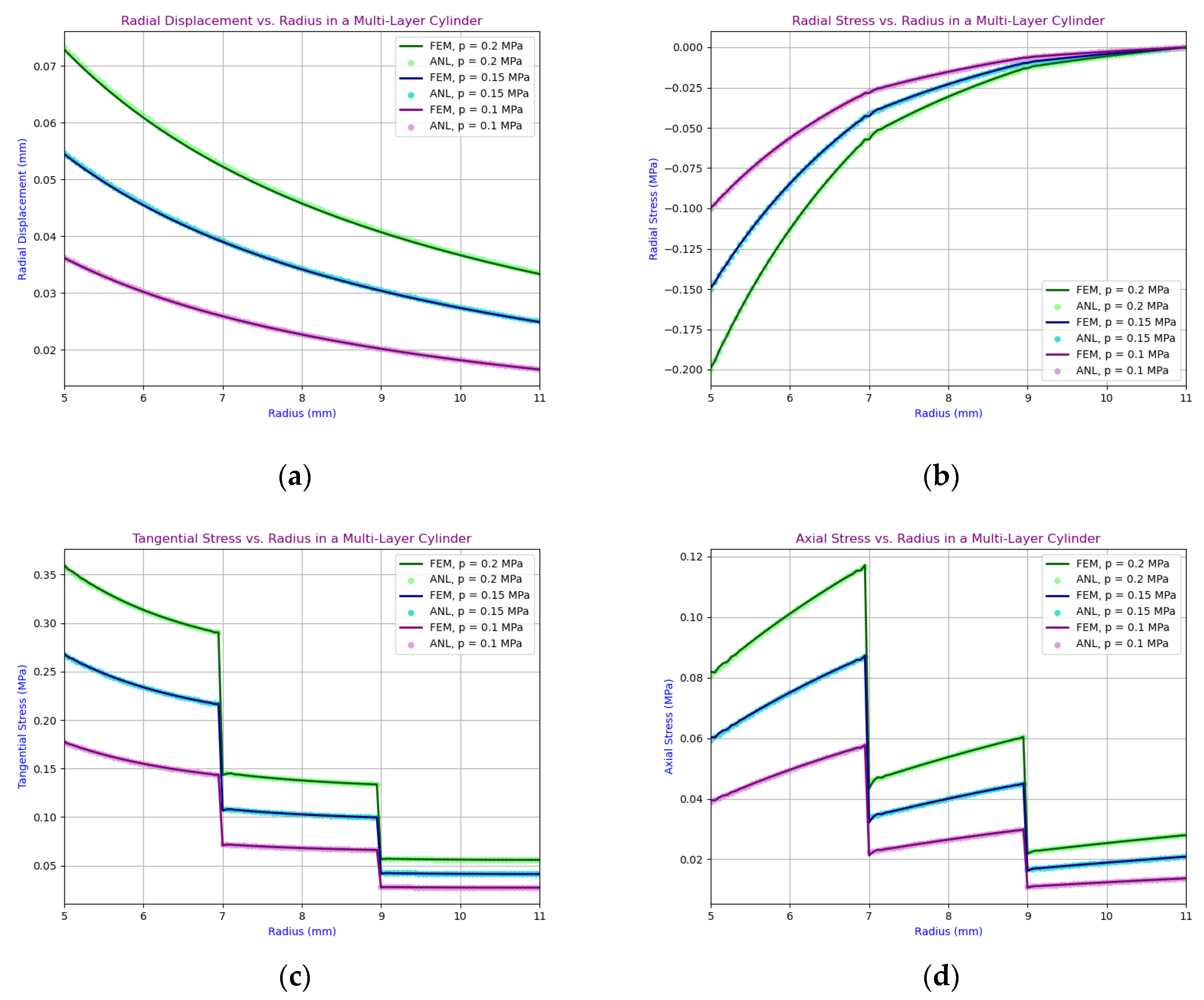
Figure 6.
Radial displacement and stress distributions of the multi-layer cylinder in the case of decreasing material properties with increasing radius: (a) Radial displacement; (b) Radial stress; (c) Tangential stress; (d) Axial stress.
Figure 6.
Radial displacement and stress distributions of the multi-layer cylinder in the case of decreasing material properties with increasing radius: (a) Radial displacement; (b) Radial stress; (c) Tangential stress; (d) Axial stress.

| Material | C10 [MPa] | C01 [MPa] |
|---|---|---|
| PVC | 1.4780 | 3.3150 |
Table 2.
Mooney-Rivlin hyperelastic properties of the bi-layer cylinder (MF: 1.2).
| Layer | C10, min [MPa] (at Rout) |
C10, max [MPa] (at Rin) |
C01, min [MPa] (at Rout) |
C01, max [MPa] (at Rin) |
|---|---|---|---|---|
| Inner | 1.478 | 1.7736 | 3.315 | 3.978 |
| Outer | 0.7390 | 0.8868 | 1.6575 | 1.989 |
Table 3.
Mooney-Rivlin hyperelastic properties of the bi-layer cylinder (MF: 0.8).
| Layer | C10, max [MPa] (at Rout) |
C10, min [MPa] (at Rin) |
C01, max [MPa] (at Rout) |
C01, min [MPa] (at Rin) |
|---|---|---|---|---|
| Inner | 1.478 | 1.1824 | 3.315 | 2.6520 |
| Outer | 0.7390 | 0.5912 | 1.6575 | 1.3260 |
Table 4.
Mooney-Rivlin hyperelastic properties of the multi-layer cylinder (MF: 1.2).
| Layer | C10, min [MPa] (at Rout) |
C10, max [MPa] (at Rin) |
C01, min [MPa] (at Rout) |
C01, max [MPa] (at Rin) |
|---|---|---|---|---|
| Inner | 1.478 | 1.7736 | 3.315 | 3.978 |
| Middle | 1.0346 | 1.2415 | 2.3205 | 2.7864 |
| Outer | 0.5912 | 0.7094 | 1.3260 | 1.5912 |
Table 5.
Mooney-Rivlin hyperelastic properties of the multi-layer cylinder (MF: 0.8).
| Layer | C10, max [MPa] (at Rout) |
C10, min [MPa] (at Rin) |
C01, max [MPa] (at Rout) |
C01, min [MPa] (at Rin) |
|---|---|---|---|---|
| Inner | 1.478 | 1.1824 | 3.315 | 2.6520 |
| Middle | 1.0346 | 0.8277 | 2.3205 | 1.8564 |
| Outer | 0.5912 | 0.4730 | 1.3260 | 1.0608 |
Table 6.
Geometrical properties of the layers in the bi-layer hyperelastic cylinder.
| Layer | Inner Radius [mm] | Outer Radius [mm] |
|---|---|---|
| Inner | 5 | 7 |
| Outer | 7 | 9 |
Table 7.
Geometrical properties of the layers in the multi-layer hyperelastic cylinder.
| Layer | Inner Radius [mm] | Outer Radius [mm] |
|---|---|---|
| Inner | 5 | 7 |
| Middle | 7 | 9 |
| Outer | 9 | 11 |
Table 8.
The error between the ANL and FEM solutions in the bi-layer cylinder (Increasing material properties with increasing radius).
Table 8.
The error between the ANL and FEM solutions in the bi-layer cylinder (Increasing material properties with increasing radius).
| Pressure [MPa] | Radial Displacement Error (%) | Radial Stress Error (%) | Tangential Stress Error (%) | Axial Stress Error (%) |
|---|---|---|---|---|
| 0.2 | 0.64 | 0.38 | 0.13 | 0.19 |
| 0.15 | 0.48 | 0.35 | 0.10 | 0.16 |
| 0.1 | 0.31 | 0.33 | 0.08 | 0.14 |
Table 9.
The error between the ANL and FEM solutions in the bi-layer cylinder (decreasing material properties with increasing radius).
Table 9.
The error between the ANL and FEM solutions in the bi-layer cylinder (decreasing material properties with increasing radius).
| Pressure [MPa] | Radial Displacement Error (%) | Radial Stress Error (%) | Tangential Stress Error (%) | Axial Stress Error (%) |
|---|---|---|---|---|
| 0.2 | 0.97 | 0.43 | 0.19 | 0.25 |
| 0.15 | 0.72 | 0.39 | 0.14 | 0.21 |
| 0.1 | 0.47 | 0.35 | 0.10 | 0.17 |
Table 10.
The error between the ANL and FEM solutions in the multi-layer cylinder (Increasing material properties with increasing radius).
Table 10.
The error between the ANL and FEM solutions in the multi-layer cylinder (Increasing material properties with increasing radius).
| Pressure [MPa] | Radial Displacement Error (%) | Radial Stress Error (%) | Tangential Stress Error (%) | Axial Stress Error (%) |
|---|---|---|---|---|
| 0.2 | 0.81 | 0.39 | 0.23 | 0.34 |
| 0.15 | 0.60 | 0.35 | 0.18 | 0.29 |
| 0.1 | 0.40 | 0.31 | 0.13 | 0.24 |
Table 11.
The error between the ANL and FEM solutions in the multi-layer cylinder (Decreasing material properties with increasing radius).
Table 11.
The error between the ANL and FEM solutions in the multi-layer cylinder (Decreasing material properties with increasing radius).
| Pressure [MPa] | Radial Displacement Error (%) | Radial Stress Error (%) | Tangential Stress Error (%) | Axial Stress Error (%) |
|---|---|---|---|---|
| 0.2 | 0.54 | 0.33 | 0.16 | 0.26 |
| 0.15 | 0.40 | 0.31 | 0.13 | 0.23 |
| 0.1 | 0.26 | 0.28 | 0.10 | 0.21 |
Disclaimer/Publisher’s Note: The statements, opinions and data contained in all publications are solely those of the individual author(s) and contributor(s) and not of MDPI and/or the editor(s). MDPI and/or the editor(s) disclaim responsibility for any injury to people or property resulting from any ideas, methods, instructions or products referred to in the content. |
© 2025 by the authors. Licensee MDPI, Basel, Switzerland. This article is an open access article distributed under the terms and conditions of the Creative Commons Attribution (CC BY) license (http://creativecommons.org/licenses/by/4.0/).
Copyright: This open access article is published under a Creative Commons CC BY 4.0 license, which permit the free download, distribution, and reuse, provided that the author and preprint are cited in any reuse.


