
Submitted:
26 November 2025
Posted:
28 November 2025
You are already at the latest version
Abstract
Grey cast iron brake discs are widely used in automotive applications due to their excel-lent thermal and mechanical properties. However, stricter environmental regulations such as Euro 7 demand improved surface durability to reduce particulate emissions and corro-sion-related failures. This study evaluates multilayer coatings fabricated by Laser Metal Deposition (LMD) as a potential solution. Two multi-layer systems were investigated: 316L+(316L+WC) and 316L+(430L+TiC), which were primarily reinforced with ceramic additives to increase wear resistance, with their influence on corrosion being critically evaluated.
Electrochemical tests in 5 wt.% NaCl solution (DIN 17475) revealed that the 316L+(316L+WC) coating exhibited the lowest corrosion current density and most stable passive behavior, consistent with the inherent passivation of the austenitic 316L matrix. In contrast, the 316L+(430L+TiC) system showed localized corrosion associated with mi-cro-galvanic interactions, despite the chemical stability of TiC particles. Post-corrosion SEM and EDS confirmed chromium depletion and chloride accumulation at corroded sites, while WC particles exhibited partial dissolution. These findings highlight that ce-ramic reinforcements do not inherently improve corrosion resistance and may introduce localized degradation mechanisms. Nevertheless, LMD-fabricated multilayer coatings demonstrate potential for extending brake disc service life, provided that matrix–reinforcement interactions are carefully optimized.
Keywords:
laser metal deposition (LMD)
; corrosion
; microstructure
; GJL brake discs
; stainless steel 316L
; stainless steel 430L
; coating
; reinforcement WC
; reinforcement TiC
1. Introduction
Grey cast iron with lamellar graphite is widely used in the automotive industry, particularly for brake disc applications, due to its excellent thermal conductivity, high damping capacity, good castability, and cost-effectiveness [1]. These properties make it ideal for dissipating the intense heat generated during braking, while also minimizing noise and vibration under dynamic loading conditions [2]. Its machinability and mechanical robustness further support its long-standing use in mass production of brake systems [3].
For decades, grey cast iron has remained the standard material for brake discs in passenger and commercial vehicles. Its ability to withstand thermal shocks and mechanical stresses during repeated braking cycles has made it indispensable in automotive engineering [4]. However, despite its mechanical advantages, grey cast iron suffers from poor corrosion resistance and significant wear, especially under humid or saline conditions. These limitations result in the release of fine particulate matter during braking, which contributes to non-exhaust emissions [5,6].
The environmental impact of brake wear particles has become a growing concern. These particles, typically in the PM10 and PM2.5 range, are released into the atmosphere and can be inhaled by humans, leading to respiratory and cardiovascular diseases [7,8]. According to the European Environment Agency, exposure to fine particulate matter is responsible for hundreds of thousands of premature deaths annually in Europe [9]. In response, the upcoming Euro 7 regulations introduce strict limits on brake-related particulate emissions, setting a maximum of 7 mg/km, with further reductions expected in the future [10].
To meet these new environmental standards, the automotive industry is actively seeking innovative material solutions that reduce particulate emissions while maintaining or improving braking performance. One promising approach is the application of wear- and corrosion-resistant coatings on grey cast iron brake discs. Among the various surface engineering techniques, laser metal deposition has emerged as a forward-looking technology for the development of next-generation brake disc materials [11].
Laser metal deposition is a directed energy deposition process in which a laser beam creates a melt pool on the substrate surface, into which metallic or composite powders are injected. The molten material solidifies rapidly, forming a dense, metallurgically bonded coating with minimal dilution of the substrate [12]. This process allows for precise control over the composition, thickness, and microstructure of the deposited layers, making it ideal for functionalizing the surface of grey cast iron components[13].
Compared to conventional coating methods such as thermal spraying or electroplating, laser metal deposition offers several advantages: superior adhesion due to metallurgical bonding, reduced porosity, high deposition rates, and the ability to process complex geometries [14]. These features make it particularly suitable for coating grey cast iron brake discs, which are otherwise difficult to modify due to their brittle graphite-rich microstructure.
In this study, two stainless steel alloys—316L and 430L—were selected as matrix materials for the coating system (CS). Stainless steel 316L is an austenitic alloy known for its excellent corrosion resistance in chloride-rich environments, attributed to its high chromium, nickel, and molybdenum content [15]. In contrast, stainless steel 430L is a ferritic alloy with lower nickel content, offering better thermal conductivity and cost-efficiency, but reduced corrosion resistance compared to 316L [16].
Ceramic particles were incorporated into the metallic matrices. While WC is well known for its exceptional hardness and wear resistance. Although TiC is chemically stable, its specific influence on the corrosion behavior of stainless steel has received comparatively little attention in the literature and remains underexplored [17,18]. The interaction between these particles and the surrounding matrix plays a critical role in determining the overall corrosion behavior of the CS.
However, the corrosion performance of these multilayer coatings, particularly under standardized testing conditions, remains underexplored. Given the increasing importance of corrosion resistance in the context of Euro 7 regulations, it is essential to evaluate the electrochemical stability of these coatings using established protocols. “Therefore, this study focuses on the microstructure and corrosion behavior of two multilayer coating systems produced by laser metal deposition: CS1, consisting of a 316L stainless steel layer reinforced with WC as the second layer, and CS2, consisting of a 430L stainless steel layer reinforced with TiC as the second layer. In both systems, the first layer is 316L stainless steel deposited on a grey cast iron (GJL) substrate.
The corrosion behavior of the coated samples was evaluated using electrochemical methods in accordance with the DIN EN ISO 17475 standard, which provides guidelines for potentiostatic and potentiodynamic polarization testing. This standard enables the assessment of localized corrosion, passivation behavior, and general electrochemical stability of metallic coatings in aggressive environments [19].
The aim of this work is to provide a comprehensive understanding of the corrosion mechanisms in multilayer coatings fabricated by laser metal deposition and to assess their potential as a future-oriented material solution for environmentally compliant and long-lasting brake disc applications.
2. Materials and Methods
2.1. Materials and Sample Preparation
The objective of this study was to investigate the feasibility of laser cladding grey cast iron (EN-GJL-150) brake disc substrates with multilayer coatings based on stainless steel alloys 316L and 430L, reinforced with hard ceramic particles. Two distinct multilayer systems were designed and fabricated using laser metal deposition. Each system consisted of two layers: a corrosion-resistant base layer and a wear-resistant top layer.
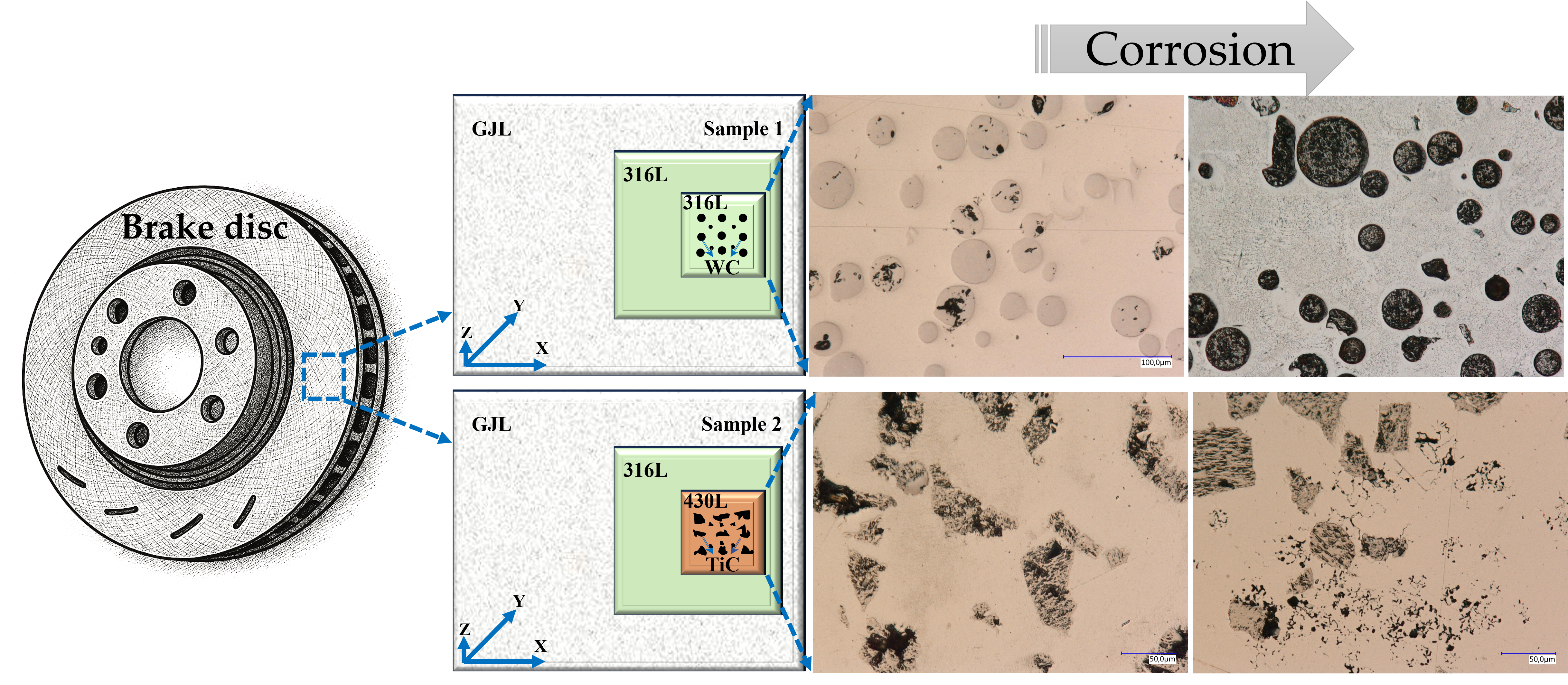
Figure 1 depicts a three-dimensional representation of the resulting CS of the samples from top view. The first layer in both systems was composed of 316L stainless steel powder (20-53 µm, max. 5% oversize/undersize), selected for its excellent corrosion resistance and mechanical properties. The second layer of the first sample was reinforced with 30 to 40 wt. % spherical WC particles (5–40 µm) embedded in a 316L matrix. The second sample used a 430L stainless steel matrix (20-53 µm, max. 5% oversize/undersize) reinforced with 30 to 40 wt. % angular TiC particles (5–50 µm). All powders were supplied in gas-atomized form and used as received.
The coatings were deposited on grey cast iron brake disc substrates using a laser metal deposition system equipped with a coaxial powder nozzle and a continuous-wave fiber laser. The process parameters (laser power, scanning speed, powder feed rate, and shielding gas flow) were optimized based on preliminary trials to ensure good metallurgical bonding and minimal dilution. The laser power was set to 20 kW.
The samples were cut from the same location and top view of the coated brake disc, then embedded in epoxy resin, ground, and polished to a final surface finish of 1 µm using diamond suspension. After polishing and prior to corrosion testing, the surface roughness (Ra values) of all samples was measured using a Zeiss profilometer. Surface roughness is a critical parameter influencing corrosion behavior, and measurements were taken to ensure consistency across samples.
As illustrated in Table 1, the chemical compositions of the used materials are presented. The chemical composition of the gas atomized powders utilized for coating the samples was provided by the supplier, Höganäs.
The samples investigated are illustrated in Table 2. The samples were separated, embedded, and polished to evaluate their microstructure. The samples were mechanically polished to 1 µm to achieve a high-quality surface finish. For each CS (316L+(316L+WC) and 316L+(430L+TiC)), three samples were prepared. Surface roughness was measured three times on each sample using a Zeiss profilometer, resulting in a total of 18 measurements.
2.2. Microstructural Characterization
The microstructure of the coatings was analyzed using optical microscopy and scanning electron microscopy (SEM ZEISS EVO MA 15) before and after corrosion test. Energy-dispersive X-ray spectroscopy (EDS) was employed to evaluate the distribution of alloying elements and hard particles within the matrix. The interface between the coating and the substrate was also examined to assess bonding quality and dilution effects.
2.3. Corrosion Testing
Electrochemical corrosion tests were conducted in accordance with DIN EN ISO 17475 [19], a standardized method that provides detailed guidelines for performing potentiostatic and potentiodynamic polarization measurements on metallic materials. This standard is particularly suitable for evaluating the electrochemical kinetics of anodic and cathodic reactions, the onset of localized corrosion, and the repassivation behavior of metallic surfaces.
In summary, DIN EN ISO 17475 was selected because it offers a comprehensive, standardized, and scientifically validated approach to assess the corrosion behavior of complex, multilayered metallic coatings in saline environments.
Potentiodynamic polarization measurements were carried out in a 5 wt.% NaCl solution at room temperature using a three-electrode configuration: the coated sample served as the working electrode, a saturated calomel electrode (SCE) as the reference electrode, and a graphite rod as the counter electrode. The exposed area of the working electrode was approximately 1.5 cm². Prior to testing, all samples were stabilized at open circuit potential (OCP) for about 120 minutes. The potential was scanned from −0.8 V to +0.8 V versus SCE at a scan rate of 1 mV·s⁻¹. The polarization resistance (Rp) was calculated using the Stern–Geary equation.
where βa and βc are the anodic and cathodic Tafel slopes, and is the corrosion current density.
Rp=βa*βc/(2.3*jcorr*(βa*βc)
2.4. Data Availability and Ethics
All data generated or analyzed during this study are available from the corresponding author upon reasonable request. No human or animal subjects were involved in this research, and therefore no ethical approval was required.
2.5. Use of Generative AI
Generative artificial intelligence was used solely for language editing and formatting support. No AI tools were used for data generation, analysis, or interpretation.
3. Results
This section presents a concise and structured overview of the experimental findings, their interpretation, and the conclusions derived from the corrosion behavior of multilayer coatings. The samples were prepared as described in Section 2, using LMD to apply multilayer coatings on grey cast iron substrates. Prior to corrosion testing, surface morphology was examined using optical and SEM, and elemental composition was analyzed via EDS. Electrochemical corrosion tests were then conducted in a 5 wt.% NaCl solution. Post-corrosion analyses included repeated SEM and EDS investigations at selected corrosion sites to assess degradation mechanisms. Each subsection of the results is supported by comparative analysis with relevant literature to contextualize the findings.
3.1. Surface Morphology
The surface morphology of the multilayer coatings was examined prior to corrosion testing using optical microscopy and scanning electron microscopy (SEM). The top surfaces of both 316L+(316L+WC) and 316L+(430L+TiC) coatings exhibited dense and continuous structures with no visible cracks or delamination. SEM images revealed a relatively uniform distribution of hard particles within the stainless steel matrices. In particular, WC particles appeared well-embedded in the 316L matrix, while TiC particles in the 430L matrix showed slightly more pronounced surface protrusions.
The surface of the 316L+(316L+WC) coating appeared smoother and more homogeneous compared to the 316L+(430L+TiC) layer, which exhibited a slightly rougher texture due to the larger size and angular shape of the TiC particles. These morphological differences are consistent with previous studies on particle-reinforced stainless steel coatings fabricated by LMD [20].
No significant porosity was observed on the surface of either coating, indicating a high-quality deposition process. The good metallurgical bonding between the layers and the substrate suggests that the LMD parameters were well-optimized.
3.2. Microstructure
The microstructure of the multilayer coatings was analyzed using light microscopy and SEM imaging at the top of the deposited clad. As shown in Figure 2, the 316L+(316L+WC) layer exhibits a dense microstructure with uniformly distributed WC particles embedded in the austenitic matrix.
In contrast, Figure 3 illustrates the 316L+(430L+TiC) layer, where TiC particles are more angular and tend to align closely, sometimes forming chain-like arrangements. No significant porosity or delamination was observed in either coating, indicating a stable deposition process via LMD. These observations are consistent with previous studies on particle-reinforced stainless steel coatings fabricated by LMD [4]. Prior to corrosion testing, EDS analysis confirmed the presence and distribution of WC and TiC particles within their respective matrices. EDS analysis will be performed before and after corrosion testing to evaluate changes in the elemental composition of selected corrosion sites in section 3.4.
Some WC and TiC particles appeared scratched or fractured due to mechanical stress during metallographic preparation, as similarly reported in previous studies on hard-particle-reinforced coatings [21,22]. Notably, the more frequent fragmentation of TiC particles may not only result from mechanical stress during metallographic preparation, but may also reflect their intrinsically lower wear resistance compared to WC. This observation is consistent with comparative studies on ceramic reinforcements, which report that WC exhibits superior hardness, toughness, and wear behavior under abrasive and impact conditions [23]. In particular, WC particles tend to maintain their integrity during mechanical processing, whereas TiC particles are more prone to microcracking and edge chipping, especially under localized stress conditions [24].
3.3. Surface Roughness
Surface roughness measurements were performed on each of the six samples (three per coating type), with three measurements taken per sample using a Zeiss profilometer.
Figure 4 illustrates the average surface roughness of both coatings, including error bars representing the standard deviation of the nine measurements per coating. The 316L+(316L+WC) coating exhibited an average surface roughness (Ra) of 0.09± 0.03 µm, while the 316L+(430L+TiC) coating showed a slightly higher roughness of 0.49 ± 0.03 µm.
These values suggest a more textured surface for the 316L+(430L+TiC) layer, potentially due to the angular morphology and distribution of TiC particles as described above.
The low standard deviations indicate a consistent surface finish after polishing, which reflects the uniformity of the post-processing rather than the intrinsic stability of the LMD process. Therefore, these values should not be interpreted as a direct measure of process stability.
Surface roughness plays a critical role in corrosion behavior, as it influences the effective surface area exposed to the corrosive medium and can promote localized corrosion initiation. Studies have shown that increased roughness may lead to higher corrosion rates due to the formation of micro-crevices and enhanced electrolyte retention [25].
3.4. Corrosion Behavior
The results revealed distinct differences in electrochemical performance between the two systems.
The electrochemical parameters discussed in this section are derived from the potentiodynamic polarization curves shown in Figure 5, which illustrate the corrosion behavior of both coating systems under identical test conditions
The 316L+(316L+WC) coating demonstrated a more noble corrosion potential () and a significantly lower corrosion current density (), indicating superior corrosion resistance. This behavior is attributed to the austenitic nature of the 316L matrix, which is known for its excellent passivation capability in chloride-containing environments [15]. Two distinct passive regions were identified in the polarization curve. The first region, between approximately −0.2 V and 0 V vs. Ag/AgCl/sat. KCl, is likely associated with WC oxidation, as tungsten-based oxides (WO₃, W₂O₅) tend to form early but are relatively unstable in chloride-containing media. These oxides are porous, soluble, and non-self-healing, resulting in a higher passive current density compared to stainless steel. This behavior can be explained by the electrochemical reaction of WC in aqueous environments, where WC undergoes oxidative dissolution according to the reaction an equation 2 [26]:
WC + 5H₂O → WO₃ + CO₂ + 10H⁺ + 10e⁻
The formation of WO₃ and release of CO₂ indicate that WC is thermodynamically unstable under acidic or chloride-containing conditions, leading to degradation of the hard particles and weakening of the composite coating.[https://www.mdpi.com/2075-4701/15/7/777]. The second region, extending from +0.2 V to +0.6 V, corresponds to the passivation of the 316L matrix through the formation of a dense Cr₂O₃-based film, supported by Fe₂O₃ and MoO₃, which provides more stable protection. The overall passive current density ranged from 10⁻⁶ to 10⁻³ A/cm², with higher values observed in the second region due to partial WC dissolution near 0 V, which reduces film compactness and promotes localized attack[27].
In contrast, the 316L+(430L+TiC) coating exhibited a more negative corrosion potential () and a significantly higher corrosion current density (), indicating a higher corrosion rate and reduced passivation compared to the 316L+WC system.
The polarization curve revealed a narrow passive region between approximately –0.5 V and 0 V vs. Ag/AgCl/sat. KCl, with a passive current density () around , indicating less stable passivation compared to CS1. The pitting potential () marks the onset of localized corrosion, likely influenced by the ferritic nature of the 430L matrix and microgalvanic interactions with TiC particles. Although TiC is chemically stable and does not undergo corrosion, its influence on the overall electrochemical behavior of the multilayer coating cannot be conclusively determined in this study, as no reference data for 430L stainless steel alone are available. Therefore, while TiC may contribute to passive film formation, the observed behavior under chloride exposure reflects the combined effect of the matrix and reinforcement rather than TiC alone.
The quantitative results of the electrochemical tests are summarized in Table 3, which includes corrosion potential (Ecorr), corrosion current density (jcorr), anodic and cathodic Tafel slopes (βa, βc), and corrosion rates. The anodic and cathodic Tafel slopes (βₐ and βc) were applied to calculate the polarization resistance (Rp) using Equation 1, as the reactions occurred in the activation-controlled region. These slopes do not directly indicate passive film formation; instead, passivation tendencies can be inferred from the corrosion current density (jcorr), Rp values, and corrosion rates. A lower jcorr combined with a higher Rp generally reflects easier passivation. Based on the averaged data, the 316L+WC coating exhibited a jcorr of ≈ 7.39 × 10⁻⁷ A/cm² and an Rp of approximately 3.2 kΩ·cm², whereas the 316L+(430L+TiC) coating showed a higher jcorr of ≈ 2.83 × 10⁻⁶ A/cm² and a lower Rp of about 0.9 kΩ·cm². This indicates that the WC-reinforced system provides superior corrosion resistance under uniform conditions. The calculated corrosion rates further support this trend, with 316L+WC at ≈ 8.58 µm/year (0.00858 mmpy) compared to ≈ 32.89 µm/year (0.03289 mmpy) for 316L+(430L+TiC). The poorer performance of the TiC-reinforced system can be attributed to localized degradation mechanisms such as pitting and microgalvanic coupling within the ferritic 430L phase, which accelerate material loss despite the presence of hard TiC particles. Additionally, the more negative Ecorr (−665 mV vs. −611 mV) for the TiC system suggests a higher thermodynamic tendency toward corrosion, reinforcing the role of microstructural heterogeneity in its electrochemical behavior [28]. Therefore, the corrosion rate alone does not contradict the overall electrochemical indicators of passivation quality, which favor the 316L+(316L+WC) system.
Chi-squared values indicate acceptable to good fit quality for both datasets. The inclusion of Tafel slopes provides insight into electrochemical kinetics, while corrosion rates offer practical relevance for material degradation. Adding the standard deviation of jcorr enhances the statistical robustness of the comparison. These results confirm the superior passivation tendency of the austenitic 316L matrix and highlight the influence of ceramic reinforcement type on the electrochemical stability of multilayer coatings.
Figure 5 presents the potentiodynamic polarization curves of the two coating systems (CS1: 316L+(316L+WC) and CS2: 316L+(430L+TiC)) measured in 5 wt.% NaCl solution. The curves reveal distinct electrochemical behaviors influenced by both matrix composition and the type of reinforcement particles. The corrosion potential () of CS1 is more noble compared to CS2, indicating a higher resistance to initial corrosion. The corrosion current density () is significantly lower for CS1 (316L+WC), indicating a slower corrosion rate and enhanced passivation compared to CS2 (316L+(430L+TiC)).
This improvement can be attributed to the austenitic 316L matrix, which generally exhibits superior corrosion resistance in chloride-containing environments. In contrast, the ferritic 430L matrix in CS2 is more prone to localized attack and galvanic interactions, which explains its higher jcorr and corrosion rate. Literature reports that Ecorr for 316L typically ranges between −100 mV and +100 mV [Corrosion Behavior of Stainless Steel in Seawater in the Presence of Sulfide], while for 430L it lies between −500 mV and −300 mV, confirming the inherent difference in corrosion behavior [IJEIR-1416_final.pdf][ Corrosion behavior of 430 ferritic stainless steel | AIP Conference Proceedings | AIP Publishing]. Although direct measurements of the individual base materials were not performed in this study, the observed shift of Ecorr for CS1 to more negative values (≈ −611 mV) suggests that the incorporation of WC particles may have influenced the electrochemical response, consistent with findings in previous studies. This negative shift does not negate the overall improvement in corrosion resistance, as indicated by the significantly lower jcorr and higher Rp for CS1. The corrosion resistance of WC-based coatings varies significantly depending on the deposition technique. According to Ward et al. (2011), HVOF-sprayed WC cermet coatings on ferritic stainless steel exhibit poor corrosion performance in salt spray environments, primarily due to high porosity, microcracks, galvanic interactions, and phase dissolution, which promote substrate degradation [29]. In contrast, Mertgenç et al. (2023) demonstrated that WC and TiC coatings applied via Electro-Spark Deposition (ESD) on high-speed steels significantly enhance both hardness and corrosion resistance. Notably, TiC coatings showed up to a threefold improvement in corrosion resistance, making them particularly suitable for applications in aggressive environments [30].
CS2 exhibits a passivation region, but the passivation current density jp is higher, indicating less stable passive film formation. The pitting potential Epit of CS2 is lower, which correlates with the presence of microgalvanic cells between 430L and TiC, leading to localized corrosion sites Similar behavior was reported by Yang and Kong (2024), who observed that TiC-reinforced Fe-based coatings produced by laser cladding showed enhanced electrochemical resistance with increasing TiC content, yet also revealed localized corrosion phenomena attributed to interfacial reactions and microstructural heterogeneity [31].
Figure 6 presents light microscopy and SEM images of the CS1 coating system (316L+(316L+WC)), highlighting the microstructural features before and after corrosion testing. The micrographs clearly illustrate the corrosion-induced degradation of the CS1 coating system (316L+(316L+WC)). Prior to corrosion, the spherical WC particles appear well-embedded within the austenitic 316L matrix, showing smooth interfaces and minimal surface irregularities. After exposure to the corrosive environment, the WC particles exhibit pronounced surface roughening and partial dissolution, indicating their susceptibility to chemical attack.
This observation supports the electrochemical findings, where CS1 showed a relatively stable passive region but also signs of localized corrosion. The matrix itself displays mild corrosion effects, particularly near the particle-matrix interfaces. These regions may correspond to areas of microgalvanic interaction, where the electrochemical potential difference between WC and the surrounding austenitic steel promotes localized degradation [32].
The corrosion behavior of the matrix may also be influenced by the austenitic grain boundary characteristics, which are known to affect passivation stability. The degradation pattern suggests that WC, despite its mechanical advantages, may compromise corrosion resistance when not uniformly protected by the passive film.
Post-corrosion SEM images reveal pronounced surface roughening and partial dissolution of WC, indicating their susceptibility to chemical attack. These findings are consistent with Huang et al. [33]. who reported partial melting and degradation of WC particles in laser-cladded coatings. Additionally, Revilla and De Graeve (2022) identified particle-matrix interfaces as critical sites for corrosion initiation, supporting the observed localized damage in CS1. [34].
In SEM Figure 7 has been shown one WC particle of CS1 coating system (316L+(316L+WC)) after corrosion testing in 5 wt.% NaCl solution. The image highlights white interfacial lines surrounding WC particles, indicating elemental diffusion during the laser deposition process. This diffusion leads to partial decomposition of WC, releasing W and C into the surrounding matrix. These elements interact with Cr from the 316L matrix, forming secondary carbides such as CrC [35]. As confirmed by EDX analysis in Masafi et al. (2023) [4], the chemical composition near fractured WC particles reveals W diffusion and the formation of intermetallic phases, most likely τ₁ (Fe₃W₃C or Fe₇W₆), within the Fe–W–C ternary system. These newly formed carbides are electrochemically more noble than the surrounding steel matrix, which promotes microgalvanic coupling and localized corrosion [32]. In addition, WC itself is thermodynamically unstable in chloride-containing environments and undergoes oxidative dissolution according to equation (2). The formation of WO₃ and release of CO₂ indicate that WC degradation is driven by electrochemical oxidation, which disrupts the passive film and creates weak points for corrosion initiation. This mechanism, combined with galvanic interactions involving τ₁-phase carbides, explains the observed localized attack near reinforcement particles and newly formed τ₁-phase regions[36].
Energy-dispersive X-ray spectroscopy (EDS) was performed at selected points on the CS1 coating system before and after corrosion testing, as shown in Figure 8 and Table 4. Spectra points S1 and S2 correspond to measurements on the matrix prior to corrosion, while S3 and S4 were taken after corrosion. The results indicate a slight but consistent reduction in Chromium (Cr) content, from approximately 17.7 % (S1–S2) to 16.5 % (S3–S4), which represents a relative decrease of about 6–7 %. Although the absolute difference appears small, such localized Cr depletion can be critical for passive film stability, particularly in stainless steels exposed to sensitization temperatures (450–850 °C), where Cr-rich carbides (Cr₂₃C₆) may form at grain boundaries. This phenomenon weakens the protective oxide layer and increases susceptibility to intergranular corrosion. While the measured Cr values remain above the critical threshold of 12 %, the observed trend supports the hypothesis of elemental redistribution and passive film disruption during corrosion. This supports the hypothesis of Cr depletion due to elemental diffusion and passive film disruption, as discussed in Figure 7.
Spectra points S5 and S6 represent measurements on WC particles prior to corrosion, while S7 and S8 were taken post-corrosion. The presence of Chlorine (Cl) and Sodium (Na) on WC particles after corrosion (e.g., S7) provides direct evidence of chloride-induced corrosion. This observation aligns with findings by Huang et al. (2023), who reported similar Cl and Na accumulation on WC surfaces after exposure to NaCl environments [37].
These results confirm that WC particles, while mechanically beneficial, are vulnerable to localized corrosion in chloride-rich environments, especially when embedded in austenitic matrices.
Figure 8.
SEM images of the CS1 coating system before (left) and after (right) corrosion testing in 5 wt.% NaCl solution. Labeled points (S1–S8) indicate locations of EDS measurements. Post-corrosion images reveal surface degradation and elemental changes, particularly Cr reduction in the matrix and Cl/Na accumulation on WC particles. *Note: The asterisk (*) next to the scale bar indicates that the scale was automatically generated by the ZEISS SEM system based on the magnification settings.
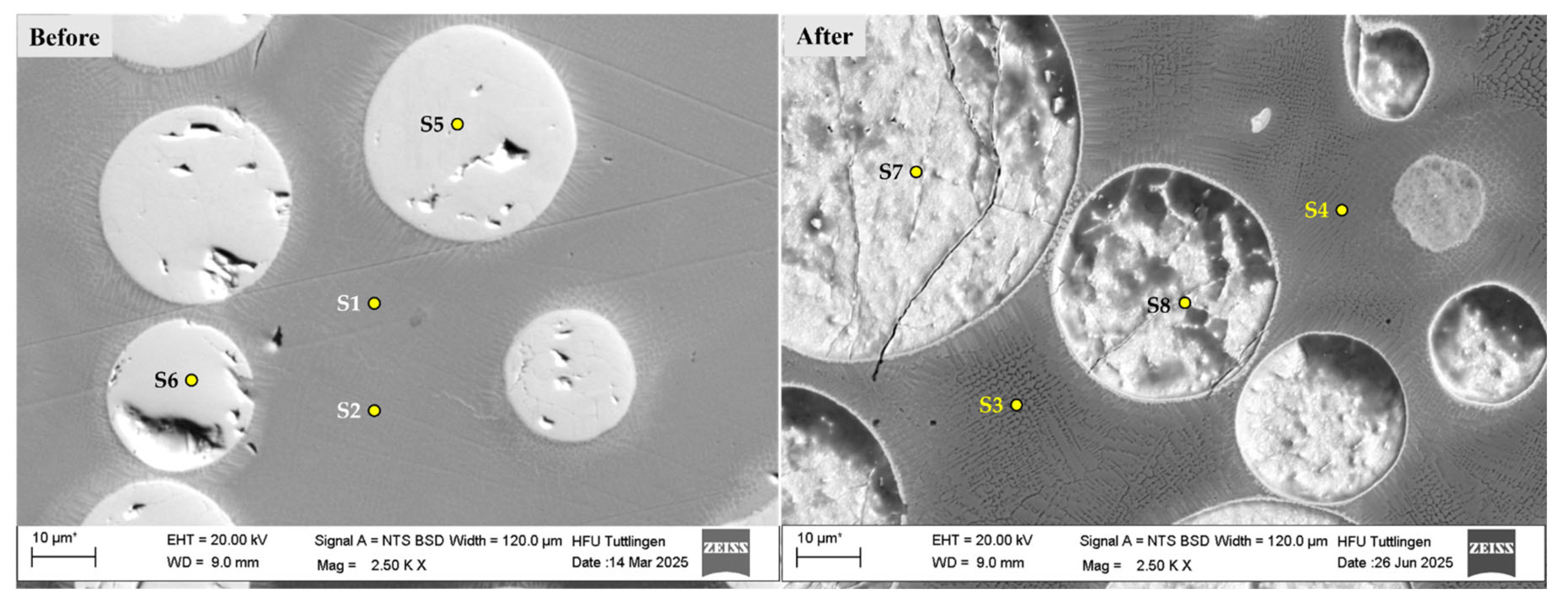

Table 4.
Atomic concentration percentages of selected elements (C, Na, S, Cl, Cr, Mn, Fe, Ni, W) at spectra points S1–S8 obtained by EDS analysis before and after corrosion testing. Notable changes include Cr depletion in the matrix and Cl/Na enrichment on WC particles.
Atomic concentration [%]
Table 4.
Atomic concentration percentages of selected elements (C, Na, S, Cl, Cr, Mn, Fe, Ni, W) at spectra points S1–S8 obtained by EDS analysis before and after corrosion testing. Notable changes include Cr depletion in the matrix and Cl/Na enrichment on WC particles.
Atomic concentration [%]
| Spectrum | C | Na | Cl | Cr | Mn | Fe | Ni | Mo | W |
| S1 | 2.156 | 0.000 | 0.000 | 17.632 | 1.110 | 65.533 | 9.471 | 1.519 | 2.579 |
| S2 | 1.781 | 0.000 | 0.000 | 17.694 | 1.178 | 65.852 | 9.447 | 1.512 | 2.536 |
| S3 | 1.588 | 0.000 | 0.000 | 16.681 | 1.181 | 67.462 | 9.739 | 1.208 | 2.141 |
| S4 | 1.552 | 0.000 | 0.000 | 16.473 | 1.216 | 67.382 | 9.915 | 1.249 | 2.214 |
| S5 | 18.449 | 0.000 | 0.000 | 0.000 | 0.000 | 0.535 | 0.081 | 0.000 | 80.936 |
| S6 | 15.694 | 0.000 | 0.000 | 0.051 | 0.087 | 0.803 | 0.620 | 0.000 | 82.745 |
| S7 | 24.595 | 0.458 | 0.253 | 0.120 | 0.000 | 0.749 | 0.205 | 0.000 | 73.620 |
| S8 | 27.738 | 0.646 | 0.690 | 0.441 | 0.000 | 0.720 | 0.261 | 0.000 | 69.504 |
Additionally, the diffusion process contributes to the partial decomposition of WC particles within the coating matrix. Under continuous-wave laser deposition conditions, secondary carbides are formed as a result of WC dissolution Ruiz-Luna et al., 2024. While this transformation may enhance local hardness and wear resistance, it can simultaneously reduce corrosion resistance due to Cr consumption and matrix destabilization. The released tungsten (W) and carbon (C) atoms interact with chromium from the 316L matrix, leading to the formation of chromium carbides such as CrC, which alter the microstructure and electrochemical behavior of the coating [38]. Secondary carbides formed in the coatings under continuous-wave mode, while partial WC dissolution improved wear resistance. These microstructural changes can influence corrosion by altering elemental distribution. EDS analysis (Table 4) indicates a slight Cr reduction after corrosion (about 6–7 % relative), consistent with early sensitization stages. This trend is consistent with sensitization phenomena in stainless steels, where thermal exposure promotes chromium carbide precipitation at grain boundaries, reducing local Cr availability for passive film formation and increasing susceptibility to corrosion. Although EDS alone does not confirm carbide precipitation, it provides supportive evidence when combined with SEM observations and thermodynamic considerations [39].
Before and after-corrosion SEM imagings (Figure 9) revealed surface degradation in coating systems 316L+(430L+TiC). In this multilayer system, more pronounced damage was observed, including localized features resembling pitting corrosion. These features are likely caused by microgalvanic interactions between the ferritic 430L matrix and the TiC particles, which exhibit significant differences in electrochemical potential. The observed pitting corrosion in CS2 may be attributed to chromium depletion at grain boundaries, as ferritic stainless steels like 430L are known to form some carbides under thermal exposure, which locally reduce corrosion resistance [40]. The incorporation of TiC particles in the 430L matrix promotes acicular ferrite formation and grain refinement, which can improve mechanical stability. Nevertheless, the potential for microgalvanic interactions between TiC and the ferritic matrix may contribute to localized corrosion phenomena [41].
Figure 10 shows the microstructural characteristics of the 430L+TiC coating system after corrosion testing. The SEM images reveal localized pits predominantly in the ferritic matrix, but these pits frequently occur in close proximity to TiC particles, as highlighted in the low-magnification image. This spatial correlation suggests that microgalvanic effects cannot be fully excluded, even if TiC particles themselves remain intact due to their higher corrosion resistance. Literature reports indicate that during LMD processing, partial Ti diffusion from TiC can lead to the formation of fine eutectic phases near the matrix–particle interface, which may locally alter electrochemical behavior [42]. Such interfaces could act as preferential sites for corrosion initiation, consistent with the observed pit distribution.
The schematic diagram (right) complements the SEM findings by highlighting areas of material loss and corrosion product accumulation. The dashed orange line marks the clear surface of the schematic representation on the right and indicates damage caused by corrosion-related deterioration. Yellow-highlighted zones show regions affected by corrosion, while the blue arrows point to filled areas, suggesting partial re-deposition or accumulation of corrosion products, including localized pitting.
This combined visualization supports the interpretation of corrosion mechanisms and the microstructural evolution within the coating system, emphasizing the role of TiC particles in both electrochemical behavior and surface stability.
Figure 10.
SEM image (left) and schematic diagram (right) of the 430L+TiC coating system after corrosion testing. The SEM image reveals cavities and pitting corrosion, indicating localized corrosion likely caused by microgalvanic interactions between the ferritic 430L matrix and TiC particles. The schematic highlights areas of material loss and corrosion product accumulation. The dashed orange line marks the original surface level, while yellow-highlighted zones indicate corrosion-affected regions. Blue arrows point to filled areas, suggesting partial re-deposition or accumulation of corrosion products, including localized pitting. *Note: The asterisk (*) next to the scale bar indicates that the scale was automatically generated by the ZEISS SEM system based on the magnification settings.
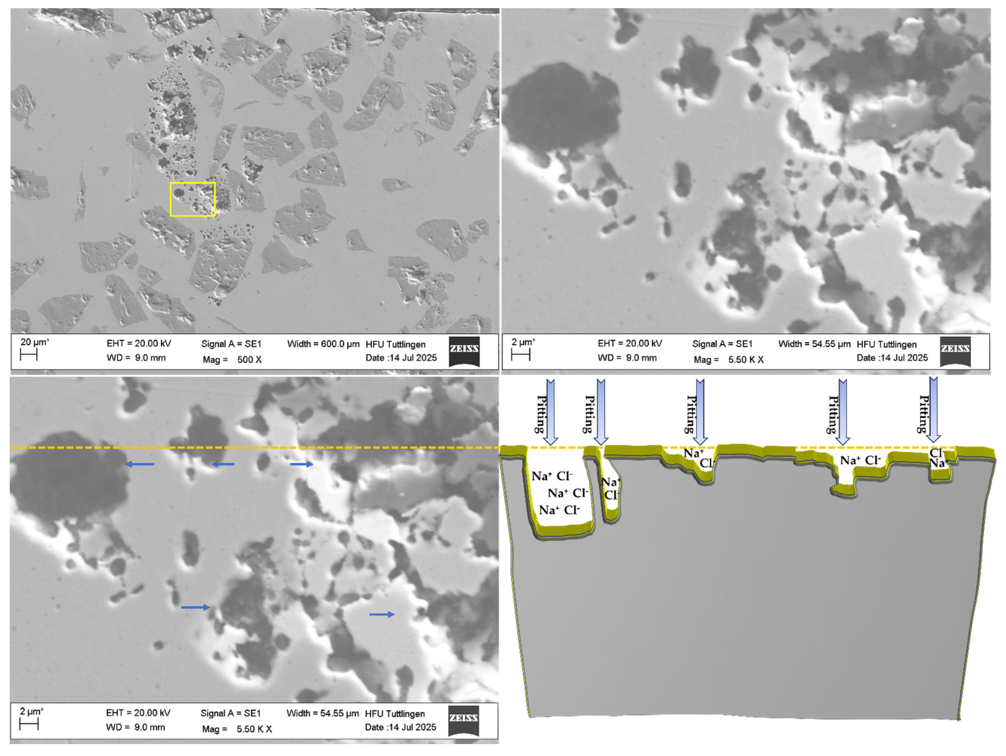
Figure 11 and Table 5 present the EDS analysis results of the 430L+TiC coating system before(left) and after(right) corrosion testing. The SEM micrographs in Figure 11 show the surface region at low magnification, with marked points (S1–S8) indicating the locations of EDS measurements.
Table 5 summarizes the atomic concentrations of key elements at these points. Notably, Spectra S1 and S2 (before corrosion) with compare S6, S7 and S8 show reveal increased levels of sodium (Na) and chlorine (Cl), indicating the accumulation of corrosion products, likely from the NaCl test environment [43]. A significant observation is the reduction in chromium (Cr) concentration at corroded sites (e.g.,S6, S7and S8), supporting the hypothesis of chromium depletion due to localized corrosion and microgalvanic interactions especially along grain boundaries or in the vicinity of TiC particles [44]. Spectra S2 measuring point, which means that Ti was dissolved from TiC and diffused in the 430L matrix during laser metal deposit. This measurement proves that Ti diffuses from TiC. The formed intermetallic phase is most likely TiC in iron-containing matrix materials [4]. However, a comparison of the TiC before and after corrosion demonstrates the stability of the TiC. Spectra S3 elevated carbon content (~18 %) and Ti content, consistent with the presence of TiC particles. After corrosion, Spectra S4 and S5 shows that presence of Ti remains relatively stable. The absence of a significant change in TiC composition indicates chemical stability even after corrosion exposure.
Post-corrosion SEM imaging revealed surface degradation in both coating systems. In the 316L+(430L+TiC) system, more pronounced damage was observed, including localized features resembling pitting corrosion, likely caused by microgalvanic interactions between the ferritic 430L matrix and the TiC particles. EDS analysis performed before and after corrosion testing revealed localized elemental variations at selected corrosion sites, such as slight Cr depletion and chloride enrichment, which support the electrochemical findings. Notably, TiC particles remained chemically stable after corrosion testing, showing no visible degradation in SEM images. Their stability suggests that TiC does not act as an active corrosion site, which is consistent with its known high corrosion resistance. However, a direct comparison with the substrate would be required to quantify any contribution to passive film formation. In contrast, WC particles in the 316L+(316L+WC) system showed signs of degradation, particularly at the particle–matrix interface, indicating susceptibility to corrosion despite the overall stability of the austenitic matrix [45].
4. Discussion
The comparative corrosion performance of the multilayer coating systems—316L+(316L+WC) (CS1) and 316L+(430L+TiC) (CS2)—reveals distinct electrochemical and microstructural behaviors, primarily governed by matrix composition, ceramic reinforcement, and surface characteristics.
- Influence of Matrix Composition
CS1 demonstrates superior corrosion resistance due to the austenitic nature of the 316L matrix, which forms a stable passive film in chloride environments. This aligns with literature reporting that 316L stainless steel maintains passivity under aggressive conditions owing to its chromium-rich oxide layer [46]. In contrast, CS2 incorporates ferritic 430L, which exhibits a more negative corrosion potential and higher current density, indicating reduced passivation. Ferritic stainless steels are more prone to chromium depletion and intergranular corrosion, particularly under thermal exposure or chloride attack [47].
- Role of Ceramic Reinforcements
WC particles in CS1 enhance mechanical strength but show partial dissolution and elemental redistribution after corrosion, which may disrupt passive film integrity through secondary carbide formation [Ruiz-Luna et al., 2024; Springer]. TiC particles in CS2, on the other hand, remain chemically stable and may assist in passive film formation, as TiO₂ formation can enhance chromia adhesion [48]. However, TiC also introduces microgalvanic effects when embedded in ferritic matrices. Studies show that TiC particles can act as cathodic sites, accelerating localized corrosion in the surrounding matrix [49]. This explains the observed pitting and filler accumulation in CS2, despite the chemical stability of TiC itself. TiC particles in CS2 remain chemically stable and do not exhibit visible degradation in SEM images. However, corrosion pits frequently occur near TiC inclusions, suggesting local electrochemical heterogeneity. Literature indicates that Ti diffusion from TiC during LMD can lead to eutectic phase formation at the matrix–particle interface , potentially altering local corrosion behavior [50]. While TiC itself is highly corrosion-resistant, these interfaces may act as preferential sites for pitting initiation.
- Surface Roughness and Corrosion
The higher surface roughness of CS2 (Ra ≈ 0.49 µm) compared to CS1 (Ra ≈ 0.09 µm) increases the effective surface area and promotes electrolyte retention, which can enhance localized corrosion [51]. This correlates with the broader but less stable passive region observed in CS2 [52].
- Localized Elemental Variations
EDS analysis revealed slight but consistent Cr depletion (≈6–7 % relative) at corroded sites in CS2, particularly near grain boundaries and TiC particles, supporting the hypothesis of sensitization and passive film disruption [53]. hloride enrichment detected in pits further confirms localized attack, while WC surfaces in CS1 also showed Na and Cl presence, indicating chloride-induced corrosion [54]. Although these changes do not alter the overall composition, they highlight local redistribution critical for corrosion initiation.
- Overall Interpretation
Although CS2 exhibited a lower calculated average corrosion rate, this parameter does not fully reflect localized degradation mechanisms such as pitting and interface-driven attack. Electrochemical indicators, including corrosion potential, current density, and passive film stability—consistently favor CS1. Therefore, coatings based on 316L with WC reinforcement provide more reliable corrosion protection under chloride exposure [55]. In contrast, 430L+TiC systems, despite the inherent chemical stability of TiC particles, are more susceptible to localized corrosion due to matrix sensitization and microstructural heterogeneity at particle–matrix interfaces [56,57].
5. Conclusions
This study examined the corrosion behavior of multilayer coatings composed of 316L and 430L stainless steel matrices reinforced with WC and TiC particles, fabricated via laser metal deposition on grey cast iron substrates. The results demonstrate that both matrix composition and ceramic reinforcement type significantly affect electrochemical stability and localized corrosion mechanisms.
The 316L+(316L+WC) system (CS1) exhibited superior corrosion resistance, characterized by a more noble corrosion potential and lower current density. This performance is primarily attributed to the austenitic nature of the 316L matrix, which promotes stable passivation in chloride environments. However, post-corrosion analysis revealed partial WC degradation and elemental redistribution, indicating that long-term stability may be compromised under aggressive conditions. Polarization analysis revealed two distinct passive regions: an initial region likely associated with WC oxidation and a second region corresponding to the formation of a Cr-rich passive layer on the 316L matrix. This highlights the combined influence of reinforcement and matrix composition on passivation behavior
In contrast, the 316L+(430L+TiC) system (CS2) showed higher susceptibility to localized corrosion, including pitting near TiC particles and grain boundaries. While TiC remained chemically stable and did not exhibit visible degradation, its presence may influence local electrochemical behavior through interface effects, as supported by literature on Ti diffusion and eutectic phase formation during LMD. The ferritic 430L matrix demonstrated reduced passivation efficiency and slight chromium depletion at corroded sites, confirming its lower corrosion resistance in chloride-rich environments.
Surface roughness also played a critical role: CS2 exhibited a significantly higher Ra value than CS1, promoting electrolyte retention and micro-crevice formation, which accelerate localized attack. EDS analysis further revealed localized elemental variations—such as minor Cr depletion and chloride enrichment—rather than bulk composition changes, supporting the proposed corrosion mechanisms.
Overall, 316L+WC coatings provide better global corrosion protection, whereas 430L+TiC systems, despite the inherent stability of TiC, are more vulnerable due to matrix sensitization and interface-driven effects. These findings highlight the importance of optimizing both matrix selection and reinforcement distribution to enhance the durability of LMD-fabricated coatings in chloride environments.
Author Contributions
This research article is written by several authors with the following contributions: Conceptualization, M.M.; Methodology, M.M.; Validation, M.M., M.L., H.P. and H.M.-J.; Formal analysis, M.M. and M.L.; Investigation, M.M. and M.L.; Resources, M.M., M.L., H.P. and H.M.-J.; Data curation, M.M. and M.L.; Writing—original draft preparation, M.M.; Writing—review and editing, M.M., M.L., H.P. and H.M.-J.; Visualization, M.M. and M.L.; Supervision, H.P. and H.M.-J.; Project administration, M.M., H.P. and H.M.-J.; Funding acquisition, M.M. All authors have read and agreed to the published version of the manuscript.
Funding
This research received no external funding.
Institutional Review Board Statement
Not applicable.
Informed Consent Statement
Not applicable.
Data Availability Statement
All required data in this article have only been published here and should be considered with respect to copyright.
Conflicts of Interest
The authors declare no conflicts of interest.
References
- Masafi, M.; Palkowski, H.; Mozaffari-Jovein, H. Micro-Friction Mechanism Characterization of Particle-Reinforced Multilayer Systems of 316L and 430L Alloys on Grey Cast Iron. Journal of Materials Research and Technology 2024, 33, 6090–6101. [CrossRef]
- Collini, L.; Nicoletto, G.; Konečná, R. Microstructure and Mechanical Properties of Pearlitic Gray Cast Iron. Materials Science and Engineering: A 2008, 488, 529–539. [CrossRef]
- Masafi, M.; Conzelmann, A.; Palkowski, H.; Mozaffari-Jovein, H. Microstructure Development of a Functionalized Multilayer Coating System of 316L Austenitic Steel on Grey Cast Iron Under Braking Force in a Corrosive Environment. Coatings 2025, 15, 1106. [CrossRef]
- Masafi, M.; Palkowski, H.; Mozaffari-Jovein, H. Microstructural Properties of Particle-Reinforced Multilayer Systems of 316L and 430L Alloys on Gray Cast Iron. Coatings 2023, 13, 1450. [CrossRef]
- Maluf, O.; Aparecido, J.; Angeloni, M.; Antonio, M.; Carlos, J.; Bose Filho, W.W.; Spinelli, D. Thermomechanical and Isothermal Fatigue Behavior of Gray Cast Iron for Automotive Brake Discs. In New Trends and Developments in Automotive System Engineering; InTech, 2011.
- Cho, M.H.; Kim, S.J.; Basch, R.H.; Fash, J.W.; Jang, H. Tribological Study of Gray Cast Iron with Automotive Brake Linings: The Effect of Rotor Microstructure. Tribol Int 2003, 36, 537–545. [CrossRef]
- Feo, M.L.; Torre, M.; Tratzi, P.; Battistelli, F.; Tomassetti, L.; Petracchini, F.; Guerriero, E.; Paolini, V. Laboratory and On-Road Testing for Brake Wear Particle Emissions: A Review. Environmental Science and Pollution Research 2023, 30, 100282–100300. [CrossRef]
- Grigoratos, T.; Martini, G. Brake Wear Particle Emissions: A Review. Environmental Science and Pollution Research 2015, 22, 2491–2504. [CrossRef]
- 2022; 9. European Environment Agency Air Quality in Europe ; 2022;
- Feißel, T.; Hesse, D.; Augustin, M.; Carl, D.; Kneisel, M.; Ritter, C. Regulation of Brake Particle Emissions by Euro 7 - Requirements and Trends in Future Chassis Development. In; 2025; pp. 51–68.
- Athanassiou, N.; Olofsson, U.; Wahlström, J.; Dizdar, S. Simulation of Thermal and Mechanical Performance of Laser Cladded Disc Brake Rotors. Proceedings of the Institution of Mechanical Engineers, Part J: Journal of Engineering Tribology 2022, 236, 3–14. [CrossRef]
- Toyserkani, E.; Khajepour, A.; Corbin, S.F. Laser Cladding; CRC Press, 2004; ISBN 9780429121890.
- Steen, W.M.; Mazumder, J. Laser Material Processing; Springer London: London, 2010; ISBN 978-1-84996-061-8.
- Pinkerton, A.J. Laser Direct Metal Deposition: Theory and Applications in Manufacturing and Maintenance. In Advances in Laser Materials Processing; Elsevier, 2010; pp. 461–491.
- Sedriks, A.J. Corrosion of Stainless Steels; John Wiley & Sons., 1996;
- J.R. Davis ASM Specialty Handbook: Stainless Steels; J.R. Davis, Ed.; ASM International, 1994; ISBN 978-0-87170-503-7.
- Song, G.M.; Zhou, Y.; Wang, Y.J. The Microstructure and Elevated Temperature Strength of Tungsten-Titanium Carbide Composite. J Mater Sci 2002, 37, 3541–3548. [CrossRef]
- Li, J.; Zhang, H.; Zhang, J.; Wang, M.; Jiao, Y.; Du, S.; Liu, E.; Cai, H.; Du, H.; Xu, S.; et al. TiC-Reinforced Austenitic Stainless Steel Laser Cladding Layer on 27SiMn Steel Surface: A Comparative Study of Microstructure, Corrosion, Hardness, and Wear Performance. J Mater Eng Perform 2024. [CrossRef]
- DIN EN ISO 17475:2008-07, Korrosion von Metallen Und Legierungen_- Elektrochemische Prüfverfahren_- Leitfaden Für Die Durchführung Potentiostatischer Und Potentiodynamischer Polarisationsmessungen (ISO_17475:2005+Cor._1:2006); Deutsche Fassung EN_ISO_17475:2008 2008.
- Shen, B.; Du, B.; Wang, M.; Xiao, N.; Xu, Y.; Hao, S. Comparison on Microstructure and Properties of Stainless Steel Layer Formed by Extreme High-Speed and Conventional Laser Melting Deposition. Front Mater 2019, 6. [CrossRef]
- Kim, S.H.; Obulan Subramanian, G.; Kim, C.; Jang, C.; Park, K.M. Surface Modification of Austenitic Stainless Steel for Corrosion Resistance in High Temperature Supercritical-Carbon Dioxide Environment. Surf Coat Technol 2018, 349, 415–425. [CrossRef]
- Xi, S.; Chen, H.; Zhou, J.; Zheng, L.; Wang, W.; Zheng, Q. Microstructure Evolution and Wear Resistance of a Novel Ceramic Particle-Reinforced High-Entropy Alloy Prepared by Laser Powder Bed Fusion. Ceram Int 2024, 50, 5962–5973. [CrossRef]
- Gopal S. Upadhyaya Cemented Tungsten Carbides; 1998; ISBN 978-0-8155-1417-6.
- Li, S.; Huang, K.; Zhang, Z.; Zheng, C.; Li, M.; Wang, L.; Wu, K.; Tan, H.; Yi, X. Wear Mechanisms and Micro-Evaluation of WC + TiC Particle-Reinforced Ni-Based Composite Coatings Fabricated by Laser Cladding. Mater Charact 2023, 197, 112699. [CrossRef]
- Leban, M.B.; Mikyška, Č.; Kosec, T.; Markoli, B.; Kovač, J. The Effect of Surface Roughness on the Corrosion Properties of Type AISI 304 Stainless Steel in Diluted NaCl and Urban Rain Solution. J Mater Eng Perform 2014, 23, 1695–1702. [CrossRef]
- Han, B.; Dong, W.; Fan, B.; Zhu, S. Comparison on the Immersion Corrosion and Electrochemical Corrosion Resistance of WC–Al 2 O 3 Composites and WC–Co Cemented Carbide in NaCl Solution. RSC Adv 2021, 11, 22495–22507. [CrossRef]
- Philippe Marcus Corrosion Mechanisms in Theory and Practice; Marcus, P., Ed.; CRC Press, 2011; ISBN 9780429143564.
- Han, Y.; Zhang, W.; Sun, S.; Chen, H.; Ran, X. Microstructure, Hardness, and Corrosion Behavior of TiC-Duplex Stainless Steel Composites Fabricated by Spark Plasma Sintering. J Mater Eng Perform 2017, 26, 4056–4063. [CrossRef]
- Ward, L.P.; Hinton, B.; Gerrard, D.; Short, K. Corrosion Behaviour of Modified HVOF Sprayed WC Based Cermet Coatings on Stainless Steel. Journal of Minerals and Materials Characterization and Engineering 2011, 10, 989–1005. [CrossRef]
- Mertgenç, E. Wear and Corrosion Behavior of TiC and WC Coatings Deposited on High-Speed Steels by Electro-Spark Deposition. Open Chem 2023, 21. [CrossRef]
- Haoming, Y.; Dejun, K. Microstructure, Corrosive-Wear and Electrochemical Properties of TiC Reinforced Fe30 Coatings by Laser Cladding. J Mater Eng Perform 2025, 34, 7345–7355. [CrossRef]
- Zeng, X.; Wang, R.; Tian, X.; Liu, Y. Corrosion Resistance Mechanism in WC/FeCrNi Composites: Decoupling the Role of Spherical Versus Angular WC Morphologies. Metals (Basel) 2025, 15, 777. [CrossRef]
- Huang, J.; Zhu, Z.; Wang, H.; Li, K.; Shi, W.; Jiao, T. Effect of WC Content on Microstructure and Properties of CoCrFeNi HEA Composite Coating on 316L Surface via Laser Cladding. Materials 2023, 16, 2706. [CrossRef]
- Revilla, R.I.; De Graeve, I. Microstructural Features, Defects, and Corrosion Behaviour of 316L Stainless Steel Clads Deposited on Wrought Material by Powder- and Laser-Based Direct Energy Deposition with Relevance to Repair Applications. Materials 2022, 15, 7181. [CrossRef]
- Huang, J.; Zhu, Z.; Wang, H.; Li, K.; Shi, W.; Jiao, T. Effect of WC Content on Microstructure and Properties of CoCrFeNi HEA Composite Coating on 316L Surface via Laser Cladding. Materials 2023, 16, 2706. [CrossRef]
- Pollock, C.B.; Stadelmaier, H.H. The Eta Carbides in the Fe−W−C and Co−W−C Systems. Metallurgical Transactions 1970, 1, 767–770. [CrossRef]
- Huang, J.; Zhu, Z.; Wang, H.; Li, K.; Shi, W.; Jiao, T. Effect of WC Content on Microstructure and Properties of CoCrFeNi HEA Composite Coating on 316L Surface via Laser Cladding. Materials 2023, 16, 2706. [CrossRef]
- Ruiz-Luna, H.; Cuevas-Mercado, C.E.; Félix-Martínez, C.; González-Carmona, J.M.; Ruiz-Ornelas, J.; Alvarado-Orozco, J.M. Co-Based and Co/WC Laser Metal Deposition: A Comparative Study between Continuous and Pulsed Wave Laser Process Conditions. Lasers in Manufacturing and Materials Processing 2024, 11, 447–468. [CrossRef]
- Advani, A.H.; Atteridge, D.G.; Murr, L.E.; Bruemmer, S.M.; Chelakara, R. Deformation Effects on Chromium Diffusivity and Grain Boundary Chromium Depletion Development in Type 316 Stainless Steels. Scripta Metallurgica et Materialia 1991, 25, 461–465. [CrossRef]
- Paroni, A.S.M.; Alonso-Falleiros, N.; Magnabosco, R. Sensitization and Pitting Corrosion Resistance of Ferritic Stainless Steel Aged at 800 °C. Corrosion 2006, 62, 1039–1046. [CrossRef]
- Li, Y.; Du, P.; Jiang, Z.; Yao, C.; Bai, L.; Wang, Q.; Xu, G.; Chen, C.; Zhang, L.; Li, H. Effects of TiC on the Microstructure and Formation of Acicular Ferrite in Ferritic Stainless Steel. International Journal of Minerals, Metallurgy and Materials 2019, 26, 1385–1395. [CrossRef]
- Li, J.; Zhang, H.; Zhang, J.; Wang, M.; Jiao, Y.; Du, S.; Liu, E.; Cai, H.; Du, H.; Xu, S.; et al. TiC-Reinforced Austenitic Stainless Steel Laser Cladding Layer on 27SiMn Steel Surface: A Comparative Study of Microstructure, Corrosion, Hardness, and Wear Performance. J Mater Eng Perform 2025, 34, 13318–13328. [CrossRef]
- Loto, R.T. Electrochemical Corrosion Characteristics of 439 Ferritic, 301 Austenitic, S32101 Duplex and 420 Martensitic Stainless Steel in Sulfuric Acid/NaCl Solution. J Bio Tribocorros 2017, 3, 24. [CrossRef]
- Yin, Y.; Faulkner, R.G.; Moreton, P.; Armson, I.; Coyle, P. Grain Boundary Chromium Depletion in Austenitic Alloys. J Mater Sci 2010, 45, 5872–5882. [CrossRef]
- Olsson, C.-O.A.; Landolt, D. Passive Films on Stainless Steels—Chemistry, Structure and Growth. Electrochim Acta 2003, 48, 1093–1104. [CrossRef]
- Albrimi, Y.A.; Eddib, A.; Douch, J.; Berghoute, Y.; Hamdani, M.; Souto, R.M. Electrochemical Behaviour of AISI 316 Austenitic Stainless Steel in Acidic Media Containing Chloride Ions; 2011; Vol. 6;.
- Sommer, N.; Warres, C.; Lutz, T.; Kahlmeyer, M.; Böhm, S. Transmission Electron Microscopy Study on the Precipitation Behaviors of Laser-Welded Ferritic Stainless Steels and Their Implications on Intergranular Corrosion Resistance. Metals (Basel) 2022, 12, 86. [CrossRef]
- Wu, Q.; Xu, Y.; Zhang, J.; Zhong, N.; Fan, C.; Chang, X.; Zhang, X. Corrosion Behaviour of TiC Particle-Reinforced 304 Stainless Steel in Simulated Marine Environment at 650 °C. ISIJ International 2019, 59, 336–344. [CrossRef]
- Han, Y.; Zhang, W.; Sun, S.; Chen, H.; Ran, X. Microstructure, Hardness, and Corrosion Behavior of TiC-Duplex Stainless Steel Composites Fabricated by Spark Plasma Sintering. J Mater Eng Perform 2017, 26, 4056–4063. [CrossRef]
- Li, J.; Zhang, H.; Zhang, J.; Wang, M.; Jiao, Y.; Du, S.; Liu, E.; Cai, H.; Du, H.; Xu, S.; et al. TiC-Reinforced Austenitic Stainless Steel Laser Cladding Layer on 27SiMn Steel Surface: A Comparative Study of Microstructure, Corrosion, Hardness, and Wear Performance. J Mater Eng Perform 2025, 34, 13318–13328. [CrossRef]
- Hagen, C.M.H.; Hognestad, A.; Knudsen, O.Ø.; Sørby, K. The Effect of Surface Roughness on Corrosion Resistance of Machined and Epoxy Coated Steel. Prog Org Coat 2019, 130, 17–23. [CrossRef]
- Hagen, C.M.H.; Hognestad, A.; Knudsen, O.Ø.; Sørby, K. The Effect of Surface Roughness on Corrosion Resistance of Machined and Epoxy Coated Steel. Prog Org Coat 2019, 130, 17–23. [CrossRef]
- Ma, C.; Zhang, X.; Liu, T.; Ren, P.; Liu, Y.; Shoji, T. Effects of Sensitization on Intergranular Corrosion and Mechanical Properties of 316LN Stainless Steel. Journal of Nuclear Materials 2025, 615, 155925. [CrossRef]
- Popoola, A.P.I. Hardness, Microstructure and Corrosion Behaviour of WC-9Co-4Cr+TiC Reinforced Stainless Steel. Int J Electrochem Sci 2014, 9, 1273–1285. [CrossRef]
- Ziqiang, P.; Kaiping, D.; Xing, C.; Zhaoran, Z.; Chen, W. Investigation of the Dissolution-Precipitation Behavior and Properties of High-Speed Laser Cladding WC/316L Composite Coatings. Sci Rep 2025, 15, 17564. [CrossRef]
- Loto, R.T.; Oladipupo, S.; Folarin, T.; Okosun, E. Impact of Chloride Concentrations on the Electrochemical Performance and Corrosion Resistance of Austenitic and Ferritic Stainless Steels in Acidic Chloride Media. Discover Applied Sciences 2025, 7, 672. [CrossRef]
- Yazdani, S.; Tekeli, S.; Rabieifar, H.; Akbarzadeh, E. Fracture and Wear Behavior of Functionally Graded 316L–TiC Composite Fabricated by Selective Laser Melting Additive Manufacturing. Steel Res Int 2024, 95. [CrossRef]
Figure 1.
The production of the sample is shown schematically in three dimensions from a top view and Cross-section view. Two coatings are applied to the substrate: Sample 1: 316L, followed by 316L with spherical hard particles of WC, and Sample 2: 316L, followed by 430L with asymmetrical hard particles of TiC. The two coating layers are referred to as the first layer direct on substrate GJL and second layer direct on first Layer, respectively.
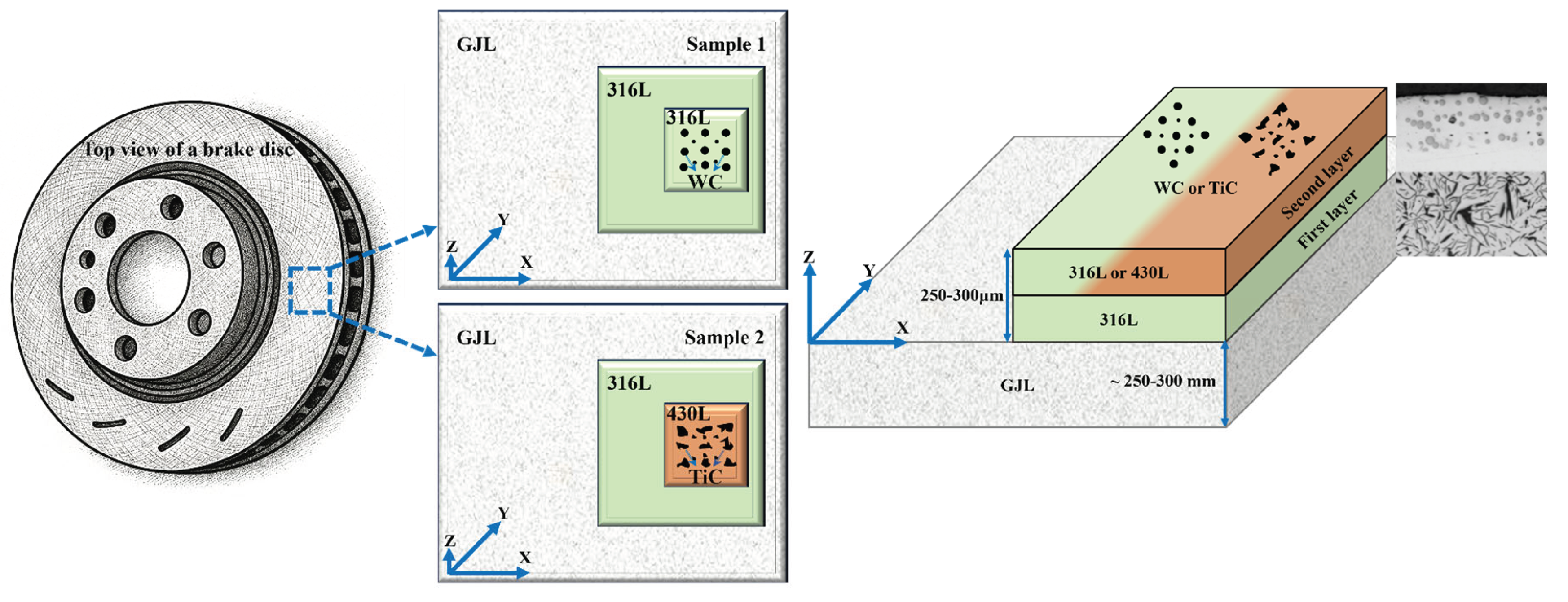
Figure 2.
Top-view light (left) and SEM (right) image of the 316L+(316L+WC) coating layer of first sample showing a dense microstructure with uniformly distributed WC particles embedded in the austenitic 316L matrix. Some WC particles appear scratched due to mechanical stress during metallographic preparation.
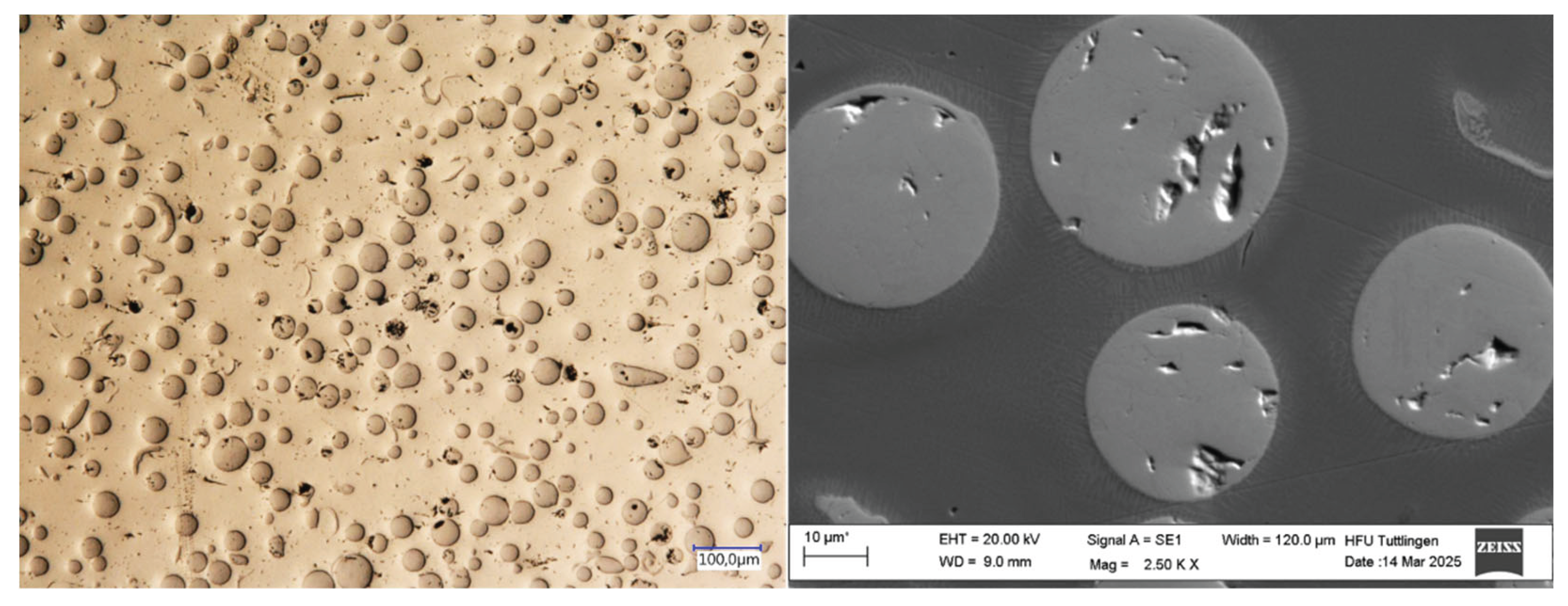
Figure 3.
Top-view light (left) and SEM (right) image of the 316L+(430L+TiC) coating layer showing a dense microstructure with angular TiC particles aligned closely, occasionally forming chain-like structures within the ferritic 430L matrix. Some TiC particles broke due to mechanical stress during metallographic preparation.
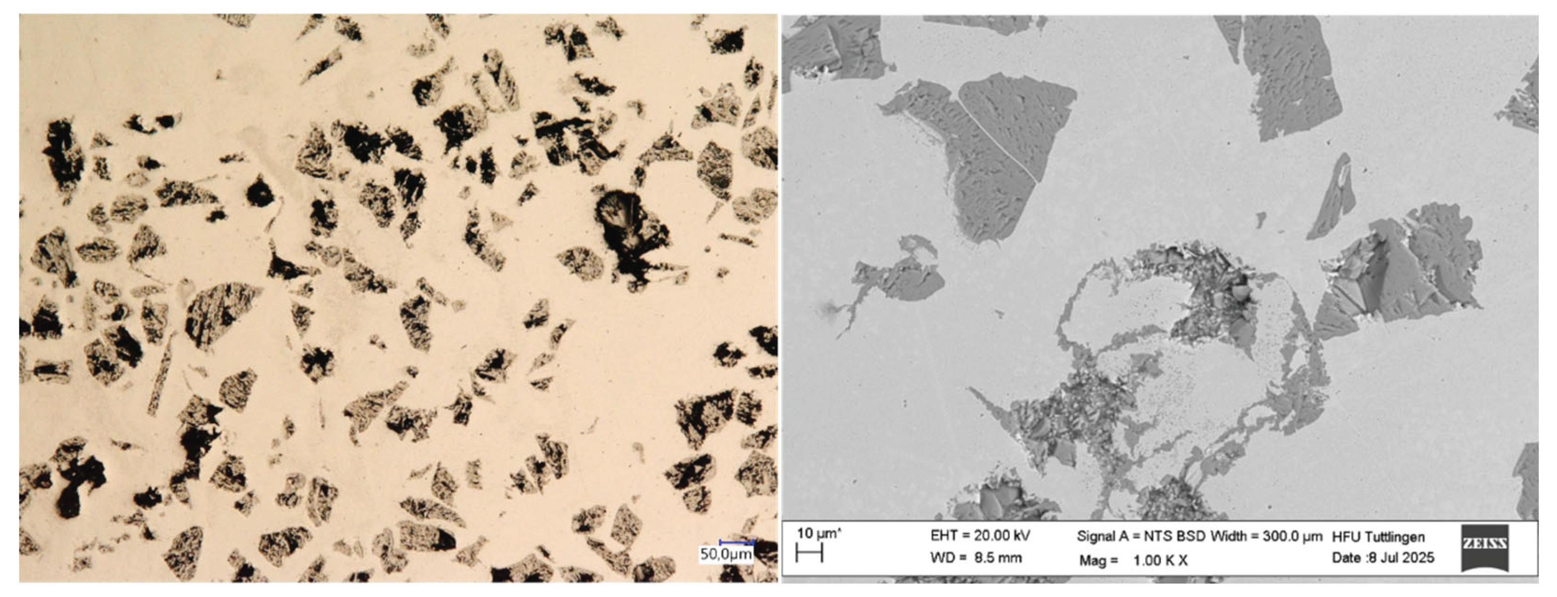
Figure 4.
Average surface roughness (Ra) of the multilayer coatings, measured on three samples per coating type, with three measurements per sample. Error bars indicate the standard deviation of nine measurements per coating. The 316L+(430L+TiC) coating exhibits slightly higher roughness compared to the 316L+(316L+WC) coating, suggesting a more textured surface morphology due to the angular nature of TiC particles.
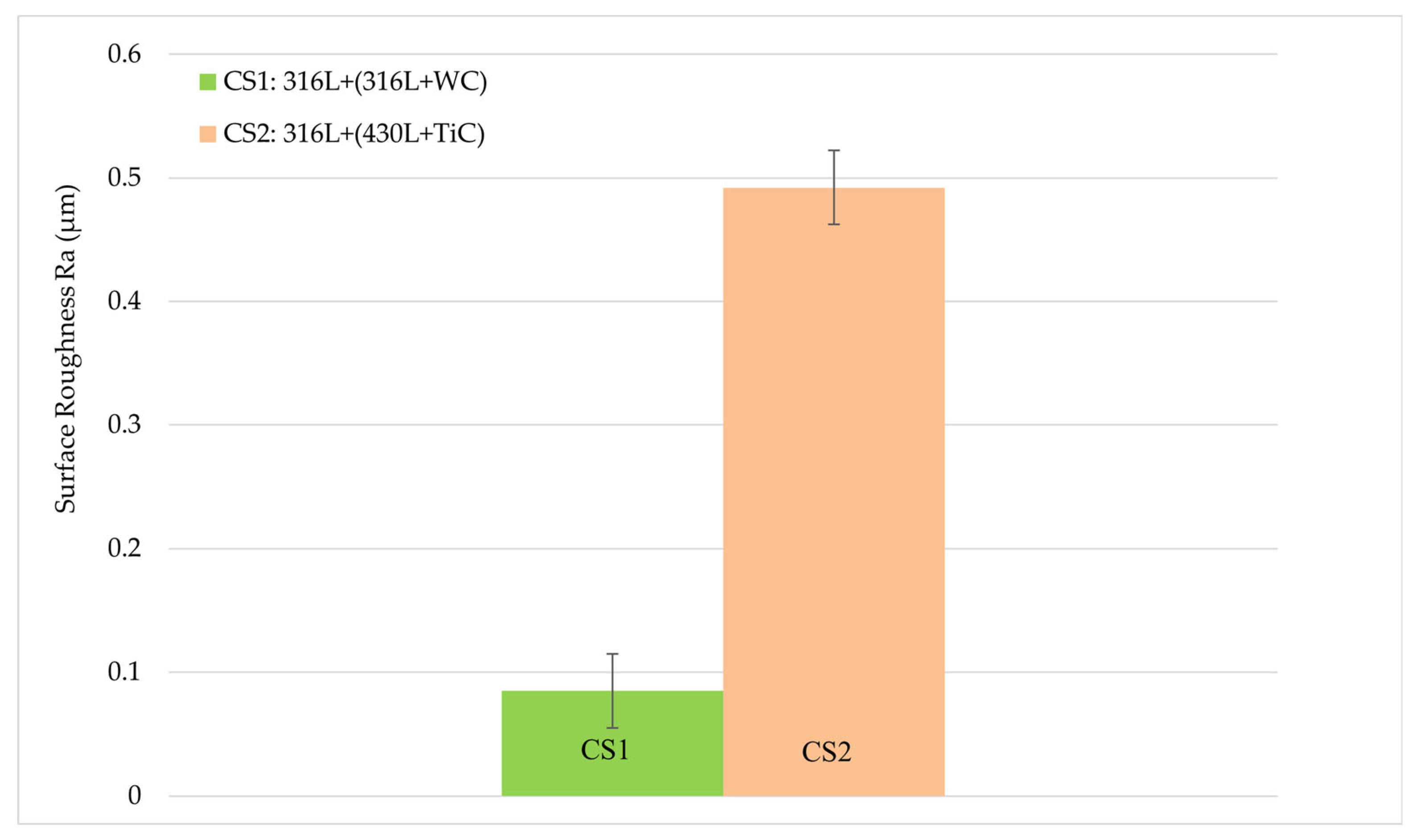
Figure 5.
Potentiodynamic polarization curves of the multilayer coating systems 316L+(316L+WC) (CS1) and 316L+(430L+TiC) (CS2) measured in 5 wt.% NaCl solution. Each curve represents the average of three independent measurements per system. Key electrochemical parameters are highlighted, including corrosion potential (
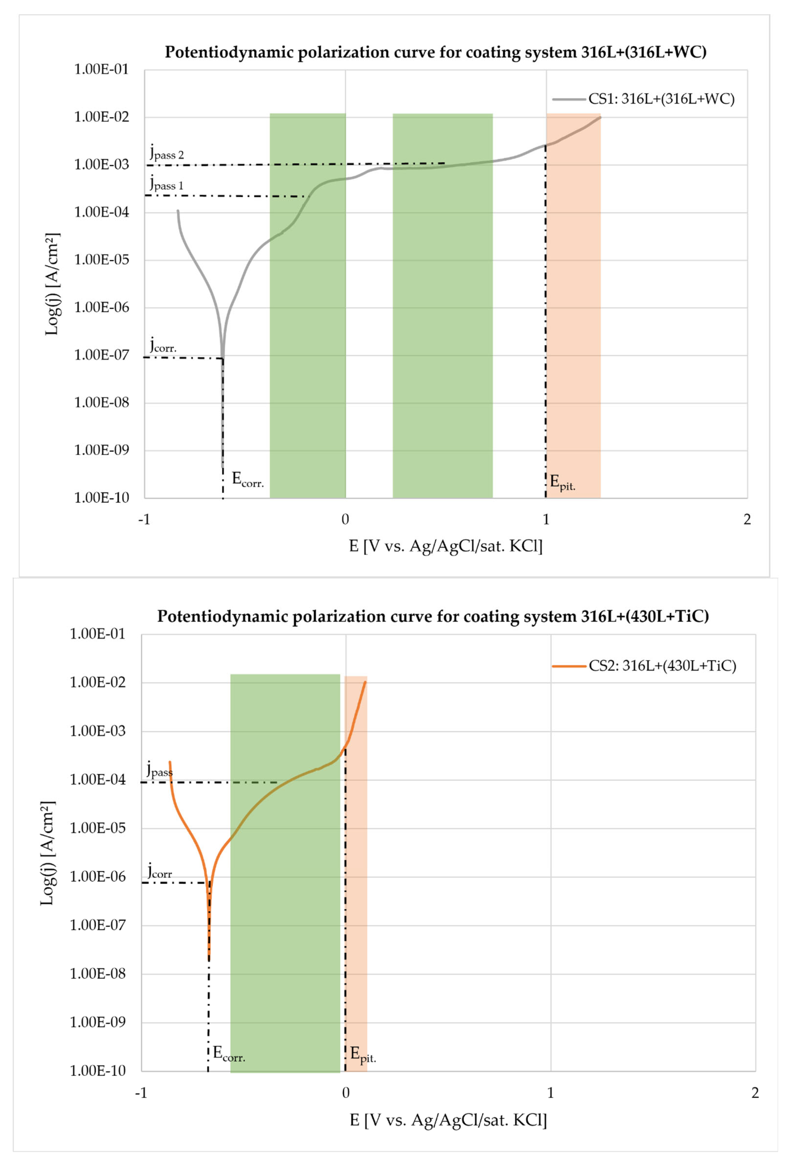
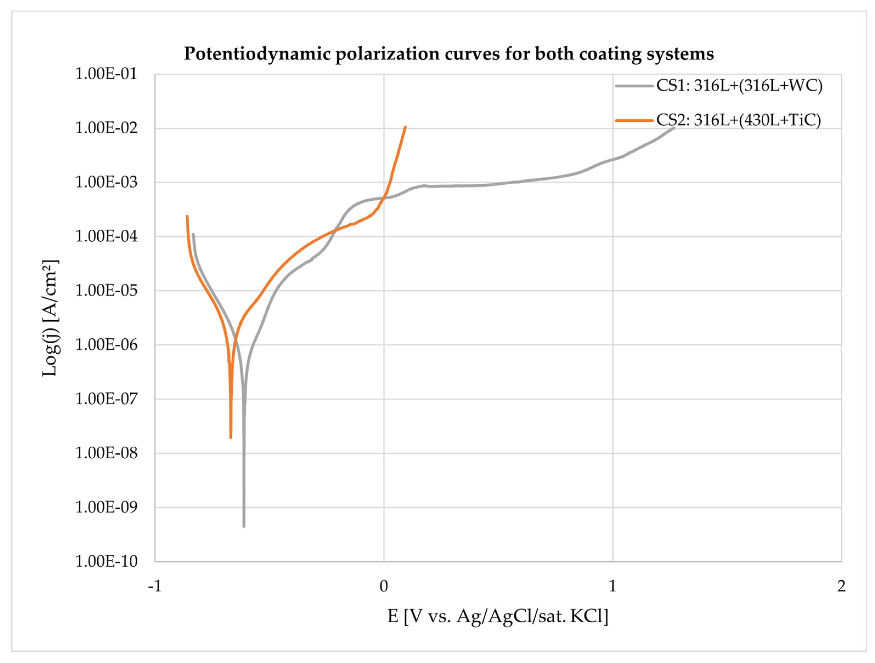
Figure 6.
Light microscopy (top row) and scanning electron microscopy (bottom row) images of the CS1 coating system (316L+(316L+WC)) before (left column) and after (right column) corrosion testing in 5 wt.% NaCl solution. Prior to corrosion, the spherical WC particles appear well-embedded within the austenitic 316L matrix, showing smooth interfaces and minimal surface irregularities. After exposure to the corrosive environment, the WC particles exhibit pronounced surface roughening and partial dissolution, indicating their susceptibility to chemical attack. The surrounding matrix also shows mild corrosion effects, particularly near particle-matrix interfaces, suggesting localized degradation due to microgalvanic interactions. *Note: The asterisk (*) next to the scale bar indicates that the scale was automatically generated by the ZEISS SEM system based on the magnification settings.
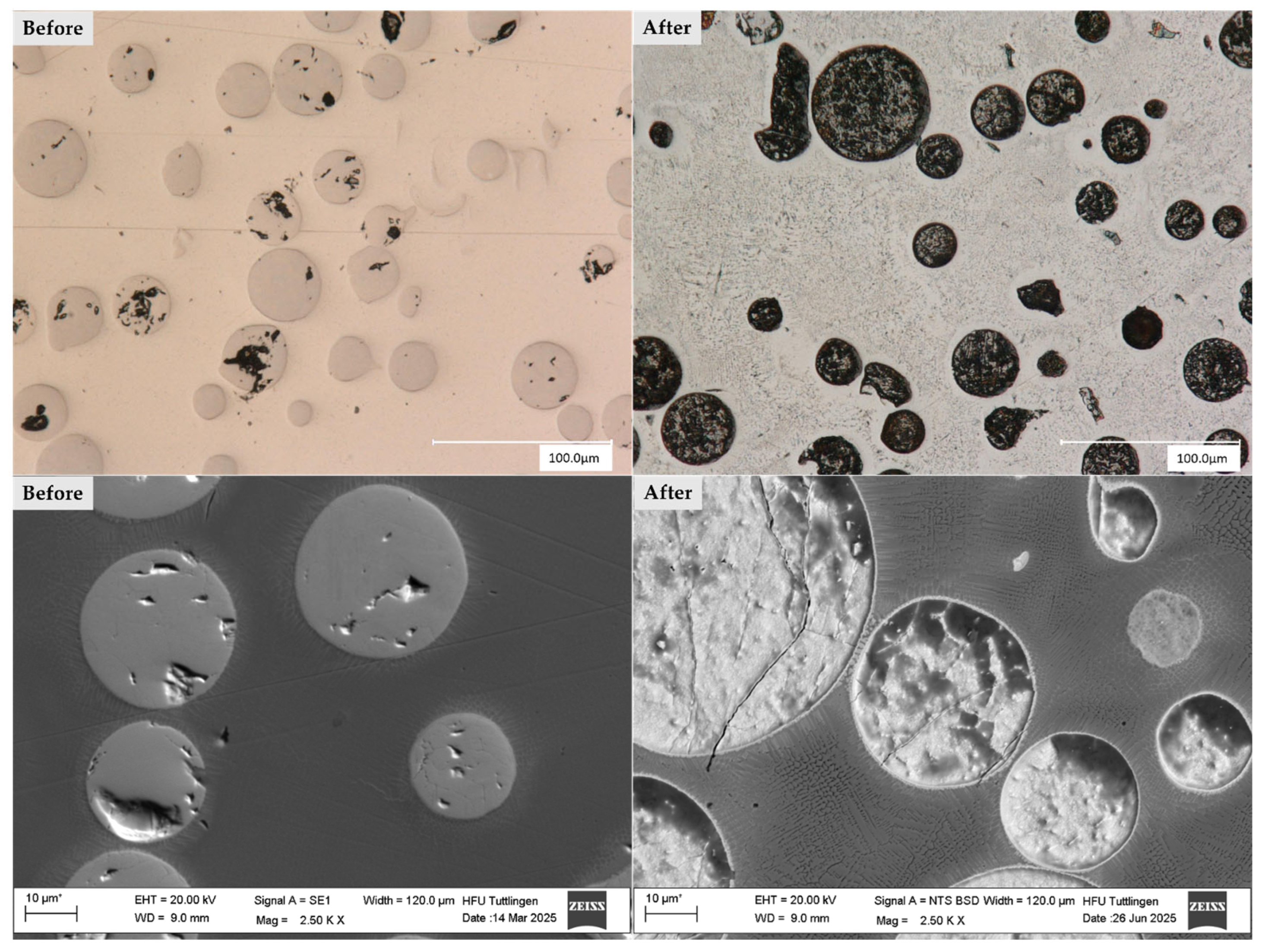
Figure 7.
SEM image and schematic illustration of a dissolution WC particle in the CS1 coating system (316L+(316L+WC)) after corrosion testing in 5 wt.% NaCl solution. The SEM image (left) shows interfacial white lines around WC particles, marked by yellow line arrows, indicating elemental diffusion during the laser deposition process. The corroded area of the surrounding matrix is highlighted with a yellow rectangle. The schematic (right) visualizes the diffusion of W and C from the WC particle into the 316L matrix, where they interact with Cr to form secondary carbides such as CrC. These interfacial regions, while mechanically reinforcing, may act as weak points for corrosion initiation due to their heterogeneous composition and disrupted passive film formation. *Note: The asterisk (*) next to the scale bar indicates that the scale was automatically generated by the ZEISS SEM system based on the magnification settings.
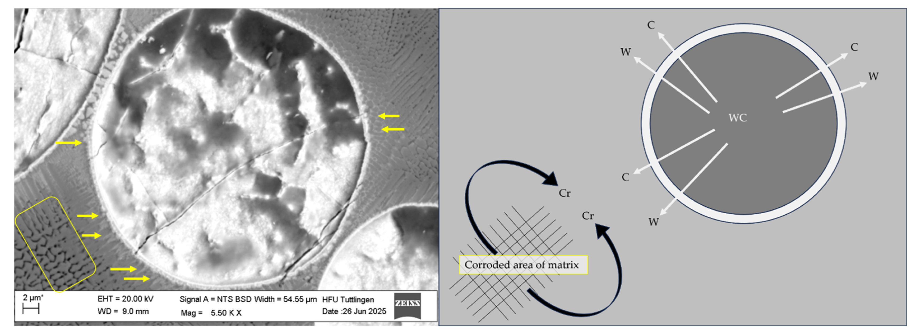
Figure 9.
SEM images showing surface morphology before (left) and after (right) corrosion testing at two magnification levels. Top row: scale bar 100 µm; bottom row: scale bar 10 µm. Post-corrosion imaging reveals significant surface degradation, with localized pitting-like features attributed to microgalvanic interactions between the ferritic 430L matrix and TiC particles. TiC remained chemically stable and contributed to passive film formation. *Note: The asterisk (*) next to the scale bar indicates that the scale was automatically generated by the ZEISS SEM system based on the magnification settings.
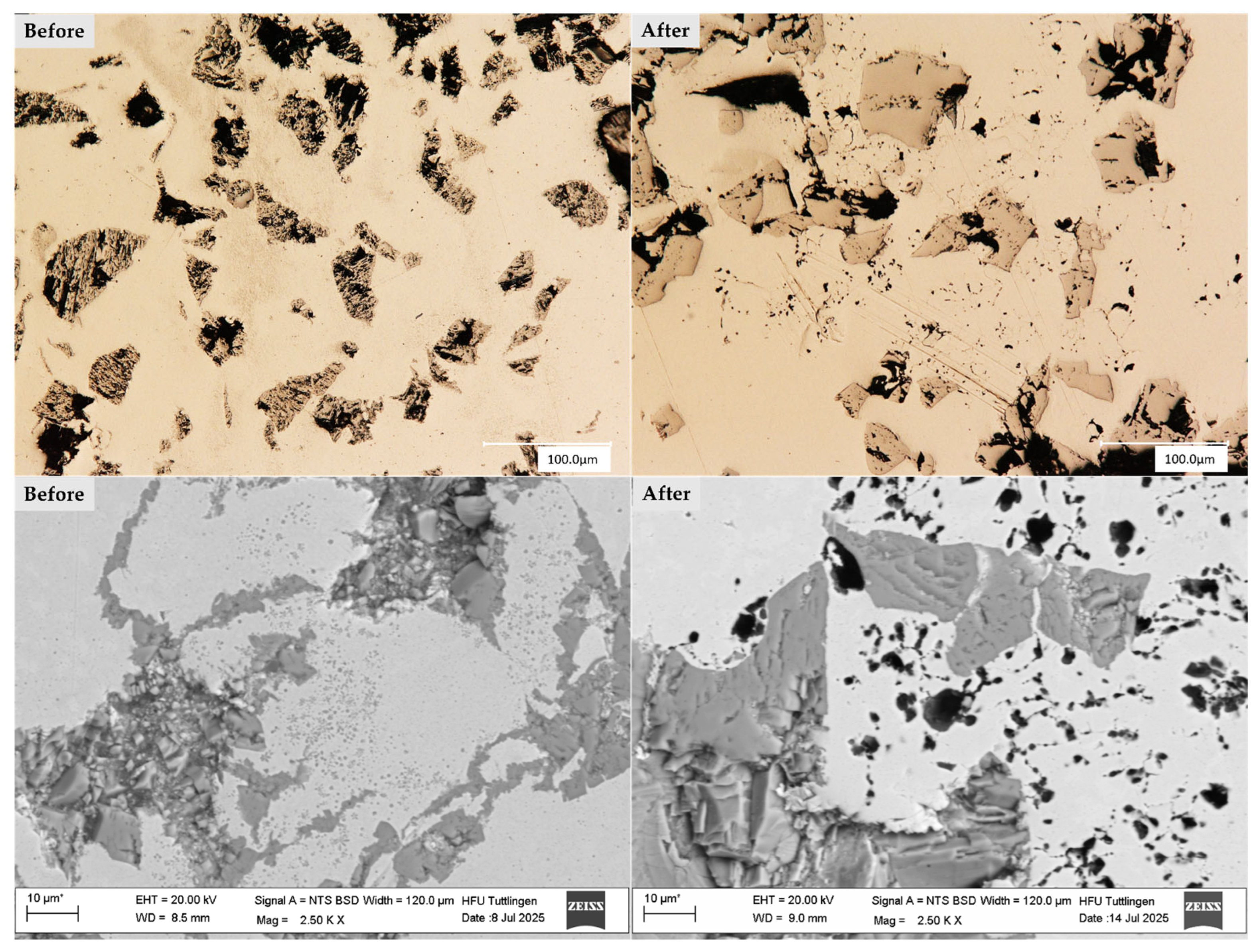
Figure 11.
SEM micrographs of the 316L+(430L+TiC) coating system before (left) and after (right) corrosion testing. Marked points (S1–S8) indicate EDS measurement locations.
Figure 11.
SEM micrographs of the 316L+(430L+TiC) coating system before (left) and after (right) corrosion testing. Marked points (S1–S8) indicate EDS measurement locations.
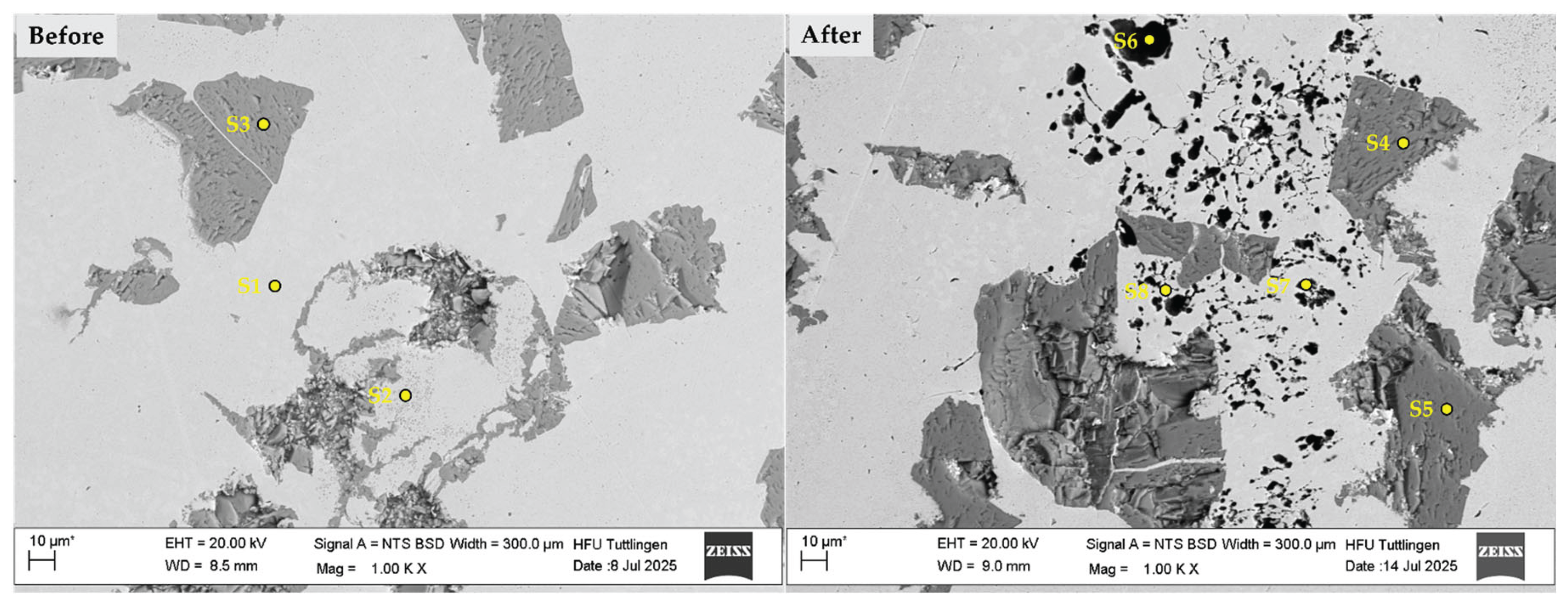
Table 1.
Chemical composition of the GJL substrate, the 316L and 430L powder.
| Element [wt. %] | GJL 150 | 316L | 430L |
| C | 3.50 ± 0.1 | Max. 0.03 | 0.03 |
| Si | 2.00 ± 0.1 | 0.80 | 0.9 |
| Mn | 0.60 ± 0.05 | 1.0 | 0.1 |
| P | < 0.10 ± 0.02 | - | 0.01 |
| S | < 0.08± 0.02 | < 0.01 | <0.01 |
| Cu | 0.20 ± 0.02 | 0.00 | 0.0 |
| Cr | 0.20 ± 0.02 | 17.00 | 17.00 |
| Mo | 0.35 ± 0.1 | 2.5 | - |
| Ni | < 0.20 | 12.00 | <0.60 |
| Sn | < 0.10 | - | - |
| N | - | - | - |
| Fe | Balance | Balance | Balance |
Table 2.
List of coating systems.
| Coating systems (CS) | Substrate | First layer | Second layer | Hard particles | Surface condition |
| 1 | GJL | 316L | 316L | Spherical WC | 1 µm polished |
| 2 | GJL | 316L | 430L | Angular TiC | 1 µm polished |
Table 3.
Electrochemical parameters derived from potentiodynamic polarization tests for the multilayer coating systems 316L+(316L+WC) (CS1) and 316L+(430L+TiC) (CS2) in 5 wt.% NaCl solution. The table includes corrosion potential (), corrosion current density () with standard deviation, anodic and cathodic Tafel slopes (, ), calculated corrosion rates, and chi-squared values indicating the quality of the Tafel fit. Corrosion rates are expressed in micrometers per year (µm/year), equivalent to millimeters per year (mmpy), with 1 mmpy = 1000 µm/year. The inclusion of standard deviation for enhances the statistical robustness of the comparison between coating systems.
| Coating system (CS) | Ecorr [mV] | Jcorr [A/cm²] | Standard deviation | Beta A [V/dec] | Beta C [V/dec] | Corrosion Rate [mmpy] | Chi Squared | Rp |
|---|---|---|---|---|---|---|---|---|
| 316L+(316L+WC) (1) | -611.0 | 7.39E-07 | 5.07E-07 | 1.30E-01 | 1.23E-01 | 0.86E-02 | 10.91 | 37.060 |
| 316L+(430L+TiC) (2) | -665.3 | 2.833E-06 | 1.19E-06 | 1.92E-01 | 1.39E-01 | 3.29E-02 | 9.46 | 12.357 |
Table 5.
Atomic concentrations [%] of selected elements at EDS measurement points before and after corrosion testing. Increased Na and Cl levels at S6, S7 and S8 indicate corrosion product accumulation. Reduced Cr content suggests localized chromium depletion. The absence of a significant change in TiC composition indicates chemical stability during corrosion. *Note: The asterisk (*) next to the scale bar indicates that the scale was automatically generated by the ZEISS SEM system based on the magnification settings.
Atomic concentration [%]
| Spectrum | C | Na | Si | Cl | Ti | Cr | Fe |
| S1 | 1.315 | 0.000 | 0.677 | 0.000 | 1.878 | 16.398 | 79.732 |
| S2 | 1.700 | 0.000 | 0.270 | 0.000 | 5.710 | 16.860 | 75.460 |
| S3 | 18.213 | 0.000 | 0.122 | 0.000 | 80.829 | 0.094 | 0.742 |
| S4 | 18.581 | 0.000 | 0.000 | 0.000 | 80.475 | 0.001 | 0.943 |
| S5 | 18.169 | 0.000 | 0.000 | 0.000 | 81.215 | 0.000 | 0.616 |
| S6 | 8.277 | 5.386 | 0.000 | 5.524 | 10.740 | 10.199 | 59.874 |
| S7 | 7.347 | 3.807 | 0.000 | 1.819 | 15.350 | 15.332 | 56.345 |
| S8 | 5.336 | 2.067 | 1.068 | 1.377 | 16.886 | 14.918 | 58.348 |
Disclaimer/Publisher’s Note: The statements, opinions and data contained in all publications are solely those of the individual author(s) and contributor(s) and not of MDPI and/or the editor(s). MDPI and/or the editor(s) disclaim responsibility for any injury to people or property resulting from any ideas, methods, instructions or products referred to in the content. |
© 2025 by the authors. Licensee MDPI, Basel, Switzerland. This article is an open access article distributed under the terms and conditions of the Creative Commons Attribution (CC BY) license (http://creativecommons.org/licenses/by/4.0/).
Copyright: This open access article is published under a Creative Commons CC BY 4.0 license, which permit the free download, distribution, and reuse, provided that the author and preprint are cited in any reuse.


