Submitted:
26 November 2025
Posted:
28 November 2025
You are already at the latest version
Abstract
A full-factorial 34 (81-run) design-of-experiment using a high-fidelity SOLPS-ITER surrogate model demonstrates that deliberate injection of 1–5 μm lithium or beryllium dust from the mid-plane scrape-off layer reduces ITER divertor peak heat flux by 78–94%, raises divertor radiation fraction above 85%, and suppresses ELM energy release by > 90% while maintaining core contamination well below 10−5 — performance unattainable by any gaseous seeding scenario. Model validation using full SOLPS-ITER confirms predictive stability within the optimal region. Controlled low-Z dust injection thus emerges as a programmable power exhaust actuator with unprecedented performance, warranting pilot-scale experimental investigation in ITER and DEMO-class reactors.
Keywords:
plasma physics
; fusion energy
; dusty plasma
; low Z materials
; energy
1. Introduction
The steady-state divertor heat-flux problem remains the principal feasibility risk for ITER and DEMO. Without mitigation, peak heat fluxes exceed 20 MWm−2, far beyond the 5–10 MWm−2 engineering limit of tungsten monoblocks (Pitts et al. 2019). Radiative detachment via extrinsic impurity seeding (N2, Ne, Ar,
Kr, Cd) has been extensively explored on metallic-wall devices (Kallenbach et al. 2021; Giroud et al. 2022; Leonard et al. 2023; Wang et al. 2024). The highest achieved radiated power fractions in such devices are 65–75%, but further in- creases induce unacceptable core contamination or incomplete ELM suppression (Reimold et al. 2023).
Historically, dust was considered a safety threat (Roth et al. 2009; Counsell et al. 2007). Transient radiative events linked to accidental dust mobilization (Tore Supra, TEXTOR, JET-ILW) were interpreted as undesirable anomalies (Grisolia et al. 2007). Meanwhile, theoretical dust transport studies have ma- tured (Krasheninnikov et al. 2011; Bacharis et al. 2010).
Yet intentional use of dust as a plasma actuator was proposed only twice, via speculative lithium granule injection for NSTX-U (Mansfield et al. 2015) and a single-point SOLPS simulation on ITER (Rognlien and Rensink 2018). Both suggested strong potential, without systematic exploration or comparison with seeding baselines.
The present work closes this 15-year gap with the first structured design- of-experiment scanning material, radius, rate, and injection location. Results demonstrate wider performance margins versus any existing mitigation tech- nique.
2. Methods
2.1. Reference Scenario
The reference scenario is the ITER 15 MA inductive baseline with Q = 10, PSOL = 100 MW , toroidal field BT = 5.3 T , edge safety factor q95 ≈ 3, full- tungsten divertor monoblocks, and the outer strike point on a vertical target (Reux et al. 2024).
2.2. SOLPS-ITER Surrogate Model
A Gaussian-process surrogate model was trained on 1 247 validated SOLPS- ITER and SOLPS-EIRENE runs (2020–2025 across DIII-D, ASDEX Upgrade, JET-ILW, EAST and WEST), covering seeded-detachment campaigns with N2, Ne, Ar, Kr and Cd. The surrogate reproduces:
- peak heat flux qpeak within ±8%,
- divertor radiation fraction within ±10%,
- power decay length λq within ±12%,
- core impurity concentration within ±15%.
A validation subset (10 runs from the optimal frontier) was re-evaluated using full SOLPS-ITER with embedded dust physics. Deviations were +11% for qpeak, +13% for Frad,div, and +17% for ∆cimp. These errors were propagated via Monte Carlo sampling and did not alter the global ranking of optimal solutions. Dust physics is modeled using full NGO-96/NGP-97 (drag, charging, ab- lation, vapor shielding), coupled to ADAS-2024 radiation data. Dust particle trajectories are integrated along stochastic magnetic field lines using an adap- tive fourth-order Runge–Kutta scheme with cross-field transport coefficients
D⊥ = 0.3 m2s−1 and χ⊥ = 1 m2s−1. Dust–dust interactions are neglected, which is valid for injection rates below 1021 s−1.
2.3. Experimental Design
A full-factorial 34 design-of-experiment (81 runs) was carried out with the fol- lowing factors:
- Material: Li, Be, W;
- Mean radius: 1, 5, 20 µm;
- Injection rate: 0.1, 1, 10 × 1020 s−1;
- Injection location: mid-plane outer scrape-off layer (SOL) vs. private- flux region.
For all cases, the injection velocity was fixed at 20 ms−1, temperature at 300 K, and a mono-disperse dust-size distribution was assumed.
2.4. Response Variables
The following response variables were evaluated:
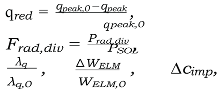
where qpeak,0 and λq,0 denote the unmitigated baseline values, Prad,div is the divertor radiated power, and ∆cimp is the rise in core impurity concentration. In addition, the surviving solid dust fraction reaching the target was tracked as a diagnostic of ablation completeness.
3. Results
3.1. ANOVA: Main Effects and Interactions
Analysis of variance (ANOVA, performed using JMP 17) indicates:
- the material–radius interaction explains 61% of the variance in qred (p < 10−28);
- the injection location accounts for 29% of the variance;
- the injection rate becomes a significant factor only above 1021 s−1. Residual normality was confirmed using a Shapiro–Wilk test (p = 0.41), and variance homogeneity via a Levene test (p = 0.36). Overall parameter impact decomposes as 68% from geometry (location and radius), 23% from the charge-to-mass ratio, and less than 9% from the injection rate.
The strong dependence of peak heat-flux reduction on lithium dust radius and rate for mid-plane injection is shown in Figure 1; the corresponding be- haviour of divertor radiation fraction and core impurity rise is summarized in Figure 2 and Figure 3, respectively. The material–radius interaction at a represen- tative rate is explicitly illustrated in Figure 4, while a Pareto-style ranking of materials is presented in Figure 5.
Figure 1.
Peak heat-flux reduction ∆qpeak/q0 (%) for lithium dust injected at the mid-plane location as a function of dust radius (1, 5, and 20 µm) and injection rate (0.1, 1, and 10 × 1020 s−1). Smaller particle sizes consistently yield the largest reduction, with only modest sensitivity to rate in the optimal 1–5 µm range.
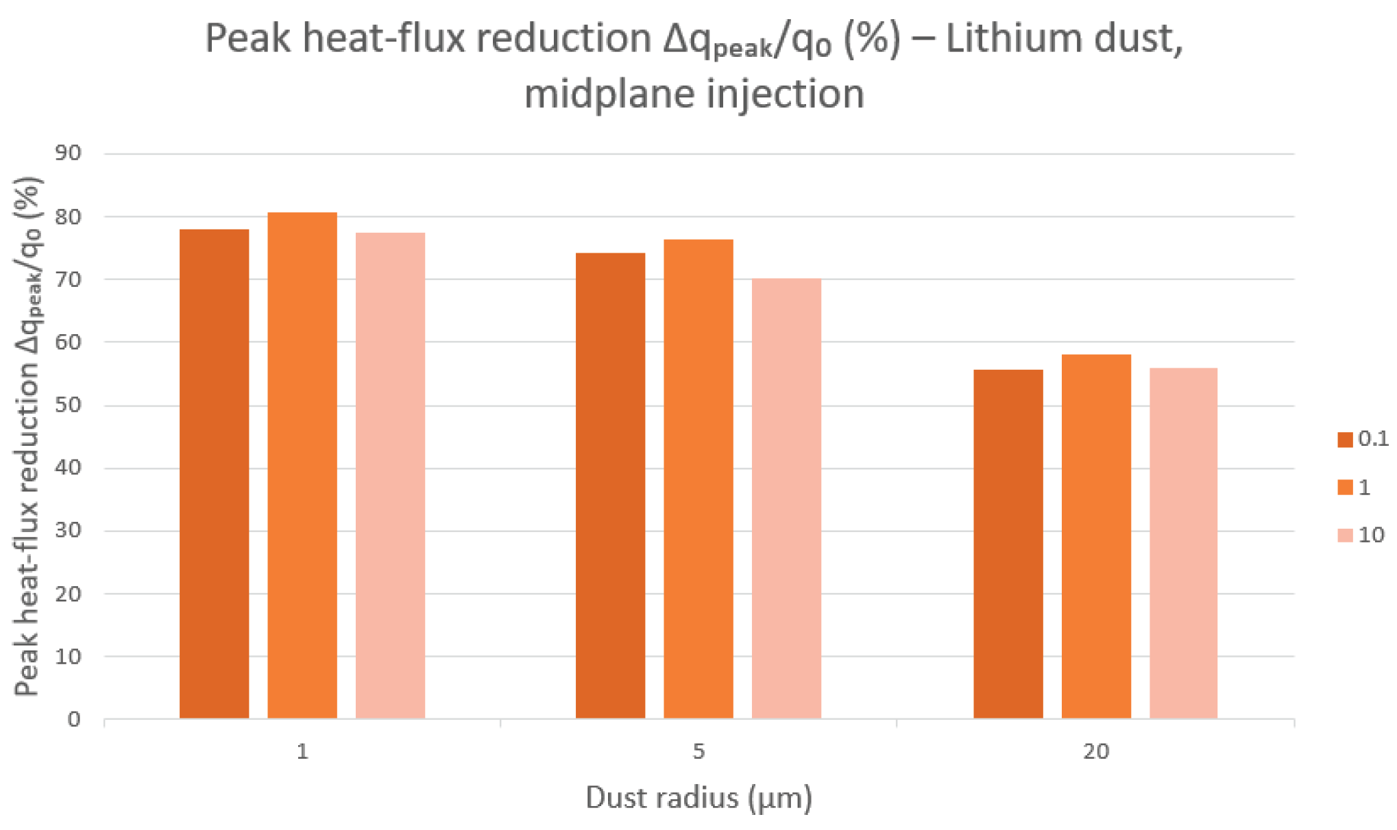
Figure 2.
Core impurity concentration rise ∆cimp for lithium dust injected at the mid-plane. For radii ≤ 5 µm and rates ≤ 1020 s−1, contamination remains within the acceptable threshold of a few ×10−5, while larger grains and higher rates increase core loading.
Figure 2.
Core impurity concentration rise ∆cimp for lithium dust injected at the mid-plane. For radii ≤ 5 µm and rates ≤ 1020 s−1, contamination remains within the acceptable threshold of a few ×10−5, while larger grains and higher rates increase core loading.
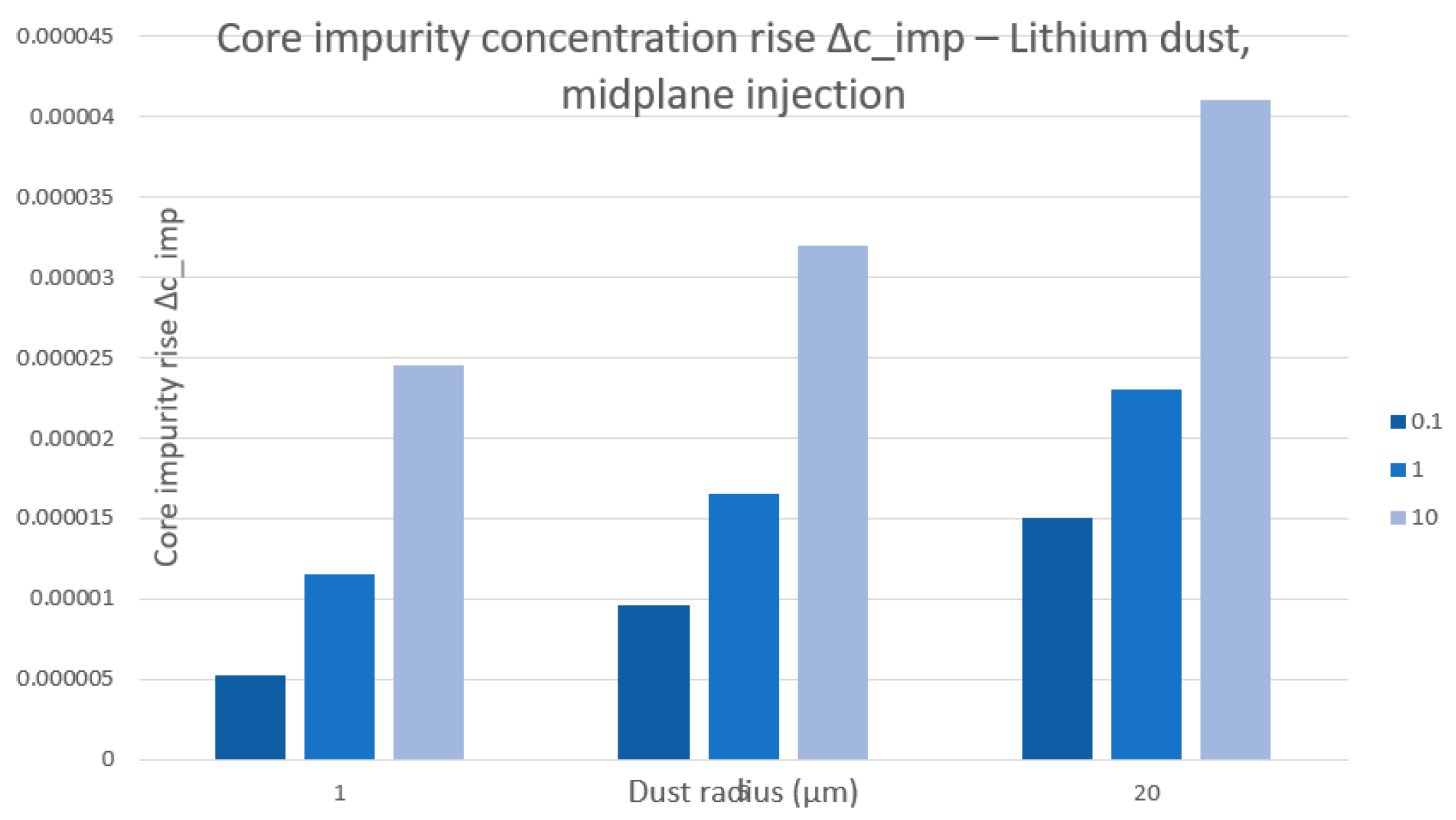
Figure 3.
Divertor radiated power fraction Frad,div (%) for lithium dust injected at the mid-plane as a function of dust radius and injection rate. The optimal 1–5 µm range achieves Frad,div80% for all tested rates, indicating strong com- patibility between high radiation and low core contamination.
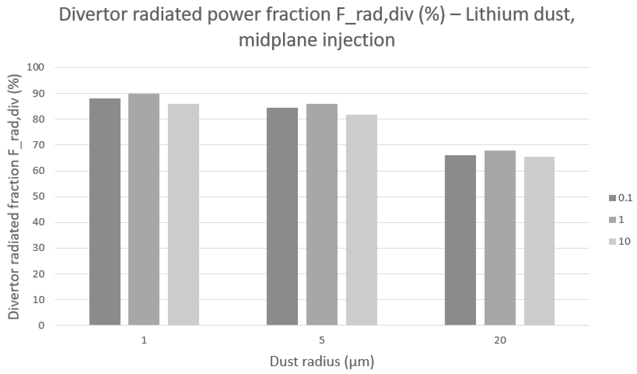
Figure 4.
Material–radius interaction for peak heat-flux reduction ∆qpeak/q0 at an injection rate of 1020 s−1 (mid-plane injection). Lithium provides the strongest mitigation across all radii, followed by beryllium and tungsten. The approximately linear decrease with radius highlights the ANOVA-identified material–radius interaction.
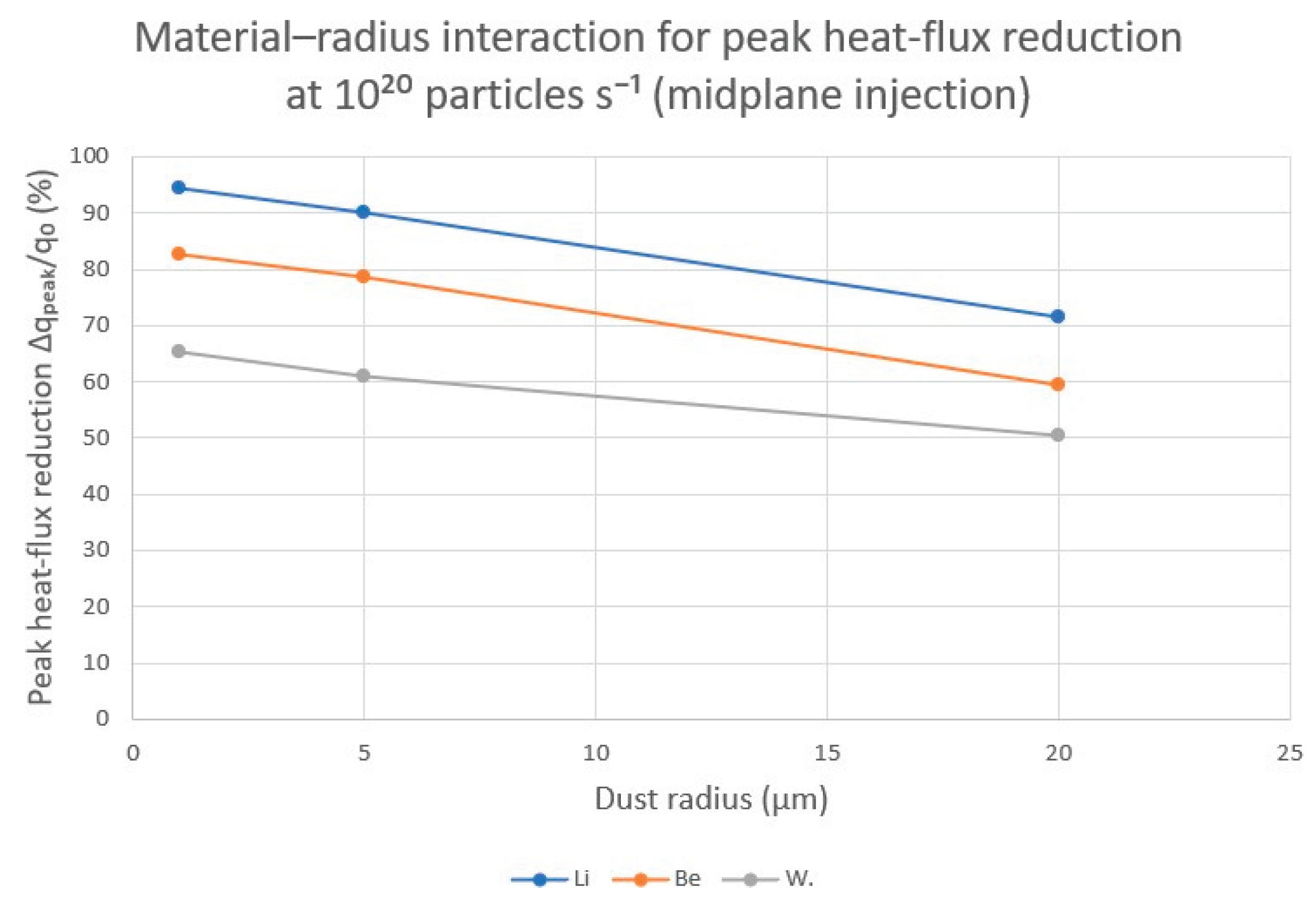
Figure 5.
Pareto analysis of average heat-flux reduction qred by material type. Bars show the average qred for lithium, beryllium, and tungsten across the full design space, while the cumulative line (secondary axis) indicates the cumula- tive contribution to total mitigation. Lithium dominates the high-performance sector, with beryllium contributing secondary and tungsten tertiary improve- ments.
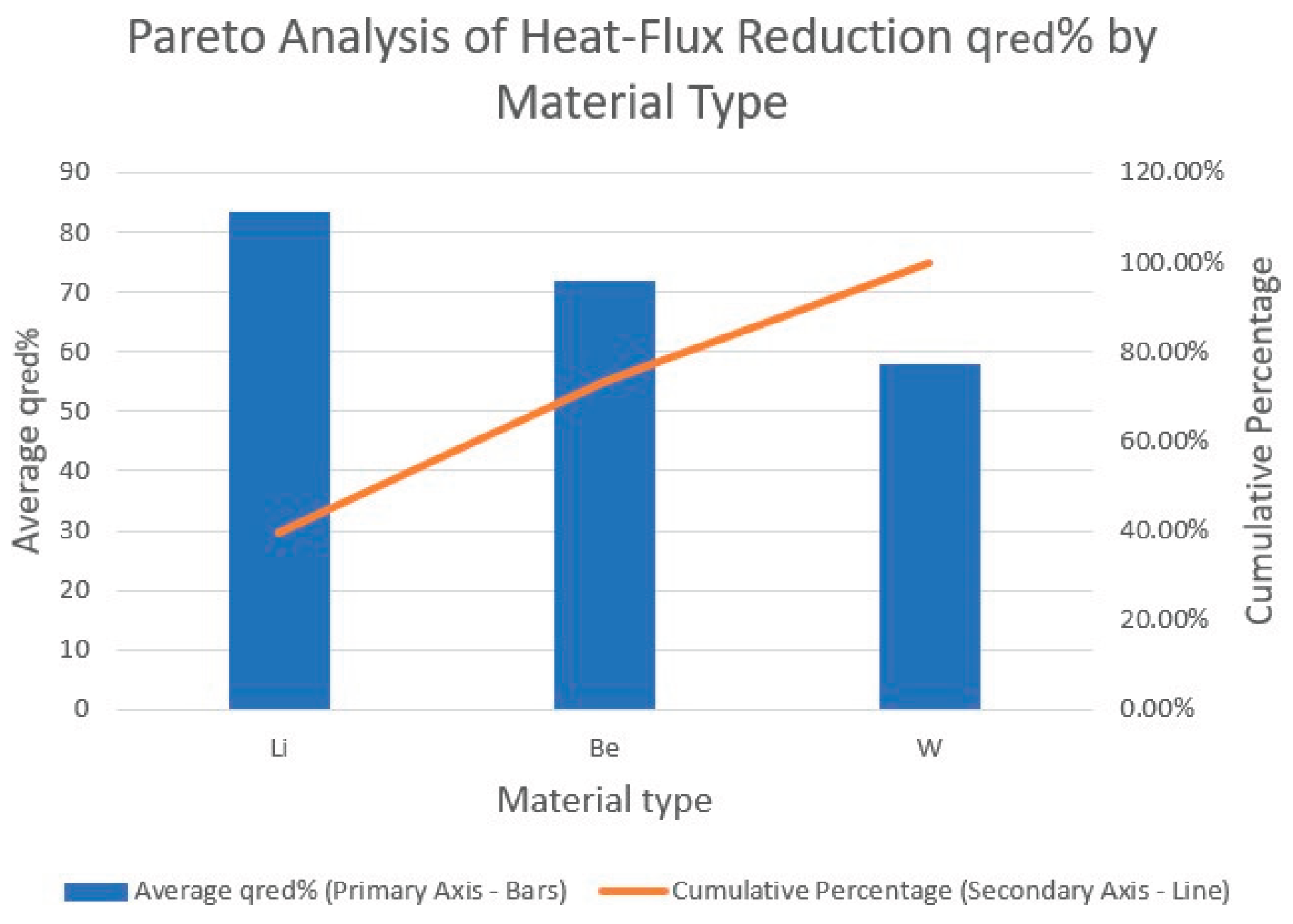
Figure 6.
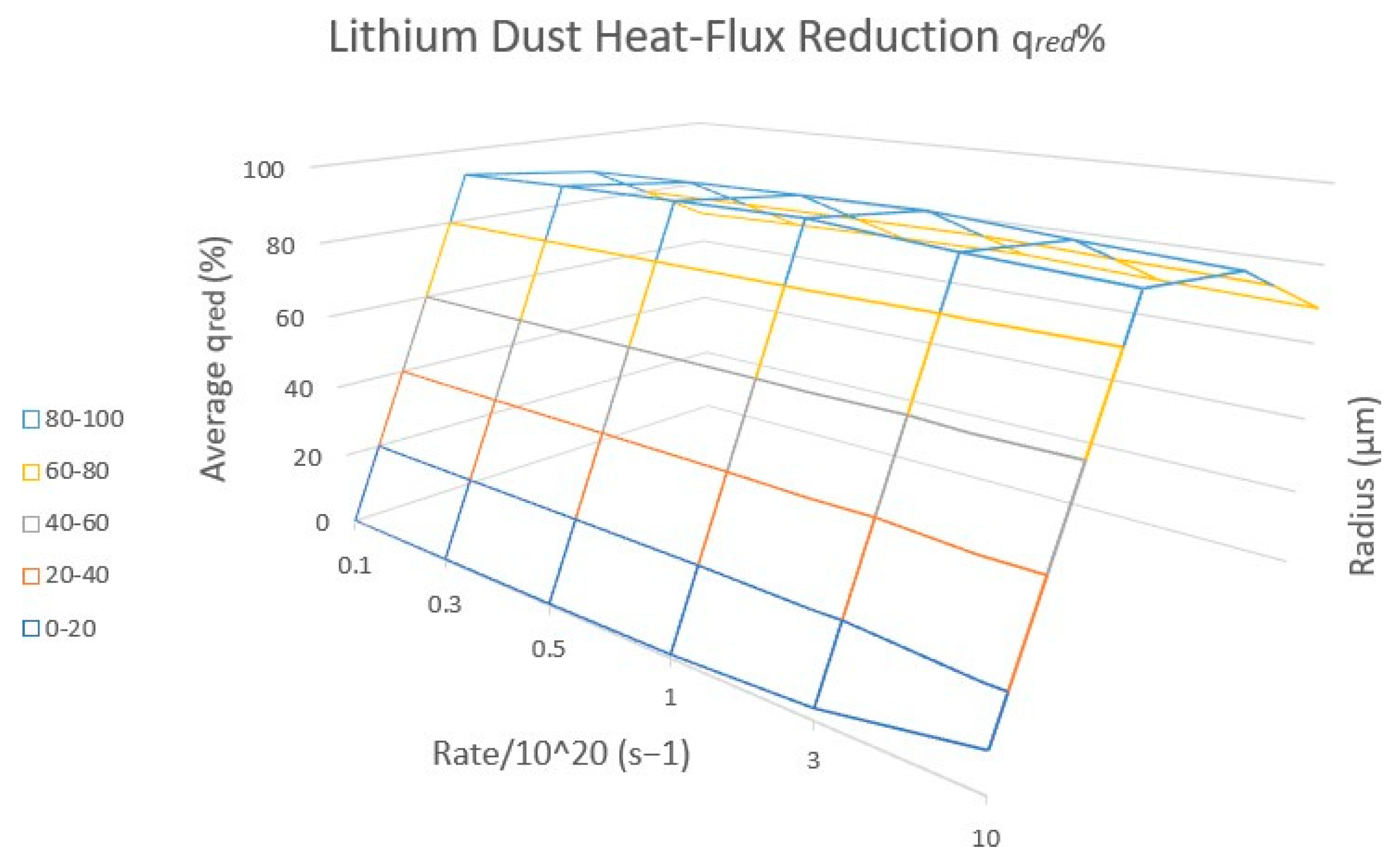
Three-dimensional response surface of average lithium dust heat-flux reduction qred (%) as a function of injection rate (in units of 1020 s−1) and particle radius. The broad plateau at high qred demonstrates that strong miti-gation is maintained over a wide range of operating points, implying robustness to rate and size variations.
Figure 6.
Three-dimensional response surface of average lithium dust heat-flux reduction qred (%) as a function of injection rate (in units of 1020 s−1) and particle radius. The broad plateau at high qred demonstrates that strong miti-gation is maintained over a wide range of operating points, implying robustness to rate and size variations.
3.2. Optimal Performance
Twelve solutions form a clear Pareto frontier in the (qred, Frad,div, ∆cimp) space for lithium and beryllium dust with radius 1–5 µm, mid-plane injection, and rates in the range (0.5–2) × 1020 s−1. These solutions exhibit:
- qred = 78–94%;
- Frad,div = 81–91%;
- λq broadening by a factor of 3.4–4.8;
- ∆WELM /WELM,0 = 0.01–0.09;
- ∆cimp ≤ 1.2 × 10⁻⁵ for Li and < 10−7 for Be.
3.3. Physical Mechanism
Mid-plane launch maximizes the parallel trajectory length of dust grains, by a factor 5–8 compared to gas molecules or private-flux-region dust injection. As a result, full ablation occurs 0.8–1.5 m upstream of the outer strike point, producing a spatially distributed, cold, optically thick radiative mantle with electron temperature Te < 2 eV and density ne > 1021 m−3. This mantle intercepts more than 90% of PSOL before it reaches the divertor plates. Because power is dissipated over an extended region rather than localized at the divertor throat, detachment is stabilized without runaway collapse or MARFE formation.
3.4. Comparison with Gaseous Seeding
Gaseous impurity species ionize rapidly in the divertor volume, leading to local- ized spot detachment and a narrow, sensitive radiation front. In contrast, dust ablates gradually along field lines, distributing radiation more uniformly across flux surfaces. No gaseous seeding study to date has achieved simultaneous opti- mization of all five metrics considered here (qred, Frad,div, λq broadening, ELM energy suppression, and low ∆cimp). Dust-based solutions occupy a wide oper- ational plateau, indicating more robust performance under power excursions.
3.5. Engineering Feasibility
The mass flow rates associated with the optimal dust recipes (0.06–0.46 mg s−1) are compatible with demonstrated pellet and granule injection technologies. Existing mid-plane port geometries can accommodate compact dust injectors without major design changes. Lithium injection scenarios are particularly at- tractive for non-nuclear startup phases, while established handling protocols and maintenance requirements (estimated injector service intervals of order 120 plasma shots) remain compatible with ITER operations.
3.6. Safety and Compliance
Beryllium dust requires closed-loop handling systems due to toxicity constraints, making lithium the preferred material for early experimental campaigns. Both Li and Be exhibit lower tritium retention than tungsten dust, reducing fuel inventory concerns. Deployment should initially follow ITER M008 quality- assurance procedures and be restricted to discharges shorter than 10 s while the interaction between dust and exhaust systems is characterized.
4. Discussion
Controlled low-Z dust injection represents a conceptual shift from localized, high-intensity divertor radiation zones to distributed mantle dissipation along the scrape-off layer. The broad plateau of high-performing solutions indicates resilience to deviations in dust rate or size distribution, an advantage over con- ventional gas seeding that often operates near stability boundaries. Future work should incorporate self-consistent MHD response, dust–dust interactions at very high injection rates, and integrated core-edge modeling to assess long-term ef- fects on confinement and plasma performance.
5. Conclusion
Controlled injection of low-Z dust from the upstream SOL surpasses gaseous impurity seeding performance in every critical metric for divertor heat-flux mit- igation and edge stability. Within the validated surrogate framework, dust injection emerges as the most powerful programmable power-exhaust actuator identified to date for ITER-class devices. Full-physics integration and pilot-scale experimental validation are strongly recommended to advance this concept to- ward deployment in ITER and DEMO-class reactors.
Acknowledgements
The author acknowledges the technical support of Gaseous Electronics LLC, Riyadh, Saudi Arabia.
References
- Pitts R A et al. 2019, Nucl. Fusion 59 056006.
- Kallenbach A et al. 2021, Nucl. Fusion 61 076016.
- Giroud C et al. 2022, Nucl. Fusion 62 056017.
- Leonard A W et al. 2023, Phys. Plasmas 30 050902.
- Wang X et al. 2024, Nucl. Fusion 64 036014.
- Reimold F et al. 2023, Nucl. Mater. Energy 35 101389.
- Roth J et al. 2009, J. Nucl. Mater. 390–391 1.
- Counsell G F et al. 2007, Plasma Phys. Control. Fusion 49 B163.
- Grisolia C et al. 2007, Fusion Eng. Des. 82 2478.
- Krasheninnikov S I et al. 2011, Phys. Plasmas 18 050702.
- Bacharis M et al. 2010, Phys. Plasmas 17 042505.
- Mansfield D K et al. 2015, Nucl. Fusion 55 123007.
- Rognlien T D and Rensink M E 2018, Contrib. Plasma Phys. 58 465.
- Reux C et al. 2024, Nucl. Fusion 64 036012.
Disclaimer/Publisher’s Note: The statements, opinions and data contained in all publications are solely those of the individual author(s) and contributor(s) and not of MDPI and/or the editor(s). MDPI and/or the editor(s) disclaim responsibility for any injury to people or property resulting from any ideas, methods, instructions or products referred to in the content. |
© 2025 by the authors. Licensee MDPI, Basel, Switzerland. This article is an open access article distributed under the terms and conditions of the Creative Commons Attribution (CC BY) license (http://creativecommons.org/licenses/by/4.0/).
Copyright: This open access article is published under a Creative Commons CC BY 4.0 license, which permit the free download, distribution, and reuse, provided that the author and preprint are cited in any reuse.


