

Submitted:
17 August 2025
Posted:
20 August 2025
You are already at the latest version
Abstract
This paper presents a preliminary safety assessment of the liquid deuterium premoderator container developed for the AlSUN ultra-cold neutron source, integrated into the thermal column of the WWR-K reactor. Analytical calculations, implemented using Python-based iterative schemes, were conducted to evaluate the container’s response under three categories of hypothetical accident scenarios: (1) power control and cooling failures, (2) breaches in the vacuum insulation, and (3) combustion-related incidents - liquid deuterium deflagration and detonation. Key thermodynamic parameters—including temperature and pressure evolution—were tracked in each scenario to characterize the transient system behavior. The resulting profiles were then used to estimate mechanical stresses on the container walls, considering the thermomechanical properties of the materials used in its construction. Special attention was given to the structural integrity of Aluminum Alloy 5056, assessing its performance under extreme thermal and mechanical loads. These findings lay a foundation for material selection and design optimizations, serving as a basis for future, more comprehensive studies employing advanced simulation tools.
Keywords:
ultra-cold neutrons
; cryogenic safety
; liquid deuterium
1. Introduction
Deuterium is widely used across various industries—from nuclear energy applications [1] to the chemical, biomedical [2], and medical sectors [3]. Due to its low neutron capture cross-section and high neutron moderation efficiency, it serves as an excellent moderator in nuclear research, particularly under cryogenic conditions. These properties make deuterium one of the key materials in the design of cold neutron (CN) and ultracold neutron (UCN) sources.
Currently, several research reactors operate with liquid deuterium (at approximately 20 K) placed near the reactor core for cold neutron production. Examples include two sources at the high-flux reactor of the Institut Laue–Langevin (ILL): one vertical (20 L) and one horizontal (6 L) [4], the FRM II source (30 L) [5], and the CN source at the OPAL reactor (20 L of deuterium) [6]. In addition, solid deuterium is used at the PULSTAR reactor to produce UCNs [7]. Since this work considers only reactor-based CN and UCN sources, accelerator-driven systems are excluded from the discussion.
It is worth noting that despite the widespread use of deuterium in various physical states, there have been no recorded major incidents—such as explosions, fires, or large-scale leaks—at any existing facilities that operate with liquid or solid deuterium near reactor cores.
Building upon international experience, the AlSUN (Almaty Source of Ultracold Neutrons) project aims to develop a new UCN and VCN sources at the WWR-K research reactor [8]. The design includes a liquid deuterium premoderator and a converter based on superfluid helium-4 (He-II) housed within the reactor’s thermal column, taking into account the unique technical, operational, and safety requirements associated with WWR-K installations.
Nevertheless, the use of deuterium—especially in liquid form—introduces several significant risks. Upon contact with air, deuterium can engage in highly exothermic reactions forming explosive mixtures, potentially leading to deflagration or even detonation. Such scenarios pose a threat not only to the UCN source equipment but also to overall reactor safety. Chemically and physically, liquid deuterium behaves similarly to liquid hydrogen, which is widely used in cold neutron sources.
Globally, dozens of reactor-based CN sources successfully operate using liquid hydrogen as a moderating medium [9]. The analysis of these foreign systems offers important insights for assessing safety in the AlSUN project. For example, reference [10] analyzes various accident scenarios for the cold neutron source using liquid hydrogen at the High Flux Isotope Reactor (HFIR, USA), including leak simulations, ignition modeling, thermal loads, structural strength evaluation, and the effectiveness of engineered safety measures. Report [11] provides a detailed assessment of similar risks at the National Institute of Standards and Technology (NIST, USA), including rupture and ignition scenarios. Furthermore, study [12], focused on the liquid hydrogen CN source at the JRR-3 reactor (Japan), describes a full-scale experiment involving a real-system detonation, which confirmed the structural resilience and absence of leaks or damage.
These studies demonstrate that, with proper engineering, systems using liquid hydrogen—and by extension, liquid deuterium—can be operated safely even under severe postulated scenarios. Accordingly, existing risk assessment methodologies and safety design principles from hydrogen-based systems can be adapted for the UCN source in the AlSUN project.
In hydrogen-handling systems, safety design typically focuses on industrial and technological installations where the greatest risks stem from leaks, accumulation of explosive mixtures, and storage of large hydrogen volumes. In reference [13], risk assessment methods are categorized into three main groups: use of tabulated safety distances, scenario-based analysis, and quantitative probabilistic risk assessment. The author emphasizes that while tabulated approaches are convenient for standard cases, scenario analysis allows for consideration of specific plant conditions, and probabilistic methods provide quantitative evaluation of rare but potentially critical events.
To minimize risks, the AlSUN project adopts a comprehensive, multi-level safety strategy aligned with the principles of “defense-in-depth” as outlined by the International Atomic Energy Agency (IAEA) [14,15,16], in combination with scenario-based reliability evaluation. The defense-in-depth concept involves multiple independent and sequential barriers to prevent accidents and to localize and mitigate their consequences should they occur.
Specifically, the AlSUN system is structured around three interdependent safety levels:
- Reactor interface safety, involving the protection of standard reactor operations, radiation shielding, and containment;
- Process and fire safety, addressing hazards associated with cryogenic liquids, pressurized gases (particularly D2 and He), and flammable environments;
- Personnel and environmental safety, ensured through radiation shielding, automated monitoring and emergency shutdown systems, ventilation, and safe disposal of activated materials.
This tiered protection strategy aligns with IAEA recommendations on the classification of components according to their safety significance and the integration of both engineering and administrative control measures to protect personnel, the public, and the environment.
At the current stage of the project, the primary focus lies on reactor interface and fire safety analysis. This effort supports the justification of the preliminary system design, including key engineering parameters such as component geometry, wall thicknesses, and element placement. These parameters influence not only structural reliability but also critical physical characteristics of the source—such as neutron transport, shielding efficiency, and radiation-induced thermal loads.
The structure of this article is as follows: Section 2 outlines the overall AlSUN source concept, with an emphasis on the liquid deuterium premoderator. Section 3 describes theoretical assumptions and postulated accident scenarios. Section 4 presents modeling results and their analysis, and discusses the findings and engineering implications. Section 5 concludes the study. Appendix A provides derivations of key theoretical expressions used in the stress calculations.
2. Concept of the AlSUN UCN Source at the WWR-K Reactor
The WWR-K reactor is a 6 MW light-water moderated facility with a structural layout nearly identical to the WWR-M reactor [17]. It features a 1-meter diameter thermal column adjacent to the core, where housing of the AlSUN UCN source is planned, with a 15 mm thick stainless steel reactor pressure vessel wall separating the source and the reactor’s active zone. Figure 1 shows the reactor geometry.
The proposed AlSUN source concept, illustrated in the Figure 2, includes a lead shield with heavy water cooling to suppress -radiation, a graphite moderator at 300K, a LD2 premoderator at 20K, and a SuperFluid 4He (SF 4He) converter at <1 K. Fast neutrons are thermalized in water and graphite, then slowed to cold energies in LD2, and finally downscattered in SF 4He.
UCNs generated in the SF 4He trap are extracted through a narrow aperture and transported by a dedicated neutron guide. Unlike TRIUMF [18] and PNPI [19], AlSUN separates the UCN and heat transport paths: the former via a compact guide, the latter through a thermally conductive wall. This enables higher UCN densities by limiting the active volume and suppressing losses in neutron guides.
The trap walls are coated with high Fermi potential materials to minimize UCN loss. A thin aluminum foil separates the trap and guide volumes, providing thermal and contamination isolation. The LD2 layer is thicker on the reactor side to enhance neutron moderation and shield the SF 4He from fast neutrons.
Unlike previous designs where SF 4He flows freely to an external refrigerator, AlSUN employs a local thermal path and aims to demonstrate that sufficient cooling can be achieved without compromising UCN density. Besides that, there will be innovative approaches related to neutron optics to increase efficiency of ultra-cold neutrons production. To validate this, experimental studies are planned on (1) heat extraction at cryogenic temperatures, (2) internal coatings for UCN storage, and (3) optimization of UCN transport optics.
The proposed design choices of the deuterium system in this work are mostly taken similar to the PNPI’s source. Preliminary neutronics (MCNP) and thermal physics (Comsol Multiphysics) assessments were conducted using a simplified model to establish key design parameters. This study focuses on defining critical structural aspects, including wall thicknesses, valve specifications, and stiffener requirements, to ensure the mechanical integrity and operational reliability of the system.
An alternative design for the deuterium system, currently under consideration by the AlSUN team, involves a circulating deuterium loop analogous to the configuration employed at the TRIUMF UCN source. In this approach, the helium coolant is eliminated, and the deuterium is connected directly to an external heat exchanger. At the present stage, both design concepts are being evaluated and compared with respect to their operational efficiency, safety implications, and economic feasibility.
2.1. Deuterium Section of the Cryogenic Module
As previously discussed, the presence of the liquid deuterium (LD2) premoderator introduces the most significant safety challenges in the AlSUN system. Therefore, ensuring its reliability, longevity, and compliance with radiation safety and nuclear regulatory standards is essential.
All components in the deuterium subsystem—including the premoderator chamber, helium cooling envelope, thermal shield, and feed/return lines for both deuterium and helium—will be fabricated from Aluminum Alloy 5056. This alloy is selected for its excellent mechanical performance at cryogenic temperatures, where it exhibits increasing ductility and energy absorption with decreasing temperature [22]. Under normal operating conditions, the thermal shield, the deuterium moderator chamber, and helium lines are maintained at approximately 20 K. Bellows-type expansion joints will be employed to accommodate thermal contraction and expansion in the low-temperature piping.
The deuterium loop will operate as a closed system comprising a safety reservoir, a network of valves, and the premoderator chamber housed within a helium envelope as can be seen in Figure 3. According to thermophysical studies [23], at a nominal pressure of 1.5 atm, boils at 24.117 K. To prevent local solidification and associated risks of blockage or overpressure, the operating temperature must be maintained strictly between the triple point of deuterium (18.73 K) and its boiling point. The helium refrigerator flow provides the cooling necessary to condense and to dissipate radiation-induced heating. In addition to servicing the deuterium circuit, the refrigerator ensures the thermal shielding of the entire low-temperature assembly. The helium envelope serves dual purposes: enabling efficient deuterium condensation and, together with the surrounding vacuum vessel, acting as an additional barrier that prevents direct contact between deuterium and atmospheric air, thereby enhancing overall operational safety.
The chamber layout is illustrated in Figure 3, showing an inner LD2 (green) shell enclosed by a cooling helium envelope (dark blue). The placement of the deuterium inlet at the top of the chamber is designed to promote stable vapor release during system warm-up. As shown earlier in Figure 2, the entire deuterium module is positioned within a vacuum vessel, beyond which graphite reflectors are maintained at approximately 300 K. Although graphite is present structurally, it was excluded from the mechanical stress analysis to maintain a conservative approach, ensuring that stress predictions represent a worst-case scenario.
In future design iterations, additional structural elements such as stiffening ribs (illustrated in Figure 3), isolation valves, and cold receivers will be incorporated into detailed modeling and optimization. While these components are not yet included in the current structural calculations, their presence will contribute to the reinforcement of the chamber and may reduce localized stress concentrations. Their omission in this phase aligns with the preliminary nature of the current safety evaluation and will be revisited in subsequent refinement stages.
3. Materials and Methods
In this work, we performed an analysis of credible abnormal situations and highly unlikely accidents, ensuring that the UCN source’s deuterium chamber performs safely even with conservative approaches. We conducted analytical calculations using Python-based iterative schemes to gain initial insights into the container’s behavior under various accidental conditions. These conservative calculations, grounded in fundamental engineering principles and existing material property data, addressed factors such as pressure build-up, thermal loads, and associated stresses. Although these analyses do not incorporate complex validated simulation tools or the latest nuclear data sets at this stage, they lay the groundwork for more comprehensive studies. Subsequent investigations will leverage advanced computational modeling, enhanced nuclear data inputs, and robust validation efforts to further refine and optimize the container design, ultimately contributing to safer and more efficient UCN source operations. The properties of deuterium employed in our calculations are present in the Table 1. Notably, the high value of the specific heat of deuterium together with its high mass provides us with relatively high time of response to accidental scenarios. In cases without available deuterium chemical properties’ data, hydrogen properties were adopted.
In this work we consider all the possible scenarios, including system’s cooling failure, loss of isolation vacuum, which with potential fracture of deuterium chamber is leading to the maximum hypothetical accident - mixture of air and deuterium causing deflagration or detonation. In all the scenarios, first we track the temperature evolution of the deuterium, which we find from the enthalpy balance. These scenarios will be discussed in following paragraphs, highlighting the temperature and pressure evolutions, and resulting mechanical stresses experienced by the structure of the UCN source.
Strong assumption of zero temperature gradients within the deuterium moderator and container walls was adopted, hence, all reported results represent average values. Also, we assume the container is sealed and rigid, so the volume V is constant. Because the system can reach relatively high densities at cryogenic temperatures, applying the ideal gas law () may lead to non-negligible inaccuracies. In particular, strong intermolecular forces and significant molecular volumes invalidate the assumptions of an ideal gas under these conditions [25]. Therefore, to account for the real-gas behaviors, we use the Redlich–Kwong equation of state (EoS), which introduces empirical corrections for molecular volume and intermolecular attractions:
where a and b account for intermolecular forces and nonzero molecular volumes [27]. Compared with widely known Van der Waals EoS, Redlich–Kwong typically improves accuracy at elevated temperatures, while retaining simplicity for computational purposes. Redlich-Kwong EoS requires iterative or numerical methods to solve for P at the final temperature and known moles n (or molar volume ), especially since these expressions are nonlinear. We implemented these calculations in Python, using standard root-finding routines.
With the internal pressure determined, the principal mechanical stresses in the container walls are evaluated using the thin-walled approximation - Mariotte model. The deuterium premoderator chamber consists of:
- Cylindrical walls (Deuterium–Vacuum and Deuterium–Helium interfaces),
- Spherical forward cap (Deuterium–Vacuum interface),
- Annular plate (Deuterium–Helium coolant interface).
The theory behind how stresses are computed for each geometry using appropriate forms of the Mariotte equations is presented in Appendix A. Failure is assumed to occur if exceeds the allowable stress , where is the 0.2 % yield stress of Aluminum Alloy 5056 and is the safety factor. Due to all the aforementioned assumptions, a conservative safety factor of is adopted (ASME BPVC Section VIII, Div. 1 (UG-23, UG-25)), which also accounts for uncertainty in material properties at cryogenic and elevated temperatures (20–600 K), and lack of fatigue or stress concentration analysis in this preliminary phase. The goal is to design the container that will plastically deform, but not catastrophically fail under extreme impulsive loading.
Finally, although this analysis focuses on the deuterium chamber, the helium coolant envelope acts as a secondary containment structure. Its walls serve as an additional safety barrier, enhancing the mechanical resilience of the overall cryogenic module in the event of partial failure.
3.1. Power Control and Cooling Failure
The uncontrolled power increase of the WWR-K reactor for more than 20 % (7.2 MWth) is leading to automatic control rods insertion, shutting down the reactor, according to WWR-K reactor’s safety guides. If the helium refrigerator fails, the helium coolant will no longer be available to recondense deuterium vapor, leading to a gradual rise in pressure within the moderator tank.
In cryogenic systems, three primary heat transfer mechanisms are typically considered: (1) thermal radiation from surrounding structures, (2) thermal conduction along mechanical supports and piping (“highways” and suspensions), and (3) energy deposition from neutron and gamma radiation originating from the reactor core. In the present analysis, conductive heat transfer via supports and piping is neglected, as it would require a comprehensive thermal model of the entire facility and is expected to contribute significantly less than the other two mechanisms. The radiative heat load was explicitly calculated and amounts to 24 W for the current configuration.
The contribution from reactor-induced radiation was estimated for the highest possible power using the Monte Carlo code MCNP 6.2 [29]. For the baseline configuration, where both the deuterium and helium moderator shells are made from Aluminum Alloy 5056, the following energy deposition rates were obtained:
- 69.1 W deposited in the deuterium moderator,
- 78.4 W deposited in the surrounding aluminum structure.
Eventually, the total heat load sums up to 171.5 W, which needs to be removed by a cooling system.
An alternative design was also evaluated, in which the walls of the helium moderator were assumed to be constructed from Zircaloy-4, while the deuterium moderator retained aluminum alloy walls. This change resulted in a reduction in heat generation within both the deuterium and helium volumes. However, the heat deposition in the Zircaloy-4 walls increased compared to aluminum, partially offsetting the gains in thermal performance. For this reason, the evaluation of the Zircaloy-based configuration has been deferred to future studies.
In the present work, deuterium is initially stored as a liquid at about 20 K, which is well below its normal boiling point. The overall heat rate that warms the liquid deuterium is specified as an external input. We adopt a piecewise approach to account for phase change and subsequent vapor heating:
- Liquid Heating (): From the initial temperature ( K) up to the boiling point ( K), the liquid deuterium is heated according towhere is the liquid heat capacity (assumed constant or defined by auxiliary data).
-
Vaporization (Isothermal at ): Once is reached, the phase transition from liquid to vapor occurs isothermally, requiring the latent heat of vaporization :During this step, the temperature nominally remains at until all liquid is evaporated.
- Vapor Heating (): If the energy supply continues after complete vaporization, the now gaseous deuterium is heated above . In our code, this can be treated via a constant vapor heat capacity or by a more detailed temperature-dependent correlation (e.g., using Shomate polynomials). The required energy is
The total heat needed to bring the entire mass from K to some final temperature is thus obtained by summing these contributions:
where each term is activated only when its respective temperature or phase-change regime is reached. In our simulations, a user-defined heat rate is specified, and we integrate or step through time to determine how accumulates and in which phase the deuterium resides at each stage. This analysis assumes a worst-case scenario in which pressure cannot be released due to simultaneous failure of both the pressure relief valve and deuterium return channel.
3.2. Loss of Isolation Vacuum
Loss of the isolation vacuum is among the most critical hazards in cryogenic systems, as any influx of ambient gas substantially increases heat transfer to cold surfaces. The severity of such an event depends on the rate of temperature rise within the cryogenic container: faster warming accelerates pressure buildup and raises the risk of mechanical failure. Initially the vacuum vessel has a pressure equal to Pa, reaching the atmospheric pressure at the end of the accident.
Two principal routes can lead to a total loss of insulating vacuum: (i) failure of the vacuum pump or the protective circuitry, allowing air to enter the vacuum container, or (ii) rupture of the premoderator chamber filling the vacuum vessel with deuterium. In the latter case, leaking D2 would expand into a larger vessel volume, quickly reducing the likelihood of overpressurization. Moreover, the absence of oxygen in the vacuum eliminates deflagration risks. Notably, reaching the vacuum space requires a simultaneous breach of both the deuterium chamber and its thin helium coolant envelope—multiple failures that further decrease the probability of such an incident. Even if a small leak occurs, the large vacuum volume and higher wall thickness lead to lower pressures and lesser stresses than in other scenarios.
Because the more consequential hazard is air ingress, this study focuses on the potential for ambient air to leak into the vacuum vessel. We analyze both the cylindrical sections and spherical cap of the moderator assembly, where radiation, conduction, and natural convection act with geometry-specific parameters. The annular plate surface is omitted from these calculations because it only faces helium coolant channels at low temperature, which would further reduce the deuterium temperature and thus yield a conservative overestimate of heat transfer when excluded, however stress calculations that the annular plate experiences are included in this work.
3.2.1. Cylindrical Geometry
We assume the deuterium container is coaxial with the vacuum vessel, forming a cylindrical gap whose pressure P increases over time from to . At each time step, the net heat flux into the container wall, , is computed as follows:
- Radiative Heat Transfer between concentric cylinders of emissivities and :where is the Stefan–Boltzmann constant, F is a view factor close to unity for nested surfaces, and is the inner cylinder’s external area.
- Conductive Heat Transfer through gas:where L is the cylinder’s axial length, and are the vacuum vessel’s inner radius and the container’s outer radius, respectively, and depends on the instantaneous pressure in the gap.
-
Convective Heat Transfer, which becomes significant as the gap pressure rises: The convective heat transfer rate between the cylindrical surfaces is determined using the Rayleigh number () and Nusselt number (). The Rayleigh number is calculated as:where g is the gravitational acceleration, is the thermal expansion coefficient, and are the temperatures of the interacting surfaces, L is the characteristic length, is the kinematic viscosity, and is the thermal diffusivity. For natural convection, the Nusselt number is estimated based on the Rayleigh number:The convective heat transfer coefficient is then given by:The convective heat transfer rate is finally computed as:where is the interacting surface area.
3.2.2. Spherical Cap Geometry
At the vessel’s forward region, the deuterium container features a spherical cap rather than a cylindrical surface. The gap between this cap and a larger enclosing dome is relatively small (on the order of 15 mm), so a parallel-plate approximation is employed to characterize radiative, conductive, and convective fluxes. Denoting the cap’s temperature by and the surrounding structure’s temperature by , we have:
Here, is the emissivity, is the Stefan–Boltzmann constant, is the spherical cap’s external surface area, is the effective thermal conductivity of the gas, and is the small radial distance of the gap. As in the cylindrical case, the total heat flux into the spherical cap is:
3.2.3. Container–Deuterium Coupling
By summing the heat flux contributions from the cylindrical and spherical sections, the overall thermal load on the premoderator container is determined. Helium cooling of deuterium and deuterium container’s wall was neglected to make the calculations more conservative, hence radiation heat rate coming from the WWR-K reactor was added (). The integrated model then updates the deuterium temperature and phase fraction over each time step, allowing an estimation of how quickly the system warms and how rapidly internal pressures rise.
At each time step the container wall temperature is first advanced with the net heat:
with and as the wall’s mass and specific heat, respectively. A separate conduction path through the wall thickness governs heat flow into the deuterium. Depending on phase-change behavior and fluid properties, and the vapor fraction are updated each step. The updated wall then conducts heat through the metal-helium–metal stack into the deuterium volume. We treat that conductive flux as:
where is the total wetted area (cylindrical + spherical cap) and are the individual layer thicknesses. The energy that actually reaches the deuterium over a time step is:
where stands for any direct radiation from the reactor that heats the deuterium.
Because the sign of in Eq. (17) can reverse, energy can flow from deuterium back to the wall whenever , ensuring the two bodies equilibrate instead of diverging. This explicit energy-balance update is repeated for every until the prescribed simulation time is reached. These transient temperature and pressure profiles are subsequently used with the mechanical stress calculations (see Appendix A) to verify if the Aluminum 5056 chamber remains within safe operational limits.
Ultimately, this unified approach provides a conservative estimate of heat ingress during a vacuum-loss event, whether in a cylindrical segment or at the spherical cap. It thus captures the critical pathways for radiative, conductive, and convective heat transfer under realistic leak conditions, enabling a thorough assessment of the deuterium system’s thermal and structural margins.
3.3. Liquid Deuterium Deflagration/Detonation Scenario
It is essential to evaluate whether a detonation—characterized by supersonic flame propagation and destructive blast waves—could feasibly occur in the proposed system. For cryogenic flammable gas mixtures such as deuterium–air, detonation requires conditions that are rarely achievable in practice.
The initiation energy required for detonation is orders of magnitude higher than for deflagration. Moreover, geometric constraints play a key role: for a self-sustaining detonation wave to form and propagate, the smallest dimension of the vessel or piping must exceed a critical threshold, typically greater than 12 times the detonation cell size . Experimental data [26] indicate that for stoichiometric deuterium–air mixtures, is small compared to other fuels but still requires channel diameters larger than those present in our system. For the most conservative stoichiometric case, the detonation critical tube diameter equals to 30 cm. In the AlSUN configuration, both the deuterium chamber and associated cryogenic piping are designed to be narrower than this critical limit, and no flame-accelerating obstructions (e.g., baffles or sudden contractions) are present.
Even the possibility of a deflagration-to-detonation transition (DDT) is highly unlikely. While DDT has been observed in large unconfined clouds under specific conditions—such as in petrochemical accidents involving multi-ton vapor clouds—these conditions include high turbulence, delayed ignition, and favorable geometry. None of these are present in the AlSUN moderator system. Additionally, any air that could leak into the cryogenic system would immediately freeze on contact with cold surfaces, preventing homogeneous mixing and flame propagation. Consequently, the possibility of detonation is dismissed on both physical and geometrical grounds, however it was assessed in this work for the completeness of analysis.
3.3.1. Deuterium Deflagration Analysis
First, we start with a more plausible deflagration scenario, where combustion occurs subsonically in a partially confined space. The primary hazard associated with deflagration is the rapid pressure rise resulting from exothermic chemical reactions in a closed or semi-closed system. This scenario considers how a known mass of cold liquid deuterium (), initially at approximately 20 K, may undergo deflagration upon contact with ambient air. Under normal operation, both deuterium and air components remain frozen, and gas-phase combustion is only possible during cryostat warm-up. To define bounding conditions for safety assessment, the container is modeled as adiabatic and isochoric, assuming thermally insulating walls and neglecting mechanical deformation over the timescale of the event. Adiabatic Isochoric Complete Combustion (AICC) pressures, , are therefore adopted as conservative estimates for the maximum overpressure that could arise.
The deflagration accident could originate from one of two principal initiating events. The first is a simultaneous rupture of the vacuum vessel and deuterium chamber shell, which would allow significant air ingress into the moderator volume. Although unlikely—given the robust shielding of the reactor thermal column and structural isolation of these components—this worst-case condition must be evaluated to set conservative design limits. The second, more credible pathway is a rupture of the deuterium feed or return lines while the fill-valve is open. In such a case, the ingress of air is limited to the volume of the piping network, and it is negligible compared to the 239.7 kg required for a stoichiometric mixture, which has volume concentrations of fuel and air such that no excess fuel or oxygen remains at the completion of the chemical reaction.
In the considered design, the deuterium container holds a prescribed quantity of (14 kg), while during a hypothetical accidental scenario air enters at a specified mass and temperature, simplified to 23.2% of and 76.8% of by mass, ignoring minor species like Ar, , etc. The combustion of deuterium is represented by a single-step reaction:
where partial or complete consumption of deuterium depends on whether the oxygen is below stoichiometric (), exactly stoichiometric (), or in excess (). Unreacted deuterium or oxygen, therefore, remains if one reactant is limiting, and the nitrogen remains inert.
Because the container volume is fixed, and no heat is assumed to leave or enter, the system evolves under adiabatic, constant-volume conditions. The final temperature is found by balancing enthalpies under the assumption that the gaseous species (, , , and ) behave ideally above 298 K. Liquid deuterium below its boiling point near 24 K is heated using piecewise constants for heat capacity and an appropriate latent heat term at vaporization. All chemical dissociation at high temperature and wall heat losses are neglected, producing a conservative upper-bound temperature estimate.
To formalize this, we write a typical adiabatic energy balance:
where and are the moles and enthalpies of each species i, respectively, and is the net enthalpy of reaction for the fraction of deuterium that reacts. Below 298 K, we account for liquid-vapor transitions of deuterium and any sensible heating to 298 K; above 298 K, we use Shomate polynomial [20] expressions to calculate temperature-dependent enthalpies. The Shomate polynomial for the molar enthalpy of each gas-phase species typically takes the form:
where is often given in units of J/mol (or kJ/mol), t = T(K)/1000 and A through F are fitted coefficients valid over a particular temperature range (e.g., 298–6000 K) [20]. For each species i:
and the Shomate form provides a closed-form expression for . The standard enthalpy of formation at 298 K, , is included in for non-elemental species (e.g., ).
In practice, the Python-based iterative solver code first brings each reactant from its actual initial temperature to a standard reference (298 K), applies the reaction enthalpy at 298 K, and then raises the products from 298 K to the final temperature . Because the net system enthalpy must remain constant in an adiabatic enclosure, the solver iteratively adjusts until the overall enthalpy balance is satisfied. The final state represents a conservative temperature that may exceed real-world conditions if partial dissociation, incomplete combustion, or heat losses occur. The defined allows to compute the employing the Ideal Gas Law:
where is the initial pressure of the gas mixture before combustion, is the initial temperature of the gas mixture before combustion, is the total number of moles of product gasses after combustion, is the total number of moles of reactant gasses before combustion. As a bounding estimate, this provides critical insight into maximum pressures and, by extension, into stresses on container walls. Thus, the model serves as a straightforward yet sufficiently comprehensive framework for preliminary safety assessments of a liquid-deuterium moderator vessel subjected to a sudden influx of air and subsequent deflagration.
3.3.2. Deflagration to Detonation Transition Analysis
While deflagration is the more likely combustion regime under accidental air ingress, a conservative safety analysis must also consider the possibility of a transition to detonation. In particular, deflagration-to-detonation transition (DDT) is a well-known phenomenon in confined geometries containing reactive mixtures. Under certain conditions—especially when turbulence, confinement, and geometric obstacles are present—a slow flame can accelerate, resulting in a shock-coupled reaction front and abrupt pressure escalation. Although the likelihood of DDT in the current system is considered low due to cryogenic conditions, limited air ingress volume, and minimal obstruction in flow paths, the structural impact of such a regime must be assessed. Detonation leads to sharply elevated pressures and impulse loads that far exceed those of steady deflagration. As such, it defines the upper bound of mechanical demand on the vessel walls and surrounding components.
The detonation of a deuterium–air mixture is approximated as an impulsive internal load applied to the vessel walls. In such scenarios, the stand-off distance between the explosive front and the structure—as well as the degree of confinement—play crucial roles in determining the intensity and spatial distribution of the pressure loads. In general, gaseous explosions result in a combination of step-loading (rapid but sustained pressure rise) and impulse loading (transient pressure pulse), and are typically modeled under the assumption that the gas completely fills the available vessel volume.
Detonations often arise from uncontrolled ignition events where deflagration accelerates and transitions into detonation. This process can lead to the development of a high-speed shock wave strongly coupled to the structural response of the confining vessel. As the detonation propagates through the reactive medium, the proximity of the wavefront to structural walls leads to transient loading with high spatial and temporal gradients in pressure.
Experimental observations [21] show that a detonation wave consists of a leading shock front closely followed by a thin reaction zone in which the chemical transformation of fuel and oxidizer occurs. This zone produces combustion products at extremely high temperatures (2000–3000 K), resulting in a steep rise in pressure and density. For stoichiometric hydrogen–air mixtures—a well-characterized surrogate for deuterium–air systems—the detonation travels at the Chapman–Jouguet (CJ) velocity, approximately m/s. Due to limited experimental data on deuterium detonations, hydrogen parameters are adopted here as a conservative approximation.
The reaction zone thickness in gaseous detonations is typically below 10 mm for fuel–air mixtures and up to 100 mm for fuel–oxygen mixtures. However, hydrodynamic instabilities and turbulence increase the effective width to 10–100 times larger, introducing fluctuations in pressure and flow fields. Nonetheless, for structural calculations, these transient fluctuations are often neglected in favor of time-averaged pressure values. The ideal peak pressure immediately behind the detonation front, denoted as , is approximately 15.6 bar for hydrogen–air systems.
From a structural mechanics perspective, the detonation imposes a propagating, spatially nonuniform load. There is no pressure acting ahead of the detonation front due to its supersonic nature. At any fixed location, the pressure rises abruptly upon the arrival of the detonation front and then decays through an expansion wave. This expansion zone typically reaches halfway between the leading front and the initiation point. In the trailing region behind the expansion wave, the gas becomes stationary, and the pressure decreases to around .
Several mechanisms can amplify the pressure beyond :
- Shock reflections from end caps or curved walls can produce secondary shock waves, raising the local pressure to 2–3 .
- Geometric focusing—especially in annular or curved geometries—may intensify the pressure by constructive interference of wavefronts.
- Strong confinement prevents rapid venting of combustion products, allowing pressure to accumulate.
- Transient overshoot during DDT, due to rapidly accelerating turbulent flames, can generate brief spikes above the steady-state CJ value.
As supported by experimental and modeling studies (e.g., [21]), the combined effect of these phenomena can produce peak pressures as high as 5 times in confined vessels. Therefore, in this analysis, we adopt a conservative design pressure of to ensure a robust safety margin in the subsequent structural stress evaluation. However, the factor is much lower and equals 2–3 for typical pipe runs or vented enclosures, and since we have an air ingress, the detonation can’t be considered fully confined. The structural system is idealized as one-dimensional with a simplified multi-layered geometry, consisting of concentric spherical or annular walls. The detonation wave is assumed to propagate in the direction of the reactor’s active zone, which represents the most conservative trajectory in terms of structural loading and confinement effects.
4. Results and Discussion
In this section, we present and discuss the outcomes of the analytical and numerical evaluations performed under the various hypothetical accident scenarios. The structure of the following subsections corresponds to the scenario groupings introduced in Section 3, ensuring a direct comparison between the methodology and the resultant data. In the last subSection 4.4 these results are being discussed and safety systems to mitigate accidents and their consequences are being proposed.
4.1. Power Control and Cooling Failure Results
This section presents the thermal and mechanical response of the liquid deuterium moderator container under conditions of partial or complete loss of helium cooling.
As heat removal becomes insufficient, the deuterium gradually heats up, leading to a corresponding increase in internal pressure. Using the piecewise method described in Section 3.1, we calculated the time-dependent evolution of deuterium temperature and pressure.
Due to the lack of reliable thermophysical data for deuterium below 298 K, a constant specific heat capacity was assumed for both its liquid and gaseous phases in this temperature range. As a result, the temperature increases linearly with respect to thermal energy input. The temperature evolution is shown in Figure 4, where time is related to the heat rates introduced in Section 3.1, assuming aluminum walls.
The estimated energy and time required for deuterium to reach key thermal states—boiling point, complete vaporization, and ambient temperature—are summarized in Table 2.
These results highlight the role of deuterium’s high thermal inertia. We can see that more than 4.7 MJ of energy is required for complete vaporization, which corresponds to nearly 8 hours of UCN source operating without helium cooling. The resulting pressure values that were using Von Mises criterion to estimate stress levels in the container walls are presented in Figure 5.
As shown in Figure 5, the stress in the container walls approaches the admissible limit as the deuterium temperature nears 300 K, therefore, this temperature should be constraining to preserve structural integrity.
The highest stress levels are observed in the annular planar wall, as expected, since flat geometries tend to concentrate stresses more than cylindrical or spherical ones under equivalent pressure and thickness conditions. Hence, the annular wall is reinforced with increased thickness. This plate also includes ports for helium feed/return channels and passive safety features.
4.2. Loss of Isolation Vacuum Results
This section presents the thermal and mechanical response of the deuterium moderator system following a loss-of-vacuum event, modeled as a continuous ingress of ambient air into the vacuum vessel.
To account for the pressure-dependent behavior of gas-phase conduction in the vacuum gap, an empirical formulation was employed for the effective thermal conductivity of air:
This expression smoothly interpolates between the free molecular and continuum regimes. It captures the dominant physical trend of increasing conductivity with rising pressure and is widely used in preliminary thermal assessments of partially evacuated systems due to its simplicity and conservative nature.
The transient heat transfer response is shown in Figure 6. As expected, heat fluxes peak at the beginning of the transient, when the temperature difference between the deuterium and its surroundings is the greatest. Initially, the cylindrical walls dominate heat exchange due to their larger surface area. However, as the temperature gradient across these walls decreases, the spherical cap—with its smaller surface area but higher sustained temperature difference—eventually becomes the primary contributor to heat transfer.
The dominant heat transfer mechanisms vary by geometry. In the cylindrical sections, conduction dominates due to the narrow gap between the container and vacuum vessel. In contrast, for the spherical cap, the larger gap reduces conductive effectiveness, making natural convection the primary mode of heat transfer. Radiative heat transfer remains negligible in both regions due to the relatively low temperatures involved.
In the thermal boundary conditions, the graphite blocks adjacent to the cylindrical walls are assumed to be at 300 K, while the lead screen surrounding the spherical cap is conservatively assumed to reach 373 K. As a result, the system stabilizes near an equilibrium temperature of 320 K, as shown in Figure 7. Once the container walls exceed 300 K, the cylindrical surfaces begin to cool the deuterium, leading to negative net heat fluxes. This equilibrium results from the balance between incoming heat from the spherical cap and outgoing heat through the cooler cylindrical walls.
It is also notable that the initial temperature rise is quite rapid due to the low heat capacity of aluminum alloy 5056 at cryogenic temperatures, which increases steeply with temperature—from approximately 13.6 J/(kg·K) at 20 K to around 900 J/(kg·K) near room temperature.
The assumption of 373 K for the lead screen represents a highly conservative boundary condition. In the WWR-K reactor, the maximum allowable coolant temperature is 98°C, meaning that even in a worst-case scenario with total coolant failure, the external lead surface may approach this value, while the inner surface in contact with the vacuum is likely to remain lower. Despite this, stress calculations demonstrate that the container remains within safe operational limits under these extreme assumptions.
Figure 8 shows that the highest stress levels occur in the annular wall and the cylindrical wall separating deuterium from the vacuum, consistent with expectations due to geometric stress concentration. These regions are therefore primary candidates for the placement of stiffening ribs, which will be optimized through future high-fidelity 3D thermo-mechanical simulations.
Preliminary design decisions can already be made based on these results. The lowest temperatures in the system are expected near the annular plate, farthest from the lead screen and closest to the helium coolant feed and return channels. Conversely, the highest temperatures—and therefore highest stresses—occur near the spherical surface, requiring the most conservative safety margins. Although some regions approach admissible stress thresholds, the system remains within allowable limits due to conservative assumptions and the applied safety factor, ensuring structural integrity under accidental vacuum-loss conditions.
4.3. Liquid Deuterium Deflagration/Detonation Results
This section evaluates the thermal and mechanical response of the moderator system under hypothetical deflagration or detonation events initiated by air ingress. Two scenarios are analyzed: (1) a bounding case involving simultaneous rupture of the vacuum vessel and deuterium container, allowing large-scale mixing with atmospheric air, and (2) a localized failure in the deuterium feed or return lines during filling operations. While the first case is unlikely due to robust vacuum boundaries, it defines conservative upper limits on combustion-induced loads. The second, more probable scenario is limited by the internal volume of the piping network, with an estimated ingress of only 0.2–0.3 kg of air—insufficient to reach stoichiometric combustion with the full deuterium inventory.
To explore the bounding behavior, a parametric sweep was performed over a wide range of air mass (0–500 kg) and inlet temperature (100–1000 K), encompassing cryogenic preheated and heated conditions. The results are shown in Figure 9. Subfigures (a) and (b) fix the air temperature at 300 K while varying the air mass. Subfigures (c) and (d) fix the air mass at stoichiometry and vary the inlet air temperature.
As shown in Figure 9, the AICC temperature increases with air mass, peaking at stoichiometry ( K), and then decreases due to dilution by excess nitrogen. Figure 9 shows that the normalized pressure ratio follows a non-monotonic trend, reaching a maximum near stoichiometric conditions and declining as inert gases absorb the combustion energy. At very low air masses, the pressure ratio rises sharply due to localized energy concentration; however, these fuel-rich conditions are non-ignitable in practice.
Figure 9 and Figure 9 demonstrate that increasing enhances the final AICC temperature, but reduces the normalized pressure ratio due to the higher initial enthalpy. Below 250 K, most air components are expected to condense or freeze upon contact with liquid deuterium at 20 K, preventing ignition.
Although thermodynamic modeling predicts extreme values in low-mass, low-temperature limits, such conditions are outside known flammability and ignition thresholds. Thus, they are treated as mathematical artifacts rather than physical risks. For safety calculations, a realistic and conservative pressure ratio in the range of 8–10 is adopted, corresponding to near-stoichiometric deflagration under ambient conditions.
While the deflagration model provides valuable insight into pressure development following air ingress, it does not represent the most severe mechanical loading case. For conservative safety qualification, we adopt a bounding detonation pressure of MPa. This value exceeds all pressures predicted by the deflagration scenario and accounts for additional amplification due to strong confinement and potential deflagration-to-detonation transition (DDT) overshoot effects.
Using this pressure as input, the structural response of each containment layer in the moderator system was assessed. The stress in each component was calculated using classical thin-shell and plate theory, depending on its geometry (spherical or planar), material properties (Aluminum 5056, Lead), and wall thicknesses. The detailed derivation of stress formulations—particularly for thick components such as the lead shielding disk and the outer annular aluminum plate—is presented in Appendix A. These thicker layers may exhibit significant through-thickness stress gradients, violating the assumptions of uniform stress distribution inherent in Mariotte’s model, and were treated with added conservatism.
The resulting Von Mises stresses were compared against allowable limits based on the material yield strength, applying a safety factor of 2 in accordance with ASME BPVC Section VIII Division 1 design criteria. For aluminum alloy 5056, this corresponds to an admissible stress of MPa.
In addition to the primary containment layers, an auxiliary annular aluminum plate was introduced to evaluate potential reinforcement strategies under detonation loading. The minimum required thickness for this plate was estimated based on both yield and ultimate tensile strength (UTS) criteria.
The final stress evaluation is summarized in Table 3, identifying which structural elements remain within design limits and which require reinforcement. Also, in this table geometries and thicknesses of these walls are being presented. Notably, the vacuum vessel shell already demonstrates sufficient strength, while the inner and outer spherical shells and the lead disk exceed allowable stress levels under detonation loading.
These results confirm that the detonation case provides a conservative upper bound for the structural loads acting on the system. The vacuum vessel is already compliant with this pressure level, and its safety margin can be further increased by either thickening the vessel wall or increasing the enclosed volume to promote pressure relief through expansion.
All subsequent safety recommendations and design strategies are therefore based on this bounding scenario. It should be emphasized that in a realistic rupture event, achieving stoichiometric deuterium-air mixtures within the vessel is highly improbable. Combustion products would rapidly vent through the compromised containment, resulting in a significantly lower pressure rise than the bounding values used in this analysis.
The additional aluminum plate that could be placed outside the lead shield should have thickness bigger than 12.5 cm to be within the admissible stress limits, in case if it is attached to the source in the same points () as the lead disk. Thus, besides decreasing the neutron density of the source due to additional neutron absorption, it also lowers the density due to bigger distance between the reactor’s active zone and the moderator system.
In summary, the system has been demonstrated to withstand the combined thermal and mechanical loads associated with the most severe credible deflagration and detonation scenarios. Moreover, the more realistic piping leak scenario, characterized by small volumes of air ingress, presents negligible hazard, highlighting the robustness and inherent safety of the AlSUN source design.
4.4. Safety Systems Proposal
The AlSUN cryogenic module integrates comprehensive safety measures structured around three interdependent levels, combining passive and active features aligned with IAEA guidelines, practical insights from NIST [30], and NASA’s Hydrogen Safety Handbook [31].
The first level—reactor-interface safety—features a double-containment structure comprising an LD2 chamber (1.5 atm, 20 K) housed within a helium-filled envelope enclosed by an evacuated, super-insulated vessel. This configuration minimizes the probability of direct air–deuterium contact, facilitates passive decay-heat removal, and ensures high mechanical robustness, confirmed through high-pressure qualification calculations. Structural integrity could be further enhanced through the incorporation of reinforcing ribs designed to withstand stresses arising from deflagration and detonation events. The final rib design and placement are intended to be guided by future 3D thermal and mechanical simulations of the AlSUN module, optimizing structural performance. Neutron and gamma shielding—including a 10 cm lead barrier, a graphite reflector, and bent neutron guides—effectively limits radiation streaming to the reactor. An additional outer aluminum layer, located immediately after the lead shield, may be essential for protecting the reactor’s active zone, which is enclosed by a relatively thin (15 mm) stainless steel pressure vessel.
To comply with best practices in cryogenic vessel safety, a rupture foil device will be integrated into the vacuum insulation envelope. This passive element ensures controlled pressure relief in the unlikely case of cryostat overpressurization, preventing mechanical damage to surrounding structures.
Importantly, in accordance with the technical documentation governing experimental facilities at the WWR-K reactor, any event that poses a potential safety risk must trigger automatic reactor shutdown. Therefore, the AlSUN source will be integrated into the reactor’s protection system such that a critical fault in the source initiates a coordinated emergency response, including reactor scram. This reduces reactor-induced radiation, significantly lowering the thermal load on the cryogenic system during such scenarios.
The second safety level addresses process and fire hazards through a closed-loop LD2 system connected to warm ballast tanks capable of containing the entire deuterium inventory under reduced pressure in the event of refrigeration failure. Emergency inert gas injection systems displace air from affected zones, using GN2 in ambient regions and high-purity helium in cryogenic compartments below 80 K. These systems are designed to reduce deuterium concentrations to below 25% of the lower flammability limit within 30 seconds of leak detection. Redundant hydrogen sensors activate automated isolation valves and trigger gas purging sequences. Cryogenic-rated relief valves and fast-acting shutoff valves provide additional safety by enabling rapid depressurization and controlled venting into flare stacks or quench tanks.
The third safety level emphasizes personnel and environmental protection. Radiation shielding is complemented by interlocked access doors to maintain safe dose levels in occupied areas. Remote handling capabilities enable the entire cryogenic module to be retracted into shielded zones for maintenance. Critical instrumentation is powered through uninterruptible power supply (UPS) systems and provides continuous monitoring of pressure, temperature, and gas composition, ensuring that any detected anomaly automatically initiates transition to a predefined safe state. These measures are supported by operator training, safety drills, and regular procedural audits.
Passive features, such as the significant latent heat of vaporization of LD2, provide extended intervention time (up to 8 hours) during refrigeration outages. The structural layout, reinforced with conservative material selections and layer thicknesses, ensures system integrity even in the case of vacuum loss, deflagration, or detonation. While this conservative design guarantees maximum safety margins, it comes at the cost of reduced neutron transmission efficiency. Consequently, future improvements in system modeling and safety validation may allow for relaxation of conservative assumptions without compromising safety.
In conclusion, the AlSUN system’s multi-layered safety strategy—including vacuum-insulated containment, inert gas purging, rupture protection, reactor-coupled shutdown logic, reinforced structures, and real-time diagnostics—ensures that multiple simultaneous failures would be required to jeopardize safety. This design philosophy meets or exceeds modern nuclear and hydrogen safety requirements and establishes a strong foundation for safe operation at the WWR-K research reactor.
5. Conclusions
This study demonstrates the structural resilience and multi-layered safety of the AlSUN LD2 premoderator containment system under a range of credible accident conditions, including cooling loss, vacuum failure, and deuterium deflagration. Under the most severe scenario—detonation resulting from deuterium-air mixing—the inner deuterium container does not withstand the imposed load; however, the surrounding vacuum vessel remains structurally intact. The selected Aluminum 5056 alloy exhibits adequate stress performance across most configurations, though targeted reinforcement in high-stress regions is recommended to ensure safety margins. The combination of favorable thermophysical characteristics of deuterium with integrated passive and active safety mechanisms provides effective mitigation against both thermal and mechanical accident loads.
Ongoing work will emphasize high-fidelity computational simulations, mechanical design refinement, and experimental verification, with the goal of reducing conservative design margins while preserving the structural and operational safety of the UCN source.
Author Contributions
Conceptualization, A.A., S.S., K.T., E.K., V.N., E.L., and A.M.; methodology, A.A., S.S., K.T., E.K., and A.M.; software, A.A., E.K., A.S., D.S.; validation, A.A., E.K., E.L., and A.M.; formal analysis, A.A., S.S., K.T., V.N., E.K., and A.M.; investigation, A.A., S.S., K.T., V.N., A.S., D.S., A.S., Zh.K., E.K., E.L., and A.M.; data curation, A.A., S.S., K.T., E.K., E.L., D.S. and A.M.; writing—original draft preparation, A.A., S.S., K.T., V.N., E.K., and A.M.; writing—review and editing, A.A., S.S., K.T., V.N., E.K., E.L., and A.M.; visualization, A.A., S.S., K.T., E.K., A.M.; supervision, E.K.; project administration, S.S., K.T.; funding acquisition, K.T. All authors have read and agreed to the published version of the manuscript.
Funding
The work was carried out with the financial support of the Science Committee of the Ministry of Science and Higher Education of the Republic of Kazakhstan within the framework of grant funding for young scientists for scientific and scientific-technical projects No. AP19579042.
Data Availability Statement
The original contributions presented in the study are included in the article, further inquiries can be directed to the corresponding author.
Conflicts of Interest
The authors declare no conflicts of interest.
Acknowledgments
In this section you can acknowledge any support given which is not covered by the author contribution or funding sections. This may include administrative and technical support, or donations in kind (e.g., materials used for experiments).
Conflicts of Interest
Declare conflicts of interest or state “The authors declare no conflicts of interest.” Authors must identify and declare any personal circumstances or interest that may be perceived as inappropriately influencing the representation or interpretation of reported research results. Any role of the funders in the design of the study; in the collection, analyses or interpretation of data; in the writing of the manuscript; or in the decision to publish the results must be declared in this section. If there is no role, please state “The funders had no role in the design of the study; in the collection, analyses, or interpretation of data; in the writing of the manuscript; or in the decision to publish the results”.
Appendix A. Stress Analysis of Deuterium Vessel Walls
This section summarizes the classical approaches used to evaluate stresses in thick- and thin-walled vessels, including cylindrical, spherical, and planar geometries. We begin with Lamé’s solution for thick-walled cylinders and then specialize to the Mariotte (thin-walled) approximations applicable to different parts of the deuterium moderator system.
Appendix A.1. Lamé’s Model for Thick-Walled Cylinders
For a cylinder of inner radius and outer radius subjected to axisymmetric loading by internal and/or external pressures and , Lamé’s equations give the radial and hoop (circumferential) stresses as:
where . The integration constants A and B are determined by the boundary conditions and , leading to explicit forms for and across the wall thickness. This approach holds for any cylinder thickness, capturing potentially large radial stress gradients.
Appendix A.2. Mariotte (Thin-Walled) Approximation
When the wall thickness is small compared to the mean radius one can assume the stress distribution is nearly uniform through the thickness. Replacing r by R and letting or as needed, Lamé’s solution simplifies to the classic thin-walled or Mariotte formulae.
Appendix A.2.1. Cylindrical Walls
For a cylindrical vessel of radius R and thickness under internal pressure the principal stresses are
where is the hoop (circumferential) stress, is the axial (longitudinal) stress, and is the radial stress (negative in compression). Under external pressure p with negligible internal pressure, the signs of and are reversed, giving compressive hoop and axial stresses.
Appendix A.2.2. Spherical Walls
A thin spherical shell of radius R and thickness under internal pressure p has:
with and representing orthogonal principal stresses on great circles of the sphere, and is negligibly small. If the pressure is external, these become compressive stresses of the same magnitude. The Von Mises equivalent stress is then used to evaluate yield conditions for cylindrical and spherical geometries, and it is defined as:
Appendix A.2.3. Annular Plate Walls
Flat or nearly flat closures are typically analyzed using thin-plate theory.1 Classical form of a maximum bending stress formula for a ring-shaped (annular) plate of inner radius and outer radius and thickness t, subjected to a uniform pressure the bending-dominated stress may be approximated by
where is a coefficient determined by edge boundary conditions. Because the thickness t appears squared in the denominator, planar sections can exhibit higher local stresses than curved shells for the same p and t.
Appendix A.3. Underlying Assumptions
Both the Lamé equations for thick-walled cylinders and the Mariotte (thin-walled) approaches rely on several core assumptions:
- Elastic, isotropic material: The material is homogeneous and obeys Hooke’s law (within yield limits).
- Small deformations: Displacements are sufficiently small that geometric nonlinearities (e.g., large strains) can be neglected.
- Axisymmetric loading and geometry: The cylinder, sphere, or planar plate has constant thickness and a uniform curvature or shape in the region considered; the pressure is uniformly distributed.
- No end effects: Either the vessel is sufficiently long, or boundary effects at edges (e.g., nozzles, penetrations) and closures are modeled separately or assumed negligible.
- Thin-walled condition(for Mariotte’s formulas): The ratio is small enough that through-thickness stress gradients (and radial stresses) can be approximated as minor compared to hoop and axial components.
- In-plane vs. bending action: In planar or nearly flat walls, thin-plate theory assumes a particular boundary condition (e.g., simply supported, clamped edges) so that the predominant stresses arise from plate bending (rather than membrane or in-plane tension).
Under these conditions, Lamé’s solution accurately models radial and hoop stress in thick-walled cylinders, while the simplified Mariotte formulas capture the primary hoop and axial stresses for thin-walled cylindrical, spherical, and planar geometries.
References
- Villari, R.; Litaudon, X.; Mailloux, J.; et al. Overview of deuterium-tritium nuclear operations at JET. Fusion Eng. Des. 2025, 217, 115133.
- Yang, J. Deuterium-Labeled Compounds. In Deuterium; Yang, J., Ed.; Elsevier: Amsterdam, The Netherlands, 2016; pp. 19–30. [CrossRef]
- Liu, J. F.; Harbeson, S. L.; Brummel, C. L.; Tung, R.; Silverman, R.; Doller, D. A Decade of Deuteration in Medicinal Chemistry. Annu. Rep. Med. Chem. 2017, 50, 519–542.
- Ageron, P. Cold neutron sources at ILL. Nucl. Instrum. Methods Phys. Res., Sect. A 1989, 284, 197–199.
- Gaubatz, W.; Gobrecht, K. The FRM-II cold neutron source. Physica B 2000, 276–278, 104–105.
- Pavlou, T.; Ho, M.; Yeoh, G. H.; Lu, W. Thermal-hydraulic modelling of the Cold Neutron Source thermosiphon system. Ann. Nucl. Energy 2016, 90, 135–147.
- Korobkina, E.; Medlin, G.; Wehring, B.; Hawari, A. I.; Huffman, P. R.; Young, A. R.; Beaumont, B.; Palmquist, G. Ultracold neutron source at the PULSTAR reactor: Engineering design and cryogenic testing. Nucl. Instrum. Methods Phys. Res., Sect. A 2014, 767, 169–175.
- Sakhiyev, S.; Turlybekuly, K.; Shaimerdenov, A.; Sairanbayev, D.; Sabiolda, A.; Kurmanaliyev, Zh.; Almukhametov, A.; Bayakhmetov, O.; Kiryanov, R.; Korobkina, E.; Lychagin, E.; Muzychka, A.; Nesvizhevsky, V.; Tender, C.; Tuyen, P.K. Concept of the UCN Source at the WWR-K Reactor (AlSUN). ( arXiv:2506.18131 [physics.ins-det], submitted to Physics) 2025.
- Beßler, Y.; Bewley, R.; Bullavin, M.; de Jong, J.; Gallimore, S.; Granada, R.; Grosz, T.; Gutberlet, T.; Jenkins, D.; Kickulies, M.; et al. Cold Neutron Sources: Practical Considerations and Modern Research. IAEA-TECDOC-2025; IAEA: Vienna, Austria, 2023.
- Selby, D. L.; Bucholz, J. A.; Burnette, S. E. High Flux Isotope Reactor Cold Source Pre-Conceptual Design Study. DOE Report OSTI-188618; U.S. Department of Energy, Office of Scientific and Technical Information: Washington, DC, USA, 1995. [CrossRef]
- Kopetka, P.; Williams, R. E.; Rowe, J. M. NIST Liquid Hydrogen Cold Source. NISTIR 7352; National Institute of Standards and Technology: Gaithersburg, MD, USA, 2006.
- Hibi, T.; Fuse, H.; Takahashi, H.; Akutsu, C.; Kumai, T.; Kawabata, Y. JRR-3 Cold Neutron Source Facility H2–O2 Explosion Safety Proof Testing. In International Symposium on Research Reactor Safety, Operations and Modifications, Chalk River, ON, Canada, 23–27 Oct 1989; INIS Record No. QXX6K-YAJ91.
- Hansen, O. R. Hydrogen infrastructure—efficient risk assessment and design optimization approach to ensure safe and practical solutions. Process Saf. Environ. Prot. 2020. [CrossRef]
- International Atomic Energy Agency. Fundamental Safety Principles, IAEA Safety Standards Series No. SF-1; IAEA: Vienna, 2006.
- International Atomic Energy Agency. Safety of Nuclear Power Plants: Design, IAEA Safety Standards Series No. SSR-2/1 (Rev. 1); IAEA: Vienna, 2016.
- International Atomic Energy Agency. Safety Classification of Structures, Systems and Components in Nuclear Power Plants, IAEA Safety Standards Series No. SSG-30; IAEA: Vienna, 2014.
- Turlybekuly, K.; Shaimerdenov, A.A.; Sairanbayev, D.S.; et al. Neutron and gamma fields in the thermal column niche of the WWR-K reactor. NNC RK Bull. 2024, 3, 49–55. (In Russ.).
- Schreyer, W.; Davis, C.A.; Kawasaki, S.; et al. Optimizing neutron moderators for a spallation driven ultracold-neutron source at TRIUMF. Nucl. Instrum. Methods A 2016, 61, 144.
- Serebrov, A.P.; et al. High-Density Ultracold Neutron Sources for the WWR-M and PIK Reactors. Cryst. Rep. 2020, 959, 163525.
- Chase, M.W., Jr. NIST-JANAF Thermochemical Tables, 4th ed.; J. Phys. Chem. Ref. Data, Monograph 9; American Chemical Society: Washington, DC, USA, 1998; pp. 1–1951.
- Shepherd, J.E. Structural Response of Piping to Internal Gas Detonation. J. Pressure Vessel Technol. 2009, 131, 031204.
- Park, D.-H.; Choi, S.-W.; Kim, J.-H.; Lee, J.-M. Cryogenic mechanical behavior of 5000- and 6000-series aluminum alloys: Issues on application to offshore plants. Cryogenics 2015, 68, 44–58.
- Bondarenko, S.D. Physical Properties of Hydrogen Isotopes and Their Compounds along the Liquid–Vapor Equilibrium Line; Preprint PNPI-2471, Gatchina, Russia, 2002; p. 39.
- NIST Chemistry WebBook, NIST Standard Reference Database Number 69; Linstrom, P. J., Mallard, W. G., Eds.; National Institute of Standards and Technology: Gaithersburg, MD, USA, 2023. Available online: https://webbook.nist.gov/chemistry/ (accessed on 26.01.2025).
- Smith, J. M.; Van Ness, H. C.; Abbott, M. M. Introduction to Chemical Engineering Thermodynamics, 4th ed.; McGraw-Hill: New York, NY, USA, 1987.
- Koroll, G.W.; Kumar, R.K. Isotope Effects on the Combustion Properties of Deuterium and Hydrogen. Combust. Flame 1991, 84, 154–164.
- Redlich, O.; Kwong, J. N. S. On the Thermodynamics of Solutions: V. An Equation of State. Fugacities of Gaseous Solutions. Chem. Rev. 1949, 44, 233–244.
- Timoshenko, S.P.; Woinowsky-Krieger, S. Theory of Plates and Shells, 2nd ed.; McGraw-Hill: New York, NY, USA, 1959.
- Goorley, T.; James, M.; Booth, T.; Brown, F.; Bull, J.; Cox, L.; Durkee, J.; Elson, J.; Fensin, M.; Forster, R.; et al. MCNP6.2 Release Notes; Los Alamos National Laboratory Report LA-UR-17-29981, 2017.
- Williams, R. E.; Rowe, J. M.; Iverson, E. B.; Ferguson, P. D. Design and Safety Assessment of the NIST Liquid Hydrogen Cold Neutron Source; NIST Internal Report 7352, National Institute of Standards and Technology: Gaithersburg, MD, 2006.
- NASA Safety Standard. Safety of Hydrogen and Hydrogen Systems; NSS 1740.16, NASA Office of Safety and Mission Assurance: Washington, DC, 2004.
| 1 | See Ref. [28] for comprehensive plate-stress formulas. |
Figure 1.
WWR-K reactor scheme: (a) View from top, (b) Side view. Where 1 – reactor’s active zone; 2 –moderator, ; 3 – thermal column; 4 – rollback protection.
Figure 1.
WWR-K reactor scheme: (a) View from top, (b) Side view. Where 1 – reactor’s active zone; 2 –moderator, ; 3 – thermal column; 4 – rollback protection.
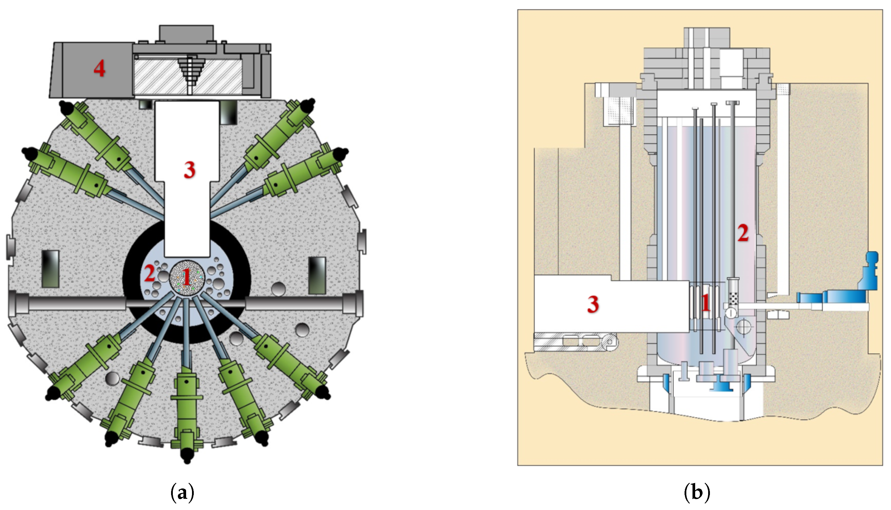
Figure 2.
Schematic of the proposed concept of UCN source at the WWR-K reactor.1 – SF 4He trap ( K); 2 – LD2 ( K); 3 – graphite ( K); 4 – Pb shield; 5 – reactor core; 6 – neutron guide; 7 – separating foil; 8 – heat-conducting wall.
Figure 2.
Schematic of the proposed concept of UCN source at the WWR-K reactor.1 – SF 4He trap ( K); 2 – LD2 ( K); 3 – graphite ( K); 4 – Pb shield; 5 – reactor core; 6 – neutron guide; 7 – separating foil; 8 – heat-conducting wall.
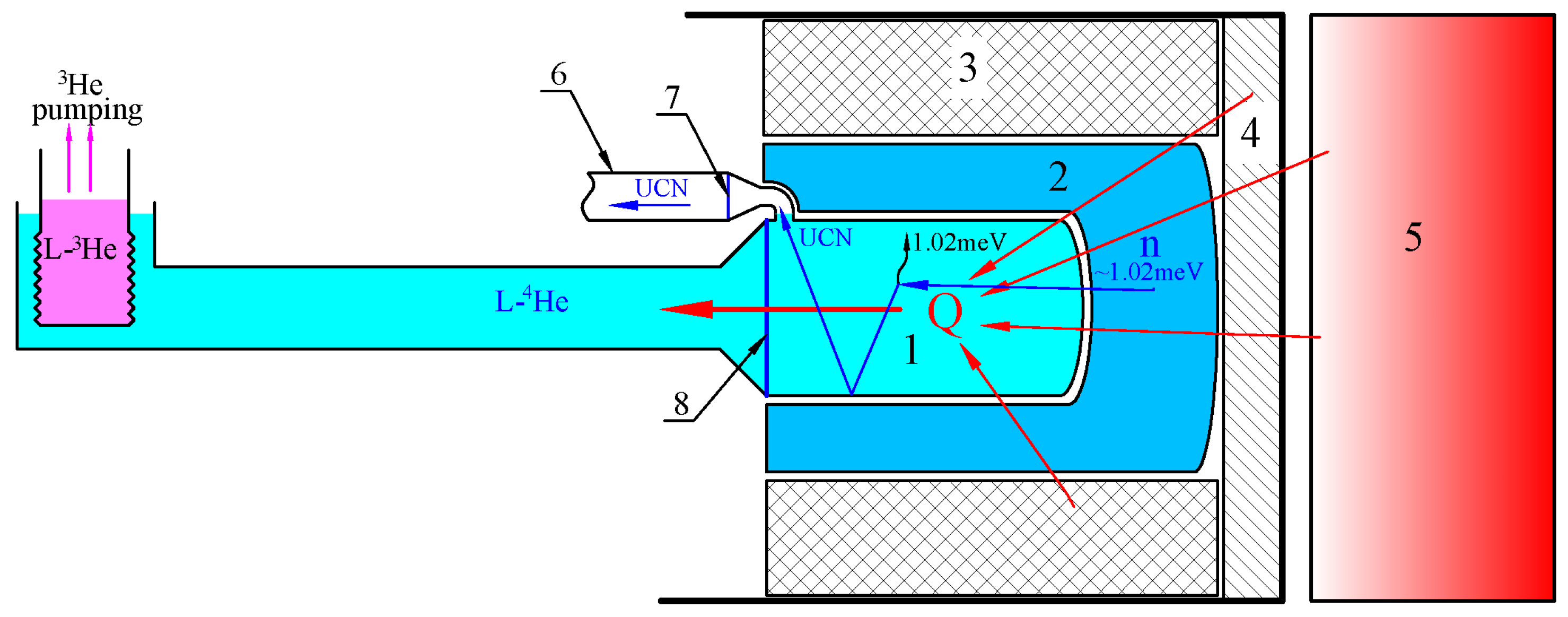
Figure 3.
Cross-section of the deuterium chamber: 1 – Volume containing liquid deuterium; 2 – Volume with superfluid helium; 3 – Helium cooling envelope; 4 – Deuterium feed and return lines; 5, 6 – Helium feed and return lines, respectively; 7 – Stiffening ribs.
Figure 3.
Cross-section of the deuterium chamber: 1 – Volume containing liquid deuterium; 2 – Volume with superfluid helium; 3 – Helium cooling envelope; 4 – Deuterium feed and return lines; 5, 6 – Helium feed and return lines, respectively; 7 – Stiffening ribs.
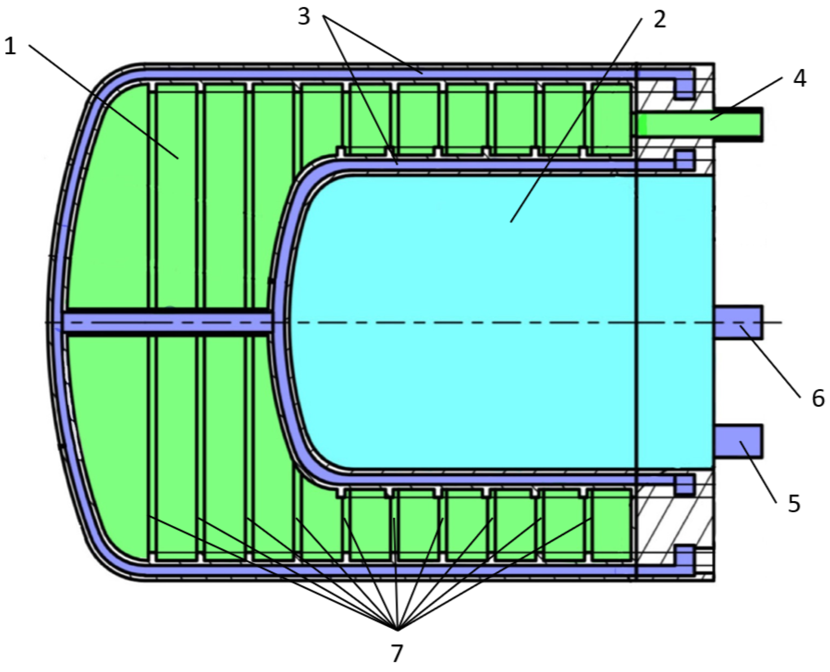
Figure 4.
Time evolution of deuterium temperature under heat load caused by failure of the helium cooling system.
Figure 4.
Time evolution of deuterium temperature under heat load caused by failure of the helium cooling system.
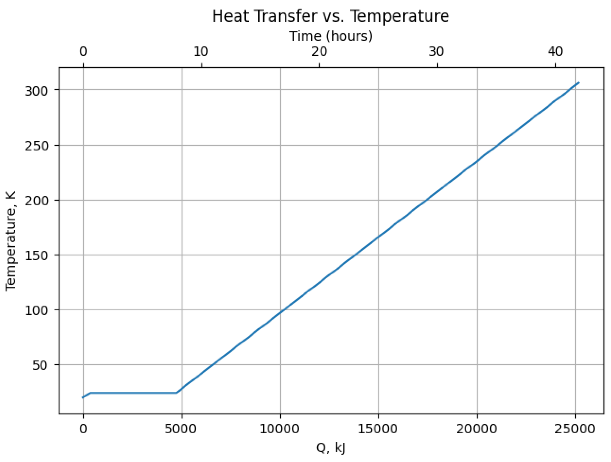
Figure 5.
Time evolution of Von Mises equivalent stress in the deuterium premoderator container walls during a cooling failure scenario. The stress is compared to the admissible limit to assess structural safety margins.
Figure 5.
Time evolution of Von Mises equivalent stress in the deuterium premoderator container walls during a cooling failure scenario. The stress is compared to the admissible limit to assess structural safety margins.
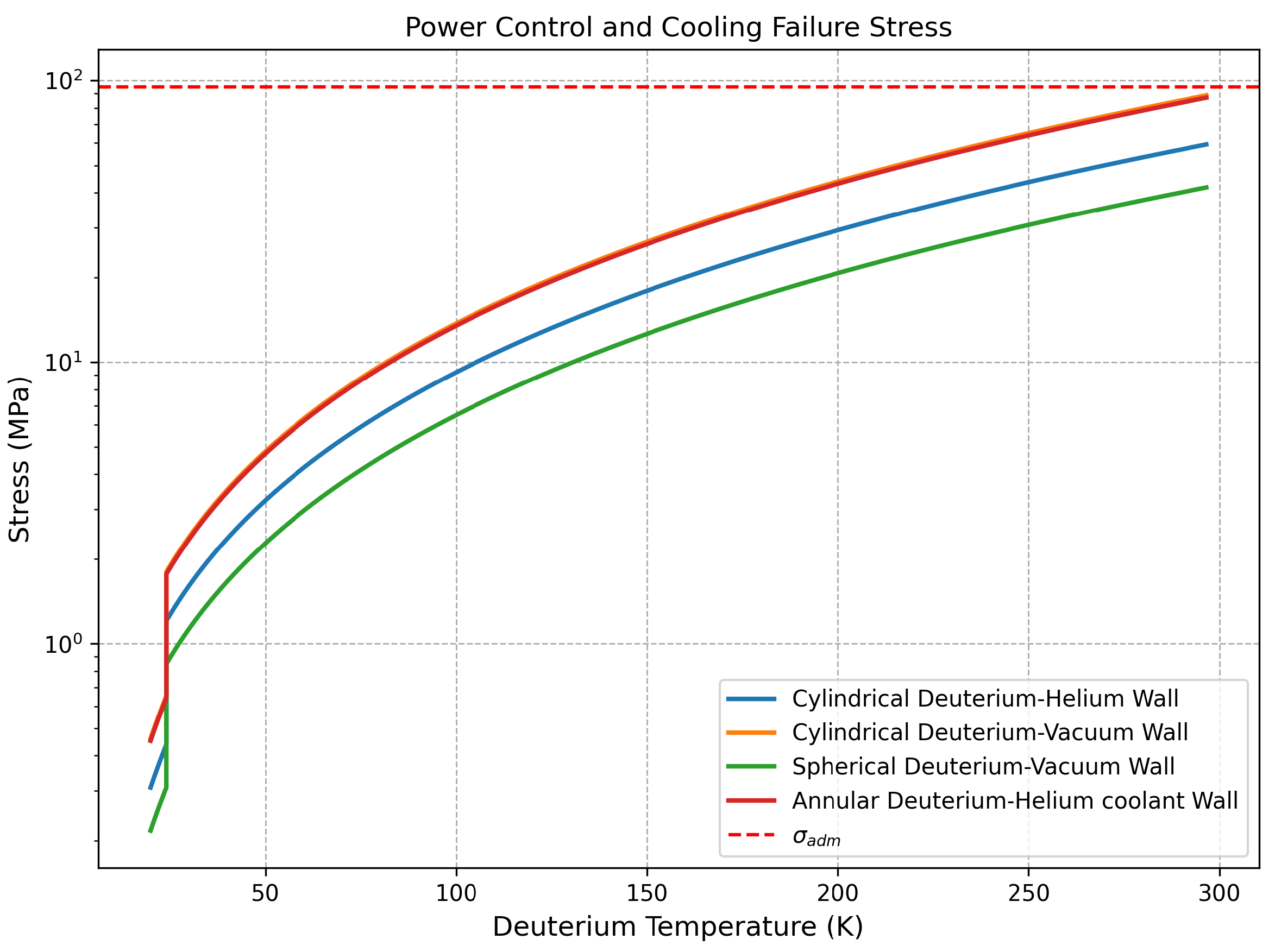
Figure 6.
Time evolution of heat transfer rates in the cylindrical and spherical surfaces during the vacuum loss scenario.
Figure 6.
Time evolution of heat transfer rates in the cylindrical and spherical surfaces during the vacuum loss scenario.
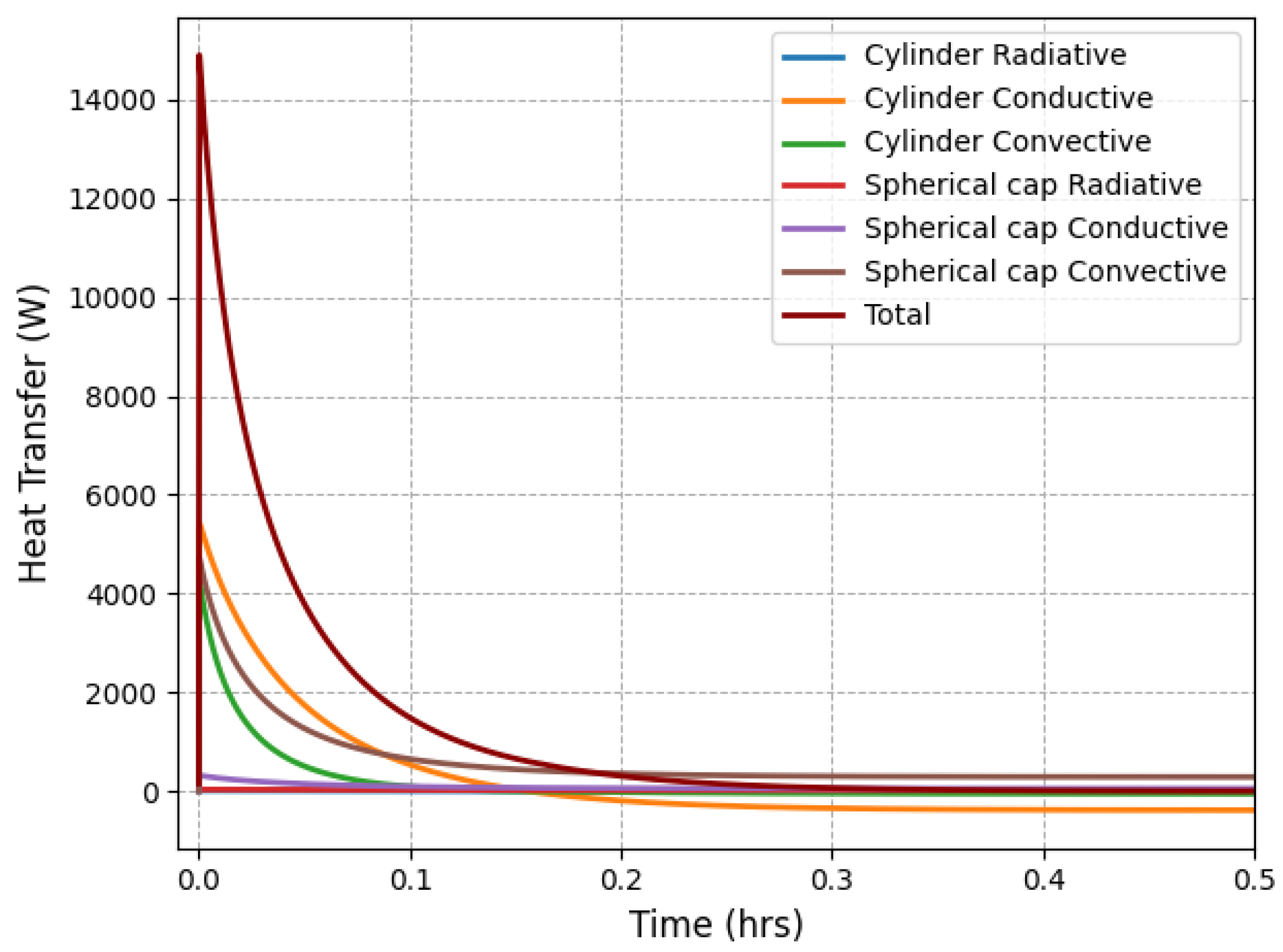
Figure 7.
Temperature evolution of the deuterium premoderator and surrounding container walls following vacuum loss.
Figure 7.
Temperature evolution of the deuterium premoderator and surrounding container walls following vacuum loss.
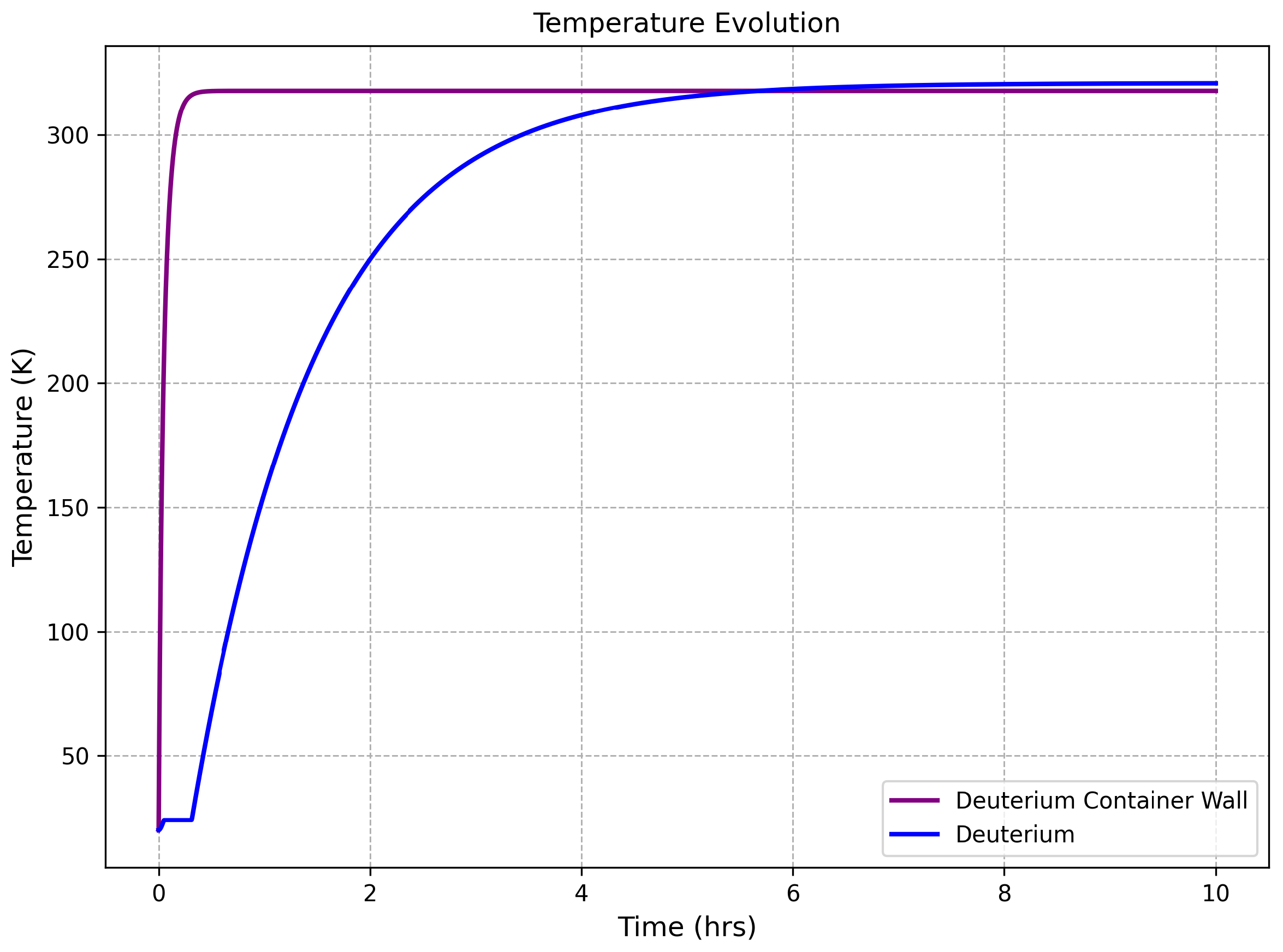
Figure 8.
Evolution of Von Mises equivalent stress in the deuterium container walls during air ingress vacuum loss.
Figure 8.
Evolution of Von Mises equivalent stress in the deuterium container walls during air ingress vacuum loss.
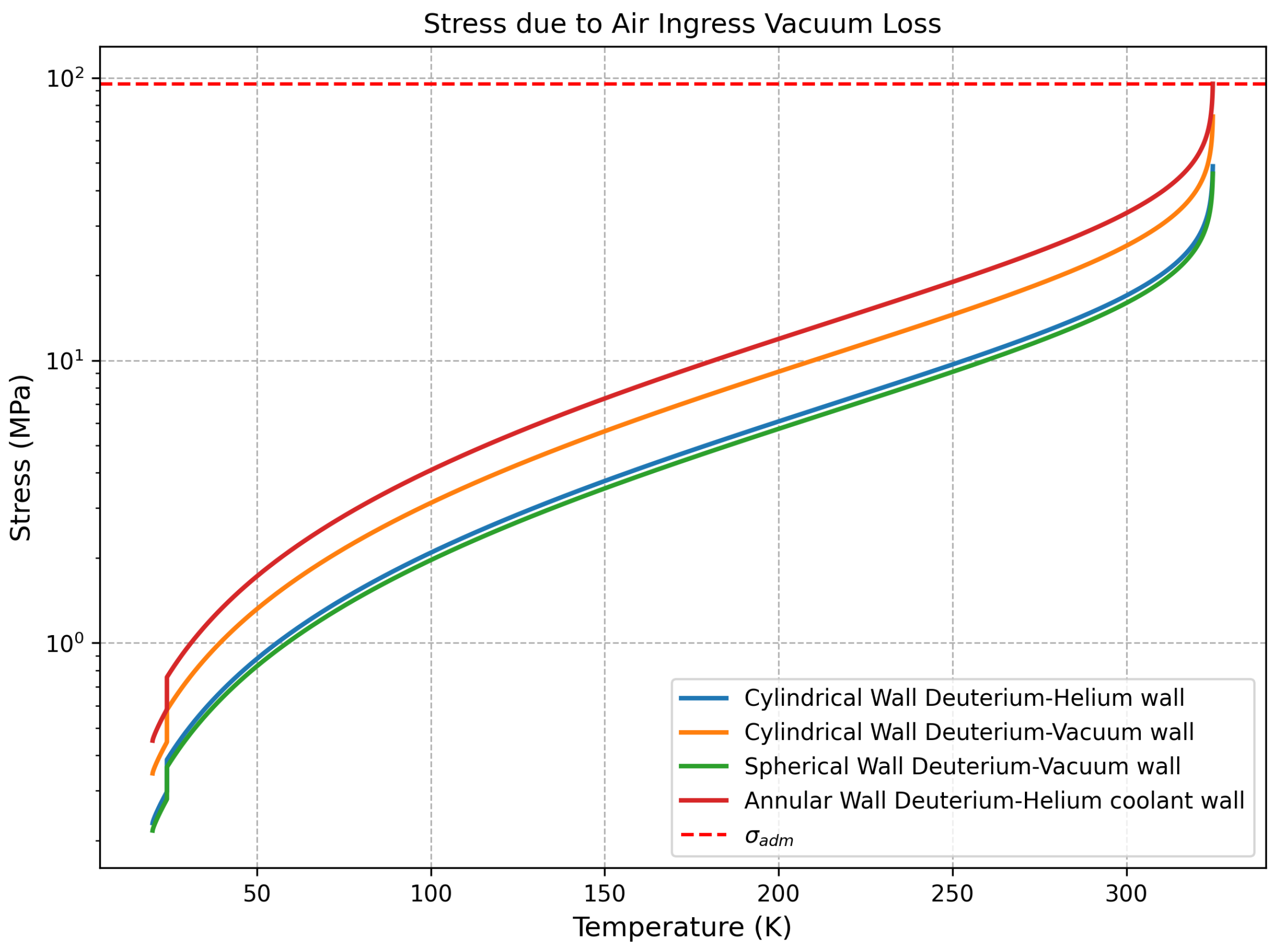
Figure 9.
Adiabatic isochoric complete combustion (AICC) results for deuterium-air deflagration. (a) AICC temperature versus air mass at fixed K. (b) Normalized pressure ratio versus air mass. (c) AICC temperature versus at stoichiometric mass. (d) Normalized pressure ratio versus .
Figure 9.
Adiabatic isochoric complete combustion (AICC) results for deuterium-air deflagration. (a) AICC temperature versus air mass at fixed K. (b) Normalized pressure ratio versus air mass. (c) AICC temperature versus at stoichiometric mass. (d) Normalized pressure ratio versus .
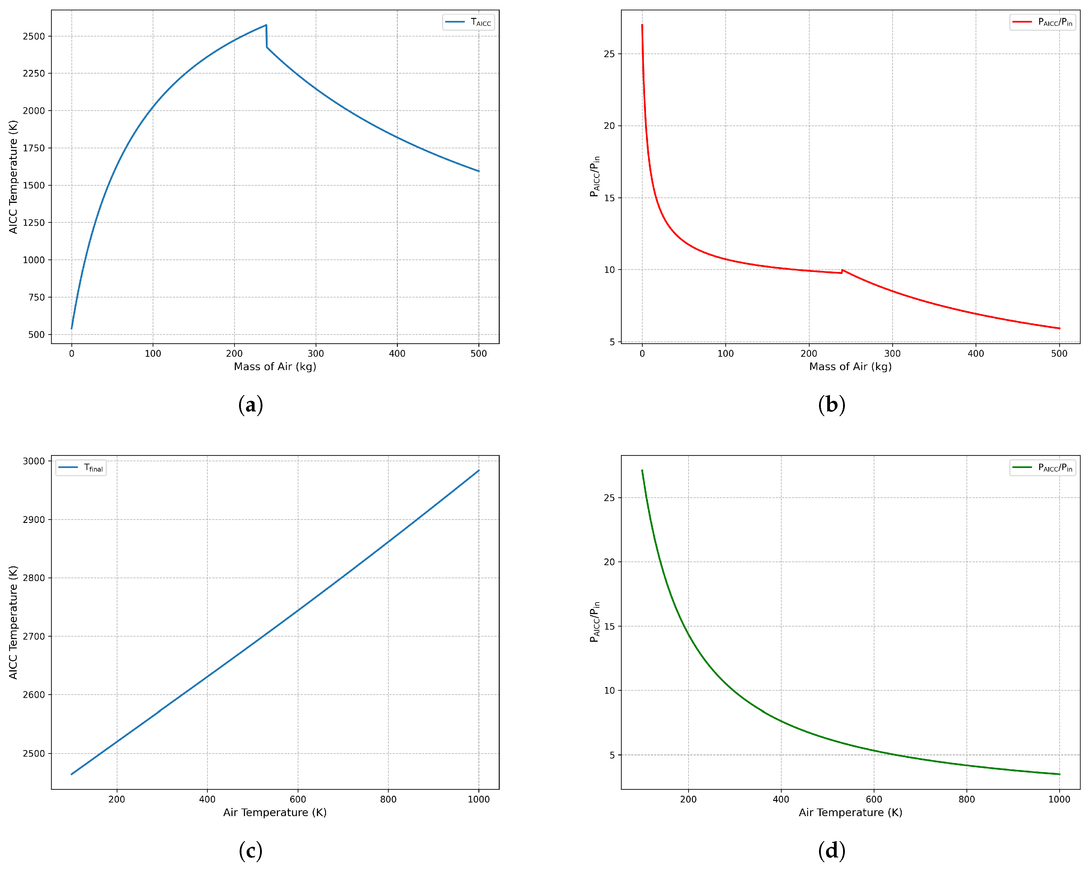

Table 1.
Deuterium properties.
| Property | Value |
|---|---|
| Pressure | 1.5 atm |
| Freezing Temperature | 18.73 K |
| Boiling Temperature | 24.12 K |
| Density of at saturation | 162.47 g/L |
| Heat of vaporization | 52.8 kJ/L |
| Mass | 14 kg |
| Molar Mass | 4.0282 g/mole |
| Specific heat of liquid at 20 K | 6.3 J/g K |
| Specific heat of gas at 273.15 K | 5.1847 J/g K |
Table 2.
Energy and time required for deuterium to reach various thermal states during a cooling failure scenario.
Table 2.
Energy and time required for deuterium to reach various thermal states during a cooling failure scenario.
| Temperature | Energy | Time |
|---|---|---|
| 24.1 K (liquid) | 371 kJ | 0.6 hrs |
| 24.1 K (gas) | 4732 kJ | 7.9 hrs |
| 300 K (gas) | 24762.3 kJ | 41.3 hrs |
Table 3.
Stress results under detonation pressure loading ( MPa).
| Component | Geometry | Wall thickness | Stress (MPa) | Status |
|---|---|---|---|---|
| Inner deuterium vessel (Aluminum) |
Spherical | 3 mm | 418.6 | Exceeds |
| Outer deuterium vessel (Aluminum) |
Spherical | 2 mm | 612.5 | Exceeds |
| Vacuum vessel (Aluminum) |
Spherical | 9 mm | 89.6 | Within limits |
| Lead shielding disk (Lead) |
Planar plate | 100 mm | 147.7 | Exceeds |
Disclaimer/Publisher’s Note: The statements, opinions and data contained in all publications are solely those of the individual author(s) and contributor(s) and not of MDPI and/or the editor(s). MDPI and/or the editor(s) disclaim responsibility for any injury to people or property resulting from any ideas, methods, instructions or products referred to in the content. |
© 2025 by the authors. Licensee MDPI, Basel, Switzerland. This article is an open access article distributed under the terms and conditions of the Creative Commons Attribution (CC BY) license (http://creativecommons.org/licenses/by/4.0/).
Copyright: This open access article is published under a Creative Commons CC BY 4.0 license, which permit the free download, distribution, and reuse, provided that the author and preprint are cited in any reuse.


