Submitted:
17 November 2025
Posted:
27 November 2025
You are already at the latest version
Abstract
We report a novel compact nuclear fusion concept based on a 20 MeV tabletop electron storage ring (ESR), which electrostatically confines and accelerates deuterium and tritium ions to fusion-relevant energies. The ESR generates a relativistic potential well exceeding 500 kV, capable of trapping high-density ion populations. The 500keV potential also enables ion heating above 50 keV to initiate (d-t) fusion. Analytical calculations and simulations suggest that a confined ion population of 10^17 within a volume of 1.25 × 10^-5 m^3, corresponding to a density near 10^20/m^3 is shown to produce fusion power exceeding 2 MW. This ESR-based approach offers a potential pathway toward compact, efficient, and modular fusion power systems.
Keywords:
tabletop electron storage ring
; nuclear fusion
; ion trap
; electrostatic potential generated by relativistic ESR
; ion density
; beam structure
; special relativity
; ionization cross-section
; fusion reaction cross-section
1. Introduction
1.1. Background of Fusion Research
Contemporary nuclear fusion research is primarily focused on large-scale magnetic confinement systems such as tokamaks [1,2], which require plasma temperatures exceeding one billion degrees Celsius, large confinement volumes, necessary use of superconducting magnets and input powers of nearly 100 MW resulting in a quality factor of 10 to generate 500MW. While these systems represent significant scientific progress, they are extremely complex and costly to construct and operate.
1.2. Motivation for Electrostatic Confinement Approach
In contrast, we propose a fundamentally different approach based on relativistic electrostatic confinement using a tabletop electron storage ring (ESR). This method leverages the intense electric fields generated by relativistic electron beams to form deep electrostatic potential wells exceeding 500 kV, capable of radially confining deuterium d and tritium t ions. In this configuration, deuterium and tritium ions are radially confined by the 20 MeV relativistic electron beam, allowing the ion density to increase to the range through repeated ionization events. The neutron energy released from fusion reactions is absorbed in a surrounding water layer that serves as the thermalization and heat extraction system. The system is estimated to achieve an energy gain factor Q>50, enabling 2MW-class fusion output with relatively modest input power. Fusion is initiated in a compact system under room temperature; thus, the setting of the system is possible in a city or beside a factory.
2. Materials and Methods
2.1. Features of the MIRRORCLE-20SX ESR
The electron storage ring (ESR) to be used is MIRRORCLE-20SX (Figure 1), which was developed by Photon Production Laboratory Ltd. [6] 20 years ago. It features a 20 MeV electron beam and an exact circular orbit with a radius of 15 cm and an outer diameter of 80 cm, utilizing a weak focusing magnet configuration. Originally designed for applications such as synchrotron radiation [3] and extreme ultraviolet (EUV) photon generation [4], this device exhibits high beam stability, low emittance, and precise control over beam dynamics [5].
The characteristics of this ESR make it well suited for producing intense space charge fields, enabling the formation of a relativistic electrostatic potential well around the electron beam orbit. In this work, we exploit this unique feature to confine high-density deuterium and tritium ions, with the goal of initiating and sustaining nuclear fusion reactions.
2.2. ESR Configuration
An electron beam is injected into the ESR from an electron accelerator such as microtron [3]. Each injection delivers a 1 μC electron pulse, equivalent to approximately 10^13 electrons. This results in a circulating beam current of about 300 A around the 15 cm radius orbit. Since the beam travels a 1-meter-long path repeatedly at the speed of light (3 × 10^8 m/s). It takes 3.3 ns for one circulation.
The observed beam profile has a diameter of 5 mm, as shown in Figure 2. Initially the beam spread by 20mm, and due to radiation damping [13] beam size decreased to 5mm diameter. Although radiation damping is generally weak in low-energy storage rings, the observed beam contraction from 20 mm to 5 mm is attributed to energy loss through interactions with residual gas, which effectively provides a damping mechanism under the operating conditions. In this regime, beam energy loss is dominated by collisional interactions with the residual gas rather than by synchrotron radiation.
2.3. Ionization of Deuteron and Triton
To convert the ESR into a fusion reactor, we operate ESR at a vacuum pressure of 10^-4 Torr of deuterium and tritium gas and trap the resulting ions in the electron beam. Within 0.5 m sec, approximately 10^13 ions are generated. By repeating this injection process at 1 kHz, up to 10^17 ions can be stored, achieving an ion density of 10^20 ions/m^3. The volume occupied by the trapped ions is approximately equal to the beam volume, calculated as π × (5 mm) ^2 × 1 m = 7.85 × 10^-5 m^3. As circulating electrons collide with the fuel gas and gradually decay, the number of trapped ions increases through ionization. The rate of beam decay and ion accumulation, denoted here by τ, is determined by the ionization cross-section σ and gas density dm = 3.22·P (with P in Torr), using the relation [7];
τ = 1 / (dm · σ · β · c)
For hydrogen gas at 10^-4 Torr, this yields τ ≈ 0.5 m sec.
2.4. Simulation of Ion Storage and Beam Decay
Simulation results are shown in Figure 3. Ion accumulation proceeds rapidly, reaching 10^13 ions within milliseconds as shown in the red line. Beam decays in the blue line. The electron beam decays but ions stay in the electron beam and are accumulated. While ions gain kinetic energy through collisions with the relativistic electrons, their resulting drift velocities remain on the order of centimeters per second, consistent with the low effective ion temperature in the early phase of accumulation. Although the growing ion population tends to neutralize the electron beam, the fusion reactions begin within a few tens of microsec at the density 10^17/ m^3 and consume the ions, preventing significant beam neutralization.
2.5. Terminate the Neutralization Effects
We understand that when the number of ions increases and approaches the number of circulating electrons, the neutralization effect occurs and terminates ion trapping. However, we recognize that the (d, t) fusion reaction begins when the accumulated ion number is 10^13, corresponding to a density of 8x10^17/m^3.
The fusion reaction rate R [7] is given by , where for 50 keV ions.
The fusion reaction time is given by ,
The calculated is about 10μs. Accordingly, each fusion event produces a 3.5 MeV alpha particle that rapidly leaves the trapping region, effectively removing positive charge and thereby mitigating beam neutralization. We conclude that the occurrence of fusion reactions mitigates the neutralization effect.
2.6. Steady Electrostatic Potential Confining Ions in Relativity Regime
To quantify the relativistic electrostatic potential well generated by the circulating electron beam [11], we model the potential voltage Φ(r) as a function of radial distance r. Assuming a uniform cylindrical electron beam distribution, the potential is given by:
where: λ is the linear charge density I/eβc, ε₀ is the vacuum permittivity, a is the beam radius, R is the chamber radius, γ is the Lorentz factor. The relativistic factor modifies the space-charge potential, reducing the classical Coulomb repulsion and allowing a deeper and more stable trapping well to form. In Figure 4, we assume beam current 1000A the chamber size R=20 cm, γ= 40 for 20 MeV, and a=5 mm.
Φ(r) = (λ / 4πε₀) (1 − (r² / a²)) · γ for r ≤ a
Φ(r) = (λ / 2πε₀) ln (R / r) · γ for r > a
Figure 4 presents the spatial profile of the electrostatic potential (a) and electric field (b) induced by the space charge of the relativistic electron beam. Within the 5 mm beam radius, the potential is approximately parabolic and the electric field scales linearly with radius. Beyond the beam boundary at 5 mm. The relativistic correction significantly enhances the potential depth, allowing for stable ion trapping without overheating. Simulations indicate that ions preferentially accumulate near the beam boundary, where the radial electric-field gradient is strongest.
The calculated potential depth 550 keV is quite large. Factor γ is helpful. This voltage is enough to capture ions and gain energy vertically against the beam. When ions move toward the beam center the collision between ions happens and fuses. This is a great advantage of using the relativistic electron beam compared with the TOKAMAK type reactor.
2.7. Acceleration Mechanism
The trapped ions undergo radial confinement within the potential well and exhibit axial motion under the influence of the E x B drift [12].
The kinetic energy of ions is critical in determining the achievable fusion yield. Initially, ions gain energy through head-on collisions with the circulating relativistic electron beam. The expression for the ion kinetic energy is obtained from relativistic binary-collision kinematics as derived in Ref. [11].
where γ is the Lorentz factor, mₑ is the electron mass, M is the ion mass, vₑ is the electron velocity. This yields a maximum ion kinetic energy of approximately 21 keV on average, which is insufficient to sustain fusion reactions, since around 50 keV is required for (d, t) fusion. However, additional heating is introduced by the 550 kV vertical electron beam potential discussed in sec. 2.7. Ions are accelerated by this potential and oscillating against the beam center.
K = [2γ²mₑ²c²vₑ²] / [(mₑ + M) ² + 2M (γ − 1) mₑ]
3. Results
3.1. Fusion yield [8,9,10]
Monte Carlo simulations and analytical estimates indicate that a population of 10^17 ions can be confined within a volume of 1.25 × 10^-5 m^3 near the electron beam, corresponding to an ion density of approximately 8 × 10^21 ions/m^3.
Using the Bosch-Hale parametrization [7], the fusion reactivity at 50 keV is approximated as ⟨σv⟩ = 10^-21 m^3/s. Assuming equal deuteron and triton densities, , the reaction rate becomes .
Each (d, t) fusion event releases 17.6 MeV (2.82 × 10^-12 J), yielding a total thermal power output of P = 8 × 10^17 × 2.82 × 10^-12 = 2.26 MW
3.2. Synchrotron Type Fusion Reactor Design and Advantages for Potential Applications
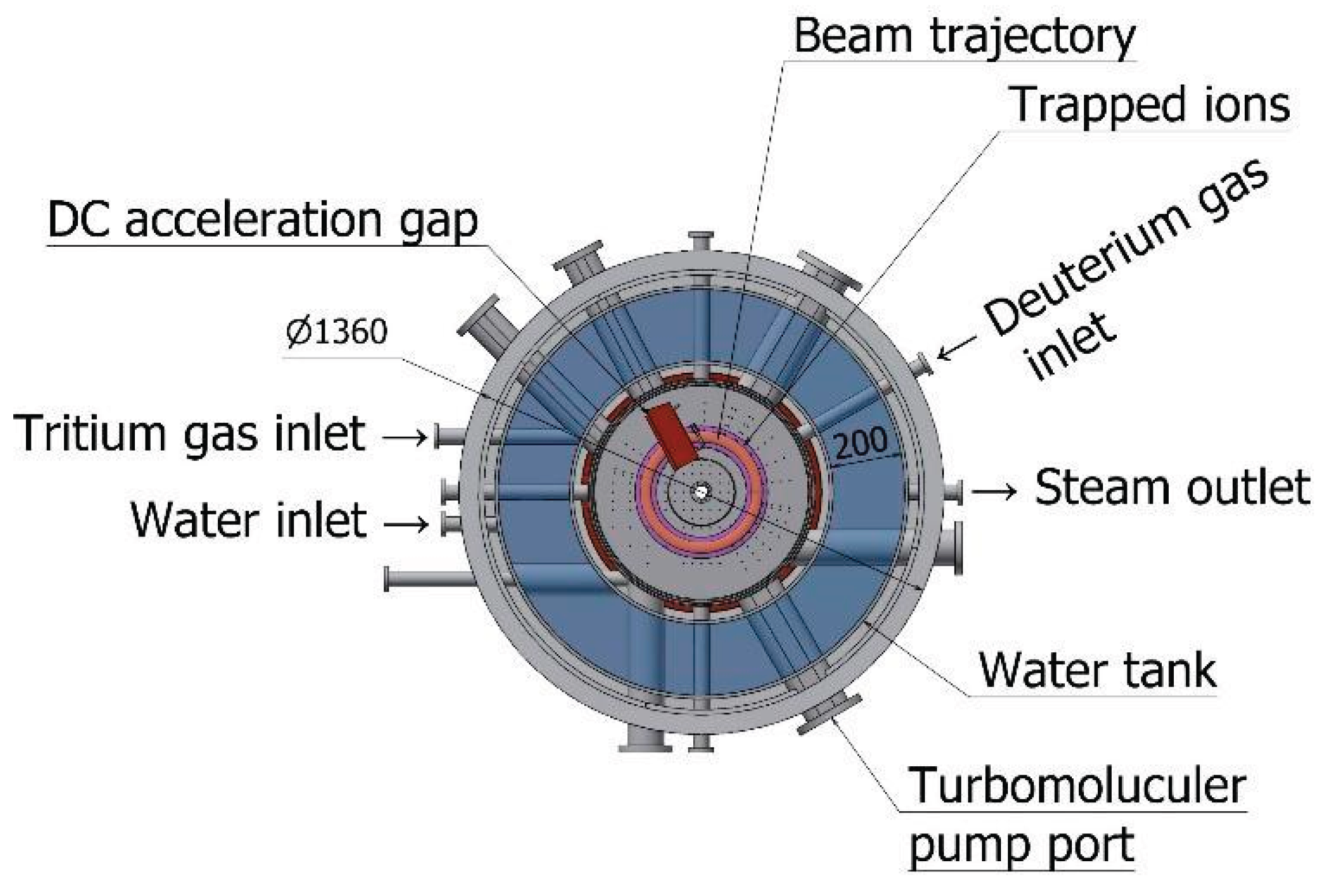
To convert the ESR into the fusion reactor, we make space for a water tank to thermalize neutron energy as shown in Figure 5. The generated steam is supplied to an electricity generator. We name this system Synchrotron Type Fusion Reactor (STFR)
The ESR-based fusion system offers several advantages over conventional plasma fusion approaches:
- -
- Compact and modular design (tabletop-scale implementation)
- -
- The storage-ring system operates with an estimated electrical input of approximately 30 kW, including electron-beam generation.
- -
- Heat from moderated fusion neutrons is transferred to a water-based thermal system, which provides conventional thermal-to-electric conversion.
- -
- -Electrostatic confinement is made by a normal conducting magnet.
These features also enable applications in compact neutron sources, energy research prototypes, and hybrid fusion-fission systems.
Challenges remain, particularly in increasing the fuel injection rate, scaling the ESR energy beyond 20 MeV (e.g., to 50 MeV), and ensuring long-term stability of beam-ion interactions. Continuous operation and energy recovery methods also require further investigation.
3.3. Conclusion
We have introduced a novel method for achieving compact nuclear fusion using relativistic electrostatic confinement in a tabletop electron storage ring (ESR). Simulations and analytical calculations demonstrate that megawatt-class (d, t) fusion power can be produced within sub-liter volumes. This approach shows promise as a low-cost, scalable, and efficient alternative to traditional large-scale plasma fusion reactors.
Acknowledgements
The author acknowledges sincere thanks to the staff of Fusion Harmony Ltd. and Mirrorcle Analysis Centre Ltd. which provide access to the MIRRORCLE electron storage ring.
References
- ITER Organization, https://www.iter.org/.
- J. Wesson, “Tokamaks”, Oxford University Press, 2011.
- H. Yamada et al., “Tabletop Synchrotron Light Source,” “Comp. Biomed. Phys.”8 (2014): 43–65.
- H. Yamada et al., “EUV Source by Tabletop Storage Ring,” J. Micro/Nanolith. MEMS MOEMS 7.4 (2008): 043004.
- H. Yamada, “Smallest Electron Storage Ring for X-ray Production,” J. Synchrotron Rad. 5 (1998): 1326–1329.
- Photon Production Laboratory Ltd., https://www.photon-production.co.jp/en/index_e.htm.
- H.-S. Bosch and G. M. Hale, “Improved Formulas for Fusion Cross Sections and Thermal Reactivities,” Nucl. Fusion 32.4 (1992): 611. [CrossRef]
- L. C. Steinhauer, “The Electron Ring as a Fusion Reactor,” Nucl. Fusion 14.5 (1974): 681–690.
- M. Nishiuchi et al., “Ion Acceleration with Relativistic Electron Rings,” Phys. Plasmas 28 (2021): 123104.
- S. Atzeni and J. Meyer-ter-Vehn, “The Physics of Inertial Fusion”, Oxford University Press, 2004.
- J. D. Jackson, “Classical Electrodynamics”, 3rd ed., Wiley, 1998.
- F. F. Chen, “Introduction to Plasma Physics and Controlled Fusion”, 2nd ed., Springer, 1984.Surname A and Surname B 2009 Journal Name 23 544.
- in a book, Introduction to Accelerator Dynamics, Cambridge University Press, chapt. “Synchrotron Radiation, – Classical Damping”, 2017, pp. 116-130.
Figure 1.
Overview of the MIRRORCLE-20SX. It is composed of an injector microtron (top) and storage ring (bottom) placed vertically The entire system is installed in the 3x5 m^2 and 2-m-high banker. X-ray, EUV, FIR beams are extracted.
Figure 1.
Overview of the MIRRORCLE-20SX. It is composed of an injector microtron (top) and storage ring (bottom) placed vertically The entire system is installed in the 3x5 m^2 and 2-m-high banker. X-ray, EUV, FIR beams are extracted.
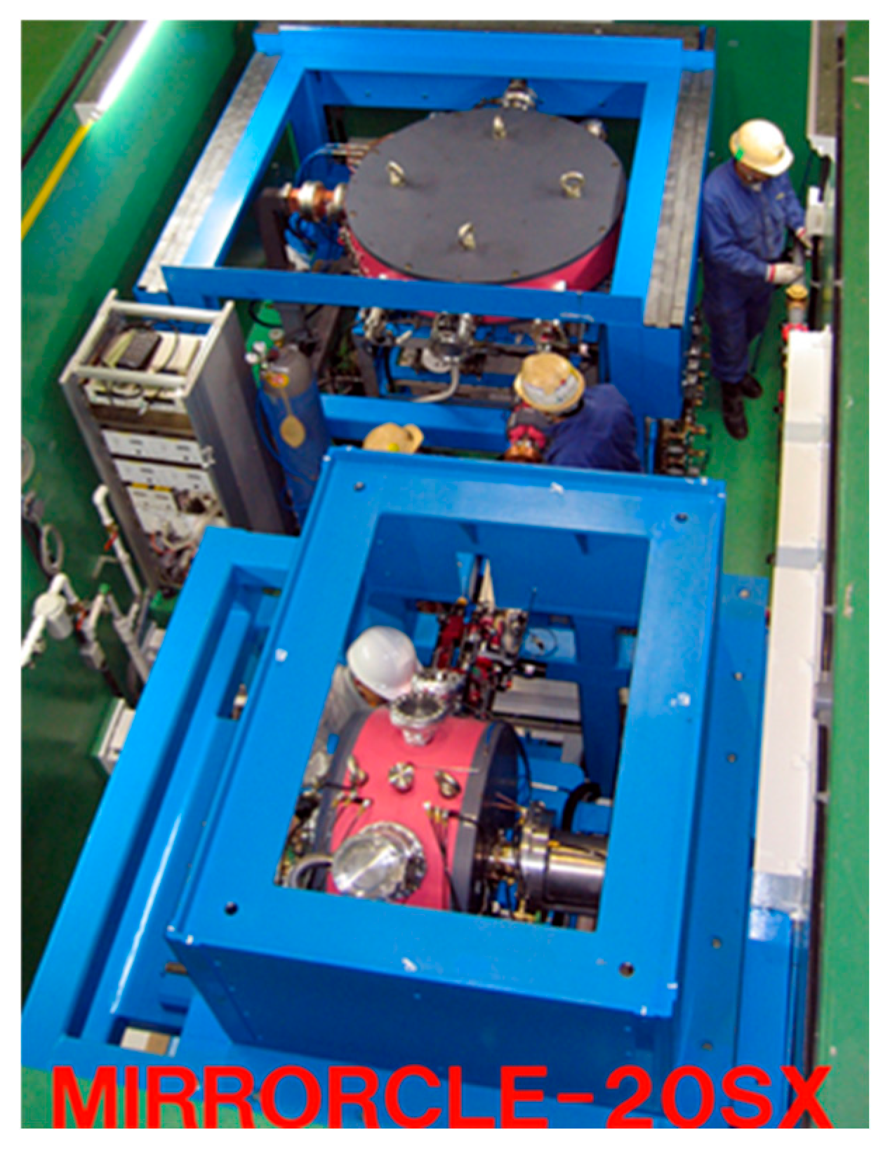
Figure 2.
The observed beam profile [3]. (Upper left) During the beam injection, the beam spreads to a width of 20 mm, (upper middle and right, lower left and middle) Due to the radiation damping, beam focusses into 5 mm diameter, and (lower right) the result by the injection at 70 Hz.
Figure 2.
The observed beam profile [3]. (Upper left) During the beam injection, the beam spreads to a width of 20 mm, (upper middle and right, lower left and middle) Due to the radiation damping, beam focusses into 5 mm diameter, and (lower right) the result by the injection at 70 Hz.
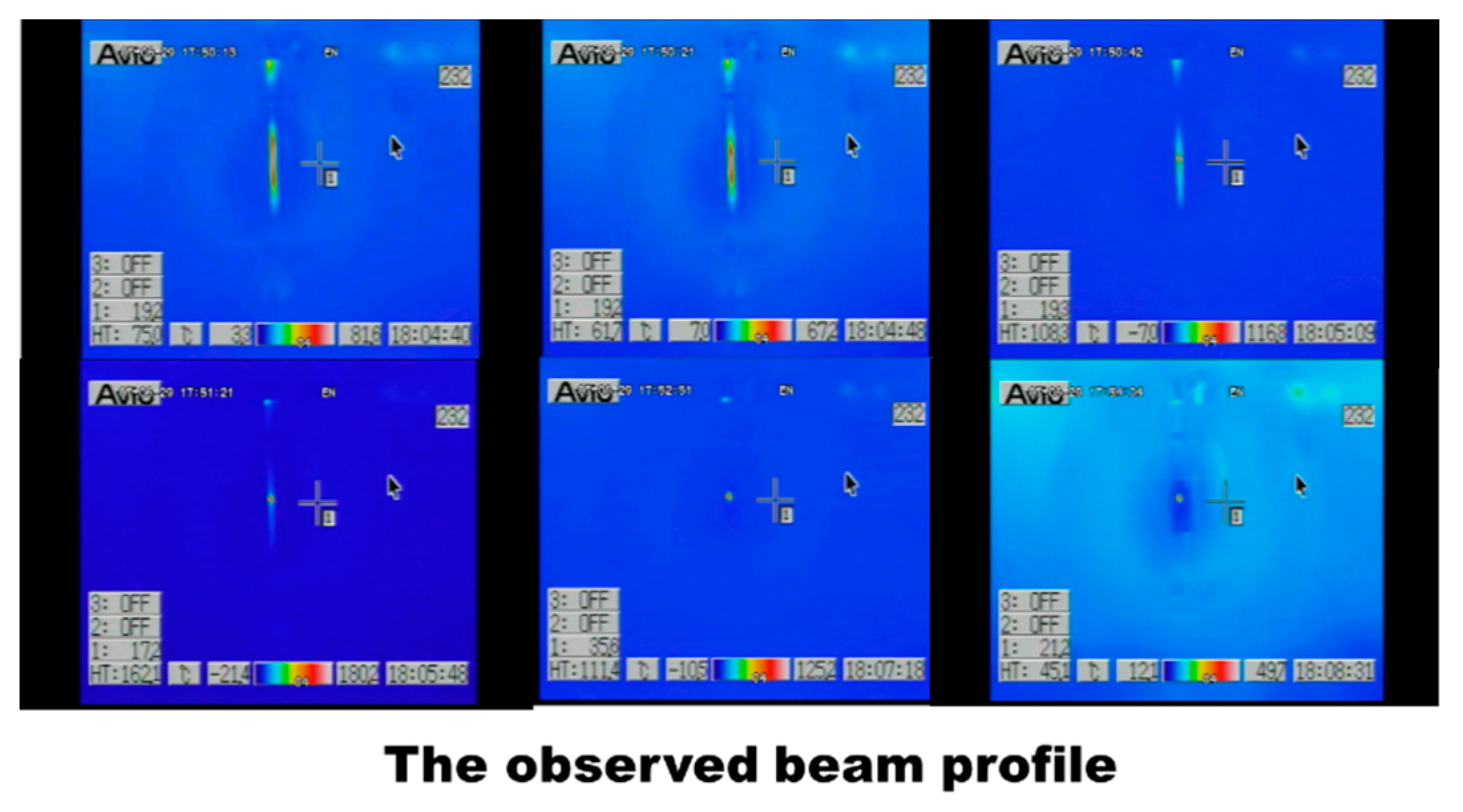
Figure 3.
This figure shows repeated beam injection in 1m sec intervals and the exponential decay in circulating electrons as a result of ionization collisions with fusion gases. Simultaneously, the number of fusions increases proportionally, demonstrating the inverse relationship between beam attenuation and ion generation. The graph captures the characteristic time scale for 1/e decay of the electron current and illustrates the resulting cumulative ion population over time. This provides a direct measure of the ESR's effectiveness as an ion source.
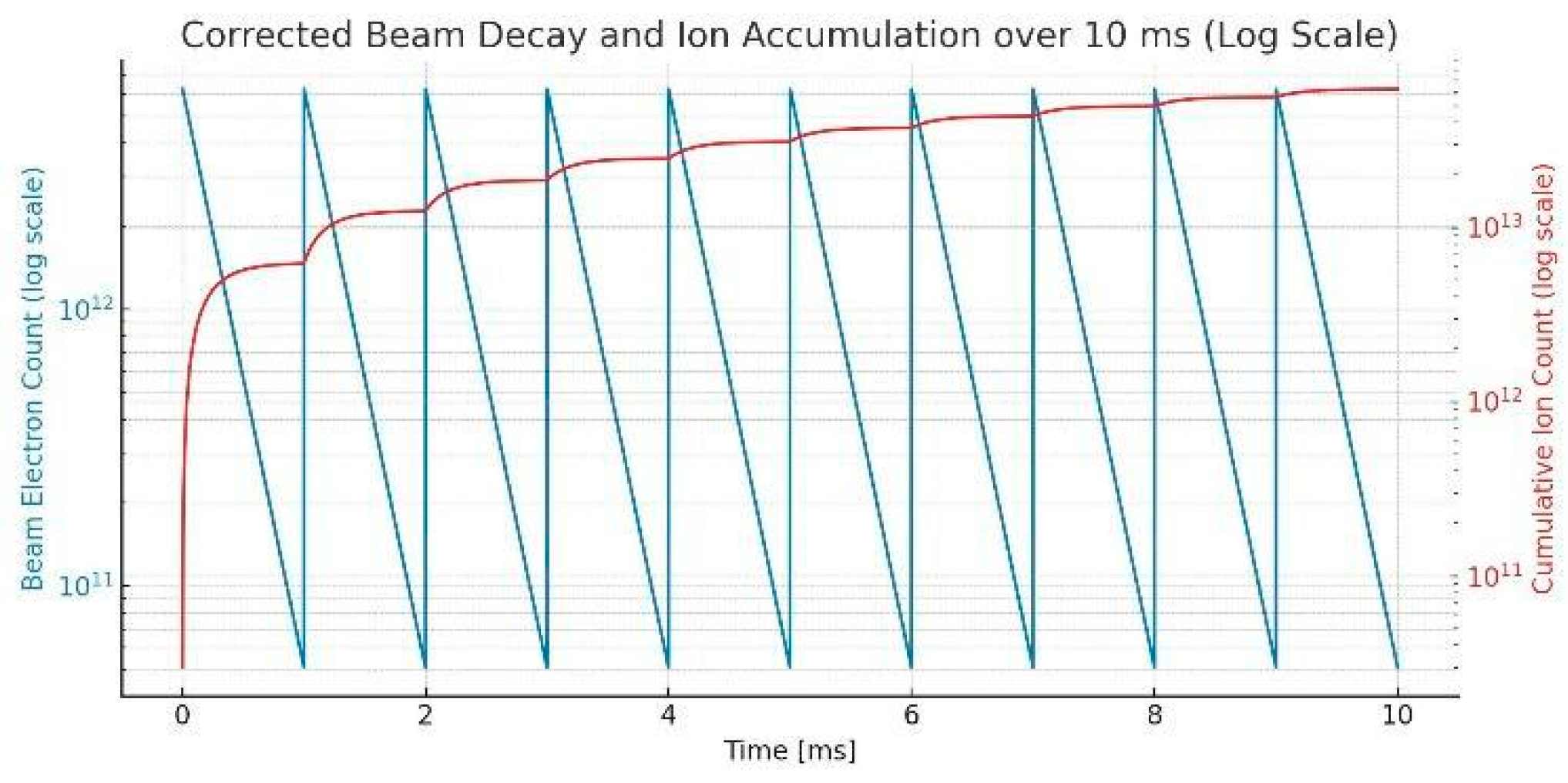
Figure 4.
This formulation follows classical electrodynamics as described in [11]. The calculated potential and electric field distributions are shown in Figure 4(a) and 4(b), respectively. A potential well depth of 550 kV is sufficient to trap ions with kinetic energies up to 100 keV. Notably, the ions are observed to localize near the edge of the beam, where the electric field gradient is steepest.
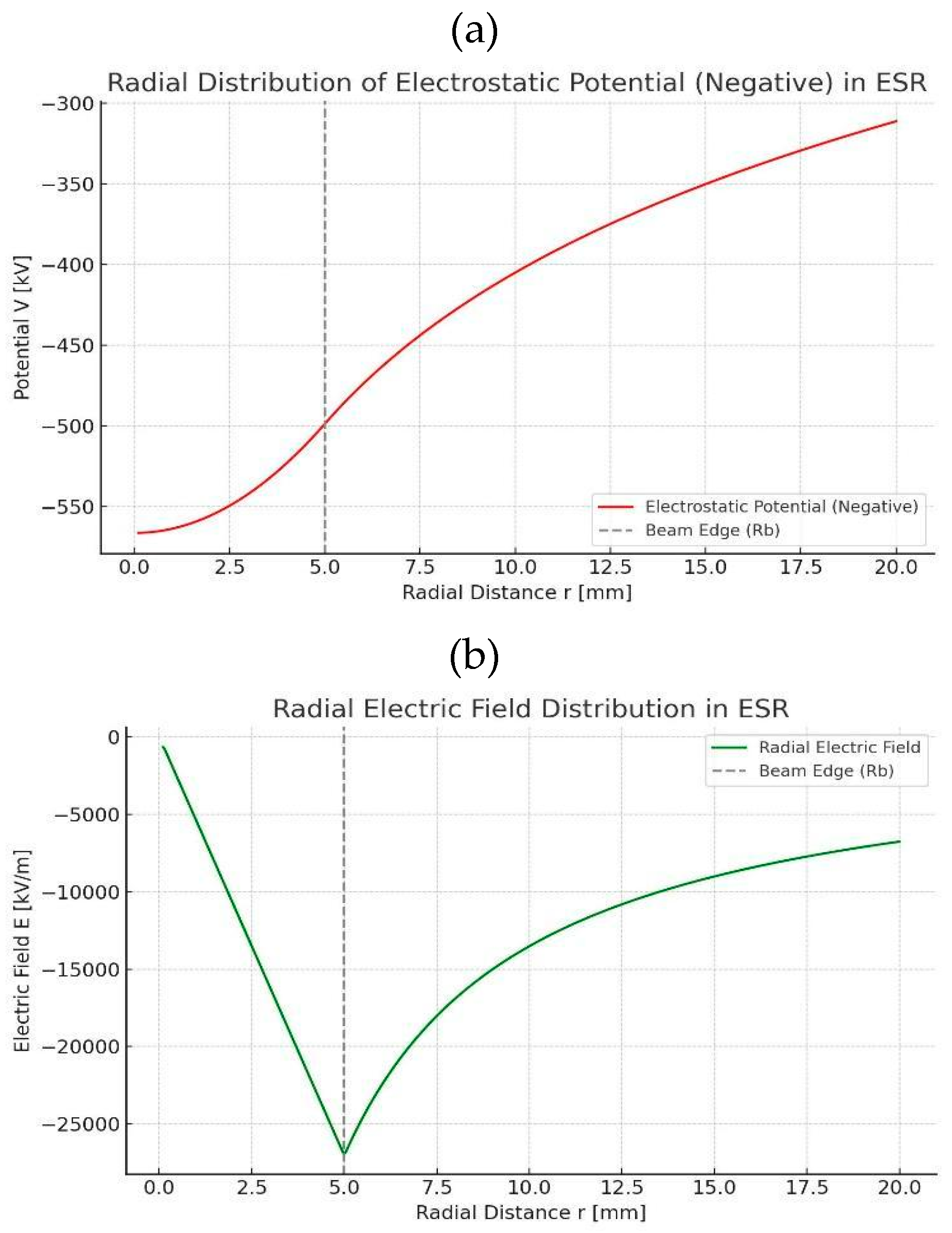
Figure 5.
This figure illustrates the structural concept of the STFR head, where a 20 MeV electron beam circulates within a compact, 1.36-meter-wide storage ring. The beam generates a relativistic electrostatic potential well, which traps the ionized deuterium and tritium gas introduced at 10^-4 Torr pressure. Stationary tritium gas is positioned adjacent to the ion trap region to enable (d, t) collisions. The ESR configuration allows for repeated interactions between electrons and deuterium atoms, enhancing ionization and confinement efficiency.
Disclaimer/Publisher’s Note: The statements, opinions and data contained in all publications are solely those of the individual author(s) and contributor(s) and not of MDPI and/or the editor(s). MDPI and/or the editor(s) disclaim responsibility for any injury to people or property resulting from any ideas, methods, instructions or products referred to in the content. |
© 2025 by the authors. Licensee MDPI, Basel, Switzerland. This article is an open access article distributed under the terms and conditions of the Creative Commons Attribution (CC BY) license (http://creativecommons.org/licenses/by/4.0/).
Copyright: This open access article is published under a Creative Commons CC BY 4.0 license, which permit the free download, distribution, and reuse, provided that the author and preprint are cited in any reuse.


