Submitted:
20 November 2025
Posted:
21 November 2025
You are already at the latest version
Abstract
The presented problem considers the dynamic stability of a three-layered annular plate, whose
facings are made of functionally graded material in the radial direction. The
plate is subjected to linearly increasing forces over time, applied along the
plane of the facings at either the inner or outer edge. The effect of the
heterogeneity of the plate-facing material on the dynamic response is analyzed
in detail. The main parameters of the stability state, such as critical dynamic
loads, critical time, maximum deflection, and buckling mode are specifically
evaluated. The problem is analyzed using two approximation methods: the finite
difference method and the finite element method. Numerical calculations were
carried out on two tracks: using the author’s program after analytical
calculations and with the ABAQUS system. The final results show the importance
of modeling the plate with an appropriate material function that describes the
radial gradation of the material, affecting the plate’s dynamic stability
response and critical parameters.
Keywords:
three-layered annular plate
; composite plate structure
; functionally graded material facings
; dynamic stability
; finite difference method
; finite element method
1. Introduction
In the present work, a method for the calculation of composite annular plates with heterogeneous metal facings is proposed. Numerous analysis results are presented, with primary attention focused on the dynamic responses of plates under loads acting in the plane of the facings. The evaluation of the loss of plate stability, which is accompanied by a sudden change in the shape of the plate at a specific critical load, shows the sensitivity of the examined structure to its geometrical and material parameters. The application of a heterogeneous structure with smoothly functionally graded material of facings allows the construction of new plate structures with a classical three-layer layout, whose mechanical properties can fulfil the required specifications. By evaluating the buckling phenomenon for two material models, resulting from the radial distribution of the extreme material properties of steel and aluminium, a thorough numerical analysis and discussion of the obtained results have been conducted. The calculation results were obtained for two computational models: an analytical and numerical model based on the finite difference method (FDM), and a numerical model using finite elements. Special attention was given to the computational efficiency of combining analytical and numerical calculations through approximation methods, including orthogonalization and finite differences. The presented calculation techniques and evaluation of buckling behavior complement research in composite plates, creating opportunities for further exploration of structures tailored to specific requirements.
The search for new composite structures that meet technical requirements continues. Plates, including the annular plates examined in this work, are widely used construction elements in various industries, such as mechanical engineering, civil engineering, nuclear, and aerospace applications. Composite three-layered plates with a classic structure, composed of thin metal facings and a thicker foam core, have been extensively analyzed and applied in practice.
A growing expectation in many industrial sectors is the design of structures dedicated to precise, specific technical solutions. Predicted reactions of elements demonstrating enhanced capabilities of specially composed structures, compared to classical designs, directly fulfill this expectation.
The technical potential of such structures for three-layered annular plates can be realized through the use of heterogeneous elements. Radially variable material properties of the metal facings enable the construction of new layered plates. Recognition of their static and dynamic behaviors, to assess stability loss, is the focus of the research undertaken in this work. It should be emphasized that buckling studies of layered annular plates, including three-layered plates, are presented in numerous scientific works. Thematic groups can be distinguished based on the modeling and load conditions of the examined annular plates. Thermo-mechanical environments are dominant, and most studies focus on plates with transverse material gradation.
The nonlinear bending and post-buckling behavior of a functionally graded material (FGM) annular sector plate is presented in work [1]. The plate is composed of two materials: ceramic and metal, with material parameters continuously varying across the plate thickness. The effects of material and geometrical parameters on plate responses have been examined. Two kinds of boundary conditions have been applied. Numerical calculations were conducted using graded finite elements. The free vibration analysis of the annular sector plate is presented in work [2]. The plate is also composed of metal and ceramic. Two theories were used in modeling: first-order shear deformation and Love’s theory. The influence of different geometrical sector ratios and material parameters on the frequencies of the plate sector with various boundary conditions is presented. The dynamic analysis of bidirectional FGMs in a rotating annular plate with variable thickness, including the effects of geometric imperfections and different boundary conditions, is presented in work [3]. The FGM plate material parameters vary in both the radial and axial directions. The effect of specific geometrical ratios of the annular plate on low-velocity impact behavior is demonstrated through numerous results. Effects of thermo-mechanical loading, geometrical parameters, and boundary conditions on the large deflection behavior of annular and circular FGM plates are presented in paper [4]. The material grading through the plate thickness is expressed using a power law. Large deflections are derived from Karman’s equations, which include thermal relations. The frequency analysis of an FGM annular plate under hygrothermal effects, with graded material across the plate thickness, is presented in paper [5]. Finite element analysis was applied to clamped–clamped and clamped–free boundary conditions for the examined plate model. Free vibration analysis of FGM annular and circular plates is presented in paper [6]. Material parameters are distributed across the plate thickness according to the power law. The effects of graded material parameters and different geometrical measurements on the natural frequency values are examined. The static temperature analysis of a three-layered annular plate with heterogeneous facings made of material with radially variable parameters is considered in work [7]. Material properties are defined by specified exponent functions. The effects of material and geometrical parameters in two plate models, built using FDM and finite element methods (FEM), on the plate response in a thermal environment are shown. The influence of a time-dependent temperature field and the effect of a stationary temperature field on the stability of a three-layered annular plate are presented in works [8] and [9]. Temperature changes, expressed as gradients in the plate’s radial direction, are considered.
Complex loading fields, such as magnetic, electric, and piezo-magnetic, in addition to thermo-mechanical loads, provide additional effects that alter plate responses. The free vibration analysis of FGM annular plates integrated with piezo-magneto-electro-elastic layers is shown in paper [10]. The effect of temperature environments, corresponding to various plate parameters, has been examined. Stress and displacement analysis of annular FGP plates subjected to complex loads, including transverse mechanical and magnetic forces, is presented in work [11]. Both the elastic modulus and magnetic permeability coefficient vary across the plate thickness according to a power function. Functionally graded piezoelectric annular plates on Winkler foundations are investigated in work [12]. The free vibration problem has been solved semi-analytically.
The behavior of plate elements is also controlled by structural properties, such as porosity. Classical functionally graded annular and circular plates with porosity are examined in paper [13]. Three porosity models were assumed: uniform, O-shaped, and X-shaped. The analyses focus on the basic natural frequencies. The effects of material and geometrical parameters, as well as porosity distribution, on axisymmetric bending of FGM annular or circular microplates under thermal and mechanical loads are presented in paper [14]. Nonlinear finite element models with various porosity distributions have been examined.
Geometrical or material heterogeneity creates complex models that require specialized solution techniques. To understand not only the macro-scale impact of structures but also the influence of microstructure on plate responses, tolerance-based modeling techniques are used. These approaches are applied to various problems, including vibrations, stability, thermo-elasticity, heat conduction, and temperature-dependent behavior [15,16,17,18,19,20,21].
The dynamic stability of annular plates subjected to mechanical and thermal loads is presented in works [22,23,24,25,26]. The studies by Chen et al. [22] and Wang et al. [23] are exemplary, addressing the dynamic stability analysis of mechanically loaded sandwich annular plates. The dynamic stability of three-layered annular plates subjected to loads acting on the facings is presented in works [24] and [25]. Plate responses to forces increasing over time are analyzed depending on material, geometrical, and loading parameters. Two plate models, built using FDM and FEM, were examined. A buckling analysis of an FGM sandwich square plate with a metal core is presented in work [26], examining the effects of geometry, material parameters, and boundary conditions.
2. Problem Analysis
The object of this analysis is a three-layered annular plate, whose outer layers are made of FGM facings. The facings are composed of two metals: steel and aluminium. The material parameters change in the plate’s radial direction according to the functional relation given by Eq. 2 for two material models: St-Al, where steel is on the inner plate edge and aluminium on the outer edge, and Al-St, where aluminium is on the inner plate edge and steel on the outer edge (see Figure 1).
The analyzed examples include plates with FGM facings and homogeneous facings. The core material is homogeneous, made of polyurethane foam.
The plate is subjected to in-plane forces applied on the inner or outer edge of the facings. In the dynamic analysis, forces increase over time at a specified loading rate. The inner or outer edge is loaded with a uniformly distributed load, linearly increasing in time according to the following formula:
where p(t) is the compressive stress, s is the rate of plate loading, and t is time.
p=st ,
The main focus of this study is the plate’s buckling behavior. The plate is initially imperfect and can lose its stability in complex forms, with radial and circumferential buckling waves. The main observed examples are buckling with a half-wave in the radial direction and several waves in the circumferential direction, or the axisymmetric form without circumferential waves. Critical dynamic parameters, including the load pcrdyn, time tcr, deflection wcr, and mode m (defined by the number of circumferential waves), characterize the dynamic stability of the examined FGM plate. The moment of the loss of plate stability occurs when the speed of the point of maximum deflection reaches its first peak. This criterion for dynamic stability loss is presented in work [27].
The plate scheme is shown in Figure 2. The plate consists of three layers: FGM facings and a homogeneous core, forming a classical sandwich cross-section with thinner facings and a thicker core. The analyzed plate is slideably clamped at both the inner and outer edges.
3. Solution Procedure
The problem is solved using a combination of analytical and numerical calculations. It is based on the orthogonalization method for eliminating the angular variable θ (see Figure 2) and the FDM. The classical theory [28] of three-layered plate structures has been adopted. It is based on the assumptions of the broken-line hypothesis and the interaction of stresses between plate layers: normal stresses are carried by the facings, while shear stresses are carried by the core.
Additionally, an FEM plate model has been developed using the finite elements. The FEM plate structure corresponds to the classical formulation used for the FDM plate model.
3.1. Material Model
The radial changes of the FGM facing material are smooth and follow a power function:
where ri and ro are the inner and outer plate radii, r is the plate radius, and n is the power-law exponent.
The material parameters of the facings, such as Young’s modulus Er, Kirchhoff’s modulus Gr, Poisson’s ratio νr, and mass density μr depend on the plate radius r and the power-law exponent n. They are calculated according to the following equation:
where W1 and W2 are the values of the material parameters (Er, Gr, νr, and μr), VV is the rate of material variation in the radial direction, and W is the value of the facing material parameters at the plate point determined by the radius r. The distribution of material parameters in the facing plane is axisymmetric.
The facings are composed of two materials: steel, with Young’s modulus ESt = 210,000 MPa, and aluminium, with Young’s modulus EAl = 70,000 MPa, located at the selected edges of the plate. Between the edges, the facings’ material parameters vary according to the selected power-law exponent n (see Eq. 2), with n = 0.2, 0.5, 1, 2, 5. Figure 16 in Chapter 4.6 shows the distribution of Young’s modulus along the plate radius for three values of n (0.2, 1, 5) for the two plate material models St-Al and Al-St (see Figure 1). The effect of the material model on the stability results is discussed in this Chapter 4.6.
3.2. Technique of the Problem Solution Using the FDM
The solution process is based on the method presented in previous works [24,25,29,30]. The solution technique uses both analytical and numerical calculations. The analytical calculations lead to the main differential equation for the deflections of the analyzed composite plate in the dynamic problem:
where w is the total deflection, wd is the additional deflection, and δ, γ are the differences of radial u1, u3 and circumferential v1, v3 displacements of points on the middle surfaces of the facings, expressed by δ = u3 - u1 and γ = v3 - v1, respectively. N1 = 2Dr, , , are the rigidities of the plate facings; h is the total plate thickness, H′ = h′ + h2, where h′ is the facings’ thickness and h2 is the core thickness. Φ is the stress function, M = 2h′μr + h2, and μ2 is the core mass density.
Equation 4 was derived after formulating the dynamic equilibrium equations for each plate layer, assuming the deformation of the middle surface of the facings follows the nonlinear von Kármán theory, and describing the transversal geometry of the core deformation based on the linear broken line hypothesis. The equations of Hooke’s law were applied:
where σr is the radial stress, σθ is the circumferential stress, and τrθ is the shear stress.
Then, the resultant transverse forces in radial and circumferential directions and the resultant membrane forces expressed by the stress function were formulated, assuming the initial conditions that both the additional deflection wd and the speed of the additional deflection wd,t for time t = 0 are equal to zero. Boundary conditions are expressed for the total deflection w and the differences of displacements in radial δ and circumferential γ plate directions:
Loading conditions are defined for the plate edges: inner for radius ri or outer for radius ro, respectively:
The quantities d1 and d2 are equal to 0 or 1.
Plate geometry is modeled with the preliminary deflections. The shape is determined by the combination of the axisymmetric component and depends on the number m of circumferential waves [31,32]:
where the dimensionless predeflection is , the dimensionless plate radius is , ξ1 and ξ2 are numbers that calibrate Eq. 8, and η(ρ) = ρ4 + A1ρ2 + A2ρ2lnρ + A3lnρ + A4, with Ai satisfying the conditions of clamped edges.
The shape functions used in the solution of the problem include the additional deflection [31,32], the functions of the radial and circumferential facings displacements ,[24,25], and the stress function [31,32]:
where E is the established value of the Young’s modulus (ESt for the St-Al plate model or EAl for the Al-St model), , and m is the number of circumferential waves corresponding to the number of waves shaping the plate imperfection.
The solution technique uses the orthogonalization method to eliminate the angular variable θ, along with the FDM, which approximates the derivatives with respect to ρ using central differences at discrete points. The main equation of the system of differential equations has the following form [24,25,30]:
where the vectorcontains elements expressed by the derivative of the additional deflection with respect to time t, and the number K is given by. Here, K7 represents the rate of mechanical loading growth calculated as the quotient of s (see Eq. 1) to the assumed value of the critical static load pcr, with . The vector contains the additional deflections. The vector contains the plate’s material and geometrical parameters, initial and additional deflections, number m, and dimensionless radius ρ. The matrix contains the plate’s material and geometrical parameters, number m, and parameter b, which represent the interval in the FDM.
The Runge–Kutta integration method for the initial state of the plate was used in the numerical solution. Results of the time history of deflection parameters are presented for the dimensionless time t* = t ⋅ K7, which was used in the numerical calculation procedure.
3.3. Technique of the Problem Solution Using the FEM
The plate model was built using shell and solid elements. Shell elements were used to build the facing mesh, and solid elements were used to build the core mesh. The outer surfaces of the facing mesh elements were connected to the outer surfaces of the core elements using surface contact interaction. Calculations were carried out using the ABAQUS system at the Academic Computer Center CYFRONET-CRACOW via the PLGrid Portal under the awarded grant named plgplate1. The Dynamic option of the ABAQUS system was used in the dynamic stability analysis. Static analysis to calculate the critical static load was carried out using the eigenvalue buckling procedure.
4. Exemplary Numerical Results
The numerical results are presented for the selected plate models St-Al and Al-St, with various material parameters expressed by the power-law exponent n. Results were obtained using two numerical methods: the FDM and the FEM.
4.1. Parameters of the FGM Plate Model
Exemplary calculations were carried out for selected geometrical and material plate parameters. Both the facings of the FGM plate and the plate foam core are treated as elastic and isotropic. The accepted data are presented in Table 1.
4.2. Accuracy Analysis
Figure 3 and Table 2 present the results of the critical dynamic loads, pcrdyn, for various modes m for the St-Al plate material model and for three different numbers N of discrete points in the FDM: N = 14, 20, 26. Three values of the power-law exponent n from Eq. 2 were considered: n = 0.2, 1, 5. The analyzed plates are loaded on the outer edge. The values of pcrdyn show good compatibility for FDM plate models with the asymmetric form of buckling (m ≠ 0). Larger differences are observed for the axisymmetric buckling form (m = 0). The accuracy between the pcrdyn values for different N does not exceed the technical error of approximately 5%. Therefore, N = 26 was adopted in the FDM numerical calculations.
Additionally, the results show the following observations:
- The critical dynamic loads pcrdyn are much smaller for the FGM material model with power-law exponent n = 0.2. Greater participation of steel increases the critical load.
- The minimal values of pcrdyn occur for plates with several circumferential buckling waves, m = 6 or 7.
- There are significant differences between the pcrdyn values for plates without circumferential buckling waves (m = 0) and those with m corresponding to the minimal value of pcrdyn. This confirms the importance of the complex solution procedure, which includes asymmetric plate cases.
4.3. Plate loaded on the outer edge
Figure 4 shows the distribution of the critical static load pcr versus the plate mode m for different facing materials: homogeneous steel, homogeneous aluminium, and FGM with different values of power-law exponent n. Numerical results were obtained using the FDM for St-Al facing models. The plate is loaded on the outer edge. The distribution of results shows a regular pattern. As the steel participation in the FGM facings increases, the critical static loads pcr also increase. The results for the FGM material with n = 5 are close to those for homogeneous steel facings. This FGM-foam-FGM structure is lighter than a steel-foam-steel structure, without significantly reducing the stability parameters. Static analysis complements the understanding of the dynamic responses of the examined composite plate.
Similar observations for dynamically loaded plates are shown in Figure 5. The critical dynamic loads, pcrdyn, for corresponding modes m are presented for St-Al facing models with different material distributions expressed by the power-law exponent n. For plates with steel facings (St-Al material, n = 5) and plates with aluminium facings (St-Al material, n = 0.2), the critical dynamic load values are particularly close for plates with larger modes m. For these examples, the dynamic stability sensitivity appears to be smaller. There are no significant differences between results for plates composed of homogeneous layers and the examined heterogeneous ones, especially for plates with minimal values of pcrdyn.
The comparison between the critical dynamic loads, pcrdyn, and static loads, pcr, is presented in Table 3. Results are shown for homogeneous plate structures and FGM facings with three power-law exponents, n = 0.2, 1, 5. Greater differences are observed for the axisymmetric buckling form (m = 0) and for plate structures with aluminium facings or heterogeneous facings with lower participation of steel material (n = 0.2). Close values are observed for asymmetric modes with multiple circumferential waves, particularly for the mode corresponding to minimal values of critical loads (m = 6). Slightly higher values are observed for dynamically loaded plates. This allows the conclusion that static analysis is sufficient for evaluating the stability of FGM-foam-FGM plates loaded on the outer edge.
Time histories of plate deflections for various modes are shown in Figure 6, Figure 7, and Figure 8. The curves were obtained for three values of the power-law exponent, n = 0.2, 1, 5. The results show two groups of curves: one for m < 4, corresponding to fewer than four circumferential waves, and another for m > 3. Differences are observed in the character of the curves, the distribution of points representing the moment of the loss of plate stability, and in the overcritical area, where vibrations can be initiated.
4.4. Plate Loaded on the Inner Edge
Exemplary results for the St-Al plate model loaded on the inner edge are shown in Figure 9 and Figure 10. The time histories of deflections for axisymmetric (m = 0) homogeneous plates and plates with FGM facings, presented in Figure 9, indicate similar dynamic responses for plates with steel-aluminium or steel facings. Increasing the steel participation in the facings prolongs the time to the loss of plate stability and increases the dynamic critical load, pcrdyn. The homogeneous plate with aluminium facings has less favorable stability parameters: the critical load is smaller, the critical deflection is higher, and overcritical vibrations with greater amplitude occur compared to the St-Al plate model.
Curves in Figure 10 confirm that the minimal values of pcrdyn for plates loaded on the inner edge correspond to the axisymmetric buckling form (m = 0). Results were obtained for plate modes m = 0, 1, and 2. The analysis considers both homogeneous plates and plates with St-Al facings with n = 1. The detailed values of pcrdyn for axisymmetric (m = 0) plates are presented in Table 5. The difference between St-Al plates with material distributions expressed by n = 0.2 and n = 5 is significant. Increasing steel participation in the facings is more advantageous for the stability of the plates mechanically loaded.
4.5. Results for Both FDM and FEM Plate Models
The comparison between the two plate models, FDM and FEM, is presented in Figure 11 and Table 4 and Table 5. Figure 11 shows the critical static loads, pcr, for FDM and FEM plate models. Good agreement of pcr values is observed for homogeneous plates, St-Al facings with n = 5, and heterogeneous plates with mode numbers m < 5. For higher modes, differences in pcr increase for plates with facing materials characterized by power-law exponents n = 0.2 and n = 1. In these cases, lower pcr values are observed for the FDM plate model.
The values of pcrdyn for asymmetric plate modes are closer. Detailed values are presented in Table 4. Greater differences are observed for axisymmetric plates (m = 0). Table 5 shows the values of pcrdyn for plates loaded on the inner edge. Good agreement is observed for plate cases with increased steel participation in the facings and for homogeneous plates. Greater differences occur between FDM and FEM plate models with St-Al facings at n = 0.2.
Exemplary time histories of deflections (red lines) and velocities of deflections (blue lines) for FEM plate models are shown in Figure 12 and Figure 13. Figure 12 presents the curves for homogeneous plates and St-Al plates with n = 0.2, loaded on the inner edge. The curves confirm the tendency toward the initiation of overcritical vibrations. The first maximum of the velocity time history indicates the moment of loss of dynamic stability. Figure 13 shows the response of FEM plate models with different material parameters: St-Al plate facings with n = 0.2, 1, 5, and a plate model with steel facings. Results are presented for mode m = 6. No vibrations in the overcritical area are observed.
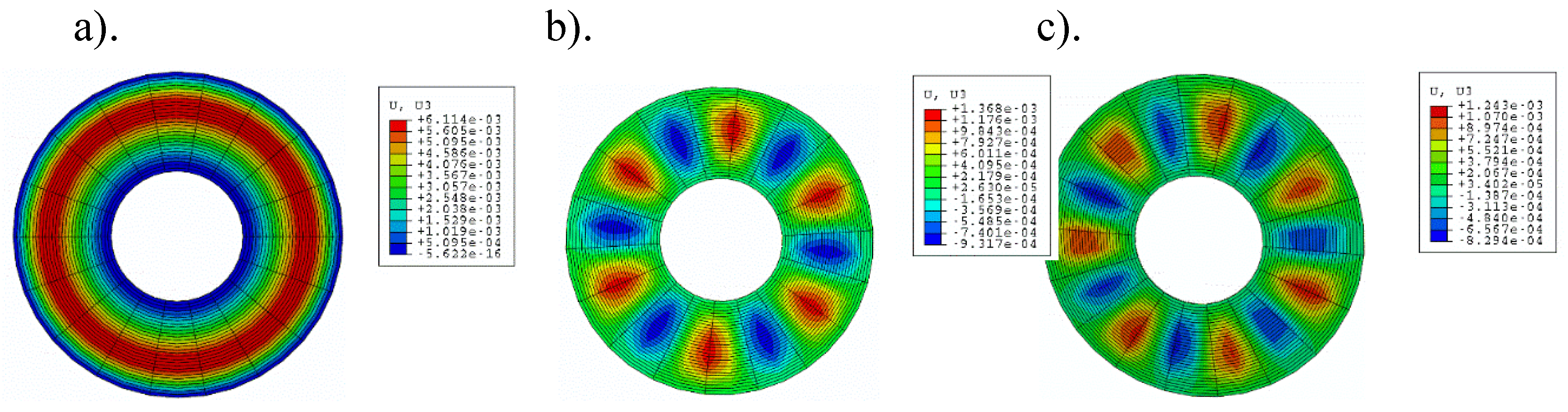
Exemplary forms of buckling—axisymmetric m = 0 and asymmetric with m = 6 and m = 7 circumferential waves for plates loaded on the outer edge—are shown in Figure 14.
Figure 11.
Distribution of the critical static load pcr versus mode number m for FDM and FEM plate models with homogeneous and St-Al facings with n = 0.2, 1, 5.
Figure 11.
Distribution of the critical static load pcr versus mode number m for FDM and FEM plate models with homogeneous and St-Al facings with n = 0.2, 1, 5.

Table 4.
Results for FDM and FEM plate models loaded on the outer edge.
| m | pcrdyn, MPa | |||||||||
| plate model | ||||||||||
| steel | aluminium | St-Al n=0.2 | St-Al n=1 | St-Al n=5 | ||||||
| FDM | FEM | FDM | FEM | FDM | FEM | FDM | FEM | FDM | FEM | |
| 0 | 37.5 | 37 | 29.5 | 21 | 29.5 | 27 | 33 | 29 | 38 | 33 |
| 4 | 23.5 | 24 | 18.5 | 19 | 18.5 | 20 | 21 | 21 | 23.5 | 22 |
| 5 | 21.5 | 22 | 17 | 17 | 17 | 18 | 19 | 19 | 21 | 20 |
| 6 | 20.5 | 21 | 16 | 16 | 16.5 | 17 | 18 | 19 | 20.5 | 20 |
| 7 | 21 | 22 | 15.5 | 16 | 15.5 | 18 | 18.5 | 19 | 20.5 | 20 |
Table 5.
Results for FDM and FEM plate models loaded on the inner edge.
| m | pcrdyn, MPa | |||||||||
| plate model | ||||||||||
| steel | aluminium | St-Al n=0.2 | St-Al n=1 | St-Al n=5 | ||||||
| FDM | FEM | FDM | FEM | FDM | FEM | FDM | FEM | FDM | FEM | |
| 0 | 102.5 | 100 | 67.5 | 65 | 77.5 | 90 | 92.5 | 100 | 100 | 100 |
Figure 12.
Time histories of deflections and velocity of deflections for plates with m = 0 loaded on the inner edge: a) aluminium plate model, b) St-Al plate model with n = 0.2, c) steel plate model.
Figure 12.
Time histories of deflections and velocity of deflections for plates with m = 0 loaded on the inner edge: a) aluminium plate model, b) St-Al plate model with n = 0.2, c) steel plate model.
Figure 13.
Time histories of deflections and velocity of deflections for plates with m = 6 loaded on the outer edge: a) St-Al plate model with n = 0.2, b) St-Al plate model with n = 1, c) St-Al plate model with n = 5, d) steel plate model.
Figure 13.
Time histories of deflections and velocity of deflections for plates with m = 6 loaded on the outer edge: a) St-Al plate model with n = 0.2, b) St-Al plate model with n = 1, c) St-Al plate model with n = 5, d) steel plate model.
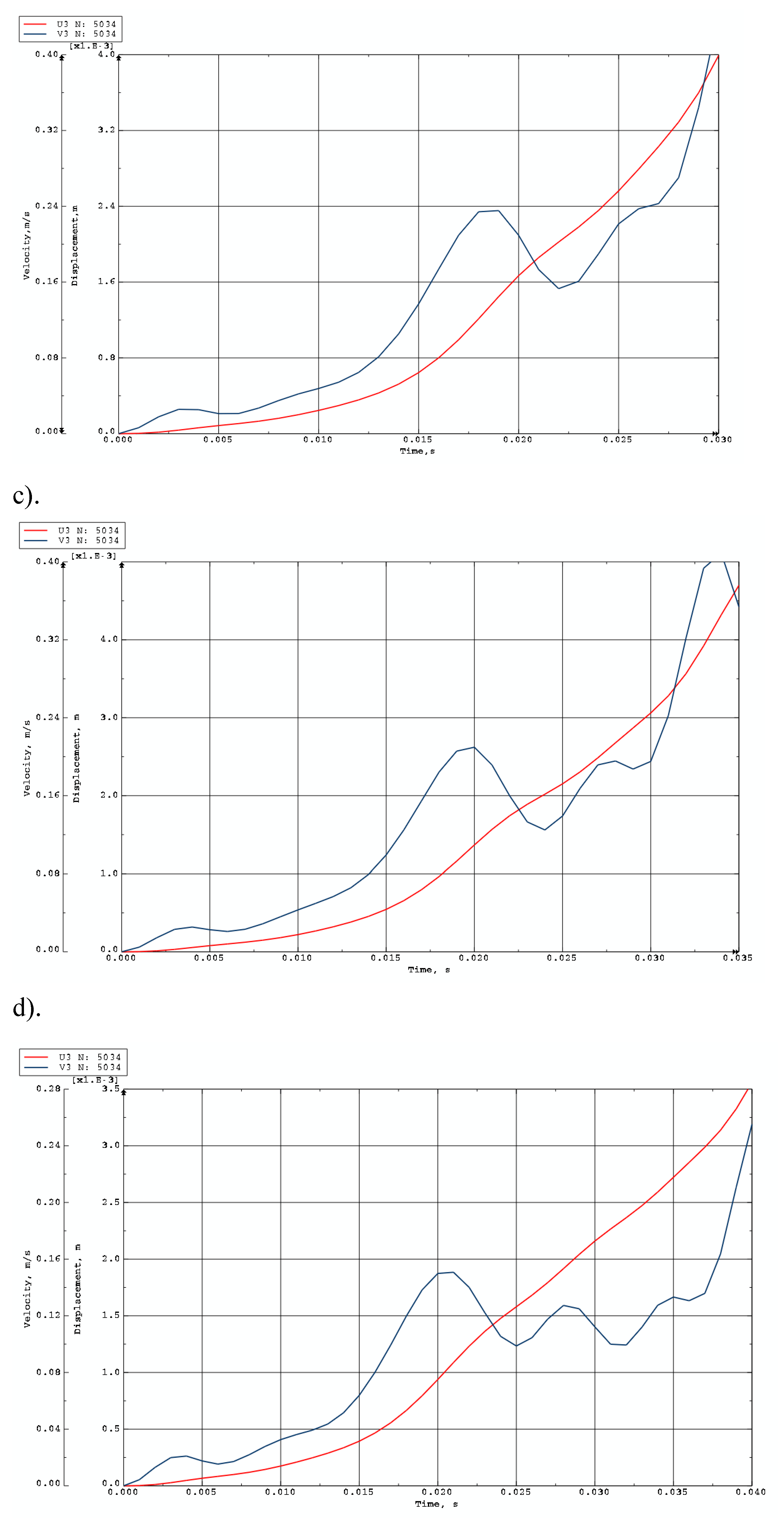
Figure 14.
Exemplary forms of plate buckling loaded on the outer edge: a) axisymmetric m = 0 St-Al model with n = 5, b) asymmetric m = 6 St-Al model with n = 5, c) asymmetric m = 7 St-Al model with n = 1.
Figure 14.
Exemplary forms of plate buckling loaded on the outer edge: a) axisymmetric m = 0 St-Al model with n = 5, b) asymmetric m = 6 St-Al model with n = 5, c) asymmetric m = 7 St-Al model with n = 1.
4.6. Analysis of Results for Two St-Al and Al-St FGM Plate Models
Results for the two plate models, St-Al and Al-St (see Figure 1), are presented in Figure 15, Figure 16, Figure 17, Figure 18 and Figure 19 and Table 6. The computational analyses for the two plate material models, St-Al and Al-St, focus on demonstrating the effect of FGM material arrangement in the plate facings on the critical static loads, pcr, and dynamic loads, pcrdyn. Differences in behavior are observed. Figure 15 shows the critical static load, pcr, for St-Al and Al-St FDM plate models loaded on the outer edge. The plate models exhibit opposite responses. The pcr values for the Al-St plate with n = 5, where aluminium is located near the inner plate edge, are the smallest, whereas for n = 0.2, the critical loads are close to those for a homogeneous steel plate. The FGM material distribution defined by Eqs. 2 and 3 with different values of n for the Al-St plate, shown in Figure 16, explains these changes. The softer aluminium material is concentrated near the inner edge for n = 5, resulting in generally smaller material parameters compared to n = 0.2. Results obtained using FEM do not show such clear differences for the FGM plate model with n = 0.2 (see Figure 17). For asymmetric modes, the pcr values for both St-Al and Al-St plate models converge. The opposite response trend for the two models is still observed. It can be concluded that, from a stability point of view, the lighter Al-St material distributed in the plate facings is more advantageous, providing higher critical static loads, pcr, for plates loaded on the outer edge.
The forms of the axisymmetric buckling of plates loaded on the inner and outer edges are shown in Figure 18. Differences in the critical deformations of the plate structure are visible between plates loaded on the inner and outer edges. This axisymmetric form is particularly important for plates loaded on the inner edge. This axisymmetric m = 0 mode corresponds to the plate model with the smallest critical load. The time history of dimensionless deflections presented in Figure 19 for the FDM Al-St plate model loaded dynamically on the inner edge confirms the results obtained for the Al-St plate model loaded statically. The smallest time to loss of plate stability, identifiable by the black dots, and the smallest value of the critical dynamic load pcrdyn occur for the plate model with n = 5. Larger stability parameters are observed for the plate with n = 0.2. Detailed values for the two material plate models, St-Al and Al-St, for both FDM and FEM computational models, are presented in Table 6. Plates are loaded statically and dynamically on the inner edge. For the FGM plate with n = 5, whose critical load values are close to those of a homogeneous steel or aluminium composite plate, the results depend on the material model (St-Al or Al-St). Detailed results show good agreement between the two computational models, FDM and FEM. Critical loads of the St-Al plate model are close to those of a homogeneous steel plate, while values obtained for the Al-St plate model are close to the critical loads for plates with aluminium facings. Considering the detailed values of pcr or pcrdyn calculated for the plate model with n = 5, the St-Al material plate model, for this specific material distribution, is more advantageous from a stability point of view for both inner and outer edge loads. The values of pcr and pcrdyn are close to those of a composite plate with steel facings. Exemplary time histories of deflections and deflection velocities for the two computational models, FDM and FEM, are presented in Figure 20. The Al-St plate model with n = 5 is loaded on the inner edge. For the FDM plate model, results are presented in dimensionless form, see Figure 20a. For example, dimensionless time t* is related to real time t, presented in Figure 20b, by the formula t* = tK7, where parameter K7 is equal to 20. The character of the presented curves for both FDM and FEM plate models is comparable. Characteristic overcritical vibrations, initiated by the increasing applied load, are observed.
Figure 15.
Distribution of the critical static load pcr versus mode number m for St-Al and Al-St FDM plate models, both homogeneous and with FGM facings, for power-law exponents n = 0.2, 1, 5.
Figure 15.
Distribution of the critical static load pcr versus mode number m for St-Al and Al-St FDM plate models, both homogeneous and with FGM facings, for power-law exponents n = 0.2, 1, 5.
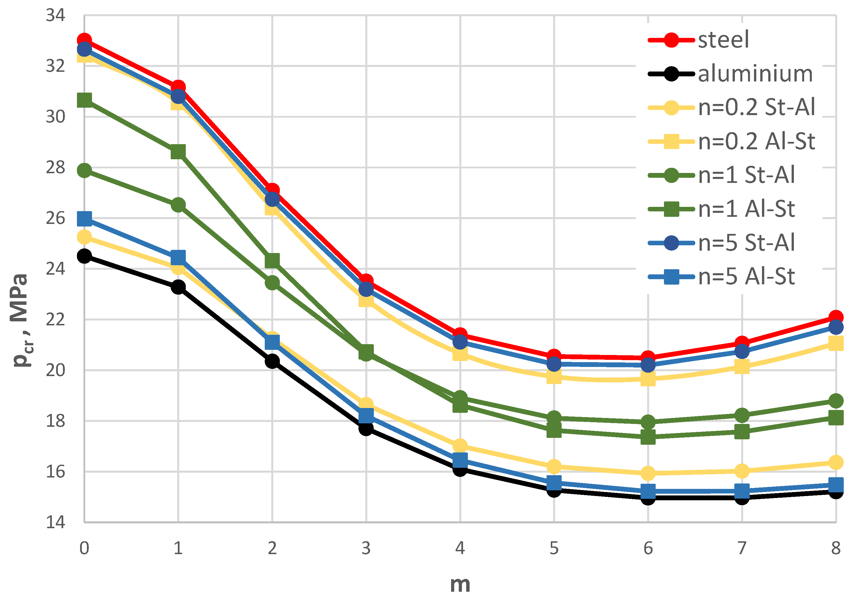
Figure 16.
Distribution of Young’s modulus Er of St-Al and Al-St FGM facings versus plate radius ρ.
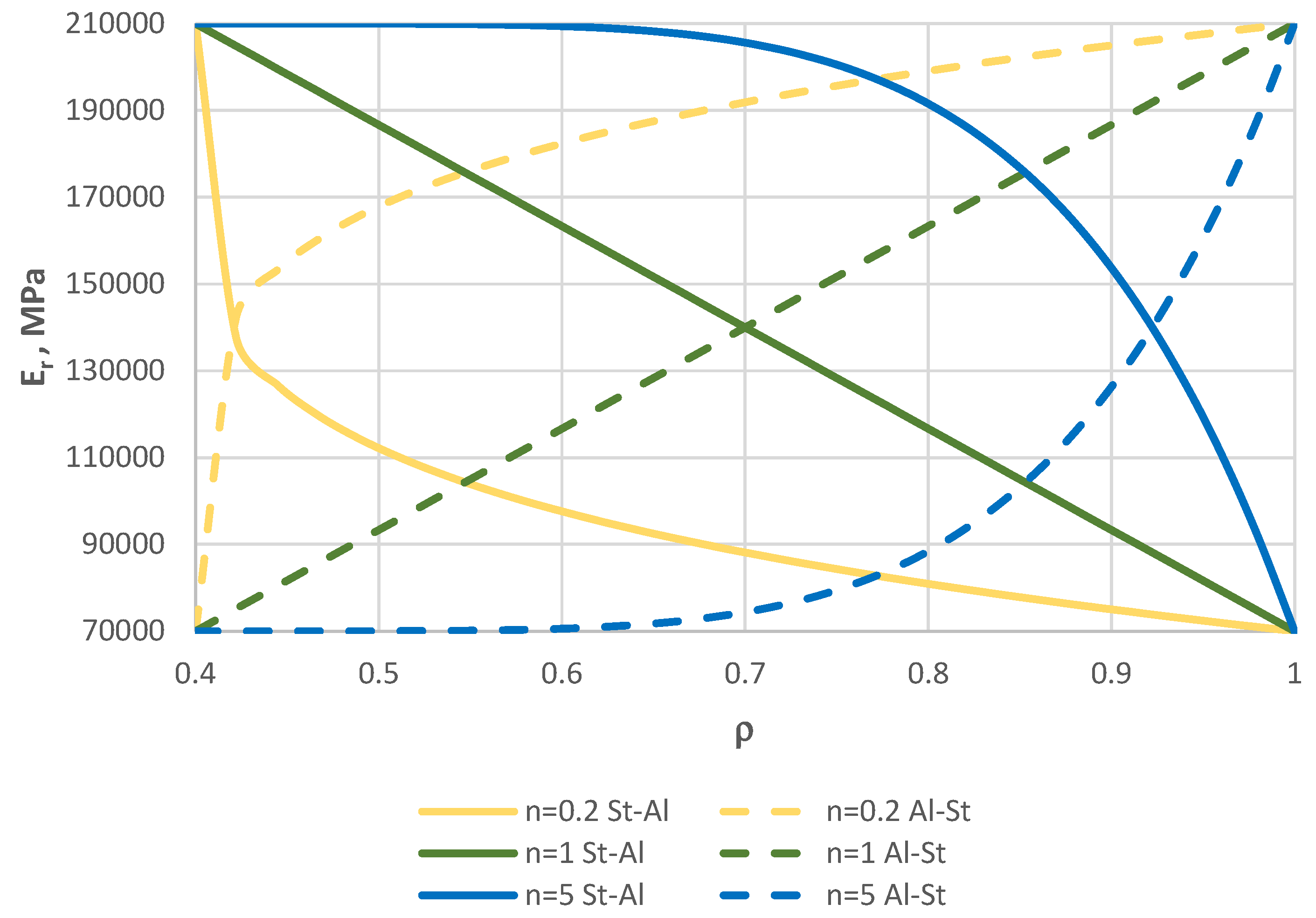
Figure 17.
Distribution of the critical static load pcr versus mode number m for homogeneous, St-Al, and Al-St FEM plate models, with power-law exponents n = 0.2, 1, 5.
Figure 17.
Distribution of the critical static load pcr versus mode number m for homogeneous, St-Al, and Al-St FEM plate models, with power-law exponents n = 0.2, 1, 5.
Figure 18.
Axisymmetric m = 0 buckling modes for the FEM plate model loaded on a) inner edge, b) outer edge.
Figure 18.
Axisymmetric m = 0 buckling modes for the FEM plate model loaded on a) inner edge, b) outer edge.
Table 6.
Critical static pcr and dynamic pcrdyn loads for St-Al and Al-St FDM and FEM plate models loaded on the inner edge.
Table 6.
Critical static pcr and dynamic pcrdyn loads for St-Al and Al-St FDM and FEM plate models loaded on the inner edge.
| m=0 | homogeneous plate model | FGM plate model with n=5 | ||||||
| steel | aluminium | St-Al | Al-St | |||||
| FDM | FEM | FDM | FEM | FDM | FEM | FDM | FEM | |
| pcr, MPa | 76.57 | 71.78 | 49.23 | 46.75 | 76.56 | 71.83 | 49.36 | 46.67 |
| pcrdyn, MPa | 102.5 | 100 | 67.5 | 65 | 100 | 95 | 67.5 | 60 |
Figure 19.
Time history of dimensionless deflections ζ1max versus power-law exponent n for FDM Al-St plate models loaded on the inner edge.
Figure 19.
Time history of dimensionless deflections ζ1max versus power-law exponent n for FDM Al-St plate models loaded on the inner edge.
Figure 20.
Dynamic results for the Al-St plate (m = 0) with n = 5 loaded on the inner edge: a) dimensionless deflections and velocities for the FDM plate model; b) deflections and velocities for the FEM plate model.
Figure 20.
Dynamic results for the Al-St plate (m = 0) with n = 5 loaded on the inner edge: a) dimensionless deflections and velocities for the FDM plate model; b) deflections and velocities for the FEM plate model.
5. Conclusions
This paper presents the dynamic responses of composite annular plates with facings made of FGM. Alternating changes in material properties create two types of plate models with facings of steel-aluminium or aluminium-steel. In these models, the material with steel or aluminium parameters adheres to the inner edge, while aluminium or steel adheres to the outer edge, respectively. Radial changes of the material parameters are determined by a power function, in which the power-law exponent n takes the values n = 0.2, 0.5, 1, 2, 5. Numerical calculations have been conducted for two models: one using the FDM and the other using the FEM.
The results of the numerical calculations are presented with consideration of the evaluation of the plate critical state parameters. The main observations concern the critical dynamic loads, which are complemented by the evaluation of the changes in values determined for the static state of the plate, namely the critical static loads. The discussion of the calculation results highlights the importance of the radial distribution of the facing material in relation to the type of plate edge loading: inner or outer. In the pursuit of building composite plate structures with greater resistance to buckling, attention is focused on cases of plates with higher critical parameter values. Specifically, these are the cases in which the values of pcrdyn or pcr approach their maximum values, which are associated with steel facings. The most appropriate model is the St-Al plate model with an exponent of n = 5 for the material power function under outer edge loading, or a plate with n = 0.2 under inner edge loading. The benefit of using FGM material with radially variable parameters is a significant reduction in plate weight with only a slight decrease in stability-related properties.
The computational models, built according to the assumptions and limitations of the applied approximation methods, were tested. The static and dynamic responses of both FDM and FEM plate models are consistent. Observed differences in critical load values mainly concern the plate with n = 0.2, whose facings are more flexible due to the increased contribution of aluminium parameters. The proposed analytical and numerical FDM solution procedure demonstrates techniques for modeling complex plate structures and enables rapid, effective calculations for variable plate parameters. From a practical point of view, the effectiveness of the proposed procedure is high.
It is possible to extend the analyses to cases of plates whose facing material functions have various forms. The presented numerical research should be complemented by experimental analyses. Additionally, considering a heterogeneous material for the plate core could significantly enrich the evaluation of the examined composite plates. This topic will be addressed in future work.
Funding
This research received no external funding.
Institutional Review Board Statement
Not applicable.
Informed Consent Statement
Not applicable.
Conflicts of Interest
The authors declare no conflict of interest.
List of Abbreviations and Main Parameters
| Abbreviations |
| FGM – functionally graded material |
| FDM – finite difference method FEM – finite element method |
| St-Al – plate material model with steel on the inner edge and aluminium on the outer edge |
| Al-St – plate material model with aluminium on the inner edge and steel on the outer edge |
| Main parameters |
| ri – plate inner radius ro – plate outer radius r – plate radius ρi – dimensionless inner plate radius |
| h’ – facing thickness |
| h2 – core thickness |
| ESt – Young’s modulus of steel |
| EAl – Young’s modulus of aluminium |
| μSt – mass density of steel |
| μAl – mass density of aluminium |
| n – FGM-facing material power-law exponent (see Eq. 2) |
| G2 – Kirchhoff’s modulus of polyurethane foam as core material |
| N – number of discretization points pcrdyn – critical dynamic load tcr – critical time t* – dimensionless time ζ1max – dimensionless additional deflection pcr – critical static load |
| m – plate buckling mode |
References
- Asemi, K.; Salehi, M.; Akhlaghi, M. Post-buckling analysis of FGM annular sector plates based on three dimensional elasticity graded finite elements. International Journal of Non-Linear Mechanics 2014, 67, 164–177. [Google Scholar] [CrossRef]
- Civalek, Ömer; Baltacıoglu, Ali Kemal. Free vibration analysis of laminated and FGM composite annular sector plates. Composites Part B 2019, 157, 182–194. [Google Scholar] [CrossRef]
- Yu-Hao Fan; Gui-Lin She. Low-velocity impact response of rotating 2DFGM annular plates with variable thickness. Communications in Nonlinear Science and Numerical Simulation 2026, volume 152, part D. [CrossRef]
- Golmakani, M.E.; Kadkhodayan, M. Large deflection analysis of circular and annular FGM plates under thermo-mechanical loadings with temperature-dependent properties. Composites: Part B 2011, 42, 614–625. [Google Scholar] [CrossRef]
- Pankaj Sharma; Rahul Singh. Investigation on modal behaviour of FGM annular plate under hygrothermal effect. IOP Conf. Series: Materials Science and Engineering 2019, 624, 0120. [Google Scholar] [CrossRef]
- Sumit Khare; Rahul Vishwakarma; Dilsukh Vasara and Rahul Kumar. Prediction of natural frequencies of functionally graded circular and annular plate via differential quadrature method (DQM). ASPS Conference Proceedings 1 2022, 121-128. [CrossRef]
- Pawlus, D. Three-Layered Annular Plate Made of Functionally Graded Material Under a Static Temperature Field. Materials 2024, 17, 5484. [Google Scholar] [CrossRef] [PubMed]
- Pawlus, D. Dynamic response of three-layered annular plates in time-dependent temperature field. International Journal of Structural Stability and Dynamics. 2020, vol. 20, no. 12. [CrossRef]
- Pawlus, D. Stability of three-layered annular plate in stationary temperature field. Thin-Walled Structures, 2019, 144.
- Faraz Kiarasi; Masoud Babaei; Kamran Asemi,; Rossana Dimitri and Francesco Tornabene. Free Vibration Analysis of Thick Annular Functionally Graded Plate Integrated with Piezo-Magneto-Electro-Elastic Layers in a Hygrothermal Environment. Appl. Sci. 2022, 12, 10682. [Google Scholar] [CrossRef]
- Shishesaz, M.; Zakipour, A.; Jafarzadeh, A. Magneto-Elastic Analysis of an Annular FGM Plate Based on Classical Plate Theory Using GDQ Method. Latin American Journal of Solids and Structures 2016, 13, 2736–2762. [Google Scholar] [CrossRef]
- Yas, M.H.; Jodaei, A.; Irandoust, S.; Nasiri Aghdam, M. Three-dimensional free vibration analysis of functionally graded piezoelectric annular plates on elastic foundations. Meccanica. 2012, 47, 1401–1423. [Google Scholar] [CrossRef]
- Dilsukh Vasara; Sumit Khare; Harish Kumar Sharma; Rahul Kumar. Free vibration analysis of functionally graded porous circular and annular plates using differential quadrature method. Forces in Mechanics 2022, 9, 100126. [Google Scholar] [CrossRef]
- Jinseok Kim; Enrique Nava and Semsi Rakici. Nonlinear Finite Element Model for Bending Analysis of Functionally-Graded Porous Circular/Annular Micro-Plates under Thermomechanical Loads Using Quasi-3D Reddy Third-Order Plate Theory. Materials 2023, 16, 3505. [Google Scholar] [CrossRef]
- Tomczyk, B.; Gołąbczak, M. Tolerance and asymptotic modelling of dynamic thermoelasticity problems for thin micro-periodic cylindrical shells. Meccanica. 2020, 55, 2391–2411. [Google Scholar] [CrossRef]
- Tomczyk, B.; Gołąbczak, M.; Litawska, A.; Gołąbczak, A. Mathematical modelling of thermoelasticity problems for thin periodic cylindrical shells. Continuum Mech. Thermodyn. 2022, 34, 367–385. [Google Scholar] [CrossRef]
- Tomczyk, B.; Bagdasaryan, V.; Gołąbczak, M.; Litawska, A. A new combined asymptotic tolerance model of thermoelasticity problems for thin biperiodic cylindrical shells. Compos. Struct. 2013, 309, 116708. [Google Scholar] [CrossRef]
- Ostrowski, P.; Jędrysiak, J. Dependence of temperature fluctuations on randomized material properties in two-component periodic laminate. Compos. Struct. 2021, 257, 113171. [Google Scholar] [CrossRef]
- Jędrysiak, J. On stability of thin periodic plates. Eur. J. Mech. A/Solids, 2000, 19, 487–502. [Google Scholar] [CrossRef]
- Jędrysiak, J. The tolerance averaging model of dynamic stability of thin plates with one directional periodic structure. Thin-Walled Struct. 2007, 45, 855–860. [Google Scholar] [CrossRef]
- Jędrysiak, J.; Kaźmierczak-Sobińska, M. Free Vibration Analysis of Thin Functionally Graded Plate Bands with Microstructure as a Function of Material Inhomogeneity Distribution and Boundary Conditions. Materials 2025, 18, 4629. [Google Scholar] [CrossRef]
- Chen, Y.R.; Chen, L.W.; Wang, C.C. Axisymmetric dynamic instability of rotating polar orthotropic sandwich annular plates with a constrained damping layer. Composite Structures 2006, 73, 290–302. [Google Scholar] [CrossRef]
- Wang, H.J.; Chen, L.W. Axisymmetric dynamic stability of rotating sandwich circular plates. Journal Vibration and Acoustics 2004, 126, 407–415. [Google Scholar] [CrossRef]
- Pawlus, D. Dynamic stability of three-layered annular plates with wavy forms of buckling. Acta Mech. 2011, 216, 123–138. [Google Scholar] [CrossRef]
- Pawlus, D. Solution to the problem of axisymmetric and asymmetric dynamic instability of three-layered annular plates. Thin-Walled Structures 2011, 49(5), 660-668. [CrossRef]
- Garg, A.; Chalak, H.D.; Li, L.; Belarbi, M. O.; Sahoo, R.; Mukhopadhyay, T. Vibration and Buckling Analyses of Sandwich Plates Containing Functionally Graded Metal Foam Core. Acta Mechanica Solida Sinica. published online: 15 January 2022. [CrossRef]
- Wolmir, C. Nonlinear dynamic of plates and shells, Moskwa, Science, 1972 (in Russian).
- Wolmir, C. Stability of deformed system, Moskwa, Science, 1967 (in Russian).
- 26 Pawlus, D. Dynamic response of three-layered annular plate with imperfections. Studia Geotechnica et Mechanica 2014, vol. XXXVI, no. 4. [CrossRef]
- Pawlus, D. Static stability of composite annular plates with auxetic properties. Materials 2022, 15, 3579. [Google Scholar] [CrossRef] [PubMed]
- Wojciech, S. Numerical determination of critical temperatures for annular plates. Archive of Mechanical Engineering, 1980, XXVII, 3, 267-281 (in Polish).
- Trombski, M.; Wojciech, S. The cylindrically orthotropic annular plate subjected to time-dependent pressure acting in its plane. The Archive of Mechanical Engineering 1981, XXVIII, 2, 161-181 ( in Polish).
Figure 1.
Plate material models: a) St-Al, b) Al-St .
Figure 2.
Plate scheme compressed on the outer edge (1, 3 – thin facings with thickness h’, 2 – foam core with thickness h2).
Figure 2.
Plate scheme compressed on the outer edge (1, 3 – thin facings with thickness h’, 2 – foam core with thickness h2).
Figure 3.
Distribution of the critical dynamic load pcrdyn versus mode number m for the St-Al plate model loaded on the outer edge with various values of n and number N of discrete points.
Figure 3.
Distribution of the critical dynamic load pcrdyn versus mode number m for the St-Al plate model loaded on the outer edge with various values of n and number N of discrete points.
Figure 4.
Distribution of the critical static load pcr versus mode number m for St-Al, steel, and aluminium plate models.
Figure 4.
Distribution of the critical static load pcr versus mode number m for St-Al, steel, and aluminium plate models.
Figure 5.
Distribution of the critical dynamic load pcrdyn versus mode number m for St-Al, steel, and aluminium plate models.
Figure 5.
Distribution of the critical dynamic load pcrdyn versus mode number m for St-Al, steel, and aluminium plate models.
Figure 6.
Time history of dimensionless deflections ζ1max depending on St-Al plate mode m for n = 0.2.
Figure 6.
Time history of dimensionless deflections ζ1max depending on St-Al plate mode m for n = 0.2.
Figure 7.
Time history of dimensionless deflections ζ1max depending on St-Al plate mode m for n = 1.
Figure 7.
Time history of dimensionless deflections ζ1max depending on St-Al plate mode m for n = 1.
Figure 8.
Time history of dimensionless deflections ζ1max depending on St-Al plate mode m for n = 5.
Figure 8.
Time history of dimensionless deflections ζ1max depending on St-Al plate mode m for n = 5.
Figure 9.
Time history of dimensionless deflections ζ1max depending on steel, aluminium, and St-Al plate models for various power-law exponents n and plate mode m = 0.
Figure 9.
Time history of dimensionless deflections ζ1max depending on steel, aluminium, and St-Al plate models for various power-law exponents n and plate mode m = 0.
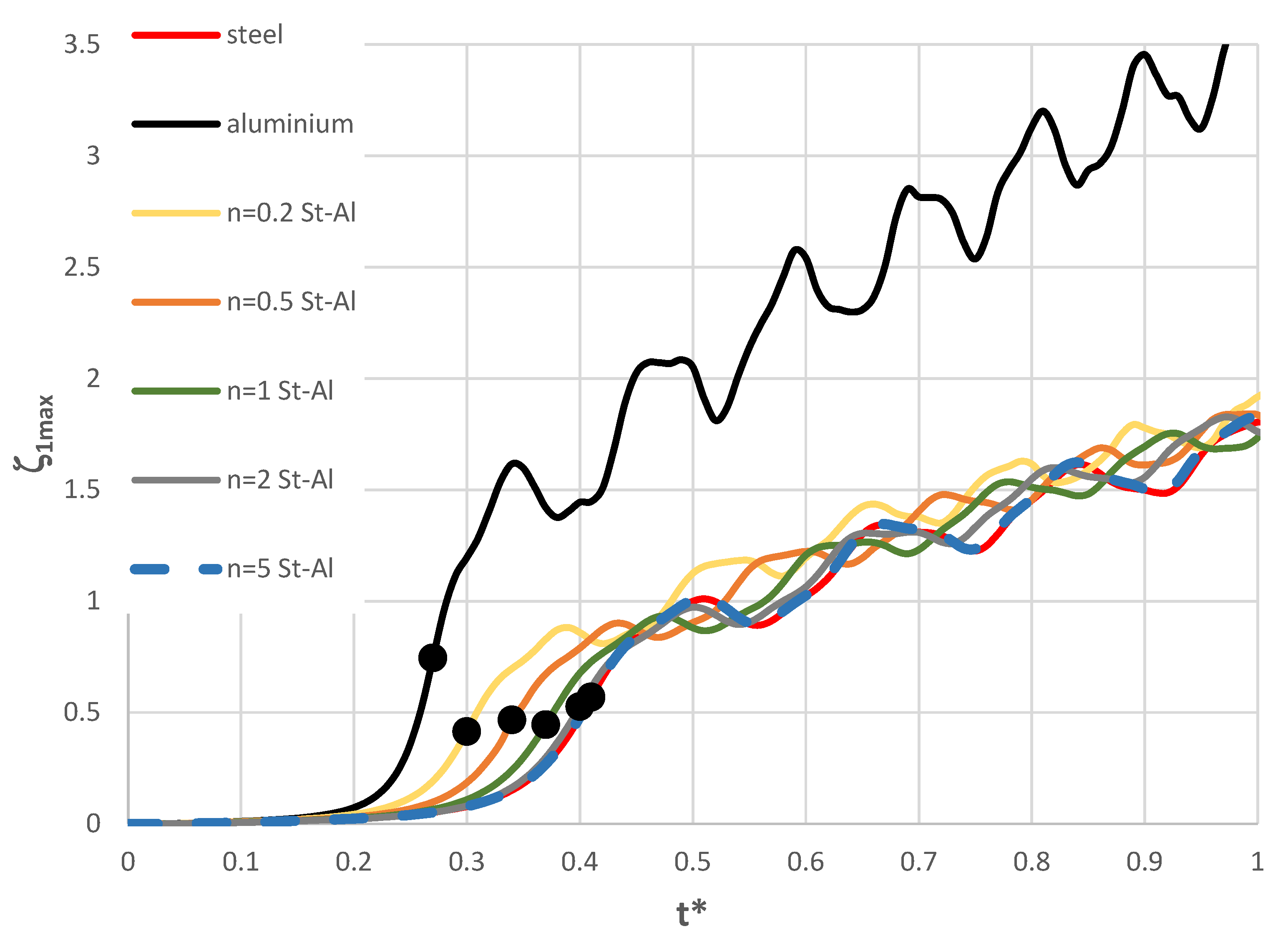
Figure 10.
Time history of dimensionless deflections ζ1max depending on steel, aluminium, and St-Al plate models for power-law exponent n = 1 and modes m = 0, 1, 2.
Figure 10.
Time history of dimensionless deflections ζ1max depending on steel, aluminium, and St-Al plate models for power-law exponent n = 1 and modes m = 0, 1, 2.
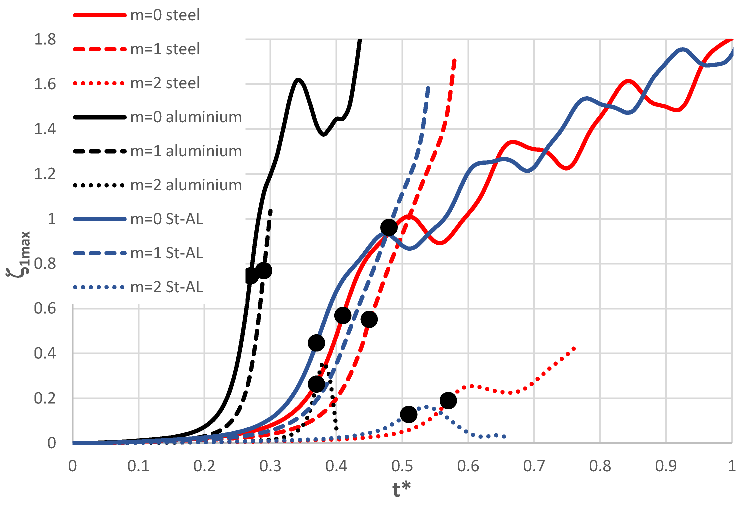
Table 1.
Geometrical and material plate parameters.
| Description | Parameter | Value |
|---|---|---|
| Geometrical parameters | ||
| plate inner radius | ri | 0.2 m |
| plate outer radius | ro | 0.5 m |
| facing thickness | h’ | 1 mm |
| core thickness | h2 | 5 mm |
| Material parameters | ||
| Young’s modulus of steel | Est | 210 GPa |
| Poisson’s ratio of steel | νst | 0.3 |
| mass density of steel | µst | 7850 kg/m3 |
| Young’s modulus of aluminium | Eal | 70 GPa |
| Poisson’s ratio of aluminium | νal | 0.33 |
| mass density of aluminium | µal | 2700 kg/m3 |
| Kirchhoff’s modulus of polyurethan foam of core material | Gc | 5 MPa |
| mass density of polyurethan foam of core material | µc | 64 kg/m3 |
| power-law exponent of the eq. (2) | n | 0.2, 0.5, 1, 2, 5 |
| Load parameters | ||
| rate of dynamic loading growth | s | 1000 MPa/s for plate loaded on the outer edge |
| 5000 MPa/s for plate loaded on the inner edge | ||
Table 2.
Detailed values of the critical dynamic loads pcrdyn versus mode number m for the St-Al plate model loaded on the outer edge for different values of n and number N of discrete points.
Table 2.
Detailed values of the critical dynamic loads pcrdyn versus mode number m for the St-Al plate model loaded on the outer edge for different values of n and number N of discrete points.
| m | pcrdyn , MPa | |||||
| St-Al model n=1 | St-Al model n=5 | |||||
| N=14 | N=20 | N=26 | N=14 | N=20 | N=26 | |
| 0 | 32.5 | 32 | 33 | 37.5 | 37.5 | 38 |
| 1 | 34 | 34 | 34 | 40 | 40 | 40 |
| 2 | 30.5 | 30.5 | 30.5 | 36 | 36 | 35 |
| 3 | 24.5 | 24.5 | 24.5 | 26.5 | 27 | 27,5 |
| 4 | 21 | 21 | 21 | 23 | 23 | 23.5 |
| 5 | 19 | 19 | 19 | 21 | 21 | 21 |
| 6 | 18.5 | 18.5 | 18 | 20 | 20 | 20.5 |
| 7 | 18 | 18 | 18.5 | 20.5 | 20.5 | 20.5 |
| 8 | 20.5 | 20.5 | 20 | 23 | 23 | 23 |
Table 3.
Critical dynamic pcrdyn and static pcr loads for the FDM plate model
| m | FDM plate model | |||||||||
| steel | aluminium | St-Al n=0.2 | St-Al n=1 | St-Al n=5 | ||||||
|
pcrdyn, MPa |
pcr, MPa | pcrdyn, MPa | pcr, MPa | pcrdyn, MPa | pcr, MPa | pcrdyn, MPa | pcr, MPa | pcrdyn, MPa | pcr, MPa | |
| 0 | 37.5 | 33.01 | 29.5 | 24.5 | 29.5 | 25.25 | 33 | 27.88 | 38 | 32.66 |
| 4 | 23.5 | 21.39 | 18.5 | 16.09 | 18.5 | 17.01 | 21 | 18.91 | 23.5 | 21.11 |
| 5 | 21.5 | 20.54 | 17 | 15.27 | 17 | 16.20 | 19 | 18.11 | 21 | 20.24 |
| 6 | 20.5 | 20.48 | 16 | 14.96 | 16.5 | 15.93 | 18 | 17.95 | 20.5 | 20.20 |
| 7 | 21 | 21.06 | 15.5 | 14.97 | 15.5 | 16.02 | 18.5 | 18.22 | 20.5 | 20.74 |
Disclaimer/Publisher’s Note: The statements, opinions and data contained in all publications are solely those of the individual author(s) and contributor(s) and not of MDPI and/or the editor(s). MDPI and/or the editor(s) disclaim responsibility for any injury to people or property resulting from any ideas, methods, instructions or products referred to in the content. |
© 2025 by the authors. Licensee MDPI, Basel, Switzerland. This article is an open access article distributed under the terms and conditions of the Creative Commons Attribution (CC BY) license (http://creativecommons.org/licenses/by/4.0/).
Copyright: This open access article is published under a Creative Commons CC BY 4.0 license, which permit the free download, distribution, and reuse, provided that the author and preprint are cited in any reuse.


