1. Background Theory
To ensure a solid theoretical foundation for subsequent derivations and avoid controversy, the basic theories relied upon in this study are listed as follows:
According to phase transition thermodynamics, after an object undergoes a complete phase transition cycle, the system state is restored, and no net energy is consumed, conforming to the law of energy conservation. The Curie phase transition originates from the reduction of quantum condensation energy levels and, similar to other phase transitions, also follows energy conservation.
According to the thermodynamics of magnetic media, for a magnetic medium in a magnetic field H with magnetization intensity M, if the induced magnetic field it excites is not considered, the magnetization work done by the magnetic field on the medium is:
[
1,
2,
3]
According to classical electrodynamics, the static magnetic field of a permanent magnet does mechanical work on an approaching ferromagnet: , where F is the magnetic force exerted by the permanent magnet on the ferromagnet, and L is the displacement of the ferromagnet in the magnetic field.
According to Ampère’s circuital law, the curl of the static magnetic field in a region without conduction current is zero, , belonging to a conservative field, satisfying . The magnetic field of a permanent magnet falls into this category of conservative fields.
According to the first law of thermodynamics , the energy of an isolated system can only undergo formal transformation or transfer, with the total amount conserved, and there is no time-lag effect in energy conservation.
The ideal gas equation of state, , shows that compressing or expanding a quantitative gas in an adiabatic box can achieve temperature changes inside the box. When the system returns to its original state, the temperature also restores, and the net work done by the external world on the system during this process is zero.
Advance Declaration Translation: This paper focuses on theoretical analysis; therefore, the following simplified assumptions are made: magnetic hysteresis losses and other thermal dissipations in the model objects are not considered; the strength of the permanent magnet’s magnetic field is assumed not to decay when doing work on the ferromagnet; qualitative analysis assumes complete shielding of the magnetic field in the ferromagnetic state; displacement of objects in a force-free state consumes no energy; thermodynamic volume work pΔV caused by volume changes due to temperature or magnetic field variations (such as magnetostriction) is not considered, as such work is regarded as “virtual work” that does not act on external objects in this model, and it has no net effect on the system after one cycle due to volume restoration.
2. Problem Description and Simulation Model
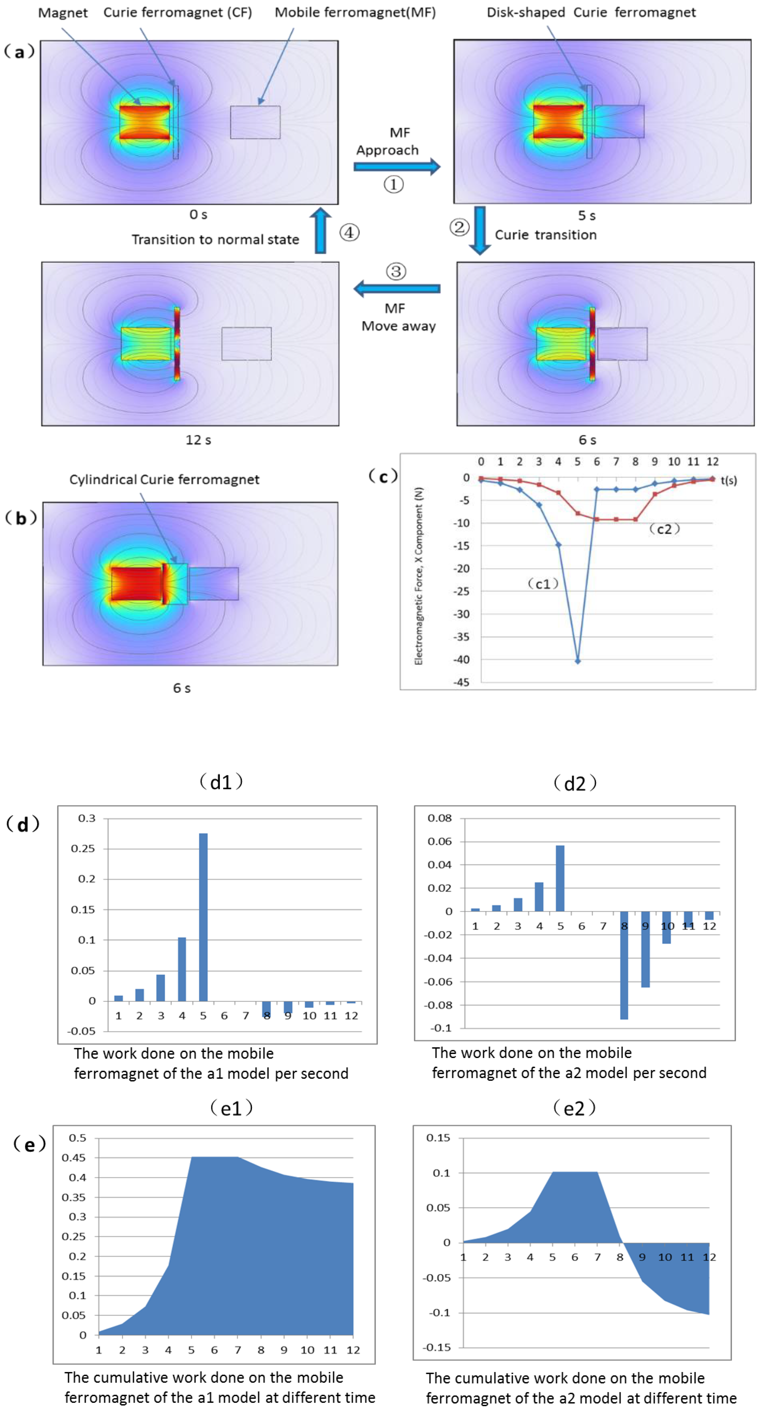
When using COMSOL to simulate the dynamic effects of the Curie phase transition on magnetic field distribution, we constructed a model simulating dynamic Curie phase transition shielding of the magnetic field and its effect on objects subjected to magnetic forces.As shown in
Figure 1a, the model consists of a fixed cylindrical permanent magnet on the left, used to establish a static magnetic field; a fixed disc-shaped Curie ferromagnet( hereinafter referred to as CF) in the middle; and a cylindrical mobile ferromagnet( hereinafter referred to as MF) on the right that can move left and right. The dynamic operation sequence of the model is as follows:
- 1)
Initial state: The MF is far away from the CF and the permanent magnet, while the CF is in the paramagnetic state (Curie state).
- 2)
Step ① (0-5 seconds): The MF approaches the CF.
- 3)
Step ② (the MF stops at 5 seconds, within 5-6 seconds): The CF undergoes a phase transition from the paramagnetic state to the ferromagnetic state, simultaneously shielding the magnetic field.
- 4)
Step ③ (6-11 seconds): The MF moves away from the CF.
- 5)
Step ④: The CF returns to the paramagnetic state, and the system returns to the initial state.
Figure 1b displays the simulation cloud diagram after changing the CF in the
Figure 1a model from a disc shape to a cylindrical shape, with all other parameters and action sequences unchanged.
Figure 1c respectively shows the curves of the magnetic force experienced by the MF over time (displacement) within one complete cycle in the two models of
Figure 1a and
Figure 1b. A negative force indicates that the force direction is opposite to the simulation coordinate system direction. Curve c1 in
Figure 1c corresponds to the
Figure 1a model. It can be seen that from 0-5 seconds, the force on the MF gradually increases; at 6 seconds, due to the CF phase transition shielding the magnetic field, the force sharply decreases to nearly zero, and subsequently remains very small during the moving away process. The time integral of the magnetic force is the work it does on displacement. Clearly, the integral of this force over a closed path is not zero. Comparing curves c1 and c2 in
Figure 1c, it is evident that the force curves on the MF in the two models are entirely different, especially after the phase transition is completed at 6 seconds, where the trends of force change are completely opposite. This indicates that merely changing the geometric shape of the CF (from disc-shaped to cylindrical) causes significant changes in the electromagnetic force experienced by the MF.
Figure 1d and e further show that the MF in the
Figure 1a model obtains net positive work (
W > 0), while the MF in the
Figure 1b model obtains net negative work (
W < 0). According to the law of energy conservation, for the entire system, the CF in the
Figure 1a model needs to expend energy, while in the
Figure 1b model it needs to absorb energy. However, for two Curie phase transition models with identical action sequences, the electromagnetic thermodynamic influence of the MF on the CF should be the same. The fact that merely a change in the shape (thickness) of the CF leads to one producing a positive work effect and the other a negative work effect is quite peculiar. The permanent magnet is the direct source of mechanical work for the MF. However, the static magnetic field of the permanent magnet is originally a conservative field; without the intervention of the intermediate CF’s phase transition, the integral of the magnetic force on the MF over a closed path must be zero, with net work zero. It is precisely the phase transition of the CF that changes the spatiotemporal distribution of the magnetic field, causing the permanent magnet to do net work on the MF without changing its own internal energy. In this simplified system containing only three objects, the source of the net work can only be explored starting from the CF, which requires further analysis of whether there is net energy exchange between the CF and the MF.
3. Analysis of Energy Exchange Between MF and CF
To clarify the energy exchange mechanism between the MF and the CF, it is necessary to focus on analyzing the instantaneous effects of their electromagnetic interaction during the phase transition process. Below, thermodynamic formulas are used for detailed analysis.
For convenience of expression, define in the
Figure 1a model: Object 1 as the permanent magnet, Object 2 as the CF, Object 3 as the MF. Formula parameters use corresponding subscripts, for example,
H1 denotes the magnetic field produced by permanent magnet 1,
M2 denotes the magnetic moment of CF 2 under the action of
H1,
M2 is the magnetic moment of the CF with respect to
H1 , and
denotes the work done by the permanent magnet’s magnetic force on the MF.
Analysis shows that although transient electromagnetic interactions exist during the phase transition process, after one complete cycle, the cumulative magnetization work between the two is zero. This indicates that the CF does not provide or absorb net energy for the MF.
Analysis of the
Figure 1a model: From 0-5 seconds, the CF is in the paramagnetic state, responding weakly to the magnetic field. During the 5-6 second period, it undergoes a phase transition from the paramagnetic state to the ferromagnetic state. In this stage, the CF partially shields the external magnetic field, and the unshielded part causes the MF to produce an induced magnetic field B. This induced magnetic field B exerts transient magnetization work on the CF:
(here, H should be equivalently represented by the field induced by B). From 6-12 seconds, the CF becomes ferromagnetic and completely shields the magnetic field, and the induced magnetic field
B of the MF disappears accordingly. Therefore, the cumulative magnetization work of the MF on the CF is zero:
. If the permanent magnet’s magnetic field has already saturated the magnetization of the CF, then the induced magnetic field B of the MF cannot exert further influence, more directly proving no net work exchange between the two.
Analysis of the Figure 1b model: The behavior from 0-5 seconds is the same as in
Figure 1a. After 5 seconds, due to the changed shape of the CF, its function shifts to conducting and concentrating the magnetic field, causing the magnetic field where the MF is located to continuously enhance after the phase transition begins. The induced magnetic field B produced by the MF does work on the CF, but during its moving away process, the effect is offset in the form of negative work. Ultimately, the cumulative magnetization work between the two is also zero.
It is thus concluded that in both models, there is no net energy exchange between the CF and the MF. However, the MF obtains net mechanical work from the permanent magnet: . This superficially appears to violate the law of energy conservation. The reason may lie in the Curie phase transition altering the spatiotemporal distribution of the magnetic field, thereby affecting the electromagnetic force on the MF and its net mechanical work.
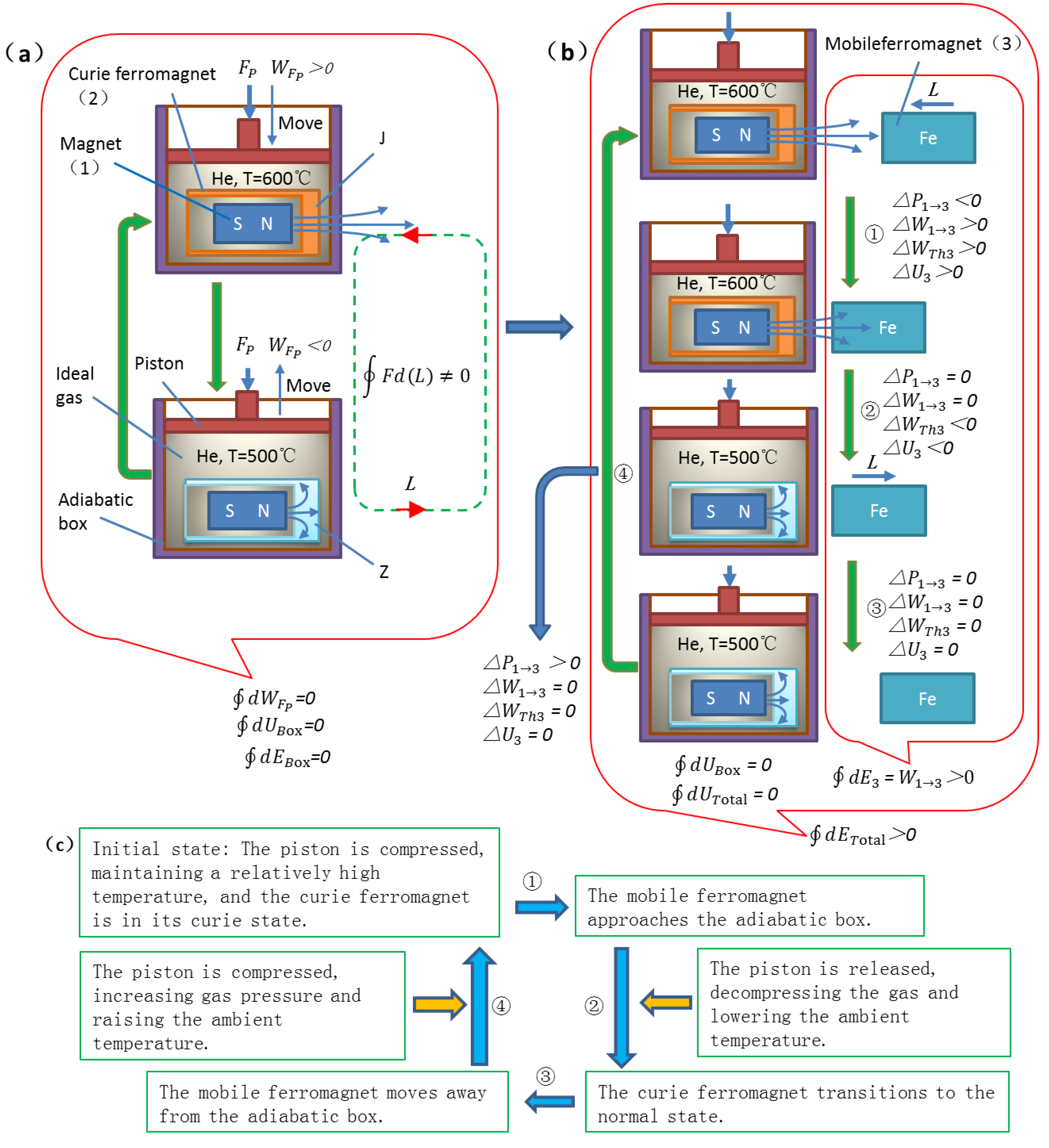
Given that there are still views suspecting that repeated phase transitions of the object itself consume energy, to avoid controversy, the adiabatic box system shown in
Figure 2a is used for further analysis below.
Therefore, consider the adiabatic box system shown in
Figure 2a (containing the CF and permanent magnet, without the MF). The external world controls the temperature inside the box by compressing or releasing the gas via a piston, thereby inducing the Curie phase transition. Let the internal energy of the adiabatic box system be
, then after the system experiences one cycle, the change in internal energy
, conforming to energy conservation. In the complete model of
Figure 2b (including the MF), the Curie phase transition system is placed inside this adiabatic box. After the model runs one cycle, although there is no net energy exchange between the CF and the MF, the MF obtains non-zero net mechanical work, which contradicts the law of energy conservation.
4. Reason for MF Obtaining Net Work: Temporally Sequential Non-Conservative Field
For the Curie phase transition system in
Figure 2a, the CF intermittently shields the permanent magnet’s magnetic field during one phase transition cycle, objectively changing the spatial distribution of the static magnetic field on the right side of the system in a time-sequential manner, thereby transforming the conservative field in this region into
a temporally sequential non-conservative field. In this temporally sequential non-conservative field, moving according to a specific time sequence, the closed path integral of the magnetic force exerted by the permanent magnet is no longer zero:
. The key point is that the Curie phase transition system in
Figure 2a itself is energy-conserving, and the phase transition process does not consume any net energy. This means that
forming this temporally sequential non-conservative field itself requires no energy consumption. As mentioned earlier, the magnetic field of the permanent magnet is originally a conservative field, and the work on a closed path for the MF is zero. It is precisely the phase transition of the CF that changes the magnetic field distribution in time sequence, causing the MF to obtain non-zero mechanical work when moving according to the corresponding time sequence. As shown in
Figure 2b, introducing the MF on the right and making it move according to a specific time sequence could completely cause it to obtain net positive work; if it is moved in the reverse direction, it may obtain net negative work. Both cases contradict the law of energy conservation.
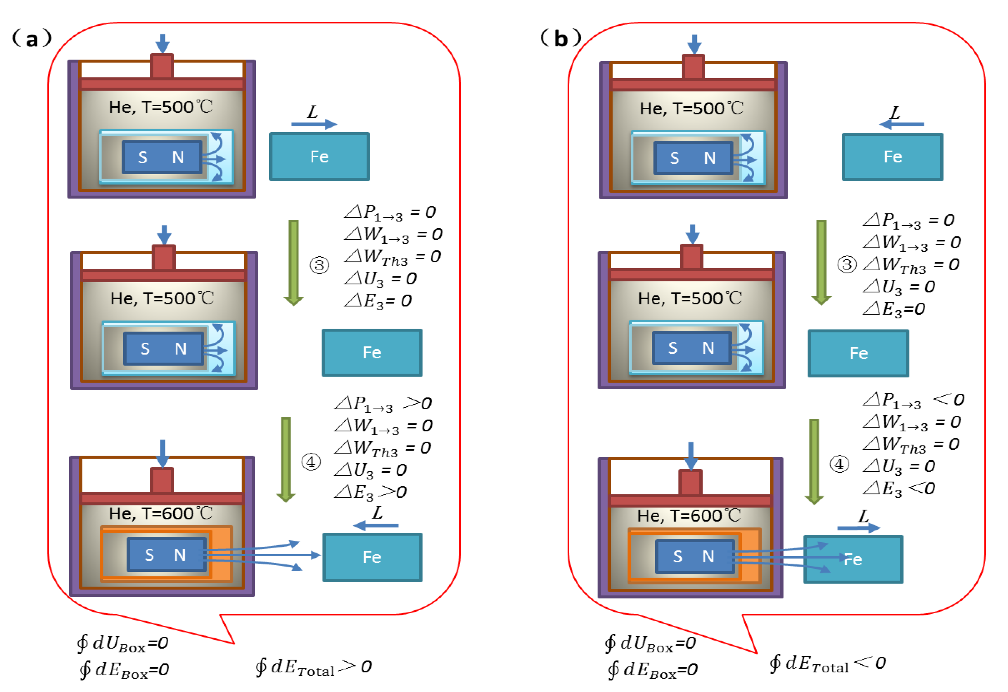
For ease of analysis, Steps ③ and ④ are extracted from the
Figure 2b model, as shown in
Figure 3a.
Step ③: The MF moves away from the CF. At this time, due to the shielding of the permanent magnet’s magnetic field, the MF is not subjected to magnetic attraction, so the moving away process requires no external work (if the magnetic field were not shielded, moving away would require external work to overcome magnetic attraction). However, during this process, the “potential energy” of the MF relative to the (shielded) permanent magnet’s magnetic field continuously increases. In this step, the unmagnetized MF has no effect on the Curie phase transition system inside the adiabatic box. In this step alone, the phenomenon of the MF’s potential energy increasing alone without a corresponding decrease in other energy has already appeared, contradicting the law of energy conservation.
Step ④: The external world does work on the adiabatic box through the piston, driving the Curie phase transition system to undergo phase transition. According to phase transition thermodynamics and energy conservation, the external work is converted into the internal energy of the system inside the box, and the phase transition itself does not consume net energy, so this step still conserves the energy of the adiabatic box system. The CF phase transition restores to the paramagnetic state, the magnetic field shielding is lifted, and the “potential energy” of the MF transforms into real potential energy. According to the first law of thermodynamics, the energy of an isolated system should be conserved at any moment, but in this model, the separate increase in the MF’s potential energy contradicts the law.
5. Key Steps of Proof by Contradiction for Energy Non-Conservation
Given that the above analysis is entirely based on basic physical theories such as the law of energy conservation, yet the derivation results contradict the law itself, this problem has been transformed into a mathematical logic problem. Therefore, proof by contradiction is used for argumentation below.
Consider Steps ③ and ④ in
Figure 3a. The MF requires no external work when moving away due to the absence of magnetic force, and subsequently, the restoration of the magnetic field causes it to gain potential energy. This increase in potential energy is equivalent to obtaining net mechanical work. Assuming the system still conserves energy, there must be a decrease in some other part of the energy. The most likely is a decrease in the internal energy of the adiabatic box system. However, according to physical common sense, the MF, located outside the adiabatic box and unmagnetized, cannot in any way cause a decrease in the internal energy of the adiabatic box system regardless of its motion. This contradicts the assumption, so the original assumption (system energy conservation) does not hold. Similarly, for the case of the MF moving in reverse (
Figure 3b), it does not receive positive work from the magnetic field when approaching, yet ultimately loses potential energy (obtains negative work), while also unable to increase the internal energy of the adiabatic box, also leading to non-conservation of system energy.
Therefore, regardless of the direction of motion of the MF, its only obtaining net mechanical work (positive or negative) without energy compensation from the system contradicts the law of energy conservation.
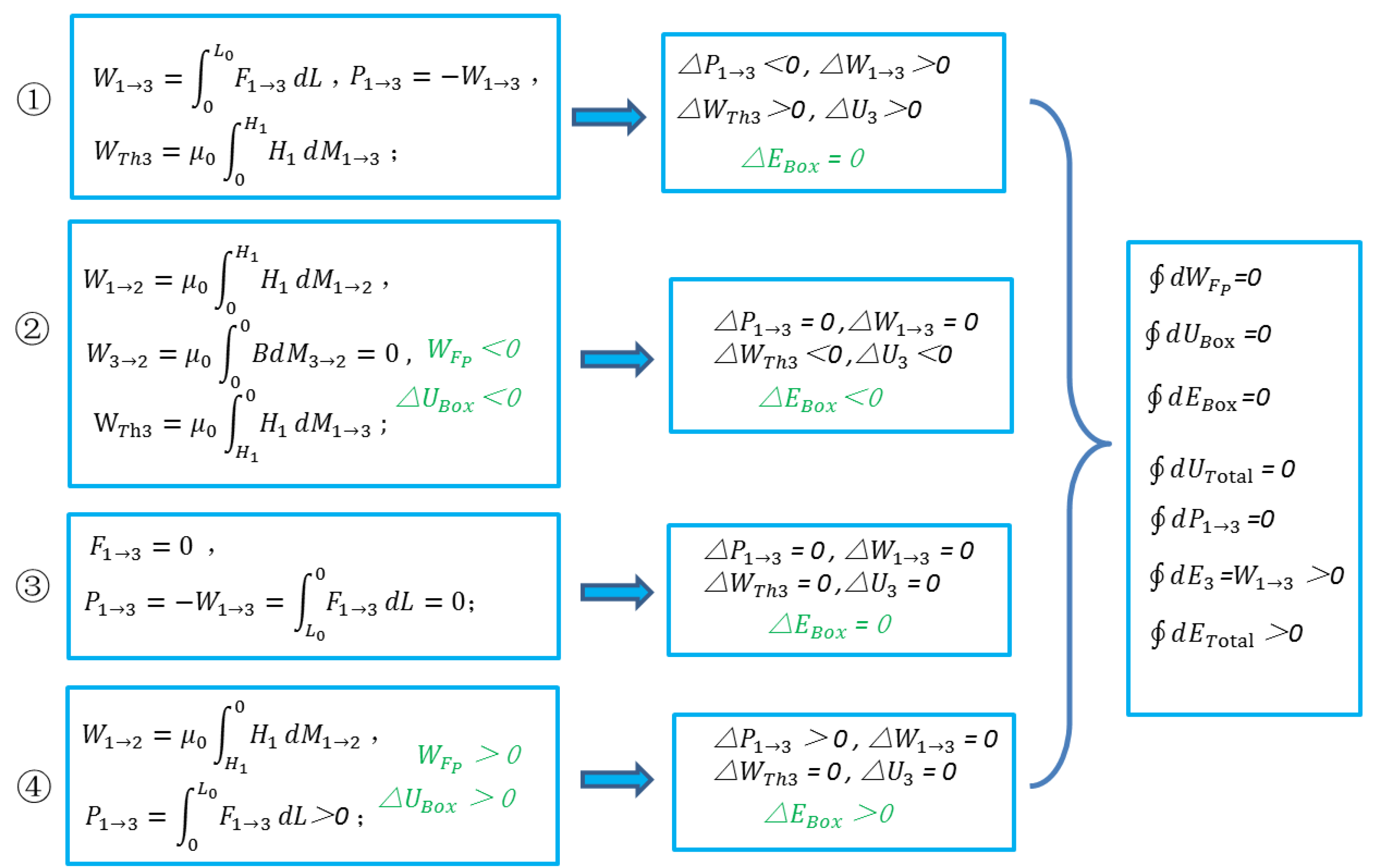
6. Summary of Overall Model Energy Analysis
A unified analysis of the work of interaction between all objects in the model, especially the work exchange between the MF and the system inside the adiabatic box (permanent magnet, CF), is conducted (the analysis process is based on the thermodynamics of magnetic media, similar to the previous text, omitted here), and the conclusions are summarized in
Figure 4.
Comprehensive analysis shows that the cumulative magnetization work of the MF on the CF is zero, and there is no net energy input or output to the entire adiabatic box system over one cycle. Considering the adiabatic box as an isolated system, its internal phase transition process conserves energy. However, the net increase in the potential energy of the MF itself directly leads to the total energy of the entire model no longer being conserved.
Specifically, the adiabatic box system in
Figure 2b is the same as in
Figure 2a, energy conserved:
. But after the entire Curie phase transition model (including the MF) completes one cycle, the MF obtains the net work done by the permanent magnet’s magnetic force:
, causing the total energy of the model not to be conserved:
.
7. Conclusion and Research Outlook
This paper, through simulation research on ferromagnetic shielding phenomena, discovered that a Curie phase transition model during one phase transition cycle may cause a MF to obtain net work, thereby causing the entire model to exhibit characteristics of energy non-conservation. After analyzing the interaction work between objects within the model based on fundamental theories such as Curie phase transition theory, thermodynamics of magnetic media, and classical electrodynamics, it is concluded that an adiabatic Curie phase transition system, without consuming net energy for phase transition, can form a temporally sequential non-conservative field in a specific region. This field enables the MF to obtain net mechanical work, while there is no net energy exchange between the MF and the CF, ultimately leading to the total energy of the entire model no longer being conserved, contradicting the law of energy conservation. This paper aims to reveal this theoretical contradiction and call for in-depth exploration by the academic community. This issue holds significant importance for the understanding of the nature of “fields” in physics and their practical applications.
References
- Cui Haining, Theory of Thermodynamic Systems, Changchun, Jilin University Press, 2009, pp. 274–275.
- J. M. D. Coey, Magnetism and Magnetic Materials, Cambridge University Press, 2010, 50-56.
- Vladimir Kozhevnikov, Thermodynamics of Magnetizing Materials and Superconductors, CRC Press, 2019, Chapter 1, 6-7.
|
Disclaimer/Publisher’s Note: The statements, opinions and data contained in all publications are solely those of the individual author(s) and contributor(s) and not of MDPI and/or the editor(s). MDPI and/or the editor(s) disclaim responsibility for any injury to people or property resulting from any ideas, methods, instructions or products referred to in the content. |
© 2025 by the authors. Licensee MDPI, Basel, Switzerland. This article is an open access article distributed under the terms and conditions of the Creative Commons Attribution (CC BY) license (http://creativecommons.org/licenses/by/4.0/).