
Submitted:
10 November 2025
Posted:
11 November 2025
You are already at the latest version
Abstract
We present two methods for post-processing thermoplastic fused filament fabrication (FFF) parts in efforts to create suitable low vacuum vessels. We compare ABS-CF, PC, PC+ABS, PAHT-CF, and PPS-CF filaments with and without post-processing. This study finds polycarbonate FFF parts to be suitable for vacuum applications with leak requirements in the 10−4 − 10−5 mbar · l · s−1 range after treatment with methylene chloride.
Keywords:
fused filament fabrication
; additive manufacturing
; low vacuum
; polycarbonate
1. Introduction
Additive manufacturing (AM) has become a highly available, consumer-ready solution for rapid prototyping and manufacturing functional parts. With both benchtop machines and industry solutions available, high quality custom parts can be made quickly in cost effective manners. Additionally, AM allows for complicated internal geometries which are impossible via traditional manufacturing methods. Previous studies exploring the vacuum compatibility of materials for AM have determined a variety of materials and methods to produce both material extrusion (MEX) [1,2,3,4,5], and vat photopolymerization (VPP) parts [6,7,8]. Studies have shown plastic VPP parts, some metal MEX parts, and high performance fused filament fabrication (FFF) polymers to be compatible with high and ultra-high vacuum [3,6,8]; however, study of consumer level FFF filaments in vacuum systems is limited. Mayville et al. [7] present a method for manufacturing polypropylene (PP) KF flanges via FFF, and find PP a suitable solution for manufacturing scientific hardware more affordably than traditional methods. Additionally, Domingues et al. [3] include preliminary analysis of consumer level filaments in their identification of high performance polymers suitable for ultra-high vacuum applications.
The FFF process builds parts by laying thin layers of material atop one another. The use of a nozzle for deposition causes imperfect layers (i.e. lines are not perfectly rectangular), often resulting in parts with high porosity and rough surface finishes [9,10,11]. These types of issues are often resolved with surface treatments like Vacseal in high vacuum systems. Though Vacseal has been shown to be an effective sealant for ABS parts [2,12], most FFF plastics cannot withstand the curing temperatures () of these products [13]. Gordeev et al. show that print parameters and geometry have major effects on the sealing properties of FFF parts [10], and Mayville et al. [7] explore the effects of infill overlap and heat treatment in vacuum applications. Additionally, surface finish is often improved at the hobbyist and consumer level via solvent smoothing [14,15]. Solvent baths have been found to improve interfacial and interlayer bonding on FFF parts, though cause minimal changes to internal structure [16]. Previous work on the production of vacuum viable FFF vessels include AL-Hasni and Santori [1] and Mayville et al. [7], in which polylactic acid (PLA) and polypropylene (PP) vessels were successfully tested to the mtorr range.
One interesting use of FFF is the MOLLER experiment [17], which will run at Jefferson National Accelerator Facility in Newport News, VA, USA, and use FFF to manufacture Cherenkov detectors. The collaboration has deemed FFF to be a reliable, affordable, and robust solution for their needs. The nature of Cherenkov detectors requires that parts and assemblies be insusceptible to light at a minimum and require highly specialized geometries to position fused silica radiators in regions of interest while directing light to photo-multiplier tubes in shielded regions via reflective light guides. A dedicated study [18] has determined that the vast majority of the Cherenkov detectors in the MOLLER experiment can meet their requirements with air as the medium in the reflective light guides. However, in one application for the experiment involving movable Cherenkov detectors to scan the scattered particle profile, the relative size of the small, fused silica radiator to the long air light guide is such that the signal from the fused silica can be contaminated by Cherenkov and scintillation light produced in the air of the light guide. Evacuation of the light guide to a low vacuum would reduce this contamination but requires development of techniques for manufacturing FFF parts which can hold low vacuum environments.
This study presents a method for producing vessels suitable for low vacuum applications via FFF and compares the performance of a variety of readily available filaments before and after post-processing. The methods presented require only “off-the-shelf” machines and materials, and methods can be expanded to outfit benchtop vacuum systems or produce highly specialized parts such as custom flanges or vessels with internal geometries for use in low vacuum. The authors intend to use the methods discussed in a specialized scanning Cherenkov detector subsystem in the MOLLER experiment. In contrast to previous works, this study focuses on consumer level materials and methods for FFF manufacturing of vacuum viable vessels.
2. Materials and Methods
2.1. Material Extrusion Manufacturing
2.1.1. Vacuum Vessel Design
Small vacuum vessels ( internal) were designed with a KF-16 fitting. The vessel (seen in Figure 1) was designed with no sharp edges and walls thick enough to accommodate 2 perimeter passes (i.e. 2 internal perimeters and 2 external perimeters for a total of 4 perimeter passes) and of sparse infill when printed. These considerations help to avoid concentration of stress when the vessel is under pressure and adhere to many of the recommendations presented by Gordeev et al. [10]. The mating surface KF-16 fitting was printed on the build plate to ensure the smoothest and flattest mating surface possible. This decision required vessels to be printed with support material to prevent sagging and promote good layer adhesion for the top region of the vessel. The .step file for this vessel is provided at https://github.com/dvalmassei/FFF_for_LV_apps_data.
To achieve consistency between test vessels, prints were conducted on a “by print” basis. This means that while multiple parts were completed within the same print, the machine would construct only one part at a time, then move to a new location and begin another. Because there must be room for the print head to maneuver around each part, vessels are spread far apart on the build plate. This method ensures consistent cooling times between layers of test vessels independent of the number of parts printed on a build plate, which is required to ensure similar crystallinity and polymer chain ordering between layers [19]. Vessels were printed with layer height, line width, and rectilinear infill with 2 perimeters. Infill overlap was also varied to change porosity, similar to Mayville et al. [7]. Toolpaths and .gcode were generated by Bambu Studio Version [20].
2.1.2. Filament Calibration
All parts were printed on the Bambu Lab X1E [21]. Prior to printing test vessels, temperature and flow rates for each filament were adjusted by printing an open cube with wall widths equal to two line widths. Flow and temperature were adjusted until the average of the four walls met the expected width and prints completed without stringing. Before each print, an automatic bed leveling procedure and flow dynamics calibration are also performed as per the manufacturer.
2.2. Post-Processing
2.2.1. Solvent Smoothing
Solvents are often used to smooth FFF parts after printing [15,16,22]. For most hobbyist materials, this is achieved by exposing the parts to a bath of acetone or isopropyl alcohol (IPA) vapor for a varying amount of time depending on many factors, such as material type, solvent temperature, and desired smoothness. For this study, parts made from acrylonitrile butadiene styrene (ABS) filaments were processed using a liquid acetone bath [23] and polycarbonate (PC) parts were smoothed with methylene chloride (MC) [24]. Parts were fashioned on wire hooks and then submerged in the solvent bath for seconds. Parts were then hung near a fan to promote quick evaporation of excess solvent and limit dimensional changes.
2.2.2. Heat Treatment
Some of the chosen thermoplastics require dangerous solvents. For these plastics, a heat gun was used instead to melt the outermost layer of plastic as in Mayville et al. [7]. In practice, the heat gun was set to the maximum temperature and held from the part’s surface until the surface looked similar to an ABS part exposed to an acetone vapor bath. Sobolak and Połowniak [25] and Pazhamannil et al. [26] suggest that such treatment can increase durability of FFF parts.
2.3. Calibration
The “system” is described in Figure 2 and includes a rotary vane vacuum pump and ’ of ” plastic tubing. The system is calibrated with a Yor-Lok cap on the sample arm. A evacuation is performed, followed by a isolation from the vacuum pump to obtain Figure 3. The base leak rate, Q, is found by fitting the evacuation curve (i.e. s) to an exponential of the form , where the characteristic time with v the volume of the system, the effective pump speed , and the base vacuum pressure . Then,
Given and the volume of the system (), . Then the base leak rate can be calculated using Eqn. 1. The base leak rate .
3. Results
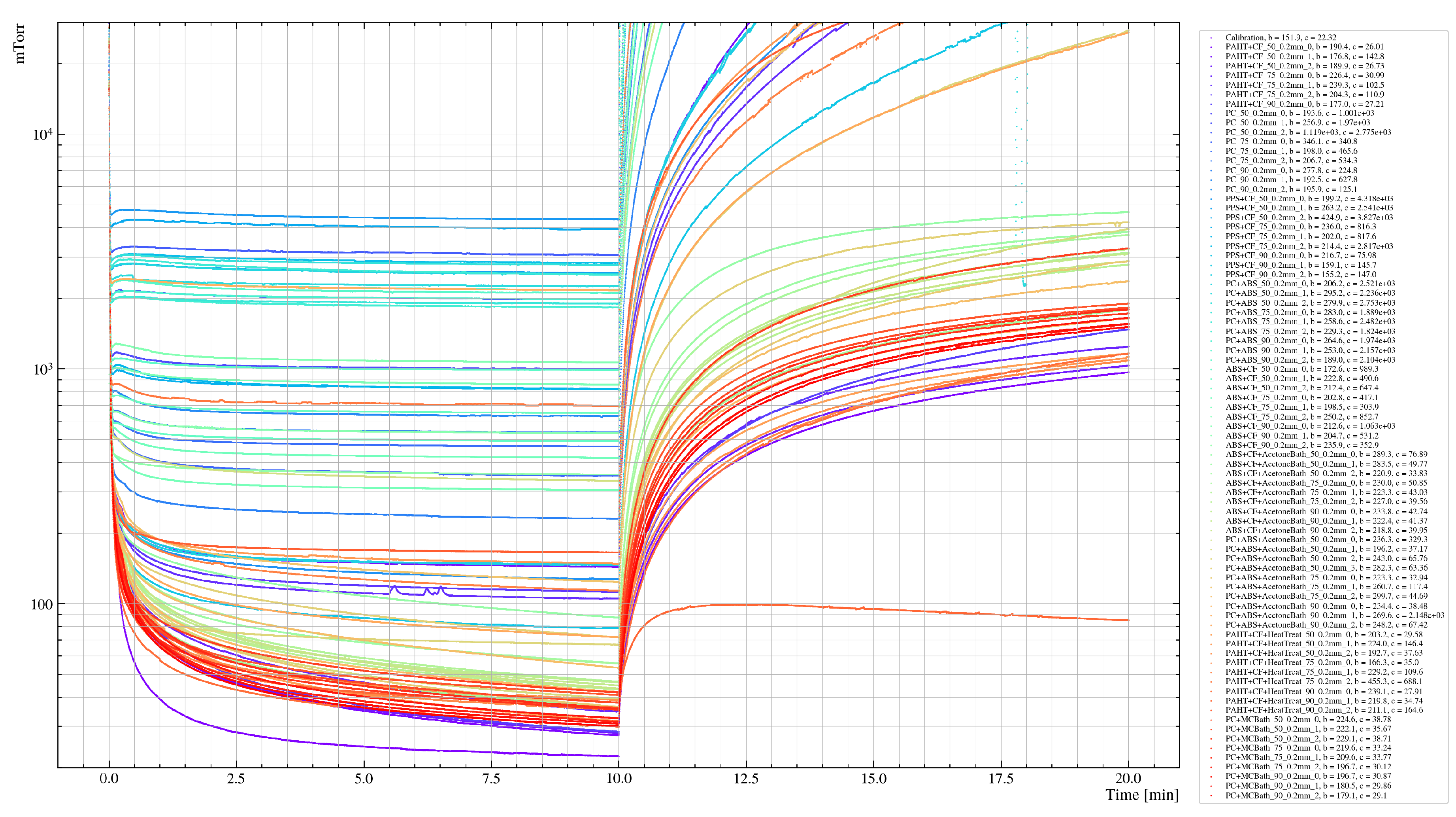
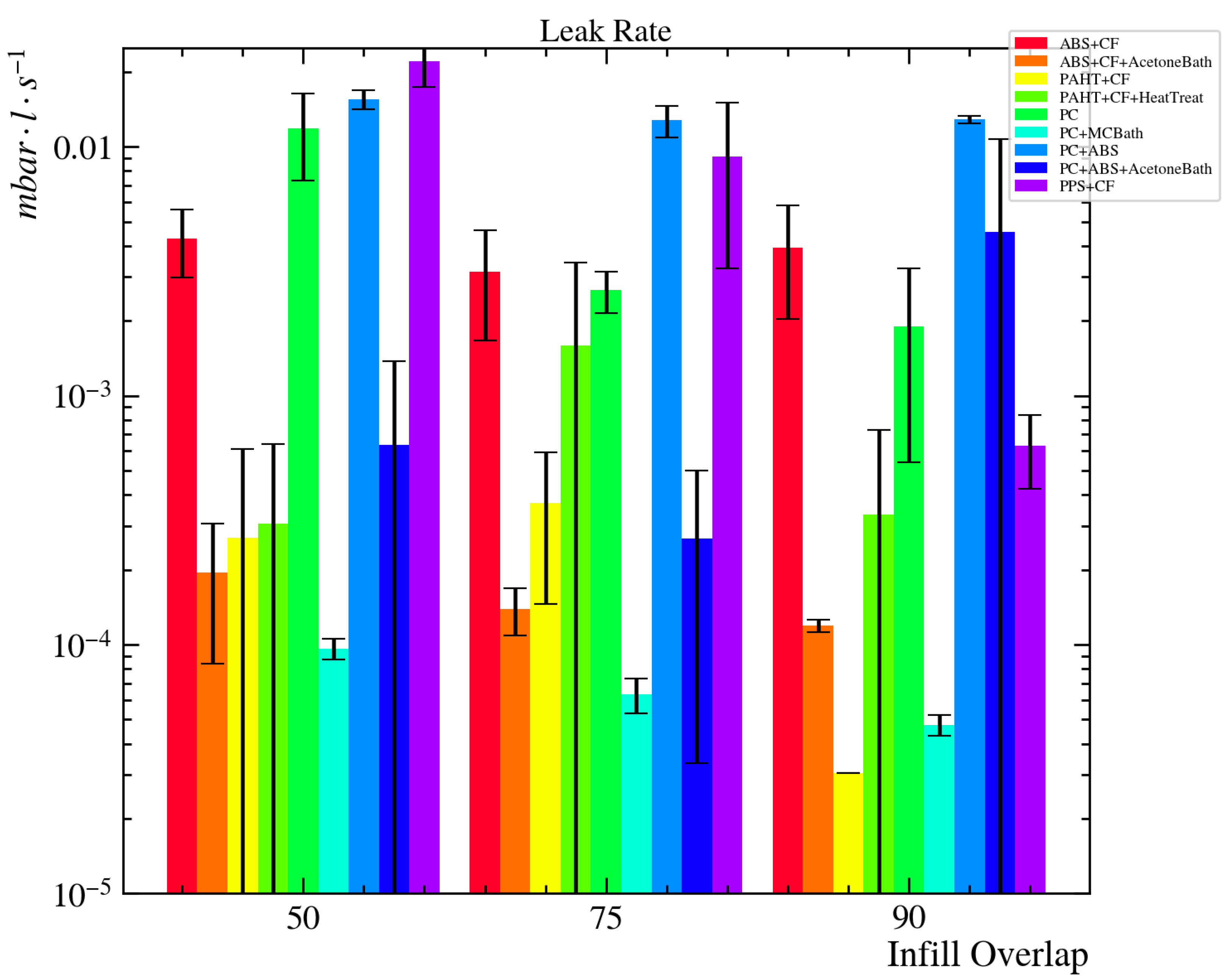
Three test vessels were printed in each of five filaments: 3DXTech’s Acrylonitrile Butadiene Styrene with Carbon Fiber (ABS-CF) [27], Bambu Lab’s Polymide-based PAHT-CF [28], Polymaker’s Polycarbonate-Acrylonitrile Butadiene Styrene blend (PC-ABS) [29], Polymaker’s PolyMax Polycarbonate (PC) [30], and Polymaker’s Fiberon Polyphenylene Sulfide with 10% Carbon Fiber (PPS-CF) [31]. Each of the chosen filaments is advertised by the manufacturers as an option for creating functional parts, is readily available for consumers, and require the FFF machine only to have high temperature printing capabilities and an enclosure. Vessels were then left in lab conditions for at least 20 days to allow for absorption of moisture from the air before undergoing the same measurement and fitting described in Section 2.3. The leak rate for each sample is calculated from Eqn. 1, using the base pressure from the exponential fit of the evacuation curve, the effective pump speed , and the base leak rate , where the effective leak rate is because the sample vessel is in parallel with the base system. After initial measurements, test vessels were post-processed depending on solvent compatibility and left exposed to lab conditions for at least 20 days before the second measurements. Evacuation and leak curves for each sample can be found in Appendix A and the raw data at https://github.com/dvalmassei/FFF_for_LV_apps_data [32]. The average leak rate derived from the evacuation curve of each sample is shown in Figure 4, where each sample contributes a single non-processed and processed curve (except PPS-CF). A table of these results is also available in Appendix B. The reported leak rate is the mean derived from the exponential fits of 10 minute evacuation curves where each sample contributes a single point (each filament typically contributes 3 samples) and have been assigned the standard error. Two of three PAHT-CF test vessels with 90% infill overlap had large voids prior to post-processing, so only one result is shown in Figure 4, explaining the lack of error bar.
4. Discussion
Prior to treatment, engineering grade filaments (i.e. PAHT-CF and PPS-CF) produced parts with the lowest leak rates. This is likely due to the increased print temperatures and the necessity for heated and enclosed printers, leading to better inter-layer adhesion than filaments which cool quickly. These filaments withstand higher temperatures without degrading and without warping when allowed to cool slowly. Under similar conditions, prints with other filaments would fail, prohibiting them from benefiting from the slow layer cooling times. However, due to the chemical resistant nature of engineering grade filaments, they are bad candidates for post-processing. Heat treatment of PAHT-CF increased the leak rate in the test vessels and PPS-CF was insusceptible to either heat treatment or readily available solvents. Due to the cost and difficulty of manufacturing parts from either PAHT-CF or PPS-CF, this study finds them unsuitable for larger applications.
Additionally, evidence suggests that increased infill overlap decreases leak rate, which is likely due to a decreased porosity. While increasing infill overlap too much leads to faulty prints, 90% infill overlap produces suitable and reliable parts from most filaments. Furthermore, parts with higher infill overlap lead to smaller error in the leak rate, implying that higher infill overlap leads to greater consistency and uniformity across parts.
With leak rates falling mostly in the range , ABS-CF and PC can be suitable for low vacuum applications. Prior to post-processing leak rates for all samples of ABS-CF and PC fell between and . The hybrid PC+ABS samples leaked at a rate of . The leak rate for PC+ABS improved by about a factor of 3 after post-processing, but the increased error in all three tested infill overlap settings suggests the exposure to a solvent compromises these vessels. After processing ABS-CF and PC in baths of acetone and methylene chloride respectively, leak rates fell to . PC with 90% infill overlap treated in a bath of MC produced the most vacuum tight test vessels with a leak rate . All three tested infill overlaps also produced measurements with error for PC, suggesting a high level of reproducibility.
5. Conclusions
Of the five thermoplastics tested in this study, PC is found to be the most suitable for vacuum application. The author recommends printing with 2 perimeters, rectilinear infill, line width, layer height, and infill overlap to promote success. Parts should be designed to accommodate 2 interior and 2 exterior perimeters and at least of infill. These considerations ensure there is plenty of material to limit large voids. Under these conditions, vessels can be expected to have leak rates of , though can be reduced to by increasing infill overlap to . The long term stability and scalability of the presented methods is currently under investigation on the 1 liter scale with the scanning Cherenkov detector subsystem developed for the MOLLER experiment.
Author Contributions
Conceptualization, D.C.V.; Methodology, D.C.V.; Software, D.C.V.; Validation, D.C.V. and M.L.P.; Formal Analysis, D.C.V.; Investigation, D.C.V.; Resources, M.L.P.; Data Curation, D.C.V.; Writing – Original Draft Preparation, D.C.V.; Writing – Review & Editing, D.C.V. and M.L.P.; Visualization, D.C.V.; Supervision, M.L.P.; Project Administration, M.L.P.; Funding Acquisition, M.L.P. All authors have read and agreed to the published version of the manuscript.
Funding
This work was supported by National Science Foundation awards 2012995, 2013023, and 2412931.
Data Availability Statement
The original data presented in the study are openly available in GitHub at https://github.com/dvalmassei/FFF_for_LV_apps_data [32].
Acknowledgments
DCV would like to thank Ian Ho, Henry Claesson, and Matthew Tolbert for their valuable discussion of these techniques throughout the course of this project.
Conflicts of Interest
The authors declare no conflicts of interest.
Abbreviations
The following abbreviations are used in this manuscript:
| ABS | Acrylonitrile Butadiene Styrene |
| AM | Additivie Manufacturing |
| CF | Carbon Fiber |
| FFF | Fused Filament Fabrication |
| IPA | Isopropyl Alcohol |
| MC | Methylene Chloride |
| MEX | Material Extrusion |
| PAHT | High Temperature Polyamide |
| PC | Polycarbonate |
| PLA | Polylactic Acid |
| PP | Polypropylene |
| PPS | Polyphenylene Sulfide |
| VPP | Vat Photopolymerization |
Appendix A. Evacuation and Leak Curves by Sample
Figure A1.
Evacuation and leak curves for each tested sample.
Appendix B. Leak Rates by Filament Type
Appendix B.1. Unprocessed Leak Rates

Table A1.
Leak rates for unprocessed samples.
| Filament | Infill Percentage | Unprocessed Leak Rate | Std. Dev | Error |
|---|---|---|---|---|
| ABS+CF | 50 | 3.013E-03 | 9.137E-04 | 5.275E-04 |
| 75 | 2.204E-03 | 1.038E-03 | 5.993E-04 | |
| 90 | 2.750E-03 | 1.323E-03 | 7.640E-04 | |
| PAHT+CF | 50 | 1.880E-04 | 2.408E-04 | 1.390E-04 |
| 75 | 2.595E-04 | 1.573E-04 | 9.081E-05 | |
| 90 | 2.144E-05 | |||
| PC | 50 | 8.306E-03 | 3.183E-03 | 1.838E-03 |
| 75 | 1.863E-03 | 3.514E-04 | 2.029E-04 | |
| 90 | 1.332E-03 | 9.535E-04 | 5.505E-04 | |
| PC+ABS | 50 | 1.089E-02 | 9.284E-04 | 5.360E-04 |
| 75 | 8.962E-03 | 1.301E-03 | 7.509E-04 | |
| 90 | 9.022E-03 | 3.365E-04 | 1.943E-04 | |
| PPS+CF | 50 | 1.553E-02 | 3.287E-03 | 1.898E-03 |
| 75 | 6.412E-03 | 4.137E-03 | 2.389E-03 | |
| 90 | 4.412E-04 | 1.456E-04 | 8.404E-05 |
Appendix B.2. Post-Processed Leak Rates
Table A2.
Leak rates for post-processed samples.
| Filament | Infill Percentage | Post-Processed Leak Rate | Std. Dev. | Error |
|---|---|---|---|---|
| ABS+CF | 50 | 1.368E-04 | 7.799E-05 | 4.503E-05 |
| 75 | 9.721E-05 | 2.073E-05 | 1.197E-05 | |
| 90 | 8.349E-05 | 4.999E-06 | 2.886E-06 | |
| PAHT+CF | 50 | 2.144E-04 | 2.337E-04 | 1.349E-04 |
| 75 | 1.120E-03 | 1.281E-03 | 7.394E-04 | |
| 90 | 2.344E-04 | 2.759E-04 | 1.593E-04 | |
| PC | 50 | 6.755E-05 | 6.369E-06 | 3.677E-06 |
| 75 | 4.411E-05 | 7.079E-06 | 4.087E-06 | |
| 90 | 3.342E-05 | 3.174E-06 | 1.833E-06 | |
| PC+ABS | 50 | 4.457E-04 | 5.227E-04 | 3.018E-04 |
| 75 | 1.872E-04 | 1.638E-04 | 9.457E-05 | |
| 90 | 3.198E-03 | 4.333E-03 | 2.502E-03 | |
| PPS+CF | 50 | |||
| 75 | ||||
| 90 |
References
- AL-Hasni, S.; Santori, G. 3D Printing of Vacuum and Pressure Tight Polymer Vessels for Thermally Driven Chillers and Heat Pumps. Vacuum 2020, 171, 109017. [Google Scholar] [CrossRef]
- Chaneliere, T. Vacuum Compatibility of ABS Plastics 3D-Printed Objects. Research report, CNRS, Laboratoire Aimé Cotton, 2017. Available online: https://hal.science/hal-01599113.
- Domingues, A.; Martínez-Carboneres, A.; Carlson, S. Evaluation of 3D-Printed Plastics for Ultra-High Vacuum Applications: Outgassing, and Residual Gas Analysis. Vacuum 2025, 233, 113970. [Google Scholar] [CrossRef]
- Povilus, A.P.; Wurden, C.J.; Vendeiro, Z.; Baquero-Ruiz, M.; Fajans, J. Vacuum Compatibility of 3D-Printed Materials. J. of Vacuum Sci. & Technology A 2014, 32, 033001. [Google Scholar] [CrossRef]
- Zwicker, A.P.; Bloom, J.; Albertson, R.; Gershman, S. The Suitability of 3D Printed Plastic Parts for Laboratory Use. Am. J. of Phys. 2015, 83, 281–285. [Google Scholar] [CrossRef]
- Li, J.; Mcpartland, T.; Gutierrez, B.; Pedersen, J.; Zhou, Y. Additive Manufacturing for Ultra-High Vacuum Components: Leveraging Photo-Polymer Resin Technologies. Vacuum 2024, 220, 112769. [Google Scholar] [CrossRef]
- Mayville, P.J.; Petsiuk, A.L.; Pearce, J.M. Thermal Post-Processing of 3D Printed Polypropylene Parts for Vacuum Systems. J. of Manufacturing and Mater. Processing 2022, 6. [Google Scholar] [CrossRef]
- Radić, A.; Lambrick, S.M.; Rhodes, S.; Ward, D.J. On the Application of Components Manufactured with Stereolithographic 3D Printing in High Vacuum Systems. Vacuum 2025, 232, 113809. [Google Scholar] [CrossRef]
- Gao, X.; Qi, S.; Kuang, X.; Su, Y.; Li, J.; Wang, D. Fused Filament Fabrication of Polymer Materials: A Review of Interlayer Bond. Additive Manufacturing 2021, 37, 101658. [Google Scholar] [CrossRef]
- Gordeev, E.G.; Galushko, A.S.; Ananikov, V.P. Improvement of Quality of 3D Printed Objects by Elimination of Microscopic Structural Defects in Fused Deposition Modeling. PLOS ONE 2018, 13, 1–19. [Google Scholar] [CrossRef]
- Tao, Y.; Kong, F.; Li, Z.; Zhang, J.; Zhao, X.; Yin, Q.; Xing, D.; Li, P. A Review on Voids of 3D Printed Parts by Fused Filament Fabrication. J. of Mat. Res. and Technology 2021, 15, 4860–4879. [Google Scholar] [CrossRef]
- Heikkinen, I.T.; Marin, G.; Bihari, N.; Ekstrum, C.; Mayville, P.J.; Fei, Y.; Hu, Y.H.; Karppinen, M.; Savin, H.; Pearce, J.M. Atomic Layer Deposited Aluminum Oxide Mitigates Outgassing from Fused Filament Fabrication–Based 3-D Printed Components. Surf. and Coatings Technology 2020, 386, 125459. [Google Scholar] [CrossRef]
- Structure Probe Inc.. Vacseal High Vacuum Leak Sealant, Aerosol, 2025. Available online: https://www.2spi.com/item/05051-ab/vacseal/.
- Garg, A.; Bhattacharya, A.; Batish, A. Chemical Vapor Treatment of ABS Parts Built by FDM: Analysis of Surface Finish and Mechanical Strength. The Int. J. of Adv. Manufacturing Technology 2017, 89, 2175–2191. [Google Scholar] [CrossRef]
- Mu, M.; Ou, C.Y.; Wang, J.; Liu, Y. Surface Modification of Prototypes in Fused Filament Fabrication using Chemical Vapour Smoothing. Additive Manufacturing 2020, 31, 100972. [Google Scholar] [CrossRef]
- Valerga Puerta, A.P.; Fernandez-Vidal, S.; Batista, M.; Girot, F. Fused Deposition Modelling Interfacial and Interlayer Bonding in PLA Post-Processed Parts. Rapid Prototyp. J. 2019, 26, 585–592. [Google Scholar] [CrossRef]
- MOLLER Collaboration. ; Benesch, J.; et al. The MOLLER Experiment: An Ultra-Precise Measurement of the Weak Mixing Angle Using Møller Scattering, 2014. [Google Scholar] [CrossRef]
- Riordan, S.; et al. Study of Light Backgrounds from Relativistic Electrons in Air Light-Guides. Nuclear Instruments and Methods in Physics Research Section A: Accelerators, Spectrometers, Detectors and Associated Equipment 2018, 896, 96–102. [Google Scholar] [CrossRef]
- Lin, Y. Process/Structure/Property Relationships of Semi-Crystalline Polymers in Material Extrusion Additive Manufacturing. Phd dissertation, Virginia Tech, 2024. 10919/118414.
- Bambu Lab USA. Bambu Studio, 2024. Available online: https://bambulab.com/en/download/studio.
- Bambu Lab USA. Bambu Lab X1E 3D Printer, 2024. Available online: https://bambulab.com/en/x1e.
- Cingesar, I.K.; Marković, M.P.; Vrsaljko, D. Effect of Post-Processing Conditions on Polyacrylate Materials used in Stereolithography. Additive Manufacturing 2022, 55, 102813. [Google Scholar] [CrossRef]
- CP Lab Safety. ABS Chemical Compatibility, 2025. Available online: https://www.calpaclab.com/abs-chemical-compatibility/?srsltid=AfmBOoqPdxxVHN2j4Bhekl9kKHE2DErYsUD4hfj6TEAfbu3fxVg3xkT3.
- CP Lab Safety. Polycarbonate Chemical Compatibility, 2025. Available online: https://www.calpaclab.com/polycarbonate-chemical-compatibility-chart/?srsltid=AfmBOorKWyth8XOaDf8YZHeMkPqYVN26w0WggqM3k3nwZnqmr68_3yIv.
- Sobolak, M.; Połowniak, P. 3D-Printed Prototypes of ABS Gears with Improved Durability; [Prototypy kół zębatych z ABS o zwiększonej trwałości wykonane metodą druku 3D]. Polimery/Polymers 2025, 70, 468–474. [Google Scholar] [CrossRef]
- Pazhamannil, R.V.; Govindan, P.; Edacherian, A.; Hadidi, H.M. Impact of Process Parameters and Heat Treatment on Fused Filament Fabricated PLA and PLA-CF. Int. J. on Interact. Des. and Manufacturing 2024, 18, 2199–2213. [Google Scholar] [CrossRef]
- 3DXtech. CarbonX ABS+CF, 2025. Available online: https://www.3dxtech.com/products/carbonx-abs-cf-1?srsltid=AfmBOoo2WkeA-7Wy5Jc5dg6yq-_h5fjMXq4lXG9au_EloX-HS4i9NK_r.
- Bambu Lab USA. PAHT-CF, 2025. Available online: https://us.store.bambulab.com/products/paht-cf.
- Polymaker, US. Polymaker PC-ABS, 2025. Available online: https://us.polymaker.com/products/polymaker-pc-abs.
- Polymaker, US. PolyMax PC, 2025. Available online: https://us.polymaker.com/products/polymax-pc.
- Polymaker, US. Fiberon PPS-CF10, 2025. Available online: https://us.polymaker.com/products/fiberon-pps-cf10.
- Valmassei, D.C.; Pitt, M.L. FFF for Low Vacuum Applications - Data, 2025. Available online: https://github.com/dvalmassei/FFF_for_LV_apps_data.
Figure 1.
Test vessel cross section technical drawing [mm].
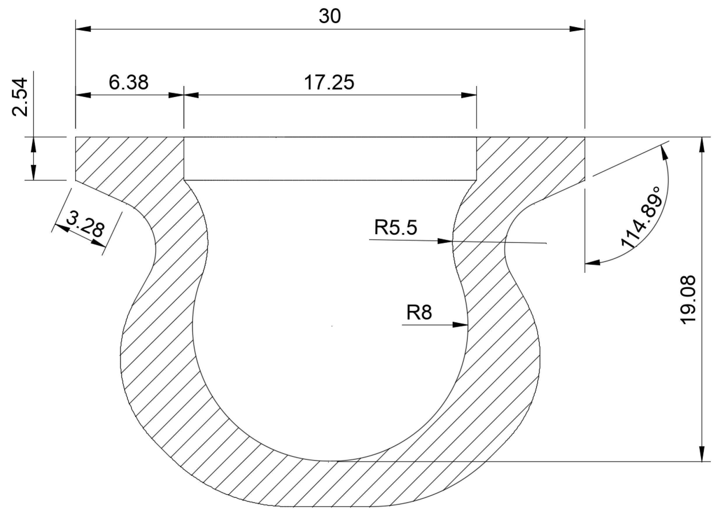
Figure 2.
Vacuum diagram for test vessel setup (left) and image of vacuum system in the lab (right). All connections are ” Yor-Lok fittings, except KF-16 flanges at the sample and the convectron.
Figure 2.
Vacuum diagram for test vessel setup (left) and image of vacuum system in the lab (right). All connections are ” Yor-Lok fittings, except KF-16 flanges at the sample and the convectron.
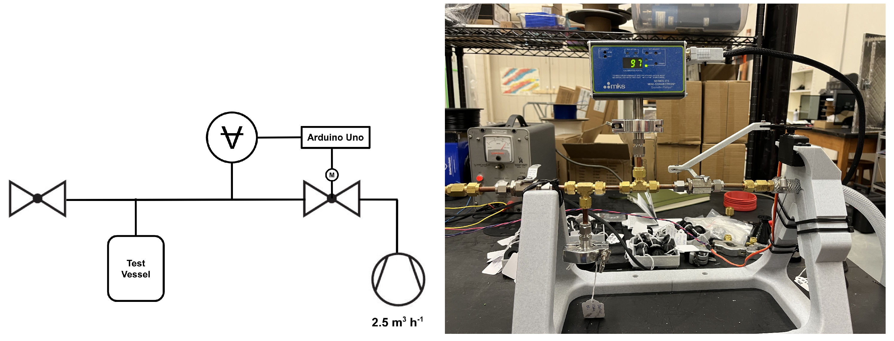
Figure 3.
Plot of vacuum pressure vs. time for a evacuation on vacuum system with Yor-Lok cap on the sample arm, followed by of isolation from the vacuum pump.
Figure 3.
Plot of vacuum pressure vs. time for a evacuation on vacuum system with Yor-Lok cap on the sample arm, followed by of isolation from the vacuum pump.
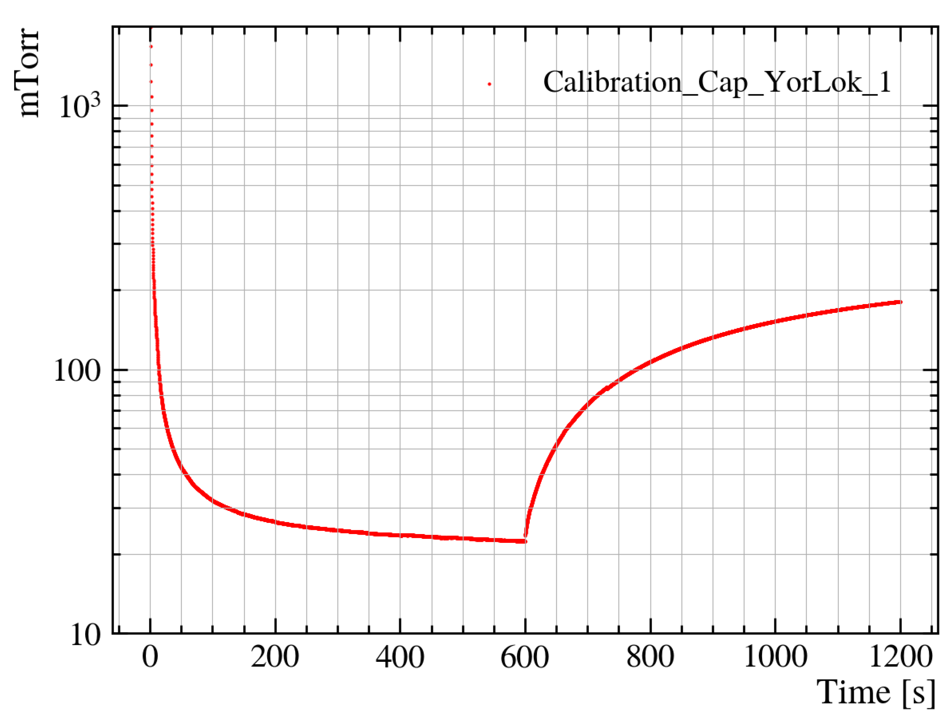
Figure 4.
Average leak rates with standard error derived from exponential fits of evacuation curves for ABS+CF, PAHT+CF, PC, PC+ABS, and PPS+CF. Results are shown for both non-processed and post-processed samples where ABS+CF and PC-ABS samples were solvent smoothed in acetone, PC samples were solvent smoothed in methylene chloride, and PAHT+CF samples were heat treated.
Disclaimer/Publisher’s Note: The statements, opinions and data contained in all publications are solely those of the individual author(s) and contributor(s) and not of MDPI and/or the editor(s). MDPI and/or the editor(s) disclaim responsibility for any injury to people or property resulting from any ideas, methods, instructions or products referred to in the content. |
© 2025 by the authors. Licensee MDPI, Basel, Switzerland. This article is an open access article distributed under the terms and conditions of the Creative Commons Attribution (CC BY) license (http://creativecommons.org/licenses/by/4.0/).
Copyright: This open access article is published under a Creative Commons CC BY 4.0 license, which permit the free download, distribution, and reuse, provided that the author and preprint are cited in any reuse.


