
Submitted:
05 November 2025
Posted:
07 November 2025
You are already at the latest version
Abstract
This article presents the design process and subsequent structural analysis for for Halls 3, 4, and 6 of the Fira de la Gran Vía in Barcelona. Close collaboration between the architectural and structural teams resulted in a cost-effective solution that remains relevant twenty-five years after completion. Each structural component is examined in detail, considering its behavior, preliminary sizing, and the rationale behind its fabrication, transportation, and rapid on-site assembly—critical given the client’s tight schedule. This article also describes how structural details were interpreted and realized under the applied stresses and conditions, including instances that required unconventional approaches. Furthermore, the prestressing of the longitudinal frames is presented as a strategy that contributed to reducing the steel structure’s cost during construction. The paper emphasizes the creation of architecture from the ground up, a process often overlooked in the pursuit of a building’s form and function.
Keywords:
metal structure
; metal prestressing
; large-span structure
; modular structure
; structural design
1. Introduction
Until around 1998, Fira Barcelona was limited to the area surrounding Avenida Maria Cristina. This site incorporates much of the infrastructure originally constructed for the 1929 International Exhibition [1,2], and has remained in continuous operation since the company’s establishment in 1932. The original buildings span a substantial area—from the Venetian Towers [3] to Passeig Jean Forastier, —covering approximately 15.3 ha of exhibition space.
Over time, Barcelona expanded southwards [4], and what had once been the city’s outskirts—framed by Montjuïc Mountain, Poble Espanyol [5,6] and numerous industries, many textile —gradually transformed into a new urban center. This area came to include the Plaza de España railway station [7] (1926), the Las Arenas bullring [8] (1900), and, later various hotels, such as the Catalonia Plaza [9] (1993) serving not only the Fira, but also the nearby Sants station and the city of Barcelona at large. Several office buildings along Avenida de Tarragona, along with La Caixa’s project at Casa Ramona [10,11] (2002) —which became the first CaixaForum in Spain— and the conversion of the Las Arenas Bullring into a shopping center [12,13] (2011), together with other smaller urban projects, ultimately defined this edge of the city. These interventions enabled Barcelona to extend its boundaries toward the neighboring city of L’Hospitalet de Llobregat. Recent actions by the City Council at the former Can Batlló factory complex [14], combined with the construction of the City of Justice (2009), have blurred the boundary between the two cities and reinforced the area’s urban significance.
Despite these changes, Fira Barcelona 1 has long constituted an almost impenetrable barrier between Poble-sec and Sants, affecting daily life for local residents. The relocation of the exhibition halls to L’Hospitalet, together with new projects proposed by Fira de Barcelona for the former site [15,16], aims to reconnect this part of the city with Sants. Montjuïc Mountain, the Olympic ring and the cemetery, however, continue to serve as natural boundaries between the city and the Zona Franca.
In 1993, Fira 2000 S.A. was established to begin relocating Fira Barcelona to its new site, situated between Avenida de la Zona Franca, Carrer del Foc, Carrer de les Ciències, and Avenida de Joan Carles I. The area, located on the opposite side of Montjuïc and spanning both Barcelona and L’Hospitalet, comprised parcels that were either vacant or had to be acquired from private owners, necessitating the demolition of existing buildings. The entire relocation and development process extended over approximately 25 years. The projects required the acquisition of the Bauhaus company building on Avenida de la Zona Franca, several semi-detached and single-family homes near Gran Vía, and a number of industrial warehouses.
In 1995, the first pavilion—now referred to as Nave 2—was constructed near the junction of Carrer del Foc and today’s Joan Carles I Avenue. Measuring approximately 319 × 97 m, the building was originally conceived for small-scale exhibitions with limited audience capacity. Its main nave spans 69 m. This project marked the first step in shaping the site as it is recognized today, later altered through a renovation commissioned to the renowned Japanese architect Toyo Itō [18], who was entrusted with designing a unifying intervention linking all the buildings [19,20,21].
The structures now known as Naves 3 [22], 4 and 6 —shown in Figure 1 and originally designated as Naves 2, 3, and 4— were designed by architects Ramón Farrè-Escofet and Isidre Vinyes-Llebot of the firm then called Projectes Urbans Farrè Escofet i Associats S.L. These buildings correspond to the second and third phases of the relocation of Fira Barcelona pavilions from the Montjuïc fountains to their current site at Fira Gran Via. The exhibition area developed during these phases extends over approximately 10.9 ha. Hall 3 was inaugurated in 2001, followed by Halls 4 and 6—the third phase of expansion—in 2005. Subsequent phases integrated these halls with new facilities and introduced several office buildings, which lie beyond the scope of this publication. Today, the Fira complex occupies a total area of 410,000 m², with a gross exhibition surface exceeding 24 ha., and ranks among the most prominent trade fair venues in Europe.
Hall 3 is the primary focus of this article. However, it is worth noting that phases 2 and 3 were complemented by additional structures, including Hall 2.2—an extension of Hall 2—as well as the Nexus 1 and Nexus 2 buildings located between exhibition halls, a lobby building, a changing-room facility, several underground parking structures, and service galleries for utilities. Altogether, the intervention described in this article occupies approximately 430 x 370 m², corresponding to a site area of about 141,000 m².
The Catalan firm Robert Brufau i Associats S.A. was responsible for the structural design of the Nave 3 project by Projectes Urbans Architecture, under the direct supervision of Dr. Robert Brufau i Niubó. [23,24]. Construction works were developed by Dragados, prior to its merger with ACS [25]. This article addresses the design process and the subsequent construction of the structural module, which is repeated up to 16 times, including adaptations employed to close the building’s terminal ends.
2. General Description of the Structural Layout and its Sizing [26]
The structural unit —hereafter referred to as the TYPE MODULE—initially measured 103 x 49m², and was later slightly adjusted in each hall to align with the roadway layout. The roof reaches a height of 15 m across most of its span, interrupted only occasionally by metal structural elements. At the midpoint of each type module, a 13x13m² central area rises more than 4 m in height. This central square accommodates four reinforced concrete pillars, each 800 mm in diameter, which not only partially obstruct natural light but also support two floors intended for technical installations with high live-load requirements.
To cover this typical module, the structure was initially conceived to span façade to façade. The warehouse measures103x390 m, with the shorter 103 m side, corresponding to what is subsequently defined as the LONGITUDINAL FRAME. A 103 m span without central supports would have been structurally ambitious; however, the first and perhaps most important critical design decision was to recognize that that introducing one or two central supports would substantially reduce costs while preserving required functional flexibility for the warehouse. Each kg/m² reduction in structural weight yielded a saving of 8 modules × 49 m × 103 m × 1 kg/m² × 2.2 €/kg = 88,827 € [28,29] based on year-2000 prices. Considering a span-to-depth ratio of L/15, a beam without central supports would require trusses nearly 7 m deep, demanding large cross-sections to satisfy slenderness requirements for the least-stressed elements. Furthermore, this would result in a simply supported element with substantial reaction forces, which would also have to support two slabs at midspan.
The decision to place two supports at the midpoint —creating a 45 m – 13 m – 45 m module rhythm —effectively generated the equivalent of a 45 m span pinned–fixed beam. The central 13 m segment, as shown in Figure 2, prevents the negative moment from reversing at the hall’s midpoint. Therefore, comparing a 103 m simply supported beam with a 45 m span pinned–fixed beam yields the results summarized in Table 1.
In Table 1, it should be noted that the calculations contain small approximations that do not diminish the validity of the comparison. The analysis assumes a unit beam width; thus, any increase in width would proportionally increase the calculated values. A unit load condition is also considered, meaning that higher loads would scale the results accordingly. However, the self-weight of the steel structure would naturally be greater in the first configuration than in the second, thereby accentuating the differences and further improving the efficiency of the shorter-span solution. Regarding the differences shown in the last column, the 45 m beam configuration reduces the bending moment by approximately 81% compared to the 103 m beam configuration, the required moment of inertia by 97%, and the indicative structural depth by 66%. As steel cost is derived from these parameters, the design can be considered appropriate if the final steel weight remains within a reasonable range—typically between 30 and 80 kg/m² [30] according to literature and professional experience, or even lighter for roofs intended solely for maintenance access [31]. Finally, it is worth noting that greater structural depth would reduce the interior clearance of the nave or, alternatively, increase façade height. Consequently, the overall economic advantage of the 45 m solution is even greater. Another feasible option would have been to divide the 103m span into three equal segments of 34.3 m, at the expense of a slightly larger central span.
Once it was determined that a span of approximately 45 m could accommodate the required exposure types, a module repeated every 49 m was adopted to position the structural modules on site while meeting architectural constraints. In the transverse direction, the spans adopt a 36 m–13 m–36 m–13 m rhythm, producing column-free areas of 103 m × 36 m or 45 m × 390 m. The next step was to determine the optimal way to cover each module transversely —hereafter referred to as the TRANSVERSE FRAME. The space required central lighting as well as a smoke venting for fire safety. It was estimated that providing a designated smoke vent every 49 m would be sufficient. Natural lighting requirements were minimal, since these warehouses require little daylight. The space above the roof plane was required to remain fully open and unobstructed. Structural elements were intentionally kept clear of the skylight —which also serves as a smoke vent [32] —both to minimize fire exposure and to maintain a visually clean architectural space.
A system of symmetrical, industrially adaptable cantilevers with a span of 11.8 m on either side of the 13 m central space was adopted, resulting in an 11.8 m – 13 m – 11.8 m configuration. The remaining 12.4 m, up to 49 m, accommodate the central skylight. Figure 3 shows a planar analysis of the transverse frame, indicating that the lower fibers are in compression along the entire span. Consequently, when this model is converted into a truss, transverse bracing is required to prevent local buckling. The skylights were designed with simple frames; as these are shorter-span elements, their behavior is discussed later in the calculation section.
The final decision concerned material selection. Steel framing is widely recognized as the most suitable solution for large-span structures, due to its high structural performance, minimal need for temporary supports or scaffolding, and ease of assembly. However, it is vulnerable to fire exposure, making the profile geometry—commonly referred to as “massiveness”—a critical design parameter. Because the structural elements were left exposed, intumescent paint was required. The higher the fire-resistance rating (in minutes), the larger the necessary cross-sectional area and the thicker the intumescent coating. To reduce the thermal exposure on the roof, CFD simulations [33,34] were conducted, showing that at a minimum height of 15 m, the roof could achieve an R-30 fire rating. This approach significantly reduced the amount of steel and intumescent coating required, lowering overall costs. However, structural elements up to 9 m in height were required to achieve 90 minutes of fire resistance, based on several factors: proximity to potential heat sources, the strategic location of emergency exits, and the nearby fire station, which ensures rapid response thanks to the automatic detection systems in these warehouses. It is assumed that if a fire originates approximately 1 m above floor level, the heat mixes with ambient air and dissipates as it rises— provided there is no physical barrier, such as an unvented roof, to trap it.
Another key design factor was ensuring structural stability against accidental impacts, such as collisions from low-speed maintenance or material-handling vehicles operating within the Fira complex. Reinforced concrete was specified up to a height of 9 m to ensure fire resistance through calibrated protective coatings that meet minimum code requirements. Each standard module comprised eight primary supports, supplemented by secondary supports along the façades. This arrangement limited the initial use of concrete to these key elements, while other buildings in the complex employed it more extensively. The construction sequence allowed reinforced concrete elements to be erected first, while the steel structure was prefabricated in the workshop, significantly reducing on-site construction time.
The longitudinal frame was designed as a Warren-type truss girder [35], selected because it provides a more architecturally expressive form than other common truss types such as Pratt or Howe, which are frequently used in industrial buildings. For the transverse frames, a lighter Warren girder was also adopted, repeated at every third triangle of the longitudinal frame’s filler bars. This approach is further justified by the limitation that the roof sheets could not span more than 5 m.
Other essential elements—such as the wind beams, façades, and counterbalanced cantilevers—require only brief mention at this stage, as their detailed behavior is addressed later in the calculation section. These include the wind beam, the façade, and the counterbalanced cantilever.
3. Materials and Methods: Structural Calculation Process
In the previous section, the components of the Structural Module Type [36] were described. Two additional steps precede the structural outline: first, a preliminary sizing of each element; and second, the final 3D calculation. From this point onward, it becomes evident that the outcome clearly reflects a strong integration between architecture and structure—a synergy that has historically yielded excellent results, as illustrated in 18 Years with the Architect Louis I. Kahn [37] and, more broadly, in Architects + Engineers = Structures [38]. This thoughtful integration is clear in the careful detailing of edge conditions, the strategic addition of reinforcing elements (as explained later), and the consistent effort to harmonize each structural proposal with the architecture—whether by complementing, concealing, or emphasizing it, including the application of finishes that express its structural hierarchy.
3.1. Pre-Dimensioning
Longitudinal Frame As mentioned previously, a depth of 3m was initially considered sufficient for this truss girder [39]. However, the stringent deformation limits imposed by its slope and the gravity-based drainage system (Geberit —which did not permit excessive deflections that might compromise capacity—necessitated the addition of a lower reinforcement chord. The design of this lower chord was based on the moment diagram shown in Figure 2, which displays three parabolic segments separated by two zero- moment points near the central double support. These points arise from the two pillars spaced 13 m apart. Because this new chord was not laterally braced by the transverse—and given the almost flat roof—the reinforcement was positioned below the lower chord of the Warren truss. The maximum vertical offset was set at 1,500 mm, resulting in a maximum distance of 4,500 mm between the axis of the upper and that of the new lower chord.
The first and third spans of the truss are subjected to tension, while the central 13 m span between the pillars is in compression and therefore requires stabilization. Vertical uprights are provided to achieve this: under tension, they act as deflectors, while under compression they serve as transverse stabilizers for the compressed chord. During the detailed design phase, the option of maintaining the central reinforcement above the roof (i.e., in tension) was considered [40]. This decision was ultimately discarded to avoid interrupting the roof at the nave’s center, which could have caused water infiltration. It should be noted that each longitudinal frame supports a tributary width of 24.5 m, which also justifies the increase in depth from 3 m to 4.5 m.
To refine the geometry, the lower chord of the 13m central span was divided into 6 sections, resulting in triangles measuring 2.1666m. Extrapolating this pattern to the full 103 m span results in approximately 48 triangles, thereby establishing the geometry of the longitudinal frame, shown in Figure 4. The frame is planar and predominantly composed of double-T (open) profiles, except for the lower extensions, which are designed as closed tubular steel sections in the final project.
Transverse Frame: The compressed lower chord was stabilized using its own geometry, leading to the adoption of a multi-plane structure. Its intersection with the longitudinal frame forms a triangular configuration, while the cantilever supporting the skylights terminates in an edge. Thus, the intermediate section assumes a trapezoidal shape, as the lower chord forms a V-shaped geometry. Between the two frames of each structural module, a multi-plane beam was included, in this case maintaining a constant triangular section. The upper chords were designed with HEA cross sections to reduce costs and facilitate support for the roof sheeting. The remaining elements consist of small-gauge tubular sections, emphasizing the contrast between the heavier longitudinal structure and the lighter transverse frame. This distinction was expressed architecturally: the longitudinal chords were finished in dark gray, while the transverse chords were painted nearly white. The resulting geometry is shown in Figure 5.
Skylights: The formal design of this seemingly simple element derives directly from the shape of the beam's bending moment diagram. As the element required a central mechanical vent, it could not remain flat. This is also where natural light enters, providing the minimum illumination needed for a pavilion of this type. Accordingly, a frame was introduced, consisting of two inclined pillars—one in each of two consecutive structural modules—and a triangulated, half-moon truss that replicates the bending moment diagram of a two-span pinned beam. The frame is arranged with spacings of 2.16 m, 4.32 m, 2.16 m, and 4.32 m.
In areas where the skylight does not reach the façade, a full-web, variable-section beam is used, with its maximum depth at midspan. This geometry ensures that the roof sheeting is fully supported by the upper flange, while the lower flange remains flat. The final configuration is shown in Figure 6.
Ventilation and Support Cores for the Longitudinal Frames: The galleries —not discussed in this article— required both ventilation and emergency exit. At the same time, the longitudinal frames had to be supported for a load of approximately 150 tons, specifically using a sliding support parallel to their plane to mitigate thermal effects. Additional smaller supports at various heights and positions were also required, including wind beams, counterweighted frames, and entrance lattices.
Architecturally, the entrance was conceived as framed by two concrete triangles, creating a distinctive rhythm along the façade and clearly articulating the access points. Accordingly, two pairs of 200 mm-thick concrete towers were positioned on each façade. At the outermost vertices, the corner was solidified to facilitate formwork and enhance structural strength, as all previously described forces converge at these points across different heights. The ventilation cores rise to the full façade height, reaching 12.7 m. Each core includes an emergency exit through a door integrated within its walls. Access to these cores also required structural support from one of the gallery walls.
Counterbalanced and Access frames: Between each structural concrete triangle and its adjacent one, two façades are formed: a shorter 13 m entrance façade and a longer 37m enclosing façade. Around the entire perimeter of the warehouse, a cantilever extends approximately 6.2 m at a height of +9 m.
This architectural decision reflects the understanding that many users would seek, shaded outdoor spaces—areas protected from rain. It also gives the façade greater depth: the interplay of shadows and cuts in the plane visually reduce the building’s apparent height. To support this cantilever, a counterbalanced structure was adopted for the long façades, conceptually similar to that of a construction crane. Inside the warehouse, another cantilever was built to serve as a service walkway, with an overhang of 2.8 m. This internal structure consists of a 160 mm-thick composite slab enclosed by two sheets—an upper layer forming the roof and a lower layer closing the ceiling below.
Permanent loads could be balanced; however, the variable loads could not. No interior paving was provided, but an allowance of 1 kN/m² was considered. Externally, non-concurrent live loads of 0.40 kN/m², a snow load of 0.40 kN/m², and wind pressure or suction were applied. All load cases were analyzed in accordance with current regulations, resulting in deformations in both directions. This range of deformations determined the required counterweight: the structure was designed to remain as close to horizontal as possible under no additional loads. The deformations were therefore estimated at +/- 15 mm. The frames were fabricated from steel, using HEB-200 sections forming full-web beams spaced at 4 m intervals. Inside, an HEB-200 frame embedded concrete, creating a slab of uniform thickness that appeared relatively thin when viewed from inside the warehouse. The frames were supported by two central pillars, with their ends pinned to allow sliding and to accommodate an expansion joint within the ventilation cores. A rectangular tubular steel beam was placed atop the pillars to allow exposed beams to be welded together, reinforced with handrails and a plate bridge.
Everything described above is illustrated in Figure 7. A Pratt-type lattice was installed on the access frames, reinforcing the idea of entry from the exterior. This element is not discussed further, as it is relatively straightforward.
The cantilever has a double slope: the upper surface directs water outward so that, if downspouts cannot drain accumulated water, it spills off as a “water curtain,” preventing infiltration or ponding that could increase the loads and risk collapse. At the cantilever’s edge, a continuous water collection channel is provided, hidden from street view. The lower surface, which supports the false ceiling, slopes inward, ensuring the downspouts—located between the false ceiling and the roof sheeting—are fully integrated within the cantilever.
Wind Roof Frames and Facades: Above these frames, small rectangular tubular pillars (RHS-120x80x5mm) were installed every 2 m to support the façade cladding. These pillars both carry the façade and provide stability against wind loads acting on the roof plane. To this end, a wind beam was designed, consisting of two planes continuing the roof slopes, spanning 3 m and fully triangulated. This beam connects two modules, with the joints defined as expansion joints featuring a groove parallel to the façade plane.
The structure was then defined and organized, and a calculation model was needed.
3.2. Executive Project
Main Hall: A 3D bar model was developed to perform the structural calculations. In 1999, computers and software were far less capable than they would become just a decade later. The program used was Robot v6, which at the time operated only on MS-DOS. The images attached to this article were imported into the Autodesk Robot 2024 [41,42] under an educational license; the article explains the procedures originally carried out using the program's official license.
It is clear that the model was highly complex for its time, though comparatively simple by today’s standards. It consists of 2,088 bars and 862 nodes. To streamline the analysis, the skylights and façades were omitted; their structural effects, however, were accounted for by applying the corresponding loads.
The roof loads have already been described. For the two floors above the central area, the applied loads were: 2.5 kN/m² for the floor self-weight, 0.80 kN/m² for additional dead loads, and 5.0 kN/m² for live loads. The final calculation model is shown in Figure 8. The structure is supported by only 8 supports —four central supports on the foundation and two at each end on the structural concrete ventilation cores.
Counterbalanced Cantilevers and Wind Roof Beam: The second model included the concrete façade up to level 6, the counterbalanced structure, the steel frame supporting the façade, and the wind-bracing beam above. As shown in Figure 9, vertical stabilization of the wind-bracing beam required placing supports to transfer the load to the first transverse frame; this detail is explained further below. This model comprises 122 nodes and 235 bars.
4. The Expansion Joint
The expansion joint was defined on the façades, specifically in the tubular steel beam—explained later—and in the wind beam. Its behavior at the roof level was initially uncertain, as these joints were positioned adjacent to the ventilation cores, where the longitudinal porches were supported. The expansion joint extended along the wind beam in the roof plane, in the areas without skylights; elsewhere, the joint was entirely omitted. Thus, a longitudinal section along the central axis of bay 2 reveals a continuous structure approximately 400 m long, without any expansion joints. This approach prevents potential rainwater ingress, since movement in the building occurs mainly at the joints—which are typically the points of water entry. Yet the question remains: can a building of such length function without expansion joints? The solution draws on a principle commonly used in mechanical installations, such as long, straight hot water pipes in air-conditioning systems, which may experience thermal variations of up to 100 °C between cold and fully heated states. Since the pipe is made of steel, its thermal elongation can be determined from its coefficient of thermal expansion, α=0.000012°C^-1 and its length:
In this case, the temperature variation was estimated at +/-25ºC over a length of 450m [43]. According to Formula (1), this corresponds to a total elongation of +/-1.35m —a clearly unacceptable figure. In piping systems, this issue is resolved by incorporating expansion loops, or "lyres" [44], which absorb deformation through their geometric configuration. Once it was determined that the skylights could not be supported by a rigid frame due to the complexity of the detail, the support inertia was deliberately minimized. Two HEB sections with the lowest inertia were positioned in the frame plane to create flexible supports. In addition, the pillar bases were articulated at the transverse frame supports to further reduce stiffness, while the half-moon truss geometry ensured the lattice girder transmitted minimal moment to the pillar tops. A thermal analysis over the 450 m span confirmed that stress increases were negligible, validating this approach
The discussion above refers to the thermal expansion in the direction of the transverse frames. As noted earlier, expansion along the longitudinal frame was managed with a reinforced neoprene bearing functioning as a sliding support.
It should also be noted that the roof could be exposed to high temperatures in the event of a fire [45,46]. Although the structure was only fire-protected for 30 minutes [47], the deformation caused by a 500 °C temperature rise was calculated. While the roof would not fail in tension under such accidental conditions, it could potentially collapse if left unsupported. The same formula was applied, this time for a temperature of 500 °C, and it was concluded that the structure would remain stable in both directions, as the end deformations would not cause the supports to disengage from their brackets. Figure 10 below shows the detail of the expansion loops (‘lyres’) formed by the continuous sequence of cantilever, skylight, and cantilever.
5. Final Structural Organization and Adjustment of the General Module at the Ends
Hall 2 did not comprise a whole number of modules, requiring a tailored solution for each façade. At one end, superelevated full-web beams—the same as those used in skylight-free areas—were installed and supported by standard pillars, consistent with the other façades. This intervention is relatively straightforward. However, in the area closest to Gran Vía, the cut occurred within one of the longitudinal frames, leaving only a cantilever spanning three transverse-frame bays. As a result, the structure became destabilized, showing a pronounced tendency to overturn. To counteract this instability, the adjacent changing- room building acted as a counterweight. Although its structure is unbraced, its short spans solid-slab floors ensure stability in both longitudinal and transverse directions. Composite pillars were installed in areas where the pillars were subjected to tension. The foundation was designed for both scenarios—with and without the cantilever—anticipating the possibility that the nave might be removed in the future while keeping the building intact. The structural system described thus far is illustrated in Figure 11.
During the structural calculations for the final project, the roof load—excluding pillars and façades—was estimated at 55 kg/m². As will be detailed later, this was reduced to 50 kg/m² during the construction phase. This is relatively low for a lightweight roof spanning 45 m in one direction and 37 m in the other. Based on the 2000 prices referenced in this article, this corresponds to a material cost of approximately €110/m².
6. Construction Phase
For the assembly process the following decisions were adopted, as described below:
- The concrete pillars had to be poured in a single operation, avoiding a two-stage process. To achieve this, the formwork was braced with guy wires and props at two different heights, and the concrete was poured using a hopper to prevent the material collapse when dropped from a significant height. A plate was placed at the top of each pillar to facilitate the bolted connection of the corresponding uprights of the main longitudinal frame.
- The main longitudinal frame was to be assembled in three sections, with two symmetrical joints located approximately at the point of zero bending moment. Assembly began with the central section, which took priority, as the adjoining sections could not be installed without it.
- The two intermediate sections of the main frame were assembled on the ground, joined to the adjacent triangular pieces in this area, together with the two joists supporting the slab, the pre-fixed corrugated metal decking, reinforcement, and concrete, as well as the upper roof structure Fall-protection elements were also pre-installed. This approach minimized work at height and reduced the risk of potential accidents The entire assembly was then hoisted using a pair of mobile cranes; with the assistance of four mobile platforms, the lifting operation could be completed in just a few minutes. The objective was to hoist the five standard modules in a single day, optimizing the efficiency of the two cranes. Notably, no major accidents occurred during construction. All of the aforementioned assembly work was carried out on the ground prior to hoisting, except for the concrete pouring, which had to be performed at height due to its weight and the need for more powerful—and less readily available—cranes. The lifting process is shown in Figure 12.
- The ventilation cores were assembled using continuous interior and exterior formwork. This work was carried out prior to the installation of the truss girders ends but could also follow the assembly of the pillars and central sections of the longitudinal frame, which house the supply, return, and general installations. Each module included three openings and could represent a potential critical path, as the foundation, gallery, and core had to be completed before any metallic elements could be supported. The central pillars were not supported by the gallery. Figure 13 illustrates the formwork closure process.
- The cantilevers of the transverse frames were only assembled once the longitudinal frames were fully positioned and braced by the central sections of the triangular transverse frames.
- Once the two longitudinal frames were completed, a triangular module was promptly installed at each end to stabilize the still-unconnected beams.
- The transverse cantilevers were installed progressively by bolting them to the flanges of the main truss chords. A layer of paint was applied at each joint to ensure proper friction at the junction [48]. With the aid of two aerial work platforms, a transverse-frame cantilever could be positioned in just ten minutes. The bolted joints were then checked.
- The skylights, together with the remaining substructures, were bolted last.
- The roof sheeting, insulation, and sound-absorbing lower sheeting were installed after completion of the entire structure.
Figure 14 shows the hall in a very advanced stage of construction.
7. Post-Tensioning of the Main Beam On-Site
During the construction phase, an effort was made to reduce the amount of steel used in beams in order to reduce the overall project cost. However, as the project was developed under tight time constraints prior to tendering, it was challenging to identify alternative solutions capable of achieving substantial cost savings. Consequently, a proposal was made to prestress [49] the beams of the main portal. Prestressing has been a common solution in reinforced concrete since Eugène Freyssinet pioneered its development in the mid-19th century [50], but it is far less common in steel lattice girders [51], since steel performs equally well in compression and tension, with sections typically operating close to their allowable stress limits. The same does not apply to concrete: while the maximum allowable compressive stress is typically around 30 N/mm² —only about 10% of its tensile strength—rolled structural steel easily reaches 275 N/mm², and prestressing (high-strength) steel approximately 1,000 N/mm². Consequently, the strength ratio between concrete and prestressing steel is approximately 33, compared with only 3.6 between structural steel and prestressing steel. Therefore, it would not be logical to over-compress concrete in order to reduce tension in steel that is 3.33 times stronger, has a smaller cross-section, and is more expensive. However, in large-span beams where deformation governs the sizing of truss members and elements operate at relatively low efficiency, this reserve of strength can be leveraged to reduce the amount of steel required.
In prestressed concrete, standardized solutions are widely available in commercial catalogs; for steel, however, there is no standardized or widely accepted method to address this issue. The operation resulted in an estimated saving of approximately 5 kg/m² of steel. This figure may seem anecdotal and insignificant, but if we recall the figure mentioned at the beginning of this article—where each kilogram per square meter represented approximately €90,640 in 2002 for Warehouse 2 alone—we quickly realize that it corresponds to a saving of €1,359,600 for the three warehouses, approximately €2,700,000 in today’s terms. This figure already includes the additional cost of the added active steel and its terminals. Further information on both active and passive terminals can be found in the details section. Only the first and third spans were post-tensioned, leaving the central span —subject to negative thermal effects—without additional active reinforcement.
8. Process of Defining Key Details
It is important to start this section by noting that every design decision regarding a detail had a direct impact on both the structure and the workshop fabrication of hundreds of nodes [52]. For instance, adding two stiffeners to the joint between the upper HEA chord of the transverse beams, to prevent web buckling, transformed a seemingly simple design decision into a substantial fabrication task: 2 stiffeners × 2 cantilevers × 2 chords × 4 joints × 13 frames × 6 modules = 576 stiffeners per bay, requiring an additional 115,200mm of weld bead. After converting everything into a standardized system, it became necessary to restore rigor in the definition of the details [53].
Connection between the Horizontal Interior Chord of the Flat Wind-Bracing Beam and the First Transverse Frame: To address this connection without compromising the expansion joint, a bolted joint was designed with a slotted hole and a neoprene washer allowing movement in all directions. As the upper chord was an HEB-140, a UPN-100 was nested within it, enabled by the absence of stiffeners. The bolts were not pretensioned to allow this potential movement; however, a nut-retention mechanism was installed to prevent them from falling. It should be noted that although the deformations could occur in any direction, they were limited to a few millimeters, rendering the resulting eccentricities negligible. The detail is illustrated in Figure 15.1
Anchor Plate Between the Ventilation Core and the Longitudinal Frame: Since the core was built using sliding formwork, it was necessary to design a plate that could be supported by both the reinforcement and the formwork, while remaining flush with the wall face. This plate transmits 1,500 kN to the concrete and, due to the beam’s eccentricity relative to the wall, generates a moment of 225 kNm in the SLS. To control shear, the plate was internally reinforced with two IPN profiles, each capable of independently transferring this vertical load. Studs with threaded heads and legs were also installed to transmit the moment to the supporting structure. After the formwork was removed, an unpainted steel plate remained, serving as the base for a welded metal bracket. This bracket rested on a smaller plate, which was welded around its entire perimeter to the plate left on the wall. The bracket caused tension in its upper portion and compression in its lower portion, with shear transmitted through the two vertical welds. However, these welds were too long to effectively resist the resulting stresses. Due to the challenges of executing the weld on-site and the considerable effort required, slots were provided in the upper portion to reinforce the tensioned area, thereby increasing the effective weld length. If the weld presented uncontrolled defects, this excess would protect the most critical area of the joint, as the compressed weld would still transfer load through direct contact between the two elements. The detail is illustrated in Figure 15.2.
Diagonal Chord Connections in the Main Frames: The truss girder was designed with HEA, HEB, or HEM-300 chords. With some spans exceeding 30 m during the lifting phase, the beams could experience excessive vibrations or even failure due to their low transverse stiffness. To prevent this phenomenon, the HEBs were arranged with the web horizontal and the flanges vertical. This configuration increased the transverse stiffness of the flat beam and also facilitated the bolted connections of the transverse frames. The diagonals were also positioned with the flanges vertical. To facilitate the connections, HEB, IPE, or IPN profiles with depths of 300, 260, or 240 mm were used. This profile catalogue allowed the tension diagonals to be smaller than the compressed diagonals with lower axial forces, and enabled the elevation to represent shear forces at any point along the beam, even distinguishing between compression and tension in consecutive diagonals [54], as illustrated in Figure 4.
The junction details were slightly more complex, with approximately fifteen different cases. At the junctions, a half-circle design was adopted to emphasize that the space was not an industrial warehouse but closer to a salon. This was achieved using a transition plate, which in some cases acted as a bridge to accommodate welds between plates of significantly different thicknesses, or where the diagonal was thinner than the interior width of the HEB. A lattice girder requires larger chords in the center and smaller chords at the ends, while the diagonals follow the opposite pattern —larger at the ends and smaller in the center. The corresponding details are illustrated in Figure 16.
Active and Passive Terminals for Post-Tensioning: The first decision was to designate the passive terminal as the interior one, since access for inserting the jack was limited and the beam itself prevented the use of a crane to position it with the terminal. Meanwhile, the end located on the façade was ideal for working comfortably with a multi-strand jack and allowed the mobile crane to work efficiently from the exterior, moving freely around the building. A system of self-protected strands with PVC sheaths was used, with mortar injected prior to tensioning. This ensured that the sheaths did not pull on the innermost strands or trap them between the stressing cable, which could have resulted in excessive stresses. Subsequently, for bays 3 and 4, the tensioning was completed with final grouting, and the results were satisfactory in both projects.
Thinner ducts were used in the straight sections to reduce material usage, as their primary function was to serve as protective sheaths. In the deviators, or curved sections, ducts were used with an inner diameter matching that of the straight-section ducts. This decision avoided section changes that could cause internal edges or variations in thickness, which might damage some of the strand wires and lead to breakage during the tensioning phase. As its name suggests, it is called deviator because it redirects the force from one direction to another, thanks to the presence of a post at its midpoint. Therefore, the deviator is subjected to forces that generate a bending moment; for this reason, the tube was thickened while remaining flexible enough to achieve the required bending radius.
In this detail, the thickest plates of the entire project were used—specifically, 40 mm thick plates subjected to the active-head forces. These did not exceed allowable limits, as EA-95, Eurocode 3, and later the CTE (Construction Technical Code) and the Structural Code impose a penalty in strength for plates exceeding certain thicknesses. As the members cool, the average stress in each member is reduced. Furthermore, rear stiffeners were installed below the head, between the trumpet and the casing. All of these measures were implemented in accordance with the forces generated at the ends during the application of the tensioning forces. The trumpet interfered the horizontal web of the lower chord. To resolve this conflict, a vertical ring was added across the window to reinforce the weakened section. The passive terminal is shown in Figure 17.
The active terminal raised concerns because the upright connected to it is the most highly stressed member in the project, while the intermediate chord—that is, the lower chord of the Warren beam—is the least stressed along the beam, prior to considering the effects of post-tensioning. Therefore, a window was provided in the web to allow the sheath to pass through, but the remaining space was so limited that a series of handrails and stiffeners were installed. Ultimately, the 40 mm plate proved the most challenging component, and its use was fully justified. The chord web encountered no issues thanks to the reinforcing handrail, as shown in Figure 18.
Connecting the Tubular Beam Between the Façade and the Ventilation Cores: Initially, the beam supporting the counterweighted beams was designed in reinforced concrete. Since prefabrication was not feasible, the construction company wisely opted for a steel beam, thus saving on formwork and curing time. The tubular beam required a minimum height of at least 400 mm and a base width of 800 mm—dimensions dictated by the size of the pillars and cantilever beams. However, it soon became apparent that a tube of these dimensions could not be supplied quickly enough. Even if one was obtained, its thickness would significantly increase the cost of the structure. The final solution was to fabricate the tube from two identical 10 mm thick flat sheets, each folded into a C-shape to form half of the tubular section. The two halves were then joined along the flanges with a continuous weld, producing a tube with the required dimensions.
This selected thickness facilitated bending and reduced costs The weld had to be continuous to seal the interior, as the tube was unpainted and subjected to torsion—a stress producing relatively low bending but high shear in the tube walls.
The main challenge lay in designing the connection between the tube and the ventilation core. The tubular beam, as described in this document, transmitted the following loads to the concrete core along its axis: vertical shear from the façade and counterbalanced beams; horizontal shear perpendicular to the façade due to wind forces; and torsion arising from the differences between the internal and external load states of the counterbalanced cantilever. However, the joint also needed to accommodate in-plane façade deformation, since it functioned as an expansion joint. Additionally, the façade needed to be assembled before the counterweighted structure was in place. Prefabricated elements are best installed with a crane from above, sliding them vertically along the façade plane without obstructions. Therefore, the counterweighted structure had to be supported without the concrete that would later be poured, and the connection completed with a bolted upper piece for sealing. After several days of analysis, the complexity of the node was resolved by introducing neoprene pads and stoppers, enabling the joint to meet the required performance criteria. The details are shown in Figure 19.
9. Conclusions
This paper focuses on the precise organization and design of a complex modular steel structure developed from the ground up, specifically combining planar elements with three-dimensional, multi-plane components [55]. This objective is particularly important, since few publications currently explore the design of structures employing unconventional systems. All elements have been defined, including their geometry, to identify and respond to the stresses they experience. Each module consists of two symmetrical longitudinal frames, 15 transverse frames, 30 skylight frames, and 8 superelevated full-web beams, configured to resist the various loads acting on the structure, including both gravitational and wind forces. In the specific case of the counterbalanced beams, the method for achieving equilibrium across the maximum and minimum deformation extremes is described.
A discussion is provided on the decisions made to organize the implementation of the structure. Some of these choices are determined by the project’s geometry, while others are based on available resources and cost-effectiveness.
We also found the step-by-step process especially insightful, illustrating how a structure designed from the ground up—through close collaboration between the architectural and structural teams—can faithfully reflect design decisions while conveying that the space is more than a mere industrial warehouse, all while remaining carefully aligned with the client’s budget. The entire process is addressed from start to finish, allowing it to be efficiently replicated 16 times, covering a total of 8 ha. of roof space—equivalent to eight fully constructed blocks within the urban expansion
Another emphasized aspect is the prestressing strategy implemented during construction, aimed at reducing the amount of steel and, consequently, its cost. A weight of 55 kg/m2 was achieved, primarily due to the structure’s relatively low fire-resistance requirement, which in this case is R-30 for the roof.
The rationale for prestressing a steel structure is also discussed. In this case, the beam is designed to meet a stringent deformation limit, with its components operating at a low ULS efficiency. This margin is used to introduce a moment opposing that generated by gravity. The deformation limit is primarily dictated by the gravity drainage system, which must remain as horizontal as possible.
Finally, the design process and the rationale behind the structure’s key details are presented, supported through a detailed analysis of the loads and profile geometries used to accommodate movement, alongside considerations of constructability and ease of execution.
Project Team Hall 3 (initially called Hall 2):
Owner: Fira 2000
Constructor: Dragados Nave 3, Xavier Puig
Architecture: Ramón Farrè-Escofet París e Isidre Vinyes Llebot, Projectes Urbans Farre Escofet i Associats S.L.
Structure: Robert Brufau i Niubó, Robert Brufau i Associats S.A.
Steel structure workshop: ELTEC, Jesús Lafuente
10. Future Research Directions
Future research could primarily focus on the use of prestressing in steel structures as a means to reduce material usage. This approach is particularly relevant for beams designed to meet stringent deformation limits rather than ultimate strength criteria. Such solutions are rarely applied in projects of this type, with the notable exception of Fink beams [55].
Other promising research avenues include publishing articles aimed at explaining structural organization to novice architects and engineers [56].
Although this topic may appear straightforward, it presents numerous early-stage challenges in building design and can lead to significant costs for design firms—or even during construction—due to reinforcements not anticipated in the design phase. In today’s context, where projects must be delivered under tight deadlines, design teams require substantial expertise to achieve efficient and timely solutions.
Finally, the estimation of quantities remains a contentious issue. Factors such as lighting, spans, fire safety requirements and storage needs create a wide range of scenarios that are difficult to capture with formulas that yield precise results in every case.
Author Contributions
Software, I.C.C. and X.G.V.; Validation, I.C.C., O.M.R., S.M.N.; Formal analysis, O.M.R. and I.C.C.; Resources, S.M.N.; Writing—original draft, I.C.C. and O.M.R.; Writing—review & editing, I.C.C. and X.G.V.; Supervision, S.M.N All authors have read and agreed to the published version of the manuscript.
Funding
No founding has used to elaborate this article.
Data Availability Statement
Data are contained within the article.
Acknowledgments
We would like to thank Robert Brufau i Niubó, founding partner of Robert Brufau I Associats S.L., for giving a group of young architects the opportunity to collaborate on such an iconic, captivating, and likely once-in-a-lifetime project. Together with Projectes Urbans, they were the driving forces behind the concepts, construction details, and, in particular, the structural design presented in this article.
Conflicts of Interest
The authors declare no conflicts of interest.
References
- Solà-Morales, I. de L’Exposició Internacional de Barcelona, 1914-1929: arquitectura i ciutat; Fira de Barcelona: Barcelona, 1985; ISBN 978-84-398-3448-9. [Google Scholar]
- Grandas i Sagarra, M.C. L’ exposicio internacional de Barcelona de 1929; Coneguem Catalunya; Llibres de la Frontera: S.l., 1988; ISBN 978-84-85709-68-7. [Google Scholar]
- Montaner, J.M.; Manent, R. Arquitectura contemporània a Catalunya; Vida i costums dels catalans; 1. ed.; Edicions 62: Barcelona, 2005; ISBN 978-84-297-5669-2. [Google Scholar]
- Hernàndez-Cros, J.E.; Mora Gramunt, G.; Pouplana i Solé, X. Arquitectura de Barcelona; Demarcació de Barcelona del Col·legi d’Arquitectes de Catalunya: Barcelona, 1990; ISBN 978-84-404-7980-8. [Google Scholar]
- Moliner Nuño, S.; Gispert Hernández, J.D. El Pueblo Español: Un Enclave Político, Geográfico y Estético. ACE: Architecture, City and Environment 2025, 20. [Google Scholar] [CrossRef]
- Moliner Nuño, S.; Santacreu Tudó, I.; Redondo Domínguez, E. Un Viaje En El Tiempo: El Poble Espanyol de Montjuïc. arquiteturarevis 2019, 16, 78–96. [Google Scholar] [CrossRef]
- Viaplana/Pinon: Obras; Actar: Barcelona, 1999; ISBN 978-84-920718-6-9.
- Urbano, J. Eclecticisme i arquitectura: August Font i Carreras (1845-1924); 1. ed.; Duxelm: Barcelona, 2013; ISBN 978-84-941156-2-2. [Google Scholar]
- Garcés, J.; Sòria Badia, E. Garcés/Sòria; Catalogos de arquitectura contemporánea; 2. ed.; Gili: Barcelona, 1988; ISBN 978-84-252-1336-6. [Google Scholar]
- Bassegoda i Nonell, J.; Puig i Cadafalch, J. Puig i Cadafalch; Gent nostra; Ed. de Nou Art Thor: Barcelona, 1985; ISBN 978-84-7327-119-6. [Google Scholar]
- Puig i Cadafalch, J.; Alcolea Gil, S. Puig i Cadafalch; Lunwerg: Barcelona, 2006; ISBN 978-84-9785-277-7. [Google Scholar]
- Alonso, L.; Molsosa, M. Alonso-Balaguer y Arquitectos asociados: arquitectura 24h 365 dı́as al año; Alonso, Balaguer y Arquitectos Asociados: Barcelona, 2006; ISBN 978-84-609-9870-9. [Google Scholar]
- Alonso Balaguer i Arquitectos Asociados. Alonso-Balaguer y Arquitectos Asociados: obra reciente 2002 - 2006; Álvarez, A., Alonso, L., Eds.; Actar: S.l., 2006; ISBN 978-84-609-9871-6. [Google Scholar]
- Inventari de Can Batlló: teixint una història col·lectiva; Secretariat d’Entitats de Sants, Hostafrancs i la Bordeta: Barcelona, 2014; ISBN 978-84-616-8186-0.
- Blanchar Fira de Barcelona da un salto arquitectónico en vistas al centenario de la Exposición de 1929. El País digital. 2025. Available online: https://elpais.com/espana/catalunya/2025-03-17/fira-de-barcelona-da-un-salto-arquitectonico-en-vistas-al-centenario-de-la-exposicion-de-1929.html (accessed on 3 November 2025).
- Ribas i Tur, A.; Pruna, G. La futura Fira de Montjuïc ja té arquitectes: aquests són els guanyandors. Diari Ara. 2025. Available online: https://www.ara.cat/societat/barcelona/futura-fira-montjuic-ja-arquitectes-aquests-son-guanyadors_1_5318342.html (accessed on 3 November 2025).
- Joan Busquets, galardonado con la Medalla de Oro de la Arquitectura COAC. 19 May 2025. Available online: https://www.arquitectes.cat/es/joan-busquets-galardonado-con-la-medalla-de-oro-de-la-arquitecturaredacció (accessed on 13 11 2025).
- Toyo Ito: recent project; Itō, T., Ed.; A.D.A. Edita: Tokyo, 2008; ISBN 978-4-87140-664-2. [Google Scholar]
- Torres, M.; Interempresas. March 15 2003. Available online: https://www.interempresas.net/MetalMecanica/12024-La-Fira-pone-en-marcha-su-ampliacion.html (accessed on 3 November 2025).
- Baraona Pohl, E. En Construcción: Torre Fira, Barcelona / Toyo Ito; April 27 2009. Available online: https://www.archdaily.mx/mx/02-18694/en-construccion-torre-fira-barcelona-toyo-ito (accessed on 3 November 2025).
- REDACCIÓN the New Barcelona Post; Toyo Ito muestra cómo será la ampliación de Fira 2021. Available online: https://www.thenewbarcelonapost.com/toyo-ito-muestra-como-sera-ampliacion-fira/ (accessed on 3 November 2025).
- Nave 3 Fira Gran Vía de Barcelona. Available online: https://www.google.com/maps/place/Hall+3+-+Fira+Barcelona+Gran+V%C3%ADa/@41.3547741,2.1269589,501m/data=!3m1!1e3!4m9!1m2!2m1!1sfira+de+barcelona!3m5!1s0x12a4990018a284f1:0x73bf8f431aef9bf0!8m2!3d41.3547739!4d2.1314652!16s%2Fg%2F11xyyl4sqy?entry=ttu&g_ep=EgoyMDI1MTAwMS4wIKXMDSoASAFQAw%3D%3D (accessed on 3 November 2025).
- El CAATEEB otorga su Premio a la Trayectoria profesional 2018 a Robert Brufau. Interempresas. 2018. Available online: https://www.interempresas.net/Construccion/Articulos/219193-El-CAATEEB-otorga-su-Premio-a-la-Trayectoria-profesional-2018-a-Robert-Brufau.html (accessed on 3 November 2025).
- Brufau I Niubó, R. Cáscara y Voladizo. Arquitectura Viva. 31 August 2008, pp. 28–31. Available online: https://arquitecturaviva.com/articulos/cascara-y-voladizo (accessed on 3 November 2025).
- Redacción El País digital. ACS y Dragados aprueban su fusión y crean la primera constructora de España; Octubre 14 2003. Available online: (accessed on 03 11 2025).
- Torroja, E. Razón y ser de los tipos estructurales; Textos universitarios; CSIC, Consejo Superior de Investigaciones Científicas: Madrid, 2008; ISBN 978-84-00-08612-1. [Google Scholar]
- Otto, F.; Schanz, S. Frei Otto, Bodo Rasch: Finding Form: Towards an Architecture of the Minimal: The Werkbund Shows Frei Otto, Frei Otto Shows Bodo Rasch: Exhibition in the Villa Stuck, Munich, on the Occasion of the Award of the 1992 Deutscher Werkbund Bayern Prize to F; Axel Menges: Stuttgart:, 1995; ISBN 3930698668. [Google Scholar]
- Smink, V. Cómo el acero chino está hundiendo a la industria siderúrgica de América Latina (y por qué Chile es una de sus últimas “víctimas”). BBC News mundo. 2024. Available online: https://www.bbc.com/mundo/articles/cprgz4282ndo (accessed on 3 November 2025).
- Acero 2009-2025 Datos | 2026-2027 Expectativa; Editorial; Trading economics. Available online: https://es.tradingeconomics.com/commodity/steel (accessed on 3 November 2025).
- Argüelles Álvarez, Ramón. Estructuras de Acero; Bellisco: Madrid, 2005; ISBN 84-95279-97-5. [Google Scholar]
- Eurocódigo 1: bases de proyecto y acciones en estructuras; Eurocódigos; AENOR: Madrid, 1997.
- Reglamento de instalaciones térmicas en los edificios, 2a ed.; Marcombo: Barcelona, 2010; ISBN 978-84-267-1631-6.
- Gann, R.G.; Babrauskas, V.; Peacock, R.D.; Hall, J.R. Fire Conditions for Smoke Toxicity Measurement. Fire and Materials 1994, 18, 193–199. [Google Scholar] [CrossRef]
- Kawagoe, K. ESTIMATION OF FIRE TEMPERATURE-TIME CURVE IN ROOMS (PART III). Transactions of the Architectural Institute of Japan 1967, 140, 63–70. [Google Scholar] [CrossRef] [PubMed]
- Argüelles Álvarez, Ramón. Argüelles Bustillo, Ramón. La Estructura Metálica Hoy; Bellisco: Madrid, 1975; ISBN 84-600-5672-4. [Google Scholar]
- Silva, L.S. da; Simões, R.A.D.; Gervásio, H. Design of Steel Structures: Eurocode 3: Design of Steel Structures, Part 1-1: General Rules and Rules for Building; ECCS Eurocode design manuals; ECCS: Brussels, 2010; ISBN 978-92-9147-098-3. [Google Scholar]
- Komendant, A.E.; Tenreiro, O.; Agrasar Quiroga, F.; Frampton, K. 18 años con el arquitecto Louis I. Kahn; Colegio Oficial de Arquitectos de Galicia: La Coruña, 2000; ISBN 978-84-85665-37-2. [Google Scholar]
- Margolius, I. Architects + Engineers = Structures: = Structures: A Book That Celebrates Well-Known Designers Paxton, Torroja, Nervi, Saarinen, Buckminster, Fuller, Le Corbusier, Niemeyer, Arup, Hunt and Foster, and the Lesser-Known Such as Polivka, Glickman, Kornacker, Cardozo, Zetlin and Strasky; 1. publ.; Wiley-Academy: Chichester, 2002; ISBN 978-0-471-49825-4. [Google Scholar]
- Hurtado Mingo, C. Estructuras de acero en edificación; Asociación para la Promoción Técnica del Acero: Madrid, 2008; ISBN 978-84-612-5216-9. [Google Scholar]
- Billington, D.P.; Doig, J.W. The Art of Structural Design: A Swiss Legacy [Exhibition. Princeton University Art Museum, Princeton (N.J.), March 8-June 15, 2003]; Yale university press: New Haven (Conn.), 2003; ISBN 978-0-300-09786-3. [Google Scholar]
- Marsh, K. Autodesk Robot Structural Analysis Professional 2014: Essentials: The Essential Guide to Learning Autodesk Robot Structural Analysis Professional.; Marsh API: Somerville, MA, 2014; ISBN 978-0-9915181-0-4. [Google Scholar]
- Gilemkhanov, R.; Bagautdinov, R.; Kankhva, V. Autodesk Revit and Robot Structural Analysis in Design of Framed Buildings. In International Scientific Conference Energy Management of Municipal Transportation Facilities and Transport EMMFT 2017; Murgul, V., Popovic, Z., Eds.; Advances in Intelligent Systems and Computing; Springer International Publishing: Cham, 2018; Vol. 692, pp. 1036–1045. ISBN 978-3-319-70986-4. [Google Scholar]
- Ministerio de la Presidencia Código Estructural. Boletín Oficial del Estado, 2021.
- Código de suelo, edificación y vivienda; 1a ed.; La Ley-Actualidad: Las Rozas, 2007; ISBN 978-84-9725-824-1.
- Muñoz, C.; Fortea, I.; Albareda, A. Evaluación de Las Acciones Eólicas Transversales En Edificios de Más de 50m Mediante Métodos Analíticos. Inf. constr. 2019, 71, e290. [Google Scholar] [CrossRef]
- Muñoz Blanc, C.; Fortea Navarro, I. El diseño basado en prestaciones frente al incendio de las estructuras de edificación. 2017. [Google Scholar] [CrossRef]
- Franssen, J.-M.; Real, P.V. Fire Design of Steel Structures: Eurocode 1: Actions on Structures, Part 1-2: General Actions, Actions on Structures Exposed to Fire Eurocode 3: Design of Steel Structures, Part 1-2: General Rules, Structural Fire Design; ECCS eurocode design manuals; ECCS: Brussels, 2010; ISBN 978-92-9147-099-0. [Google Scholar]
- Navajas Ramírez, P.; López Romero, A. Protección y durabilidad de las estructuras de acero; 2a. ed. (rev. capítulo 3).; APTA: Madrid, 2009; ISBN 978-84-691-9237-5. [Google Scholar]
- Costales, I. El Pretensado En Las Estructuras de Acero, Universitat Politècnica de Catalunya, 2012. [CrossRef]
- Freyssinet, E.; Guyon, F.; Rui–Wamba, J.; Fernández Alba, A. Eugène Freyssinet, Un Ingeniero Revolucionario.; Fundación Esteyco: Madrid, 2003; ISBN 84-921092-9-7. [Google Scholar]
- Brufau I Niubó, Robert. La Roda de Bicicleta Com a Model Structural. Quaderns d’Arquitectura i Urbanisme. 2006, 250. [Google Scholar]
- Jaspart, J.-P.; Weynand, K. Design of Joints in Steel and Composite Structures: Eurocode 3, Design of Steel Structures. Part 1-8, Design of Joints ; Eurocode 4, Design of Composite Steel and Concrete Structures. Part 1-1, General Rules and Rules for Building; ECCS Eurocode design manuals. ECCS Ernst & Sohn Wiley: [Bruxelles] Berlin, 2016; ISBN 978-92-9147-132-4. [Google Scholar]
- AENOR, 3.8 UNE-EN 1993-1-8 Eurocódigo 3: Proyecto de Estructuras de Acero. Parte 1-8: Uniones; AENOR: Madrid, 2013.
- Allen, E.; Zalewski, W.; Ochsendorf, J.A.; Ramage, M.H.; Anderson, J.; Hriczo, K. Form and Forces: Designing Efficient, Expressive Structures; 1. Auflage.; John Wiley & Sons: Hoboken, 2010; ISBN 978-0-470-17465-4. [Google Scholar]
- Fink, A. Albert Fink papers, 1850-1893.
- Engel, H.; Rapson, R. Sistemas de estructuras = sistemas estruturais; 2a. ed. 4a tirada.; Gustavo Gili: Barcelona, 2022; ISBN 978-84-252-3111-7. [Google Scholar]
Figure 1.
Aerial view of the Fira de la Gran Vía in Barcelona. The three buildings whose roofs display a sequence of rectangle–square–rectangle forms are, from left to right, Halls 3 (4 ha), 4 (3.4 ha), and 6 (3.5 ha). Image: Google Earth.
Figure 1.
Aerial view of the Fira de la Gran Vía in Barcelona. The three buildings whose roofs display a sequence of rectangle–square–rectangle forms are, from left to right, Halls 3 (4 ha), 4 (3.4 ha), and 6 (3.5 ha). Image: Google Earth.
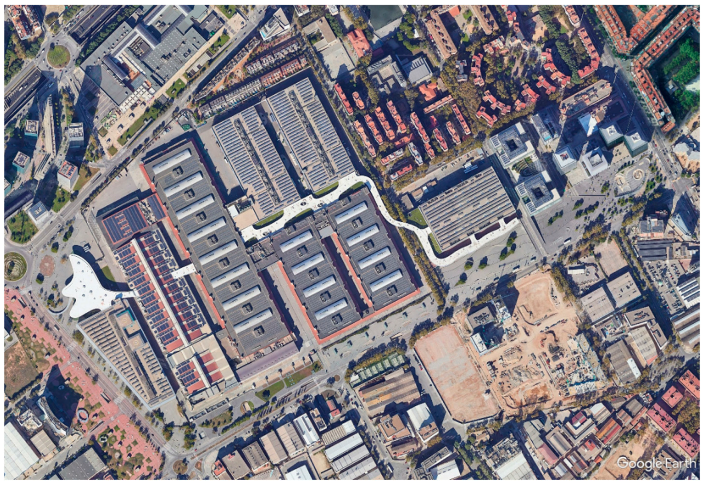
Figure 2.
Moment diagrams of a typical frame subjected to a uniform load of 37.5 kN/m. Top: continuous beam 45 + 13 + 45, with an absolute maximum moment of 564 kN·m. Bottom: simply supported beam with a span of 103 m, with an absolute maximum moment of 4,135 kN/m.
Figure 2.
Moment diagrams of a typical frame subjected to a uniform load of 37.5 kN/m. Top: continuous beam 45 + 13 + 45, with an absolute maximum moment of 564 kN·m. Bottom: simply supported beam with a span of 103 m, with an absolute maximum moment of 4,135 kN/m.
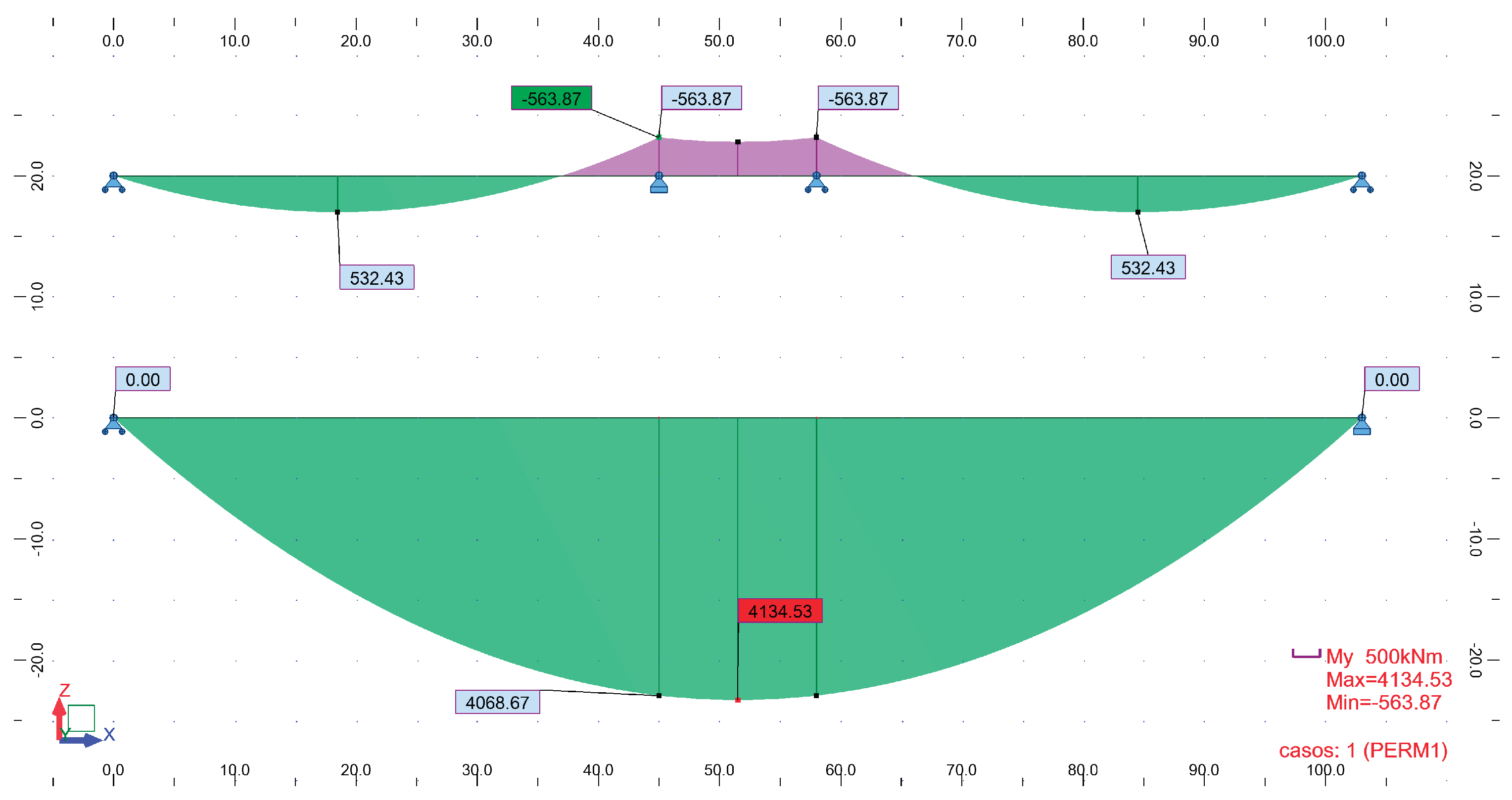
Figure 3.
Analysis of the proposal for the transverse frames: 11.8 m + 13 m + 11.8 m.
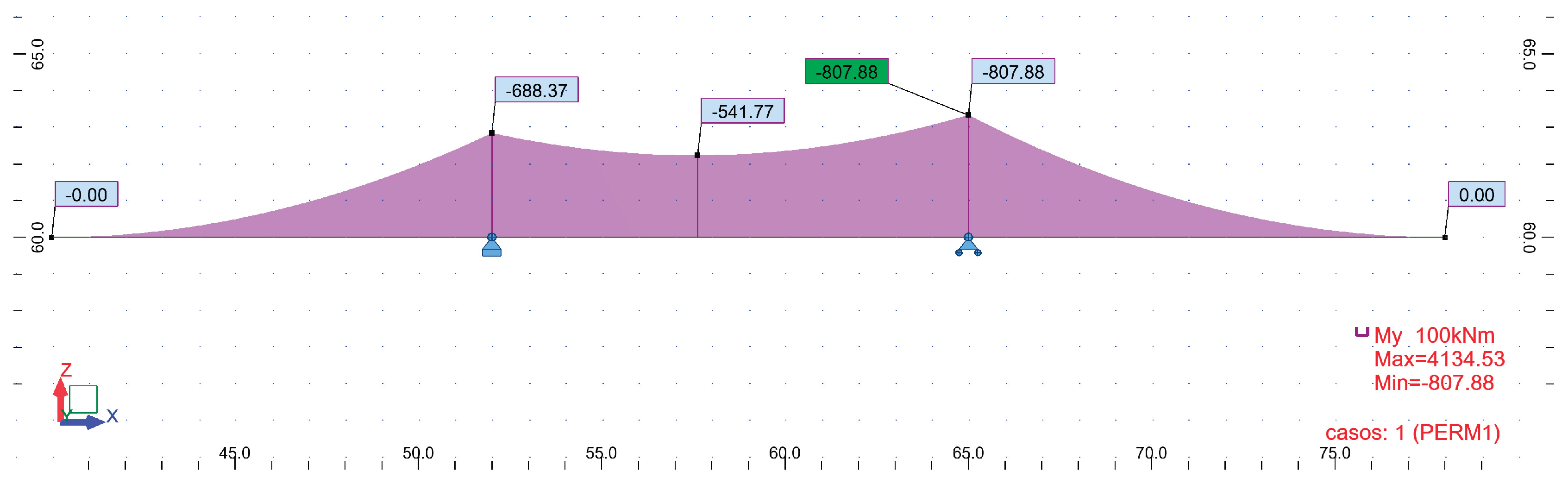
Figure 4.
Half-length frame defined in the final design phase. The image shows the variation in thickness of the diagonal members, depending on whether they are under tension or compression, and whether they are positioned at the ends or near the center of the span.
Figure 4.
Half-length frame defined in the final design phase. The image shows the variation in thickness of the diagonal members, depending on whether they are under tension or compression, and whether they are positioned at the ends or near the center of the span.
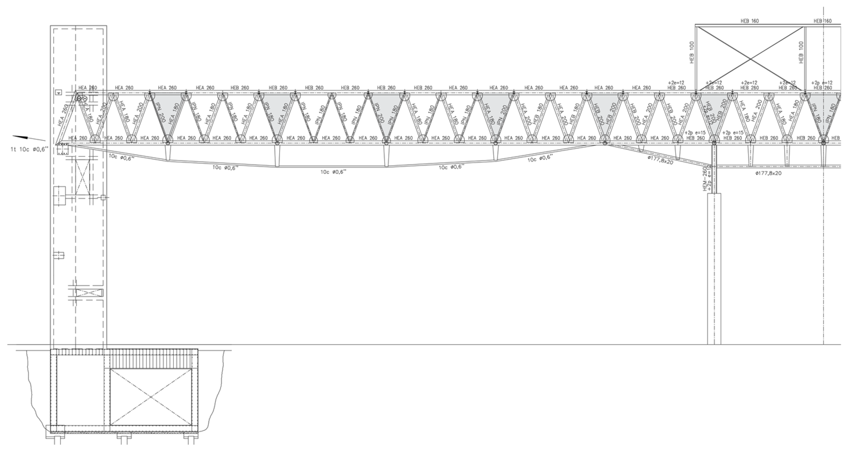
Figure 5.
Two adjacent longitudinal frames are shown in blue. The remaining elements correspond to two transverse frames, each 2.166 m wide and spaced 4.322 m apart. Each transverse frame is composed of two symmetrical cantilevers with variable sections and a central segment with a constant triangular section.
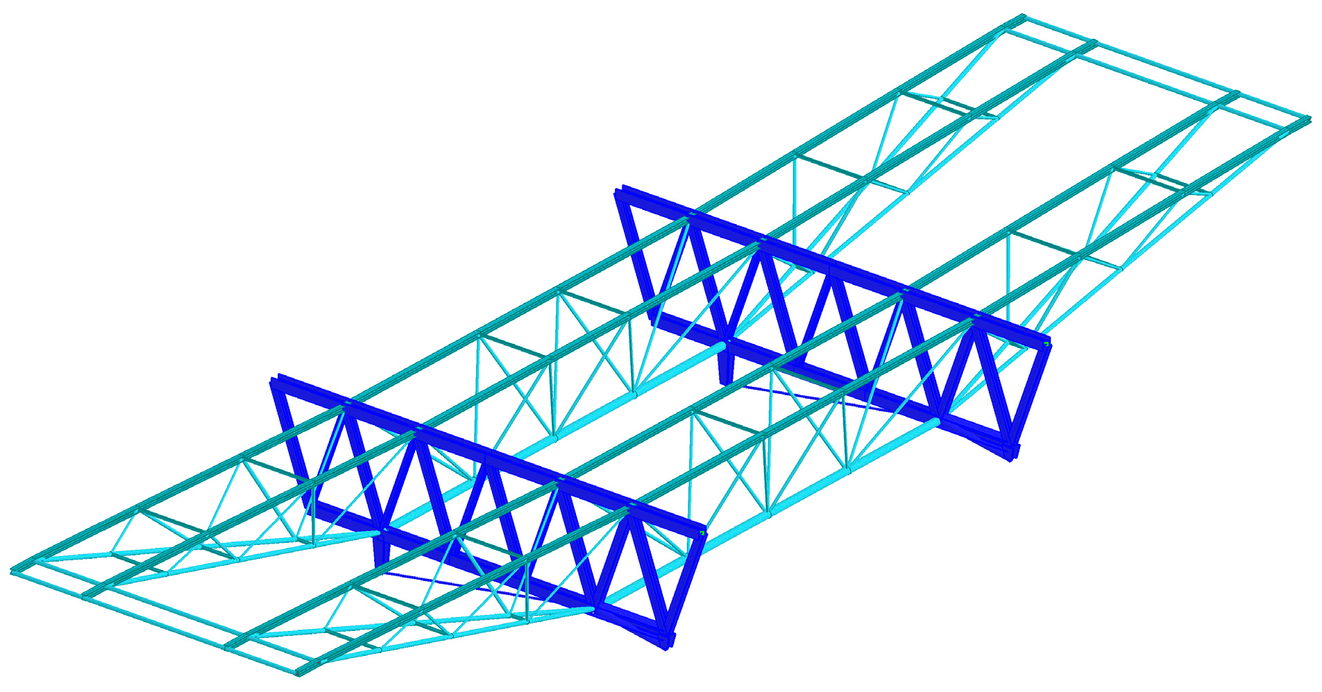
Figure 6.
Above, skylight solution. Below, reinforced raised beam at the expansion joint location.
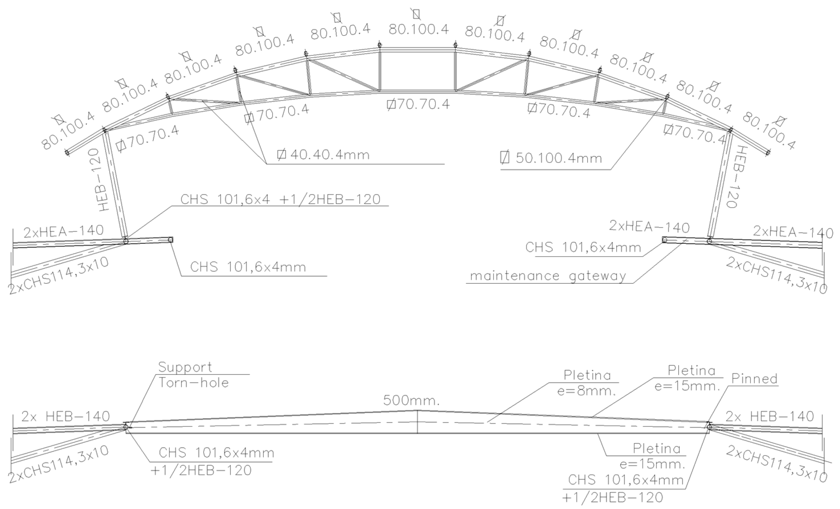
Figure 7.
Structure of the counterweighted façade beams in the final design. The central beam was originally intended as reinforced concrete, but on-site it was replaced with a steel beam, as explained in the following sections.
Figure 7.
Structure of the counterweighted façade beams in the final design. The central beam was originally intended as reinforced concrete, but on-site it was replaced with a steel beam, as explained in the following sections.
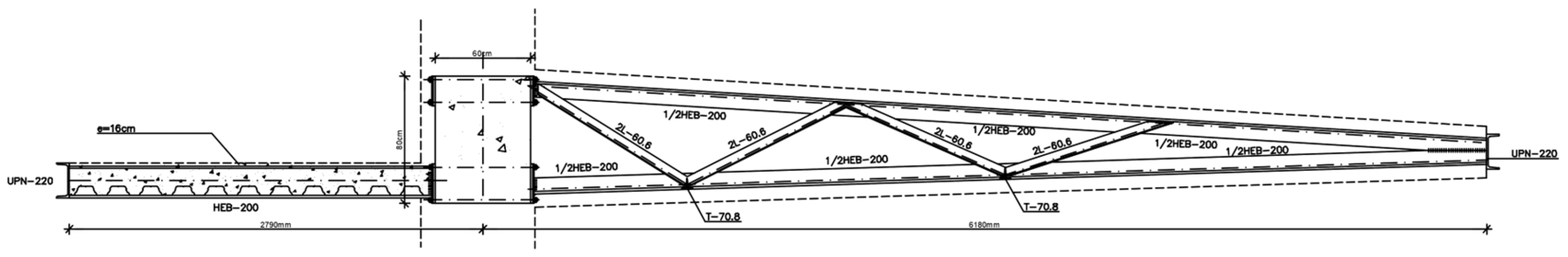
Figure 8.
Calculation model of Hall 3, initially generated in the Robot v6 program.
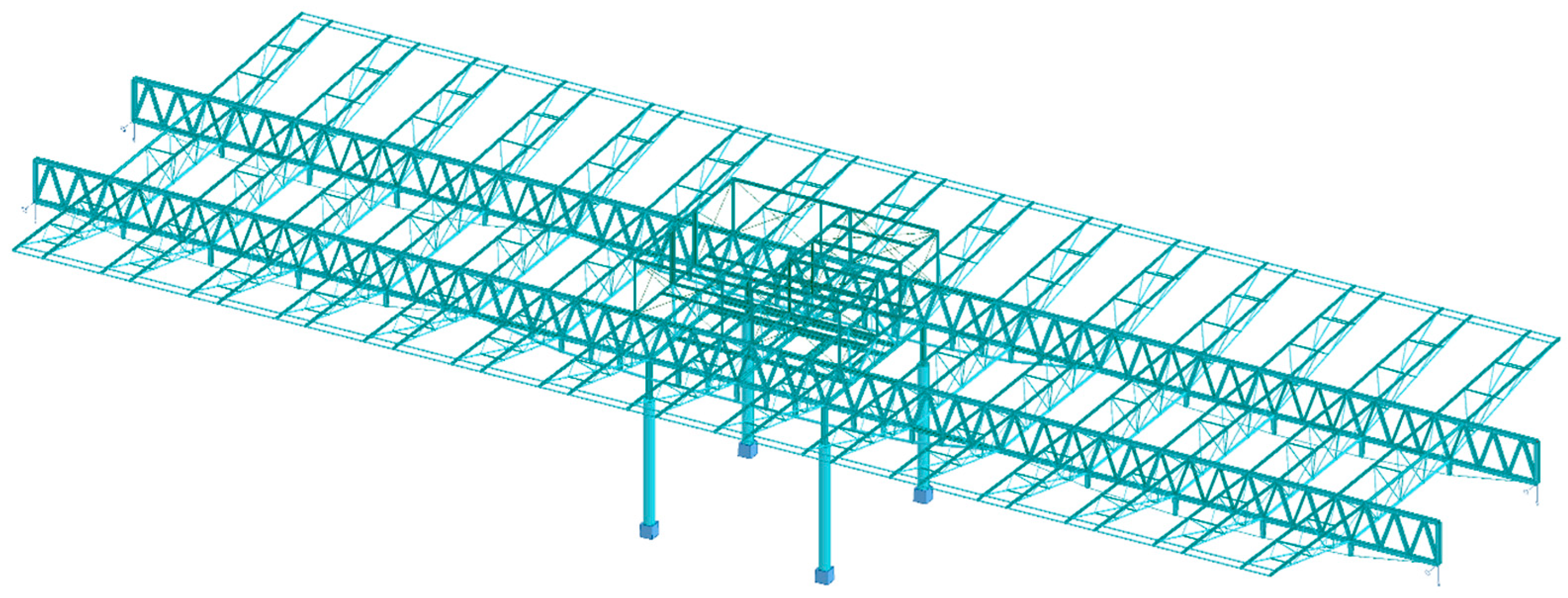
Figure 9.
Calculation model for the typical façade structure. Above, the wind-bracing beam acts as an expansion joint. At level 9.00, the counterbalanced cantilever. Below, the concrete pillars supporting the prefabricated panels, which are required to withstand R-90 fire.
Figure 9.
Calculation model for the typical façade structure. Above, the wind-bracing beam acts as an expansion joint. At level 9.00, the counterbalanced cantilever. Below, the concrete pillars supporting the prefabricated panels, which are required to withstand R-90 fire.
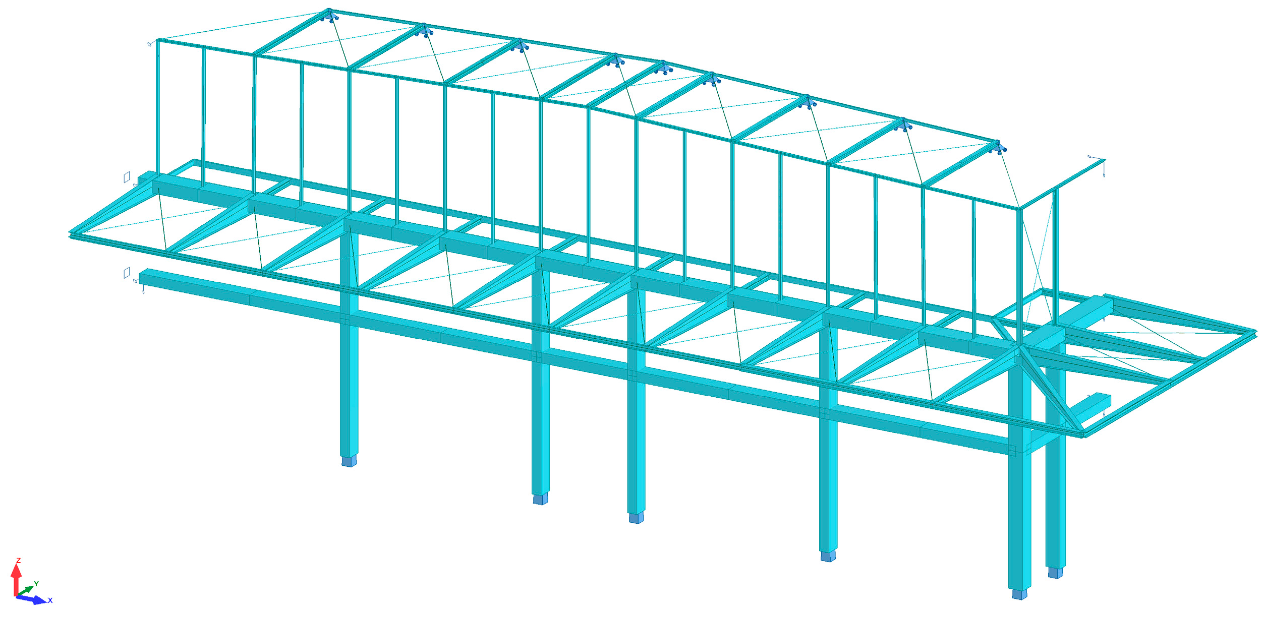
Figure 10.
Proposed continuity of a seamless building. The inclined pillars of each skylight are designed with low inertia in the illustrated plane, reducing stresses arising from different differential thermal expansions between members at different heights.
Figure 10.
Proposed continuity of a seamless building. The inclined pillars of each skylight are designed with low inertia in the illustrated plane, reducing stresses arising from different differential thermal expansions between members at different heights.
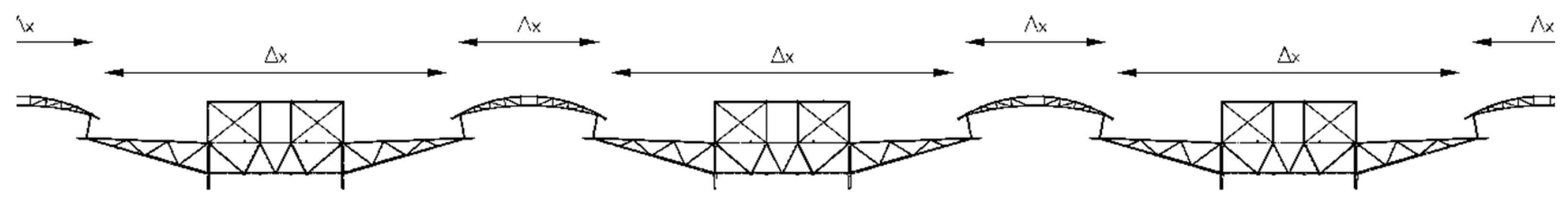
Figure 11.
The main metal structure of the hall, organized according to the parts defined in this article.
Figure 11.
The main metal structure of the hall, organized according to the parts defined in this article.
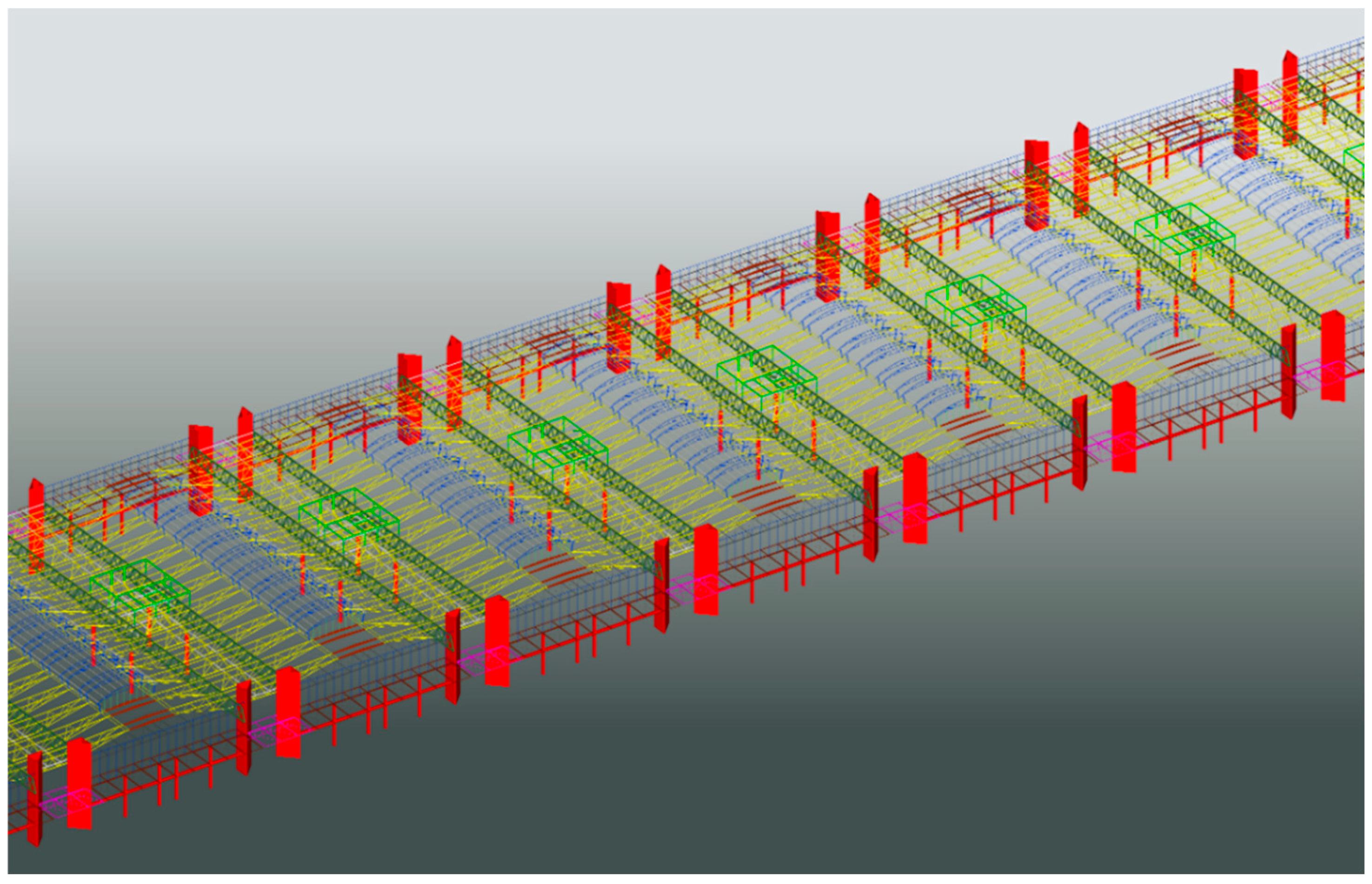
Figure 12.
Lifting of the central core of a typical module. The image shows two cranes performing the lift, and four mobile cranes, with four operators, securing each of the legs to the concrete pillars. In the background, a second module awaits lifting half an hour later. Up to five modules could be lifted in a single morning, optimizing the performance of the mobile cranes. Photograph by the author.
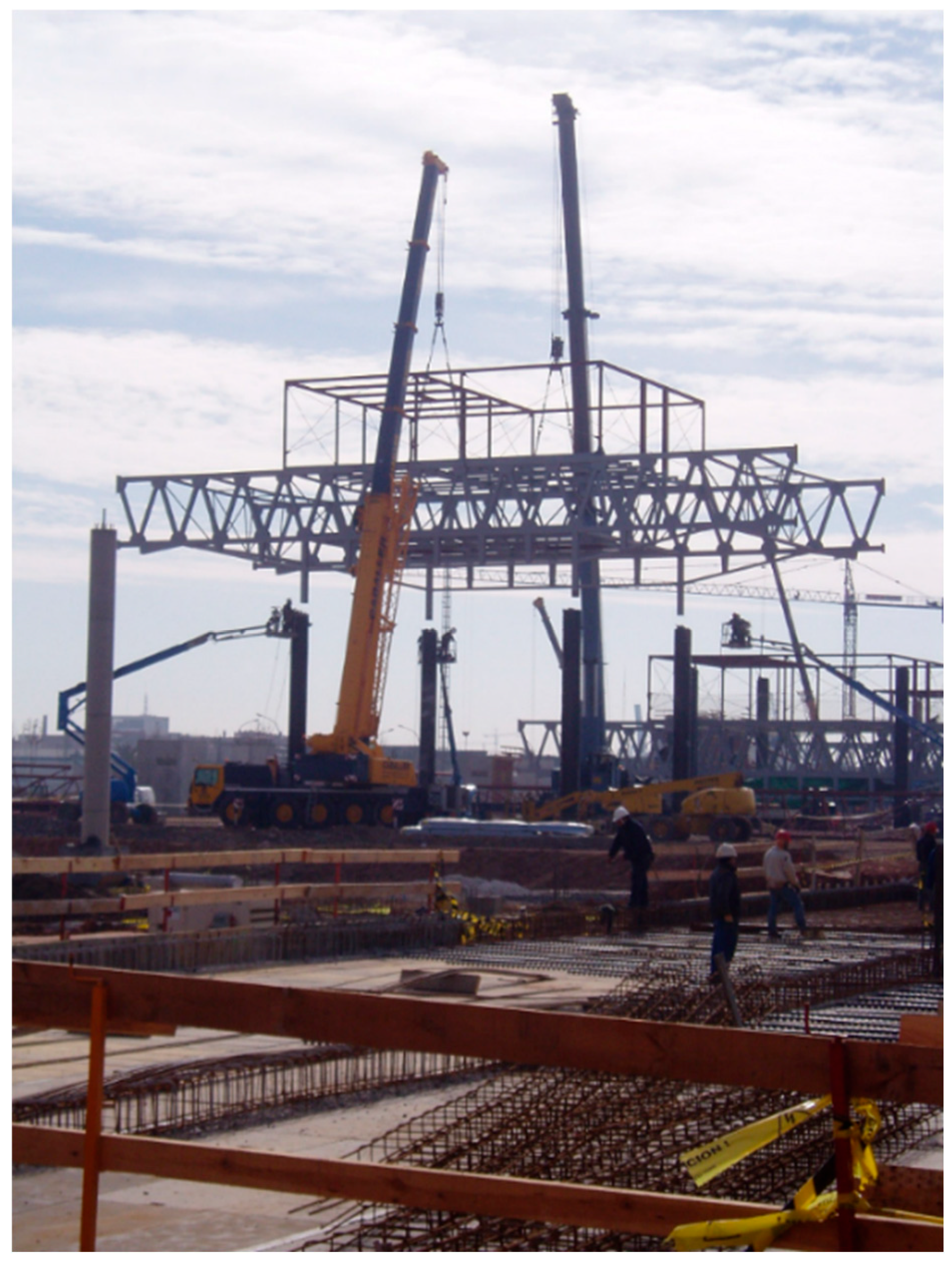
Figure 13.
Formwork closure process prior to concrete pouring. Due to the scale of the project, the entire operation had to be carried out using mobile cranes. Photograph by the author.
Figure 13.
Formwork closure process prior to concrete pouring. Due to the scale of the project, the entire operation had to be carried out using mobile cranes. Photograph by the author.
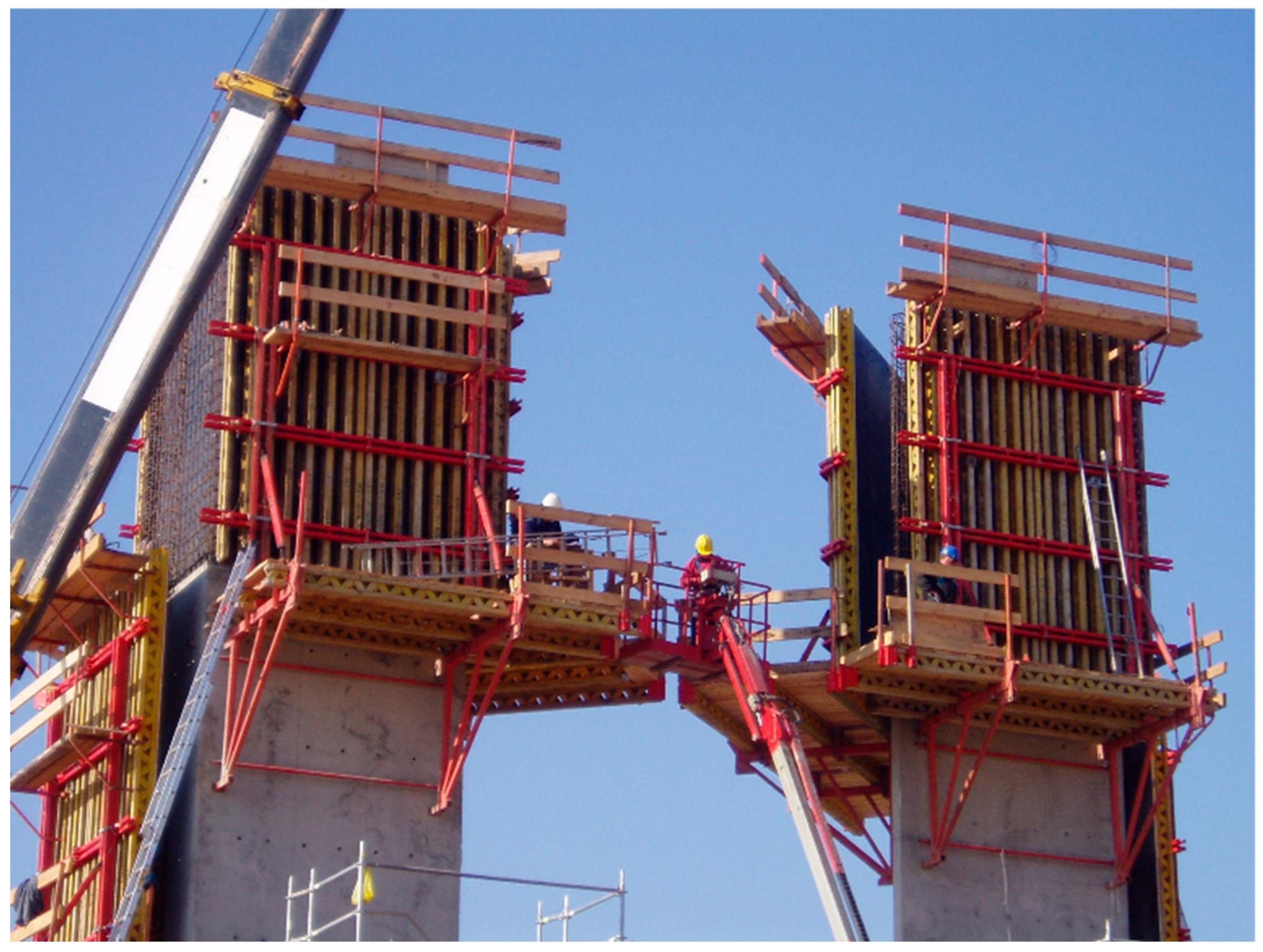
Figure 14.
View of the nearly completed two-module steel structure. Photograph by the author.
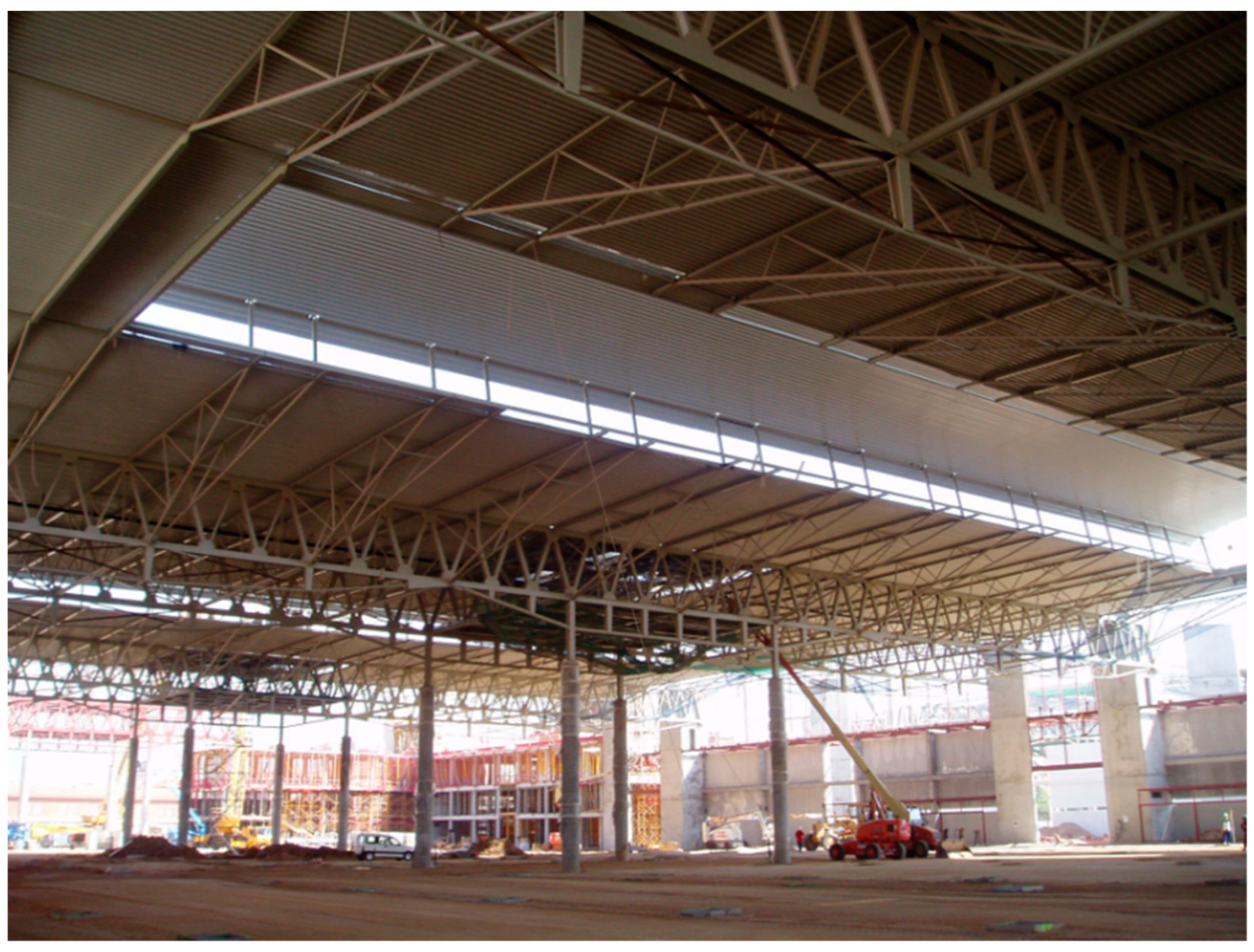
Figure 15.
Left (15.1), connection between the inner chord of the flat wind-bracing beam and the first transverse frame. Right (15.2), anchor plate between the ventilation core and the longitudinal frame.
Figure 15.
Left (15.1), connection between the inner chord of the flat wind-bracing beam and the first transverse frame. Right (15.2), anchor plate between the ventilation core and the longitudinal frame.
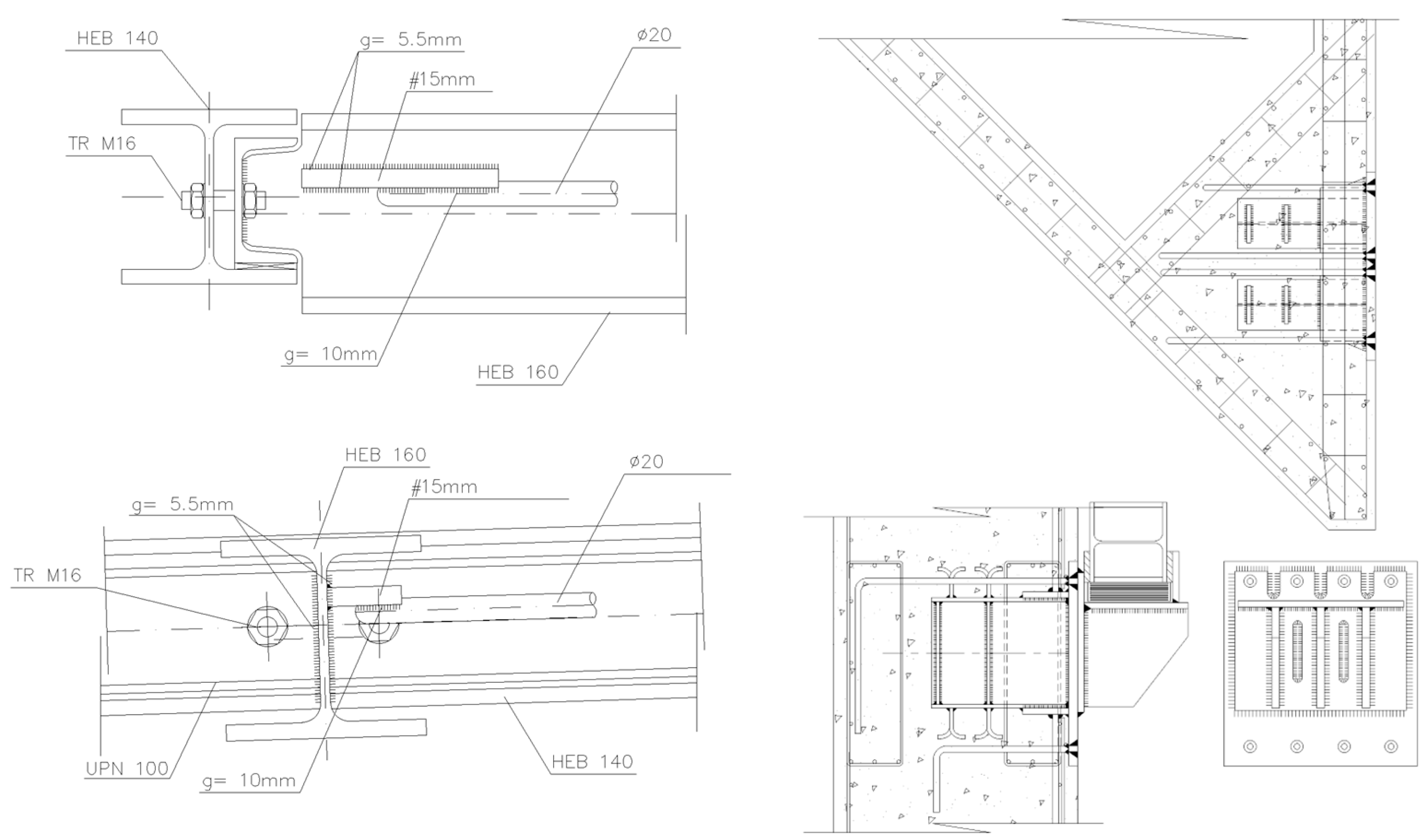
Figure 16.
Details of the knots illustrating all combinations between cords and diagonals.
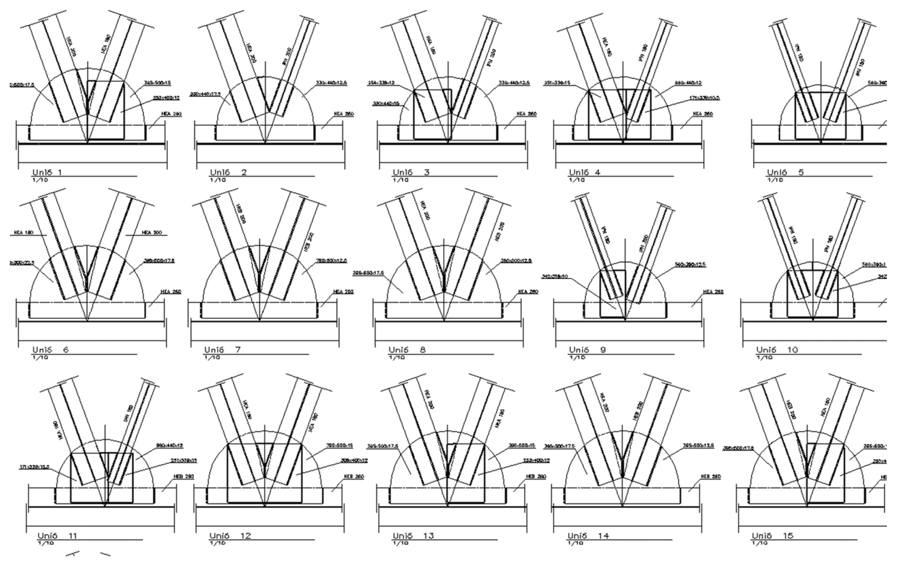
Figure 17.
Above, active detail, one on each façade. Below, passive detail, located approximately at L/3 and 2 L/3 along the longitudinal frame.
Figure 17.
Above, active detail, one on each façade. Below, passive detail, located approximately at L/3 and 2 L/3 along the longitudinal frame.
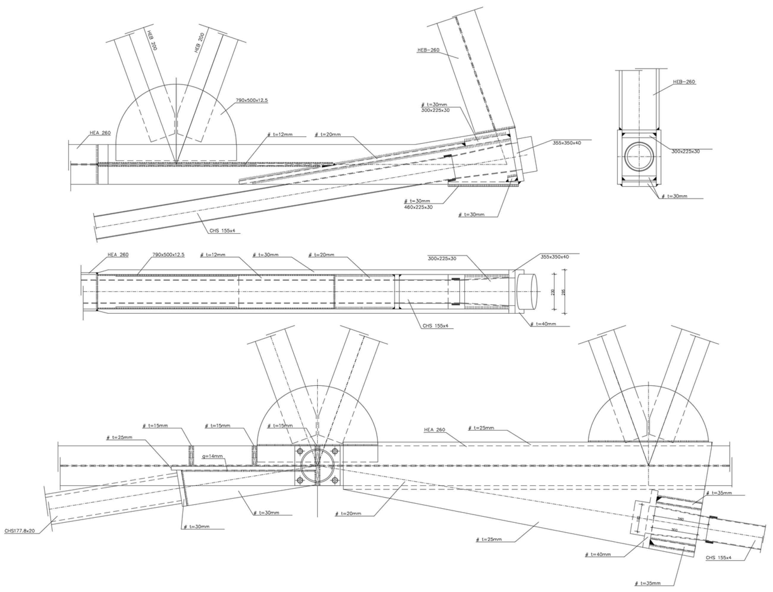
Figure 18.
Maximum stresses produced by the beam combined with the active forces. The right-hand plate, which contains a circular opening, experiences stress close to its elastic limit. A small internal reinforcement was added in this area, as shown in the section in Figure 17.
Figure 18.
Maximum stresses produced by the beam combined with the active forces. The right-hand plate, which contains a circular opening, experiences stress close to its elastic limit. A small internal reinforcement was added in this area, as shown in the section in Figure 17.
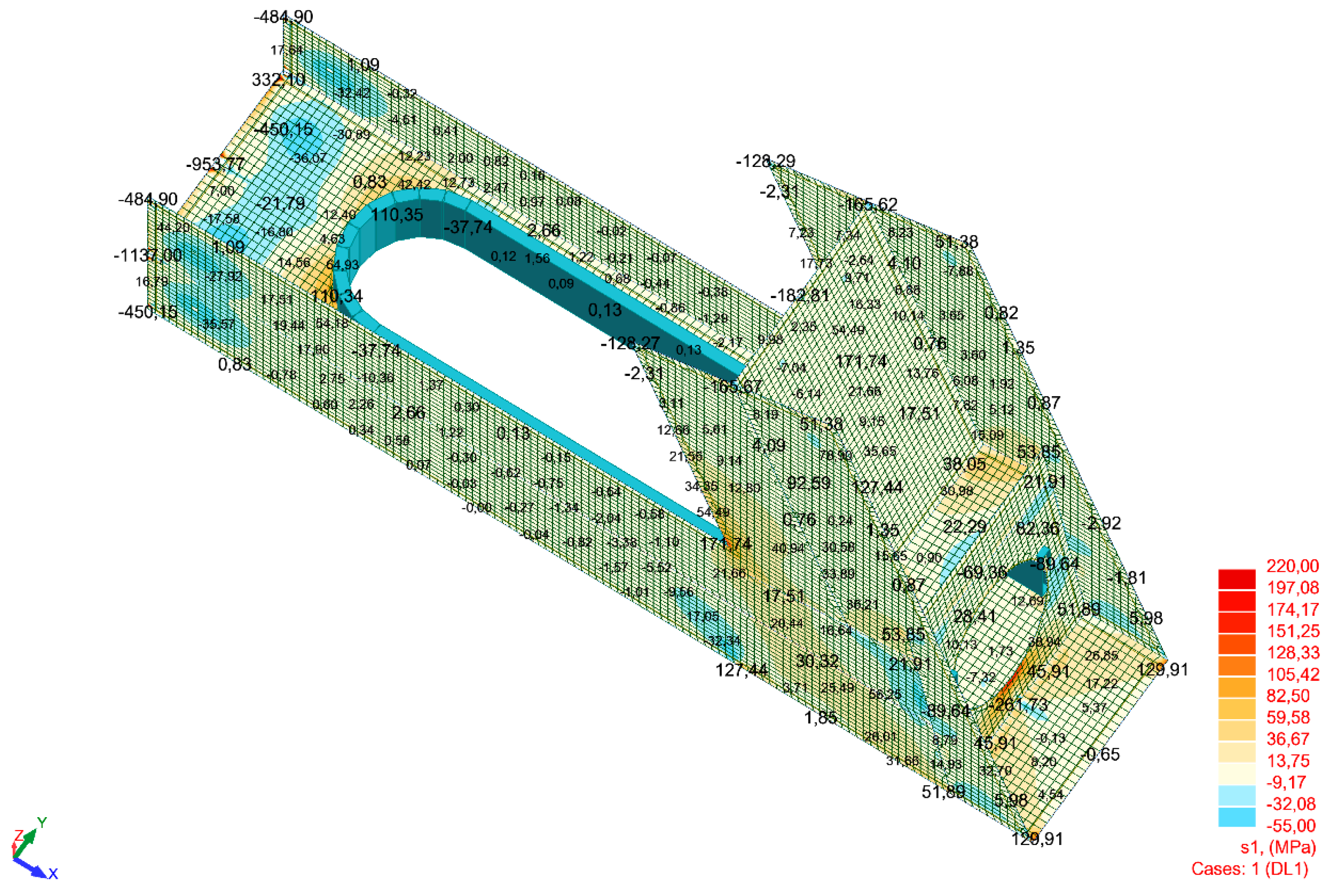
Figure 19.
Union of the prefabricated tube, formed from two 10mm sheets, to the ventilation core.
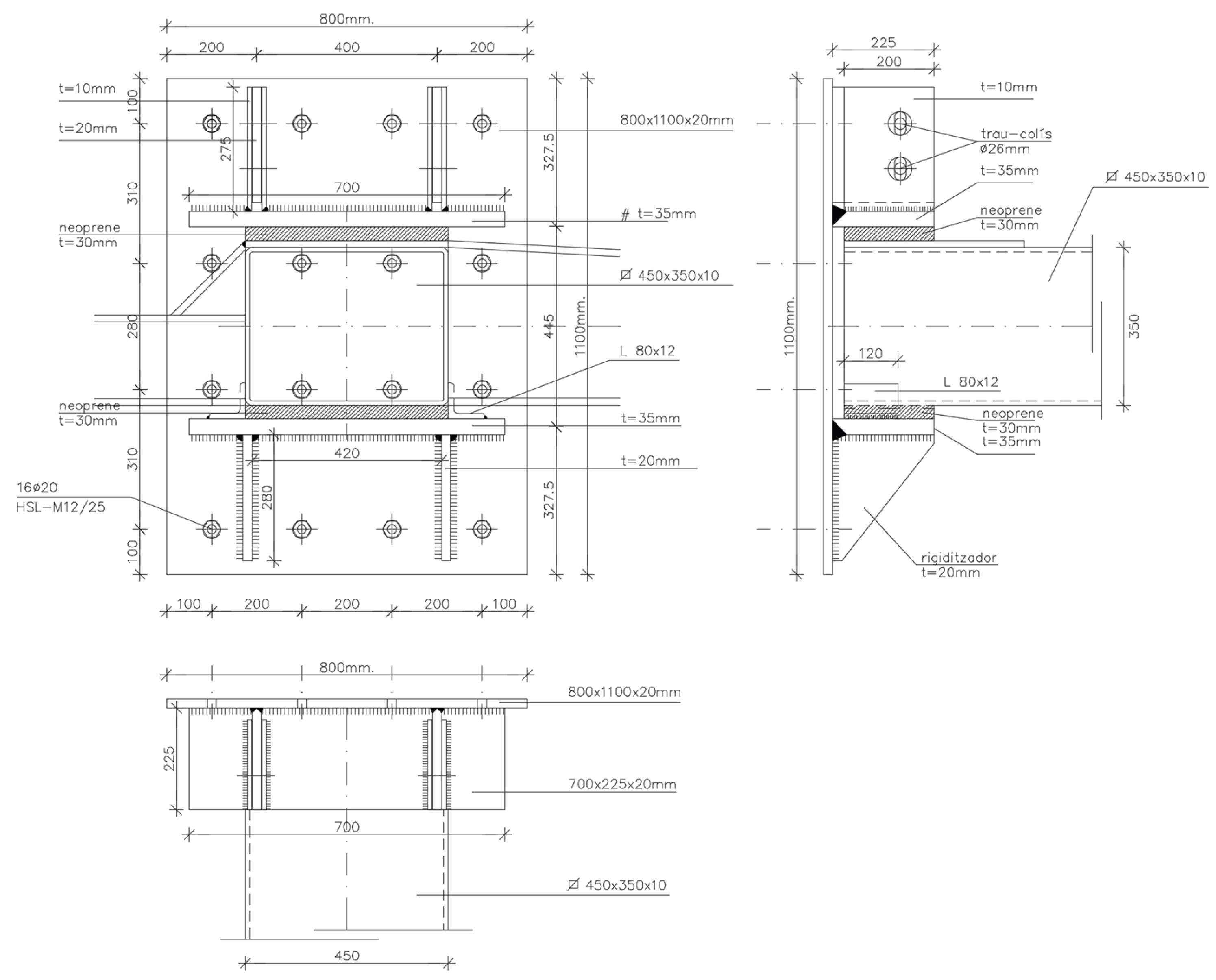

Table 1.
Structural comparison of the transverse frame between the two proposed solutions. The last column shows that substantial reductions in stress and the resulting cost savings.
Table 1.
Structural comparison of the transverse frame between the two proposed solutions. The last column shows that substantial reductions in stress and the resulting cost savings.
| Simply supported beam | Pinned-fixed beam | Difference | |
|---|---|---|---|
| Span (m) | 103 | 45 | |
| Uniform Load (kN/m²) | 1.00 | 1.00 | |
| Safety factor considered | 1.41 | 1.41 | |
| Distance between frames (m) | 1.00 | 1.00 | |
| Maximum Deflection (L/x) | 500 | 500 | |
| Bending moment formula used | =q·A.B.·L^2/8 | =q·A.B.·L^2/8 | |
| Bending moment (kNm) | 1,869.84 | 356.91 | 19% (-81%) |
| Minimum moment of inertia formula used | =5·q·A.B.·L^4/(384·E·L.D.) | =q·A.B.·L^4/(185·E·L.D.) | |
| Minimum Inertia (mm4) | 33,876,705,109 | 1,172,779,923 | 3% (-97%) |
| Approximate beam depth L/15 (m) | 6.87 | 3.00 | 44% (-66%) |
| 1 |
Disclaimer/Publisher’s Note: The statements, opinions and data contained in all publications are solely those of the individual author(s) and contributor(s) and not of MDPI and/or the editor(s). MDPI and/or the editor(s) disclaim responsibility for any injury to people or property resulting from any ideas, methods, instructions or products referred to in the content. |
© 2025 by the authors. Licensee MDPI, Basel, Switzerland. This article is an open access article distributed under the terms and conditions of the Creative Commons Attribution (CC BY) license (http://creativecommons.org/licenses/by/4.0/).
Copyright: This open access article is published under a Creative Commons CC BY 4.0 license, which permit the free download, distribution, and reuse, provided that the author and preprint are cited in any reuse.


