
Submitted:
03 November 2025
Posted:
04 November 2025
You are already at the latest version
Abstract
This overview is intended to shed light on the current state of knowledge on highly efficient cavitation reactors, which are used in industry yet often remain undisclosed. The development of ultrasound (US) and hydrodynamic cavitation (HC) reactors requires a thorough understanding and precise engineering to ensure the efficacy of cavitation processes in larger industrial settings. Successful scaling-up must maintain a high energy density and ensure a homogeneous distribution of cavitation. Industrial reactor designs for both US and HC are typically optimized for continuous flow operations, though some configurations operate in a loop system. This review provides a concise examination of various reactor setups, with examples of relevant chemical and environmental applications, focusing on energy consumption and scalability challenges. Despite the similarities in the effects of acoustic and hydrodynamic cavitation, US and HC are best regarded as complementary technologies in industrial applications. This work presents our direct experience in designing novel cavitation reactors for specific applications, incorporating recent advances from the literature and insights from industry. Notably, the synergistic effects of hybrid technologies are gaining attention, particularly the integration of HC with cold plasma, which is emerging as one of the most effective techniques for treating polluted water. These technologies play a crucial role in modern process engineering, and continued advancements in their design and understanding will further expand their industrial applications in chemical processing.
Keywords:
hydrodynamic cavitation
; reactor design
; flow-through reactor
; sonochemistry
; process intensification
1. Introduction
In 2006 the transfer of cavitational chemistry from research labs to large-scale applications was still a work in progress with few synthetic reports [1]. Even two decades later the discipline could not be regarded as mature, because if in one side ultrasonic activation was clearly generated by cavitational phenomena, the strict relationship to the equipment used strongly affected the reproducibility of the experiments [2].
Proper control of cavitation in larger reactors is critical to maintaining efficiency and preventing undesirable effects such as excessive heating and corrosion. Tailored designs are often required to meet the specific needs of different applications.
In the last few years, relevant reports have highlighted recent advances in sonochemistry, in particular sonocatalysis to carry out reactions under milder conditions while potentially improving selectivity and efficiency thanks to the positive interaction between solid catalysts and ultrasound [3]. The modelling of the acoustic cavitation field has evolved significantly and the main advances have been discussed by Tiong et al. [4]; however, further investigations are still ongoing to optimise sonochemical reactor designs and applications. New insights into acoustic cavitation modelling will facilitate the design and scalability of sonochemical systems. Analogue studies and surveys have shown the broad applicability of hydrodynamic cavitation in the selection of a suitable HC reactor design [5]. Process temperature, HC inlet pressure and cavitation number are crucial parameters, especially for the degradation of recalcitrant pollutants and the disinfection of harmful microorganisms. HC is becoming the best alternative technology due to its versatility and large-scale processability. The industrial use of HC was discussed by Meneguzzo and Zabini, who reported the production of almond milk and beer in a single operation with clear advantages [6]. Ciriminna et al. pointed out the need for commercial HC reactors for extraction processes [7]. Industrial sonochemical reactors were first developed in the 1960s by Saracco and Arzano, who described an optimised system for the hydrogenation of unsaturated oils. Their work showed that the reactor geometry has a significant influence on the reaction kinetics [8]. In the 1990s, great progress was made in the industrialisation of sonochemistry with the development of loop reactors (Harwell reactor), cylindrical tubular reactors and modular, series-connected units (Branson reactor) [9]. Large-scale reactors must be equipped with several ultrasonic transducers [10] designed as multistage systems consisting of several smaller ultrasonic units connected in series [11].
The scaling-up of sonochemical batch reactors suffers from the limited penetration depth of ultrasonic waves into the liquid. For this reason, several industrial applications have been developed in flow-through reactors. Scaling laws are used to establish the relationship between reactor size and the power necessary to achieve and sustain cavitation [12].Maintaining appropriate power density across larger reactors is vital to achieving the desired cavitation effects [13].The design and geometry of cavitation reactors must be optimized for larger scales. This includes considerations such as the shape of the reactor chamber, the arrangement of cavitating elements (e.g., ultrasonic horns or transducers), overall flow dynamics [14] and the eventual combination of different frequencies [15].
The primary industrial applications of cavitation technology include water treatment where it enhances pollutant degradation and microbial inactivation, emulsification which improves the stability and uniformity of emulsions, heterogeneous catalysis by effectively cleaning and regenerating catalyst surfaces to maintain efficiency, and sonocrystallisation which promotes controlled nucleation and crystal growth, leading to improved product quality and yield.
Solid/liquid extraction is typically a batch process, and a new paradigm is a flow-through procedure with a multi-horn or multi-transducer flow reactor [16,17], also for semi-industrial biomass delignification [18]. Scaling up also introduces challenges in selecting reactor materials, which must withstand increased stresses and pressures associated with larger volumes and higher power levels. Material compatibility with the cavitation process, resistance to erosion, and durability become critical factors. Larger reactors may generate more heat due to higher power inputs, necessitating the incorporation of efficient heat dissipation mechanisms to prevent overheating and maintain optimal operating conditions. The successful experience in the extraction of extra-virgin olive oil assisted by ultrasound showed that commercial square-shaped tubular reactors were not suitable because the irregular waves transmission with consequent heat generation. Differently a correct reactor design with a round shape drastically minimizes heat generation [19]. Energy efficiency at larger scales is another key concern in achieving the goal of process intensification [20]. In terms of energy consumption, HC is generally more favourable than ultrasound. The latter can be based on a horn-type system or a multiple transducer. Acoustic cavitation with horns struggles to efficiently convert acoustic energy throughout a large fluid volume because the intensity of cavitation decreases exponentially with distance from the tip of the horn, becoming negligible at relatively short distances. In contrast, while using multiple transducers results in lower operating intensities for the same power dissipation levels, the new generation of reactors described in paragraph 5 allows for highly efficient flow-through chemical processes. Recent literature confirms the advantages of flow-through cavitation reactors [21]. Starting from studies on sono-microreactors, the development of mesoscale and pilot scale systems could be successfully applied in the production of nanoparticles and also the degradation of pollutants in wastewater. Strategies to optimize energy transfer, minimize losses, and enhance overall reactor performance remain active areas of research and development. A notable example of a flow-through industrial application of ultrasound is sonocrystallization, which ensures faster nucleation kinetics, reduces crystallization time, and promotes uniform crystal morphologies with controlled particle size distribution. In particular, the crystallization of active pharmaceutical ingredients (APIs) helps prevent undesired polymorphs and ensures consistency in pharmaceutical formulations [22]. The engineering development of new industrial plants incorporating cavitation reactors is often led by manufacturers, who rarely rely on dedicated academic studies for support. Large-scale reactor development is primarily industry-driven, with academic research mainly focused on fundamental aspects. The equipment must be robust enough to withstand long operating hours, minimizing corrosion phenomena while ensuring ease of maintenance. In the following paragraphs, we describe various types of cavitation reactors that can be scaled up for pilot- or large-scale applications.
2. Hydrodynamic Cavitation
Hydrodynamic cavitation reactors (HCRs) are continuous-flow devices designed to generate cavitation. Unlike acoustic cavitation, which relies on low-frequency ultrasound to create a low static pressure region in the medium, in HC, the velocity of the fluid is altered to create low static pressure regions. HCRs have been widely used in various applications, including wastewater treatment, biodiesel synthesis, and water disinfection, among others [23]. Based on the operating characteristics of the device, HCRs can be broadly classified into two types: 1) devices with moving parts and 2) devices without moving parts [23]. Besides the geometric parameters, material properties and operating conditions also play significant roles in affecting cavitation in HCRs. The schematic of different devices is shown in Figure 1.Cavitation in HCRs is characterized by a dimensionless parameter known as the cavitation number (), which is defined in the following Equation 1
– Pressure downstream of the device
– Vapour pressure of the liquid at the bulk-liquid temperature
– Density of the fluid at the bulk temperature
- Velocity of the fluid at the device inlet
A is considered optimal for the generation of cavitation. Lower values of result in increased cavitation intensity.
The design and operational parameters of devices without moving parts, such as orifices, venturi, vortex diodes, and venturi orifices with swirlers, will be discussed in detail.
2.1. Devices Without Moving Parts
2.1.1. Orifice Devices
Orifice devices consist of a plate with dimensions different from those of the inlet flow channel. As fluid flows through the orifice plate, its velocity increases, resulting in a reduction in local static pressure, which subsequently induces cavitation [24]. The performance of these reactors is influenced by their geometrical characteristics, namely size, shape, and number of holes in the orifice (Figure 2). Reducing the size of the holes increases fluid velocity, thereby increasing cavitation intensity. Hole shapes, such as rectangular or elliptical, can also contribute to the cavitation. In the case of multiple-hole orifices, a large number of small holes is more effective than an orifice with a single hole [23], as shown in textile dye degradation [25]. The orifice reactors have a growing industrial application for wastewater treatment and the degradation of organic pollutants [26].
Relevant factors are α and β (Equations 2 and 3), that are discussed in detail below.
This parameter is influenced by the size, shape, and number of holes in the orifice. Reducing the size of the holes increases fluid velocity, thereby increasing cavitation intensity. Hole shapes, such as rectangular or elliptical, can also contribute to higher α values [23].
For multiple hole orifices, a large number of small holes is more effective than a single hole orifice. Higher α values slow the recovery of downstream pressure within the device, resulting in a reduction in collapse pressure.
As the value of β increases, the higher throat velocity in the fluid leads to an increase in the collapse pressure of cavities, resulting in more intense cavitation.
α is directly proportional to the number of holes in the orifice and inversely proportional to the size of the holes in the multiple hole orifice plate. β values influence the diameter of the orifice hole with respect to the cross-sectional area of the pipe [27]. The factors α and β, which depends on the number of holes and diameter of holes directly affects the number of cavities generated and intensity of cavity collapse respectively. Increasing the α increases the number of cavity generation sites and in contrast decreasing the β, increases the velocity and thereby reduces the cavitation number given by (Equation1) increasing cavitation.
The optimal values of α and β must be determined based on specific application. While an increase in α generates a greater number of cavities, it also leads to a decrease in the intensity of cavity collapse. Conversely, an increase in β increases the collapse pressure of the cavities but reduces the number of cavities generated [28]. The selection of α and β values should align with the application’s requirements, whether it demands more intense cavity collapse with fewer cavities or a larger number of cavities with less intense collapse.
Other operational parameters, such as temperature and inlet pressure, significantly influence the cavitational yield. Increasing the inlet pressure enhances the intensity of cavitation up to a critical cavitation number. However, higher inlet pressure also raises the recovered downstream pressure, intensifying cavity collapse but reducing the number of cavities generated [28]. To optimise cavitational performance, an appropriate inlet pressure must be maintained to maximise cavity collapse without drastically lowering the number of cavities generated.
2.1.2. Venturi Devices
Venturi devices consist of a convergent section, a throat, and a divergent section. Unlike an orifice device, the velocity and pressure change gradually in a venturi device (Figure 2). This gradual change in velocity and pressure allows the cavities to grow to a significant size and enables the bubbles to remain in the low-pressure region for a longer duration [27]. Similar to orifice devices, venturi devices are also affected by geometrical factors such as γ (Equation 4) and the divergence angle of the divergent section, as well as operating parameters like temperature and inlet pressure.
Cavitation number increases with a longer throat length and decreases with a larger throat diameter. An increase in throat length increases friction, leading to the formation of inactive bubbles that dissolve into the surrounding liquid without collapsing. The value of γ affects the residence time of the cavities, which determines the maximum size the cavities can reach, and, consequently, influences the cavitation intensity. Numerical studies have shown that an optimal γ value of 1:1 yields the best performance.
If the cross-sectional area is considered constant, a larger throat perimeter increases the number of cavities generated. Throat geometries such as rectangular, slit, and elliptical provide better cavitation performance than circular throats. The cavitation number increases with a longer throat length and decreases with a larger throat diameter. An increase in throat length increases friction, leading to the formation of inactive bubbles that dissolve into the surrounding liquid without collapsing [28]. The divergence angle is critical in the recovery of pressure downstream of the venturi device, influencing both the collapse pressure and cavitation yield. Higher divergence angles increase the cavitation number and reduce collapse intensity. Numerical studies have shown that a divergence angle of 5.5ο is optimal [29]. Reducing the outlet divergence angle is an effective way to generate more microbubbles and increase cavitation yield by raising the collapse pressure of the bubbles.
Other operational parameters, such as temperature and inlet pressure, significantly influence the cavitation yield. Increasing the inlet pressure enhances the intensity of cavitation up to a critical cavitation number. However, higher inlet pressure also raises the recovered downstream pressure, intensifying cavity collapse but reducing the number of cavities generated [29]. To optimise cavitation performance, an appropriate inlet pressure must be maintained to maximise cavity collapse without drastically lowering the number of cavities generated. An increase in temperature raises the vapour pressure, causing cavitation to initiate earlier. It also reduces gas solubility, affecting the number of nuclei available for cavitation. Higher temperatures, however, lead to a decrease in collapse pressure, thereby reducing cavitation intensity. These reactors have proved to be useful in the removal of API molecules such as Sulfamerazine on a pilot scale, and it is concluded that design parameters play a crucial role in comparing different internal structures [30]. Emulsification of oil-in-water was performed using the slit venturi reactor, which shows a higher size reduction of the oil phase in comparison to circular venturi per pass [31]. The sterilization effect of cavitation was studied using a venturi reactor, and geometrical parameters were optimised to increase the killing rate of E. coli [32].
2.1.3. Vortex Diode
A vortex diode is a disc-shaped device with cylindrical axial and tangential ports (Figure 2). The axial port comprises a diffuser section, an expander, and a straight section. Both the axial and tangential ports have the same divergence angle. When fluid flows in the reverse direction, from the tangential port to the axial port, it generates a vortex, increasing fluid velocity and causing a significant pressure drop, which leads to cavitation [33]. The performance of the vortex diode is evaluated using a parameter known as diodicity (D) given by Eq. (5). The design of the vortex diode is affected by several factors, including diode geometry, size, aspect ratio, nozzle configuration, and the Reynolds number. Devices with higher diodicity provide better performance (5).
- Reverse flow pressure drop
- Forward flow pressure drop
Diodicity is affected by the flow rate of the fluid in the vortex diode, which is characterised by the dimensionless Reynolds number (Re), and for a vortex diode it is given by Eq. (6).
ρ– Density of the fluid
– Velocity of the fluid in nozzle
Diameter of the inlet nozzle
µ - Dynamic viscosity of the fluid
The aspect ratio () of the vortex diode is given by Eq. (7):
dv- Diameter of the chamber
hv- Height of the chamber
The aspect ratio affects the strength of the vortex formed in the diode chamber. In the absence of wall friction, increases in the aspect ratio led to higher diodicity. The optimal aspect ratio varies with Reynolds number [34]; for the highest Reynolds number flow in the diode, the optimum aspect ratio was found to be 6. However, the increase in diodicity with respect to Reynolds number seems to plateau after a certain value. The divergence angle of the tangential and axial ports to the diode plays a crucial role in vortex strength. Increasing the divergence angle from 5ο to 7 ο enhances the diodicity of the diode [29]. Nozzles with an inlet diameter equal to the height of the diode, attached to both the tangential and axial portions, result in higher diodicity. Moreover, the radius of curvature of the expander section of the nozzle influences diodicity. A larger radius of curvature increases the pressure drop for forward flow, which in turn reduces the diodicity of the diode [33]. The throat diameter of the device can be adjusted while keeping the device diameter constant. This modification shows that the maximum tangential velocity increases with an increase in throat diameter up to a scaling factor of 4, after which it levels off. The frequency of fluctuation decreases with scale, which impacts the cavity dynamics. Vortex diode devices have the potential for removal of antibiotics, organic pollutants and also in sterilization of water. The vortex diode is used for disinfecting both gram positive and gram negative and shows greater efficacy in comparison to an orifice device. The pilot scale study for removal of ciprofloxacin and metformin using the device showed that along with hydrodynamic cavitation incorporating oxidising agents such as hydrogen peroxide showed a significant effect on the removal of the contaminants owing to the complex structure of the molecule [35,36]. Vortex diodes show better performance in degradation of API pollutant Naproxen in comparison to the orifice device [37].
2.1.4. Venturi and Orifice with Swirler
Venturi and orifice devices are equipped with a swirler in the flow path to shift the cavitation zone away from the wall and into the core of the fluid flow. The presence of the swirler influences cavitation inception, pressure drop, and the flow characteristics. The parameters affected by the swirler lead to changes in turbulent fluctuations, which in turn affect cavity dynamics. The performance of the venturi and orifice devices with a swirler is influenced by the swirl ratio and Reynolds number [38]. The Swirl ratio is defined by Eq. (8):
uθmax -Maximum tangential velocity
-Mass average velocity at throat
The pressure drop increases with velocity. However, the pressure drop for an orifice and venturi device with a swirler is lower than that in the same devices without a swirler. Cavitation inception occurs at a lower pressure drop for orifice and venturi devices with a swirler compared to those without one [38]. The difference in pressure drop at cavitation inception is 10 kPa for the orifice and 5 kPa for the venturi, both with and without a swirler, respectively.
The presence of a swirler in orifice and venturi devices significantly affects flow characteristics. In an orifice without a swirler, the cavitation zone remains near the throat, and only after a certain higher pressure drop do cavity clouds break into fine bubbles [38]. However, in an orifice device with a swirler, the cavitating vapour region in the throat collapses and forms cavity clouds downstream of the device. In a venturi device without a swirler, vapour clouds form at the edge of the throat and move along the diffuser, where they break into smaller vapour clouds. These smaller clouds then move back toward the throat, restarting the process. In contrast, in a venturi device with a swirler, the vapour clouds extend along the axis of the diffuser, and the swirl tends to dampen the axial advance and retreat of the cavity bubbles.
For venturi and orifice devices with a swirler, the pressure drop is lower than that of the same devices without a swirler, up to a swirl ratio (S) of 2. However, for a swirl ratio greater than 2, both devices with a swirler show an increase in pressure drop compared to those without a swirler [38]. Devices with a swirler demonstrate a monotonic increase in pressure drop at a swirl ratio of 8 or higher, leading to increased turbulent fluctuations, which, in turn, affect cavity dynamics.
2.2. Devices with Moving Parts
Rotational hydrodynamic cavitation reactors (RHCRs) are a class of reactors that increase tangential velocity by accelerating the fluid and forcing it to flow through varying cross-sections to create the pressure differentials necessary for cavitation. RHCRs can be classified as rotor-rotor or rotor-stator devices, depending on the mechanics of the device. The key factors affecting the performance of RHCRs include flow rate, rotational speed, pressure within the device, and the design of the rotor. In RHCRs, increases in rotational speed led to higher tangential fluid velocity, resulting in higher turbulence intensity and increased cavitation intensity. To achieve maximum cavitation intensity, the axial gap between the plates should be minimised [39]. Additionally, increases in temperature enhance cavitation intensity up to a certain point [40]. Serrated rotary disc HC generators are rotor-rotor devices in which the design of the disc is crucial for efficient cavity generation. Compared to discs with grooves that are at right angles to each other, discs with grooves inclined at an 8ο angle offer better performance [41]. In this design, the groove functions as a venturi, aiding in the distribution of the cavitation cloud.
A pinned disc HC generator is a rotor-stator device where cavitation is generated by a sudden pressure drop and its subsequent recovery downstream of cylindrical pins caused by flow acceleration and separation. Reducing the inlet pressure by adjusting the flow rate increases the cavitation volume fraction but reduces the overall cavitation effect. Advanced rotating HC generators, which are rotor-stator devices, consist of rotating discs with dimples on the disc edges. The pressure amplitude increases as the distance between the plates is reduced. Both vortex cavitation and sheet cavitation have been observed in the system; sheet cavitation occurs in the space between the rotor and stator, while vortex cavitation is predominantly observed in the Cavitation Generation Unit (CGU) [42]. Since both vortex intensity and flow separation occur during the interaction process, the shape, geometrical factors, and arrangement of the CGU should be optimised for improved performance.
Rotor/stator HC units are widely used in industrial applications, particularly for oxidative polymerization and emulsification of oils. These processes benefit from the generator’s low energy consumption, making them highly scalable. The production of fat liquors from waste frying oils is a process with significant industrial impact across various applications [43]. Even more commonly, rotor/stator generators are used in biodiesel production [44] and in the pretreatment of the organic fraction of municipal solid waste to enhance anaerobic digestion [45].
Challenges for scale up of hydrodynamic cavitation reactors can be summarised as follows. The geometrical parameters play a crucial role in scale up of hydrodynamic cavitation reactors in comparison to the process parameters. Process parameters are system dependent, and it is affected by several factors like temperature, inlet pressure, initial cavity radius. The geometrical and process parameters are optimised for scale up depending on the application (Table 1).
In hydrodynamic cavitation reactors, the cavity collapse pressure is strongly influenced by reactor design parameters [46]. For orifice systems, β plays a critical role, as changing β independently alters other geometrical factors such as the L/D ratio, which in turn affects cavitation inception and flow characteristics [47]. Moreover, β directly impacts the cavitation number, which must be minimized to achieve cavitation effects comparable to those observed in smaller-scale systems [48].
In venturi reactors, the parameter γ plays a crucial role in scale-up, as altering it independently changes the converging and diverging angles of the venturi tube [49]. An increase in γ raises frictional losses, reducing cavitation efficiency, while modifications in the divergence angle directly influence pressure recovery, thereby significantly impacting cavity dynamics [27].
In a vortex diode, variation in throat diameter significantly influences flow characteristics, with the maximum tangential velocity increasing only up to about twice the smallest throat diameter, beyond which it plateaus [34]. This change in cross-sectional area not only governs the maximum velocity attainable but also impacts the formation and behaviour of the vapor core in the axial port [34]. Furthermore, scaling up alters the eddy frequency within the device, while dimensional modifications directly affect the overall design considerations required to achieve maximum efficiency.
In a rotational cavitation device, the diameter and design of the rotating element govern the maximum tangential velocity and local velocity profile, which in turn influence vapor formation [50]. The blade spacing and rotational speed set the limits on fluid throughput and reactor pressure, thereby controlling both the processable volume and the intensity of cavity collapse.
Process parameters like inlet pressure, temperature, initial cavity radius, pH, and additive concentration are system-specific and cannot be generalized, requiring optimization on a case-by-case basis to achieve optimum results as detailed in the previous sections.
Scale-up of cavitation systems is inherently nonlinear due to the complexity of the multiphase phenomena, and no single parameter can be adjusted independently to ensure success. Comparable efficiency is often achievable only within certain scale-up ratios, beyond which performance declines [34].
To address this, tools such as computational fluid dynamics and simulations are essential for understanding system intricacies, while a hybrid approach combining numbering-up with scale-up offers a practical route to larger scales without compromising efficiency [51].
3. Ultrasonic Reactors for Semi-Industrial Applications: Flow-Through Units
Recently Tiwari and associates reported challenges and strategies for scaling up ultrasonic rectors [52] showing that the ultrasonic energy transferred to the bulk is crucial in most processes. Parameters such as US power (W), US intensity (W/cm²), and acoustic energy density (W/mL) quantify the dissipated ultrasonic energy in the system.
The main concepts and parameters to consider when scaling up ultrasonic reactors are summarised in the table below.

Table 2.
Relevant parameters to be considered for scaling up.
| Parameters | Definition and Features | Processing considerations |
|---|---|---|
| Power density | ultrasonic power per unit volume (W/L) | Must be kept constant during scale-up to preserve cavitation intensity and reproducibility of effects |
| Reactor geometry | Shape and dimensions affect wave propagation, cavitation distribution, and energy dissipation | Dead zones and uneven energy fields increase with reactor size |
| Frequency | Low frequency (20–40 kHz) favours intense cavitation and physical effects. Higher frequency (>100 kHz) yields milder cavitation, more suited for chemical effects | Single or multi-frequency selection |
| Transducer arrangement | Scaling-up requires multiple transducers or modular/multi-stage reactor design |
Positioning and coupling method efficiency are crucial |
| Acoustic field uniformity | Correct transducer distribution, and acoustic impedance of materials | Hotspots and inactive zones elimination/minimisation |
| Energy efficiency | Not all input power is converted into useful cavitation (over the threshold) | Monitoring calorimetric efficiency and acoustic intensity is necessary |
| Temperature and pressure | Strongly affect cavitation thresholds |
Check optimal cavitation temperature of the medium |
| Physical properties of the medium | Viscosity, surface tension, gas solubility, dissolved gases | All the aspects determine bubble dynamics |
| Flow regime | Flow rate, mixing, and residence time must be optimised to ensure homogeneous exposure | Right pump selection is crucial |
| Material compatibility | Reactor walls and transducer surfaces must withstand erosion, fatigue, and chemical attack | Selection among titanium, stainless steel, Hastelloy or PTFE coating |
| Operation safety | High-power ultrasound may generate heat, vibrations, and noise | Industrial systems require efficient cooling and acoustic shielding |
Industrial ultrasonic reactors are generally processing flow-through units, equipped with multiple high-power transducers (20–40 kHz) to ensure uniform cavitation in liquid media. The intense shear forces generated by collapsing cavitation bubbles enhance mass transfer, emulsification, and various chemical and physical transformations. Power output can range from 1 kW to over 50 kW, depending on the application from hundreds to thousands of litres per hour. These reactors are widely used in chemical, pharmaceutical, food, and environmental industries.
One simple strategy to easily scale up ultrasonic processes is to add several tubular units in series. Figure 3 shows four ultrasonic flow reactors (internal volume of 330 mL) working at 22.0 kHz equipped with independent ultrasonic generators (maximum power 1000 W).
Large-scale ultrasonic reactors are designed for high-throughput applications, offering enhanced process efficiency and scalability. The key features include: high power density across the sonication chamber and modular designs for parallel operation of multiple reactors to increase processing capacity. Modern industrial ultrasonic plants are equipped with real-time monitoring sensors for temperature, pressure, and power input, as well as automated control systems with programmable logic controllers (PLCs) for process stability. The integrated process monitoring and automation also includes data logging capabilities for traceability and quality control.
These reactors can be integrated into production lines and paired with various types of pumps and equipment. When operating under elevated pressures, specific designs ensure compliance with stringent safety standards, ensuring the effective transmission of acoustic oscillations into reactors with relatively thick walls. Increasing reactor volume can be achieved by extending the length or increasing the diameter. Extending the reactor is simple but increases the processing time, with limited impact on productivity due to the limitations imposed by the speed of cavitation bubble formation. On the other hand, increasing reactor diameter presents more challenges. As the diameter increases, the natural frequency of radial vibrations decreases, necessitating a shift to bending modes. This transition introduces technical difficulties that must be addressed to ensure successful implementation. In summary, the design of industrial-scale flow-through sonochemical reactors requires a careful balance between enhancing productivity, ensuring safety, and managing the complexities associated with changes in reactor dimensions, particularly in handling cavitation dynamics and mode transitions. Both tubes are made of the same material, titanium alloy 6AI-4V, and operate at the same frequency of 22 kHz, which corresponds to the specific natural frequency of the tube in both cases.
As observed, the shape of the tube’s natural vibrations at the standard frequency of 22 kHz becomes significantly more complex for tubes with larger diameters compared to thinner tubes. This complexity necessitates adjustments to the location and method of connecting the transducer to the waveguide. When standard longitudinal or radial placement methods are incompatible with the bending mode, the transducer design must be modified to account for the bending vibrations. Additionally, the speed of sound in the medium being processed must be considered, as waves from opposite walls should not cancel each other out. In cases where submersible emitters cannot be used, for example, when the treated media is supercritical CO2, the oscillations from external ultrasonic emitters must be transmitted into a thick-walled tube. To maximize transmission efficiency, the emitters should be placed at the displacement maxima of the reactor. For this, it is essential to model the displacement distribution in the reactor at the chosen frequency, which should be selected based on the reactor’s natural frequencies. This technology was experimented with on a lab scale, showing the remarkable industrial potential of ultrasound-assisted cold pasteurization in liquid or supercritical CO2 [53].
Figure 4 shows the system’s oscillation model. In this case, as presented in the figure, three electroacoustic transducers are placed within a thick-walled tubular reactor. The model was developed using the finite-element method in COMSOL Multiphysics.
The system developed is designed to ensure that the resonant frequency of the emitters matches the natural frequency of the selected tubular reactor. In this case, the system operates at a working frequency of 22.6 kHz. Based on the concept described above, a reactor has been designed specifically for the treatment of supercritical CO2 flow. This reactor can also be utilised to process a closed volume of CO2 under high pressure, making it highly suitable for applications such as extraction, surface cleaning and pasteurization.
4. Magnetostrictive Flow-Through Reactors for High-Temperature Liquid Processing
It is well known that piezoelectric transducers are more efficient than magnetostrictive ones. However, in certain situations, piezoelectric elements are unsuitable, such as in harsh environments where the system must withstand shock loading or operate at high temperatures. The advantages of magnetostrictive transducers are better mechanical properties, the technical simplicity of the cooling system and higher power. In addition, magnetostrictive transducers have a wider frequency band. With this consideration, a flow-through reactor has been designed for industrial uses. Oscillations are transmitted into the tubular reactor by two magnetostrictive transducers placed on the opposite sides of the reactor, forming a cross configuration. The magnetostrictive transducers are equipped with a water-based cooling system, allowing the device to be integrated into industrial production lines. If necessary, similar systems can be equipped with additional external cooling to meet specific operational requirements. To maximise efficiency, the resonant frequencies of the transducers and the waveguides were matched. We applied units that could achieve an amplitude exceeding 25 µm [54].The schematic of the device is shown in Figure 5.
5. Hybrid Flow-Through Reactor for Initiating a Discharge Inside a Cavitation Zone
Technological advancements, particularly in environmental protection, are increasingly focused on integrating traditional methods to achieve synergistic effects. For example, promising new technologies for treating contaminated water combine oxidation-based physical and chemical processes. These include methods utilising the simultaneous action of UV radiation and oxidizers, such as ozone and hydrogen peroxide, as well as various combinations of ozonation and cavitation. Among the techniques for purifying aqueous solutions from organic pollutants, plasma-catalytic processes are particularly noteworthy. It has been observed that when a discharge is generated within a cavitation zone, it exhibits characteristics similar to those of a discharge in a gas [55]. The dimensions and characteristics of this cavitation zone can be controlled by adjusting the design of the emitters as well as the inlet and outlet pressures. By strategically placing electrodes within this zone, a dynamic volumetric discharge can be initiated, resulting in several effects on the treated liquid, including mechanical turbulence, cavitation hot spots, intense UV radiation, radical generation and plasma-catalytic effects (Figure 6). This type of reactor has been successfully used in the degradation of recalcitrant organic pollutants [56,57].
The comparison with other cavitation technologies could demonstrate the much higher efficiency of the HC-Plasma reactor in the degradation of organic pollutants [58]. The industrial interest to exploit the tremendous oxidative power of this hybrid technology prompted us to scale up the reactor from 15 L/min to 50-60 L/min (Figure 7). The cross-sectional area of the big reactor tube is 230 mm2 (vs the 50 mm2 of the small reactor).
6. Ultrasonic Reactors for Nanoparticle Coating of Textiles
Another relevant example of industrial application are the ultrasonic reactors designed for coating fibres and textiles with nanoparticles suspended in a liquid must minimize the volume, and the textile must be uniformly treated on both sides. The textile is guided around cylindrical emitters in such a way that both sides of the textile pass over two emitters. These emitters generate an ultrasonic field in the liquid, a model of which is shown in Figure 4.
As shown in Figure 8, there are several nodes in the acoustic field. To address this, the horizontal position of the emitters on one side of the fabric was adjusted so that the pressure maxima of one emitter aligned with the pressure node generated by the other emitter.
7. Conclusions and Perspectives
The present overview of recent literature, combined with our experience with various semi-industrial applications of cavitation reactors, is intended to highlight the features required and opportunities for the design of large-scale cavitation processes.
Hydrodynamic cavitation is advancing towards industrialisation in wastewater treatment, food processing, and fuels. Rotational and vortex-type devices are often noted for their scale-up potential, energy efficiency, and suitability for continuous operation [61]. Hybrid advanced oxidation processes are the main approach for wastewater treatment. HC is combined with H2O2, O3, Fenton and photocatalysis with several pilot and semi-industrial demonstrations [62].
Developments in acoustic cavitation reactors focus on emulsification, crystallisation, and food processing [63], with emphasis on reactor metrics and scale-up criteria appropriate for industrial adoption. Since years US is exploited in cleaning, material testing, enhancing chemical reactions and extractions, as well as nanoparticles dispersion in functional fabrics.
Continuous biodiesel production using hydrodynamic cavitation reactors has been reported, achieving specification-compliant FAME yields and reduced specific energy consumption, demonstrating practical industrial relevance [64]. In a complementary way HC rotor/stator units have been exploited for biomass pretreatments in biogas production [65,66].
All these technologies play an essential role in process intensification, contributing to improved efficiency, product quality, and sustainability in several industrial sectors [67]. Given current trends, a broader adoption of cavitation technologies in manufacturing processes appears highly promising. An excellent comparison of acoustic and hydrodynamic cavitation on of crystallization, was recently discussed by Flores and associates [68]. Excellent energy distribution throughout the reactor along with high processing capacity was observed in flow reactors with several transducers (i.e., Prosonitron reactor). While for HC-assisted crystallization, there is a possibility of exploring different reactor types, such as rotational HC reactors. The scale-up was supported by computational simulations and laboratory scale experiments.
Based on our experience the hybridisation of cavitation reactors will lifts performances. The combination with other energy sources such as microwaves or plasma will skyrocket the potential of continuous-flow cavitational processes.
Data Availability Statement
The original contributions presented in this study are included in the article. Further inquiries can be directed to the corresponding author.
Acknowledgments
This work was supported by the University of Turin (Ricerca Locale 2023) and the IGIC RAS state assignment. The MSCA – CaviPro grant is warmly acknowledged.
References
- Cravotto, G.; Cintas, P. Power ultrasound in organic synthesis: moving cavitational chemistry from academia to innovative and large-scale applications. Chem Soc Rev. 2006, 35(2), 180–196. [Google Scholar] [CrossRef]
- Martínez, R. F.; Cravotto, G.; Cintas, P. Organic Sonochemistry-A Timely Chemist’s Perspective on Mechanisms and Reactivity. J Org Chem. 2021, 86(20), 13833–13856. [Google Scholar] [CrossRef]
- Trinh, Q. T.; Golio, N.; Cheng, N.; Cha, Y.; Tai, H.; Ouyang, K. U.; Zhao, L.; Tran, J.; Nguyen, T. S.; Zhang, T. K.; An, J.; Wei, H.; Jerome, Z.; Amaniampong, F.; Nana, P. N.; Trung, N. Sonochemistry and sonocatalysis: current progress, existing limitations, and future opportunities in green and sustainable chemistry. Green Chem. 2025, 27(18), 4926–4958. [Google Scholar] [CrossRef]
- Tiong, T. J.; Chu, J. K.; Tan, K. W. Advancements in Acoustic Cavitation Modelling: Progress, Challenges, and Future Directions in Sonochemical Reactor Design. Ultrason Sonochem. 2025, 112, 107163. [Google Scholar] [CrossRef]
- Panda, D.; Saharan, V. K.; Manickam, S. Controlled Hydrodynamic Cavitation: A Review of Recent Advances and Perspectives for Greener Processing. Processes. 2020, 8, 220. [Google Scholar] [CrossRef]
- Meneguzzo, F.; Zabini, F. Industrialization of hydrodynamic cavitation in plant resource extraction. Curr Opinion in Chem Eng. 2025, 48, 101140. [Google Scholar] [CrossRef]
- Ciriminna, R.; Scurria, A.; Pagliaro, M. Natural product extraction via hydrodynamic cavitation. Sustain Chem Pharm. 2023, 33, 101083. [Google Scholar] [CrossRef]
- Saracco, G.; Arzano, F. Idrogenazione di olio di oliva in presenza di ultrasuoni, La Chimica e L’Industria. 1968, 50, 314–316. [CrossRef]
- Thompson, L. H.; Doraiswamy, L. K. Sonochemistry: science and engineering. Ind Eng Chem Res. 1999, 38(4), 1215–1249. [Google Scholar] [CrossRef]
- Gonze, E.; Boldo, P.; Gonthier, Y.; Bernis, A. Étude de l’oxydation du pentachlorophénol dans différentes géométries de réacteurs à ultrasons de haute fréquence. Can J Chem Eng. 1997; 75(1), 245–255. [CrossRef]
- Gondrexon, N.; Renaudin, V.; Petrier, C.; Boldo, P.; Bernis, A.; Gonthier, Y. Degradation of pentachlorophenol aqueous solutions using a continuous flow ultrasonic reactor: experimental performance and modeling. Ultrason Sonochem. 1999, 5(4), 125–131. [Google Scholar] [CrossRef]
- Juarez, J. A.; Graff K. F.; Lucas, M. Power Ultrasonics: Applications of High-Intensity Ultrasound (2nd Edition). Woodhead Publishing,2023. [CrossRef]
- Peshkovsky, A.; Peshkovsky S. L. Industrial-scale processing of liquids by high-intensity acoustic cavitation: the underlying theory and ultrasonic equipment design principles. Nova Science Publishers, 2010. ISBN 1617610933.
- Meroni, D.; Djellabi, R.; Ashokkumar, M.; Bianchi, L. C.; Boffito, C. D. Sonoprocessing: From Concepts to Large-Scale Reactors. Chem Rev. 2022, 122(3), 3219–3258. [Google Scholar] [CrossRef]
- Cravotto, G.; Carlo, S.D.; Curini, M.; Tumiatti, V.; Roggero, C. A New Flow Reactor for the Treatment of Polluted Water with Microwave and Ultrasound. J Chem Technol Biotech. 2007, 82, 205–208. [Google Scholar] [CrossRef]
- Alexandru, L.; Cravotto, G.; Giordana, L.; Binello, A.; Chemat, F. Ultrasound-Assisted Extraction of Clove Buds with Batch- and Flow-Reactors: a comparative Study on a pilot scale. Innov Food Sci Emerging Technol. 2013, 20, 167–172. [CrossRef]
- Grillo, G.; Boffa, L.; Talarico, S.; Solarino, R.; Binello, A.; Cavaglià, G.; Bensaid, S.; Telysheva, G.; Cravotto, G. Batch and flow ultrasound-assisted extraction of grape stalks: process intensification design up to multi-kilo scale. Antioxidants. 2020, 9(8), 730. [Google Scholar] [CrossRef]
- Gaudino, C. E.; Grillo, G.; Tabasso, S.; Stevanato, L.; Cravotto, G.; Marjamaa, K.; Pihlajaniemi, V.; Koivula, A.; Aro, N.; Uusitalo, J.; Ropponen, J.; Kuutti, L.; Kivinen, P.; Kanerva, H.; Arshanitsa, A.; Jashina, L.; Jurkjane, V.; Andersone, A.; Dreyer, T.; Schories, G. Optimization of ultrasound pretreatment and enzymatic hydrolysis of wheat straw: from lab to semi-industrial scale. J Cleaner Prod. 2022, 380, 134897. [Google Scholar] [CrossRef]
- Boffa, L.; Calcio, G. E.; Grillo, G.; Binello, A.; Capaldi, G.; Rego, D.; Pereira, M.; Cravotto, G. Industrial Production of Bioactive Nutrient-Enhanced Extra Virgin Olive Oil under Continuous-Flow Ultrasound and Pulsed Electric Field Treatment. Foods. 2024, 13(16), 2613. [Google Scholar] [CrossRef]
- Gogate, P. R. Cavitational reactors for process intensification of chemical processing applications: A critical review. Chem Eng Processing. 2008, 47(4), 515–527. [Google Scholar] [CrossRef]
- Adamou, P.; Harkou, E.; Hafeez, S.; Manos, G.; Villa, A.; Al-Salem, S. M.; Constantinou, A.; Dimitratos, N. Recent progress on sonochemical production for the synthesis of efficient photocatalysts and the impact of reactor design. Ultrason Sonochem. 2023, 100, 106610. [Google Scholar] [CrossRef]
- Xiang, L.; Fu, M.; Wang, T.; Wang, D.; Xv, H.; Miao, W.; Le, T.; Zhang, L.; Hu, J. Application and development of ultrasound in industrial crystallization, Ultrason Sonochem. 2024, 111,107062. [CrossRef]
- Sarvothaman, V. P.; Kulkarni, S. R.; Subburaj, J.; Hariharan, S. L.; Velisoju, V. K.; Castaño, P.; Guida. P.; Prabhudharwadkar, D. M.; Roberts, W. L. Evaluating performance of vortex-diode based hydrodynamic cavitation device scale and pressure drop using coumarin dosimetry. Chem Eng J. 2024, 481, 148593. [CrossRef]
- Carpenter, J.; Badve, M.; Rajoriya, S.; George, S.; Saharan, V.; Pandit, A. Hydrodynamic cavitation: an emerging technology for the intensification of various chemical and physical processes in a chemical process industry. Reviews in Chem Engin. 2016, 33(5), 433–468. [Google Scholar] [CrossRef]
- Divekar, P.; Bondre, A.; Bhoir, N.; Sajjanshetty, V.; Gohel, N. S.; JyotiPrakash, A.; Kumar, K. Experimental investigation of hydrodynamic cavitation of single and multiple hole orifice for wastewater treatment, Materials Today: Proceedings. 2023, 72(3), 1841-1846. [CrossRef]
- Mohod, A. V.; Teixeira, A. C. S. C.; p Bagal, M. V.; Gogate, P. R.; Giudici, R. Degradation of organic pollutants from wastewater using hydrodynamic cavitation: A review. Journal of Environmental Chemical Engineering. 2023, 11(3), 109773. [Google Scholar] [CrossRef]
- Zheng, H.; Zheng, Y.; Zhu, J. Recent Developments in Hydrodynamic Cavitation Reactors: Cavitation Mechanism, Reactor Design, and Applications. Engineering. 2022, 19, 180–98. [Google Scholar] [CrossRef]
- Gogate, P. R.; Pandit, A. B. Hydrodynamic cavitation reactors: a state of the art review. Reviews in Chem Engin. 2001, 17(1), 1–85. [Google Scholar] [CrossRef]
- Kulkarni, A. A.; Ranade, V. V.; Rajeev, R.; Koganti, S. B. CFD simulation of flow in vortex diodes. AIChE Journal. 2008, 54, 1139–52. [Google Scholar] [CrossRef]
- Agarkoti, C.; Gujar, S. K.; Gogate, P. R.; Pandit, A. B. Pilot scale degradation of Sulfamerazine using different venturi based hydrodynamic cavitation and ultrasound reactors in combination with oxidation processes. J Env Chem Eng. 2023; 11(3), 109857. [CrossRef]
- Carpenter, J.; Pinjari, V. D.; Saharan, V. K.; Pandit, A. B. Critical Review on Hydrodynamic Cavitation as an Intensifying Homogenizing Technique for Oil-in-Water Emulsification: Theoretical Insight, Current Status, and Future Perspectives. Industrial & Engineering Chemistry Research. 2022, 61(30), 10587-10602. [CrossRef]
- Song, Y.; Hou, R.; Zhang, W.; Liu, J. Hydrodynamic cavitation as an efficient water treatment method for various sewage:- A review. Water Science and Technology. 2022; 86(2), 302–320. [CrossRef]
- Pandare, A.; Ranade, V. V. Flow in vortex diodes. Chem Eng Res and Design. 2015, 102, 274–85. [Google Scholar] [CrossRef]
- Simpson, A.; Ranade, V. V. Flow characteristics of vortex-based cavitation devices: Computational investigation on influence of operating parameters and scale. AIChE Journal. 2019, 65(9), 16675. [Google Scholar] [CrossRef]
- Patil, P. B.; Thanekar, P.; Bhandari, V. M. Intensified hydrodynamic cavitation using vortex flow based cavitating device for degradation of ciprofloxacin. Chemical Engineering Research and Design. 2022, 187:623–632. [CrossRef]
- Patil, P. B.; Thanekar, P.; Bhandari, V. M. A Strategy for Complete Degradation of Metformin Using Vortex-Based Hydrodynamic Cavitation. Industrial & Engineering Chemistry Research. 2023, 62(45), 19262-19273. [CrossRef]
- Dixit, D.; Thanekar, P.; Bhandari, V. M. Degradation of API pollutants using hydrodynamic cavitation and process intensification, Chemical Engineering and Processing - Process Intensification. 2022, 172, 108799. [CrossRef]
- Simpson, A.; Ranade, V. V. 110th Anniversary: Comparison of Cavitation Devices Based on Linear and Swirling Flows: Hydrodynamic Characteristics. Ind and Eng Chem Res. 2019, 58(31), 14488–14509. [Google Scholar] [CrossRef]
- Gostiša, J.; Širok, B.; Repinc, S. K.; Levstek, M.; Stražar, M.; Bizjan, B.; Zupanc, M. Performance evaluation of a novel pilot-scale pinned disc rotating generator of hydrodynamic cavitation. Ultrason Sonochem. 2021, 72, 105431. [Google Scholar] [CrossRef]
- Zupanc, M.; Kosjek, T.; Petkovšek, M.; Dular, M.; Kompare, B.; Širok, B.; Strazar, M.; Heath, E. Shear-induced hydrodynamic cavitation as a tool for pharmaceutical micropollutants removal from urban wastewater. Ultrason Sonochem. 2014, 21(3), 1213–21. [Google Scholar] [CrossRef]
- Sun, X.; Xuan, X.; Song, Y.; Jia, X.; Ji, L.; Zhao, S.; Yoon ,J. Y.; Chen, S.; Liu, J.; Wang, G. Experimental and numerical studies on the cavitation in an advanced rotational hydrodynamic cavitation reactor for water treatment. Ultrason Sonochem. 2021, 70, 105311. [CrossRef]
- Petkovšek, M.; Zupanc, M.; Dular, M.; Kosjek, T.; Heath, E.; Kompare, B.; Sirok, B. Rotation generator of hydrodynamic cavitation for water treatment. Sep and Purif Technol. 2013, 118, 415–23. [Google Scholar] [CrossRef]
- Rinaldi, L.; Wu, Z.; Giovando, S.; Bracco, M.; Crudo, D.; Bosco, V.; Cravotto, G. Oxidative polymerization of waste cooking oil with air under hydrodynamic cavitation. Green Proc Synth. 2017, 6, 425–432. [Google Scholar] [CrossRef]
- Crudo, D.; Bosco, V.; Cavaglià, G.; Grillo, G.; Mantegna, S.; Cravotto, G. Process intensification in biodiesel production with a rotor-stator type generator of hydrodynamic cavitation. Ultrason Sonochem. 2016, 33, 220–225. [Google Scholar] [CrossRef]
- Deorsola, F. A.; Robotti, E.; Cravotto, G.; Demichelis, F.; Marengo, E.; Tommasi, T.; Grillo, G.; Fino, D. Experimental and modelling optimisation of sustainable techniques for the pretreatment of the organic fraction municipal solid waste to improve anaerobic digestion. J Cleaner Prod. 2023, 399, 136594. [Google Scholar] [CrossRef]
- Sharma, A.; Gogate, R. P.; Mahulkar, A.; Pandit, A. B. Modelling of hydrodynamic cavitation reactors based on orifice plates considering hydrodynamics and chemical reactions occurring in bubble. Chem Eng J. 2008, 143, 1–3. [Google Scholar] [CrossRef]
- Simpson, A.; Ranade, V. V. Modelling of hydrodynamic cavitation with orifice: Influence of different orifice designs, Chem Eng Res Design 2018, 136, 698-711. [CrossRef]
- Dhanke, B. P.; Wagh, M. S. Intensification of the degradation of Acid RED-18 using hydrodynamic cavitation, Emerging Contaminants. 2020, 6, 20-32. [CrossRef]
- Liu, Y.; Li, B. Numerical Investigation of the Cavitation Characteristics in Venturi Tubes: The Role of Converging and Diverging Sections. Appl Sci.2023, 13, 7476. [CrossRef]
- Xia, G.; Manickam, S.; Yoon, Y. J.; Boczkaj, G.; Wang, W.; Wang, B.; Sun, X. Technological Advances and applications of rotational hydrodynamic cavitation reactors for process intensification: A comprehensive review, Chem Eng J. 2025, 522, 167152. [CrossRef]
- Ranade, V. V.; Bhandari, M. V.; Nagarajan, S.; Sarvothaman, P. V.; Simpson, T. A. Hydrodynamic Cavitation Devices, Design, and Applications 2022. Ch5: 95-143.Wiley Online Library,2022, 95-143. [CrossRef]
- Zhu, X.; Das, R. S.; Bhavya, M. L.; Garcia-Vaquero, M.; Tiwari, B. K. Acoustic cavitation for agri-food applications: Mechanism of action, design of new systems, challenges and strategies for scale-up. Ultrason Sonochem. 2024, 105, 106850. [Google Scholar] [CrossRef] [PubMed]
- Abramova, A. V.; Abramov, V. O.; Bayzitov, V. M.; Nikonov, R. V.; Fedulov, I. S.; Stevanato, L.; Cravotto, G. Ultrasound-Assisted Cold Pasteurization in Liquid or SC-CO2. Processes. 2021, 9, 1457. [Google Scholar] [CrossRef]
- Abramov, V. O.; Abramova, A. V.; Bayazitov, V.; Nikonov, R.; Cravotto, G. Pores-free aluminium alloy by efficient degassing ultrasonic treatments. Appl Acoustics. 2021, 184, 108343. [Google Scholar] [CrossRef]
- Abramov, V. O.; Abramova, A.V.; Cravotto, G.; Nikonov, R. V.; Fedulov, I. S.; Ivanov, V. K. Flow-mode water treatment under simultaneous hydrodynamic cavitation and plasma. Ultrason Sonochem. 2021, 70, 105323. [Google Scholar] [CrossRef]
- Verdini, F.; Calcio, G. E.; Canova, E.; Colia, M. C.; Cravotto, G. Highly-efficient tetracycline degradation under simultaneous hydrodynamic cavitation and electrical discharge plasma in flow. ACS - Industr Eng Chem Res. 2023, 62(45), 19311-19322. [CrossRef]
- Verdini, F.; Abramova, A. V.; Boffa, L.; Calcio, G. E.; Cravotto, G. The unveiling of a dynamic duo: hydrodynamic cavitation and cold plasma for the degradation of furosemide in wastewater. Nat Sci Rep. 2024, 14(1), 6805. [Google Scholar] [CrossRef]
- Verdini, F.; Desogus, N.; Calcio, G. E.; Cravotto, G. From Skincare to Watercare: Tackling Salicylic Acid Pollution with Hybrid Glow Plasma-Cavitation Technology. Ultrason Sonochem. 2025, 120, 107468. [Google Scholar] [CrossRef]
- Abramova, A. V.; Abramov, V. O.; Bayazitov, V. M.; Voitov, Y.; Straumal, E. A.; Lermontov, S. A.; Cherdyntseva, T. A.; Braeutigam, P.; Weise, M.; Gunther, K. A sol-gel method for applying nanosized antibacterial particles to the surface of textile materials in an ultrasonic field. Ultrason Sonochem. 2020, 60, 104788. [Google Scholar] [CrossRef]
- Veselova, V. O.; Plyuta, V. A.; Kostrov, A. N.; Vtyurina, D. N.; Abramov, V. O.; Abramova, A. V.; Voitov, Y. I.; Padiy, D. A.; Thu, V. T. H.; Hue, L.T.; Trang, D. T. T.; Baranchikov, A. E.; Khmel, I. A.; Nadtochenko, V. A.; Ivanov, V. K. Long-Term Antimicrobial Performance of Textiles Coated with ZnO and TiO2 Nanoparticles in a Tropical Climate. J Functional Biomat. 2022, 13(4), 233. [Google Scholar] [CrossRef]
- Lei, E.; Yuan, X.; Xiang, K.; Shao, Z.; Hong, F.; Huang, Y. Research progress of hydrodynamic cavitation reactors in the field of water treatment: A review. J Water Process Eng. 2024, 66, 105997. [Google Scholar] [CrossRef]
- Verma, K.; Suryakant, V.; Moholkar. Intensification of industrial wastewater treatment using hydrodynamic cavitation-based hybrid ternary advanced oxidation processes. Chem Eng Res Design. 2025, 219, 91–99. [Google Scholar] [CrossRef]
- Soon, L. T. S.; Ee, L. L.; Ali, I.; Zhou, L.; Goh, B. H.; Ti, G. L.; Ying, T. S. Recent advances in ultrasonic cavitation technologies for emulsion preparation: a mini review. Curr Opin Chem Eng. 2024, 45, 101046. [Google Scholar] [CrossRef]
- Vera, R. J. R.; Caicedo, P. E. A.; Riesco, A. J. M. Hydrodynamic Cavitation in Shockwave-Power-Reactor-Assisted Biodiesel Production in Continuous from Soybean and Waste Cooking Oil. Energies. 2025, 18(11), 2761. [Google Scholar] [CrossRef]
- Deorsola, F. A.; Robotti, E.; Cravotto, G.; Demichelis, F.; Marengo, E.; Tommasi, T.; Grillo, G.; Fino, D. Experimental and modelling optimisation of sustainable techniques for the pre-treatment of the organic fraction municipal solid waste to improve anaerobic digestion. J Cleaner Prod. 2023, 399, 136594. [Google Scholar] [CrossRef]
- Gharat, S. H.; Gogate, P. R. Cavitation assisted intensification of biogas production: A review. Environmental Quality Management. 2024, 34, e22231. [Google Scholar] [CrossRef]
- Galloni, M. G.; Fabbrizio, V.; Giannantonio, R.; Falletta, E.; Bianchi, C. L. Applications and applicability of the cavitation technology. Curr Opin Chem Eng. 2025, 48, 101129. [Google Scholar] [CrossRef]
- Cauduro, V. H.; Gohlke, G.; Ashokkumar, M.; Cui, J.; Lee, J.; Flores, E. M. M. Crystallization by acoustic and hydrodynamic cavitation: Mechanisms and process scalability. Ultrason Sonochem. 2025, 120, 107498. [Google Scholar] [CrossRef]
Figure 1.
Schematic of different hydrodynamic cavitation reactors, a. Orifice, b. Venturi, c. Vortex Diode, d. Rotational HC reactor.
Figure 1.
Schematic of different hydrodynamic cavitation reactors, a. Orifice, b. Venturi, c. Vortex Diode, d. Rotational HC reactor.
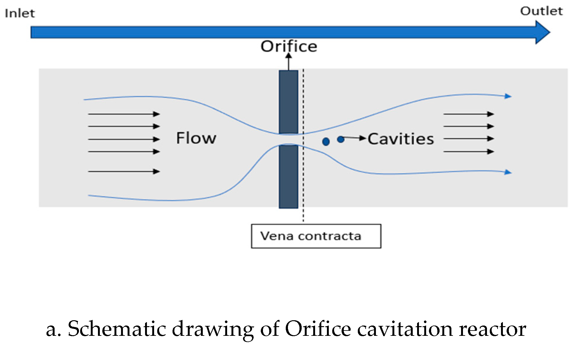
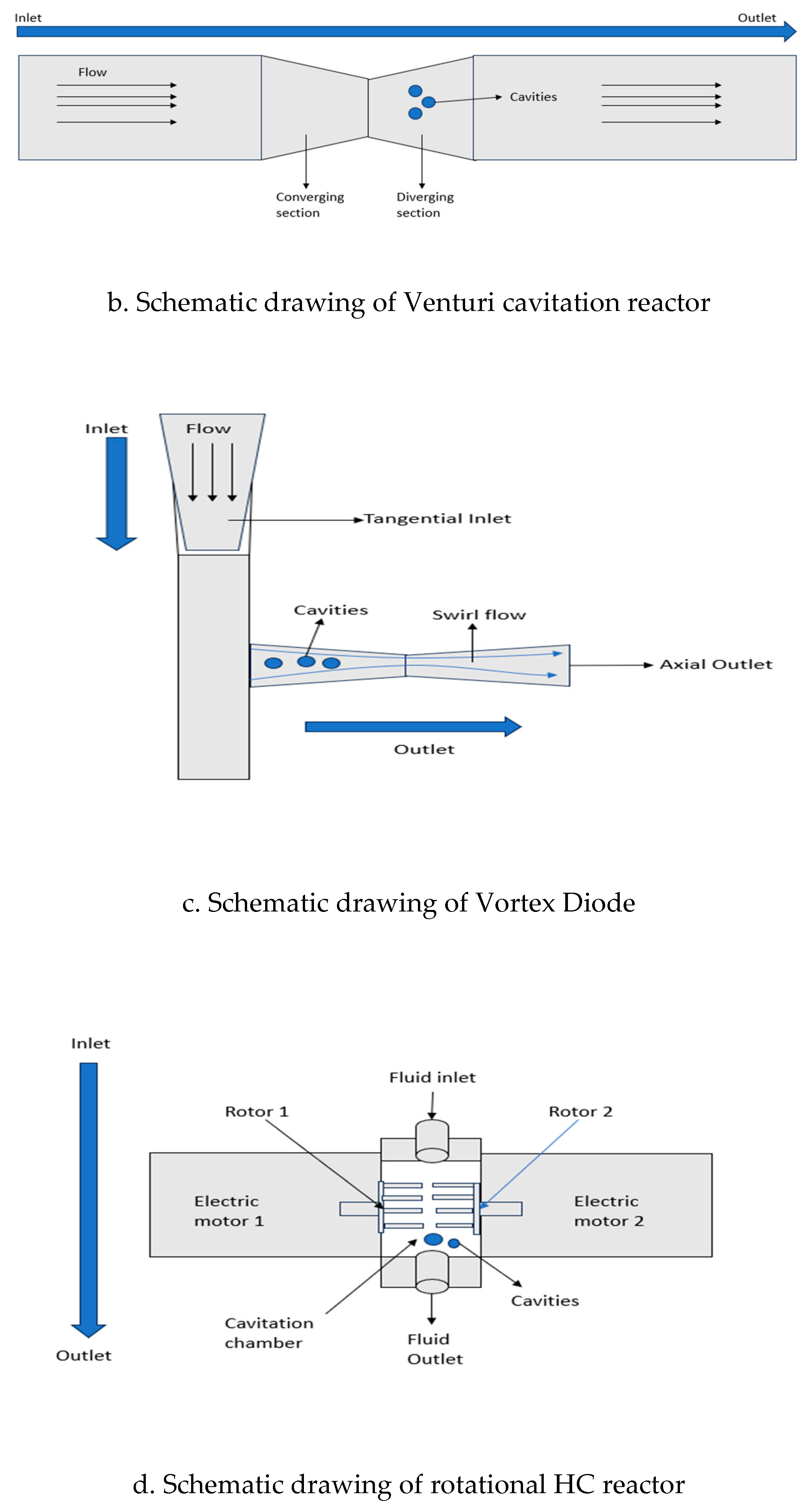
Figure 2.
Device types: orifices, venturi and vortex configurations.
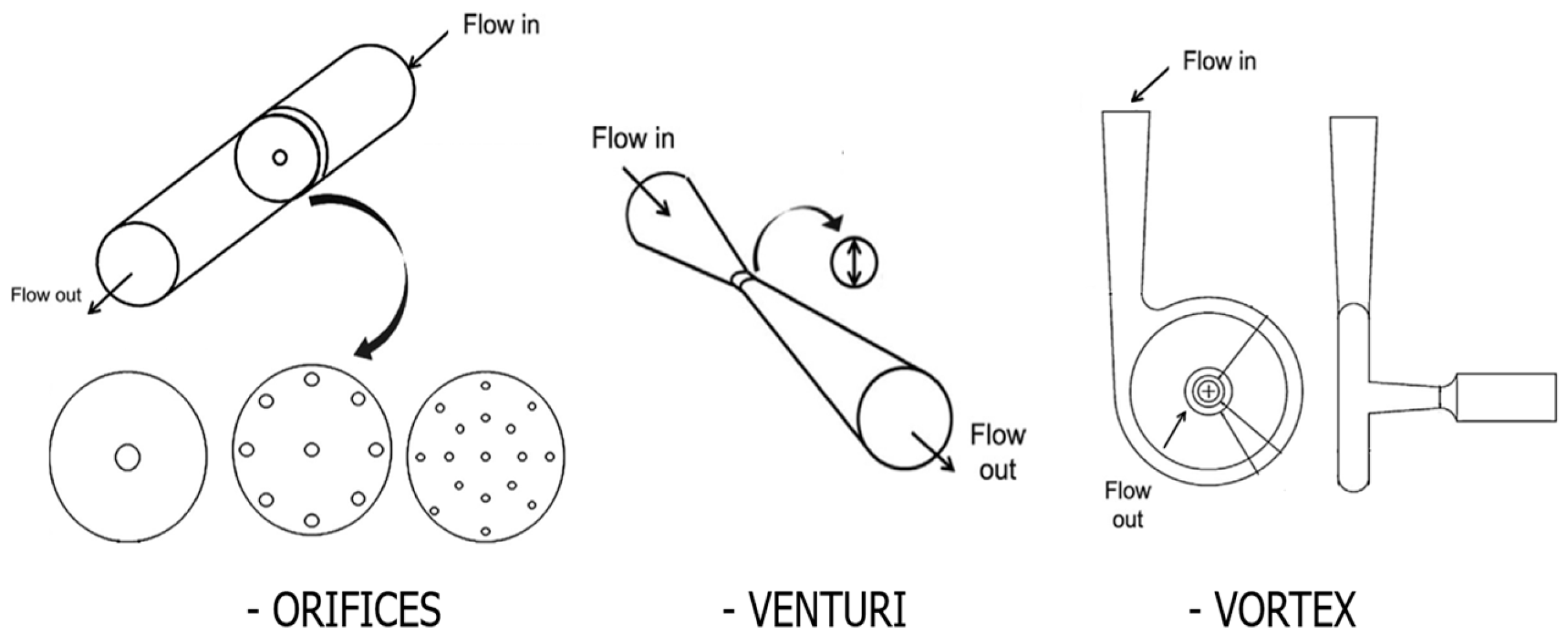
Figure 3.
Four ultrasonic units mounted in vertical.
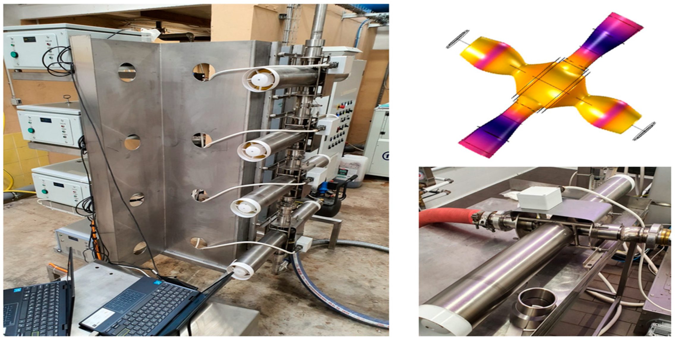
Figure 4.
Model of oscillations and a photo of an industrial tubular reactor system equipped with circular electroacoustic emitters. The unit operates at high pressure with SC-CO2.
Figure 4.
Model of oscillations and a photo of an industrial tubular reactor system equipped with circular electroacoustic emitters. The unit operates at high pressure with SC-CO2.
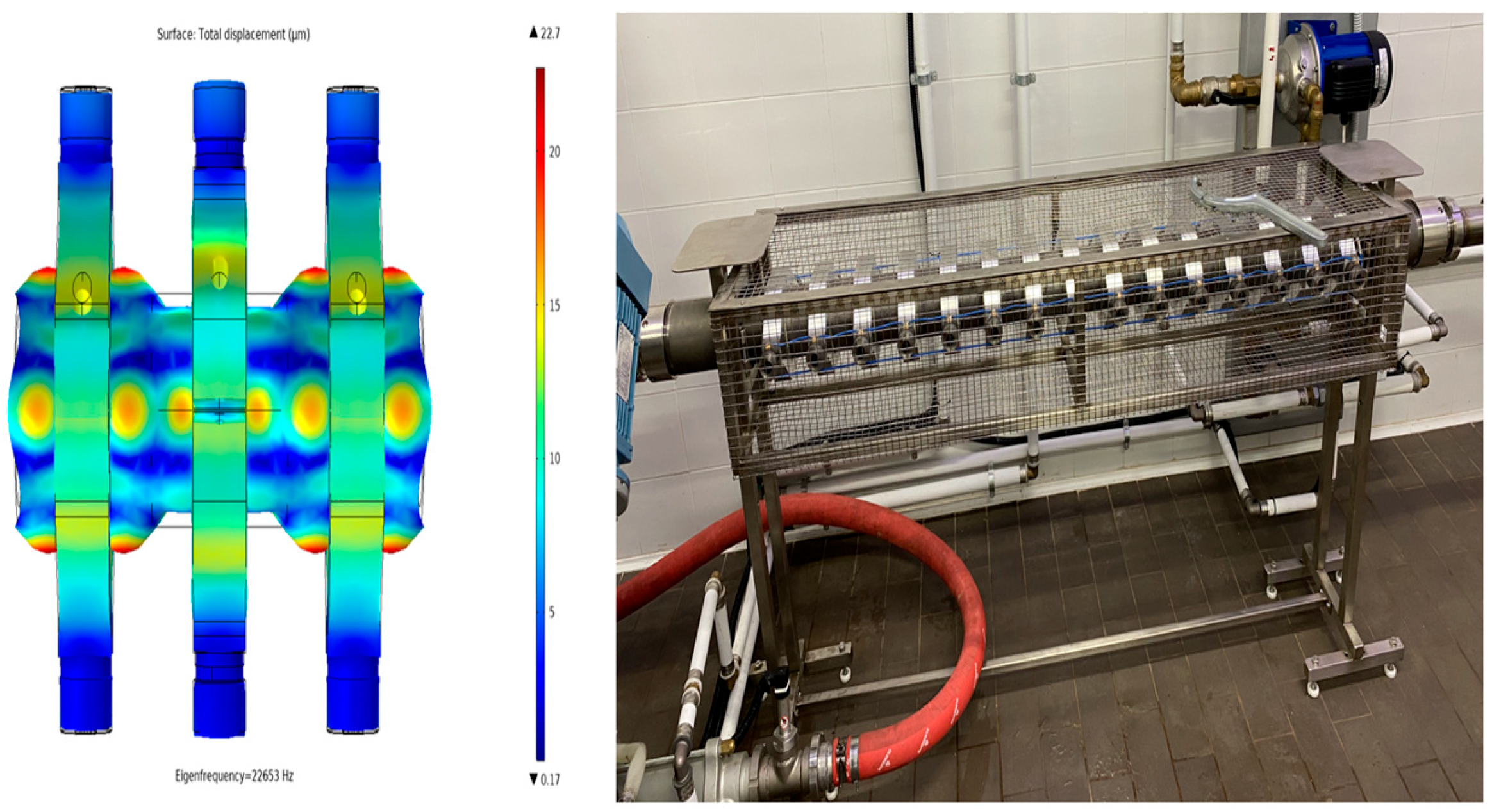
Figure 5.
Construction of a tubular flow-through reactor powered by two magnetostrictive transducers: 1 – Magnetostrictive transducers; 2 – Waveguides for translating longitudinal oscillations into radial oscillations; 3 – Tubular reactor; 4 – Electrical connections of the transducers; 5 – Cooling system inlets and outlets for the transducers; 6 – Rubber rings to prevent acoustic contact between the system and external elements.
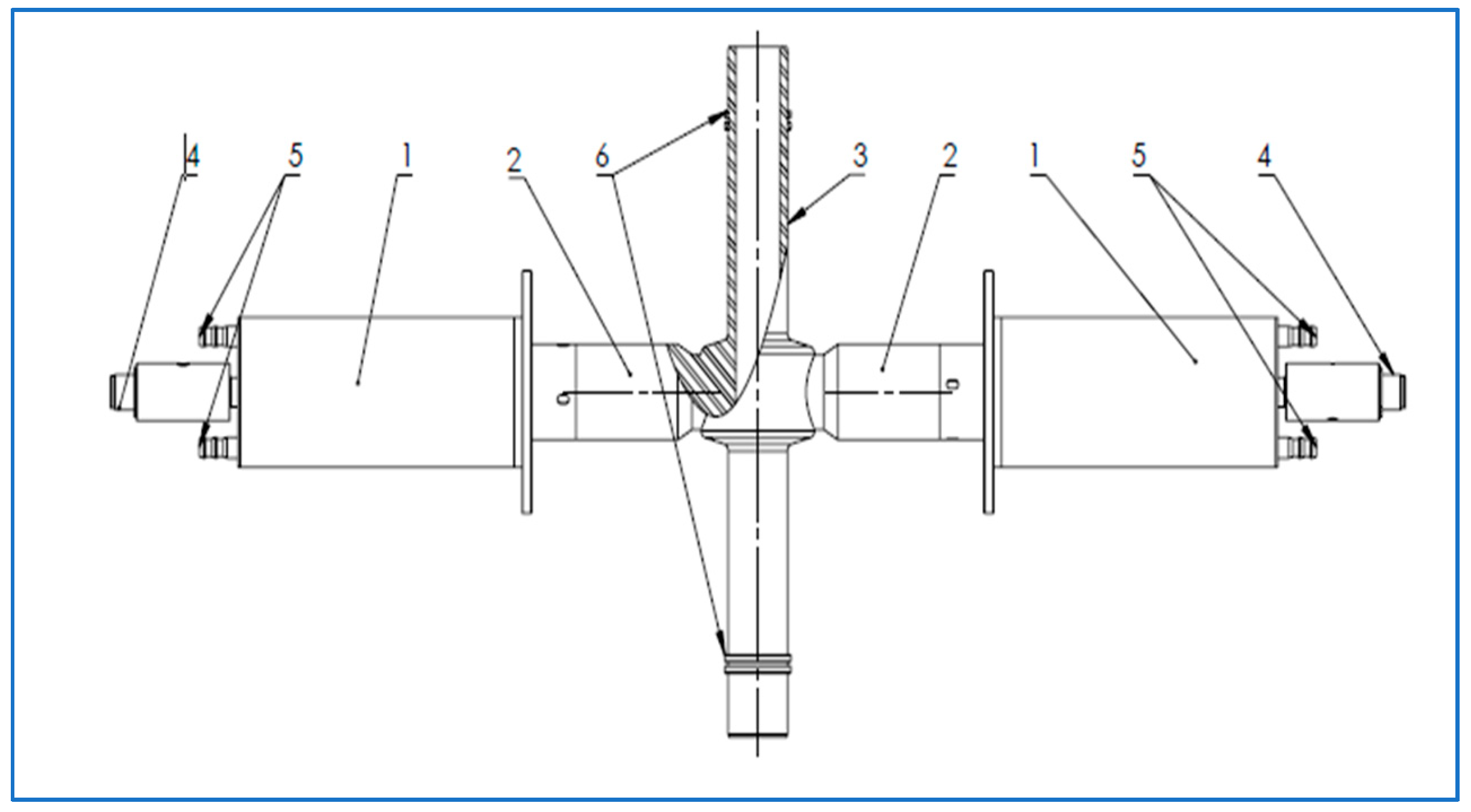
Figure 6.
Schematic representation of the hybrid HC-Plasma reactor and relevant components: 1. Reactor 2. Tank 3. Control panel 4. Chiller unit 5. Pump.
Figure 6.
Schematic representation of the hybrid HC-Plasma reactor and relevant components: 1. Reactor 2. Tank 3. Control panel 4. Chiller unit 5. Pump.
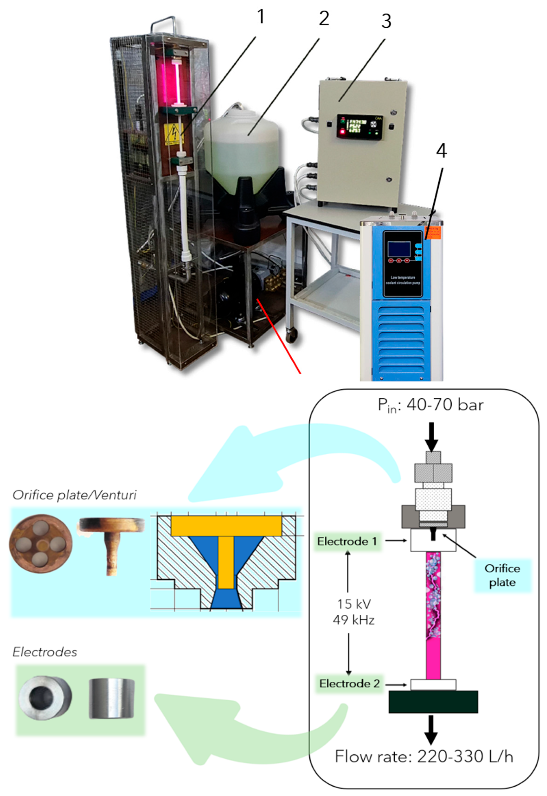
Figure 7.
Schematic representation of the semi-industrial HC-plasma prototype.
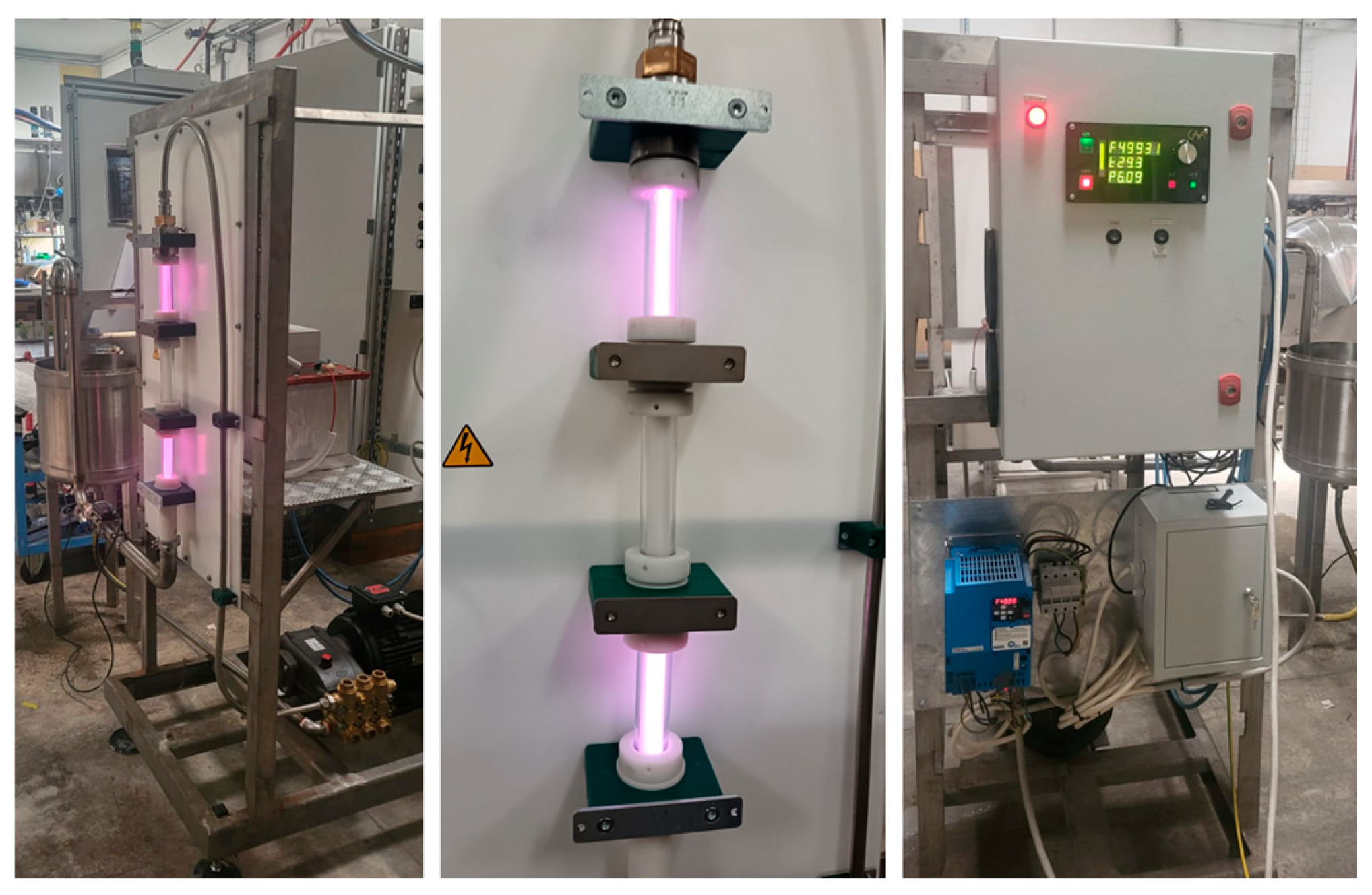
Figure 8.
Multi-emitters flow-through ultrasonic reactor for textiles coating with metal oxide nanoparticles.
Figure 8.
Multi-emitters flow-through ultrasonic reactor for textiles coating with metal oxide nanoparticles.
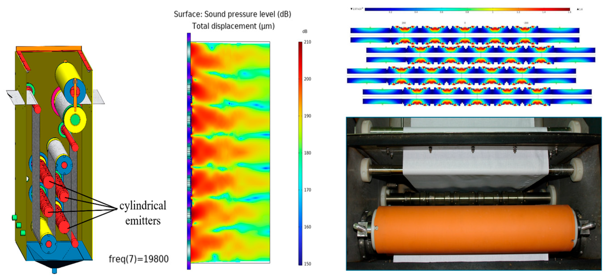
Table 1.
Reactor types and the effect of parameters on cavitation.
| Reactor Type | Parameters | Effect of parameters on cavitation |
|---|---|---|
| Orifice Plate | 1. L/D (Thickness to diameter of orifice) 2. β 3.α 4.ID of the pipe |
1.Minimum L/D values of 2 is preferred below which it affects pressure recovery and final collapse conditions. 2.Higher values of β, increases the collapse pressure of cavities. Lower values reduce the Cv improving the effect of cavitation and are counter balancing. 3. α values directly affect the shape and number of holes in the orifice reactors which in turn affect the cavity dynamics. 4.Increasing the ID of the pipe directly affects the velocity of the fluid, which affects the cavitation efficiency. |
| Venturi Tube | 1.γ 2.Convergence and divergence angle of venturi tube |
1. γ affects the residence time and growth of cavities in the system 2.The cavitation region within the tube and cavity dynamics depends on the converging and diverging section of venturi |
| Vortex Diode | 1.Diodicity 2.Throat diameter 3.Divergence angle of axial and tangential port 4.Nozzle dimension 5.Radius of curvature |
1.Diodicity depends on the Reynolds number of the fluid improving the efficiency of the device. 2.Increasing throat diameter affects the tangential velocity up to a scaling factor of 4 and levels off. 3.Increasing the divergence angle from 5 to 7ο enhances the diodicity of diode. 4.Nozzle with ID equal to height of the diode results in higher diodicity. 5.Increasing the radius of curvature increases forward pressure drop reducing the diodicity of device. |
| Rotational reactors | 1.Rotational Speed 2.Distance between the rotor and stator 3.Design of rotor blades |
1.The tangential fluid velocity depends on the rotational speed which determines the flow regime in the device 2.The effectiveness of cavitation directly depends on the distance between the plates 3.The design on the plate acts as a cavitation generating unit which governs the effectiveness of cavitation |
Disclaimer/Publisher’s Note: The statements, opinions and data contained in all publications are solely those of the individual author(s) and contributor(s) and not of MDPI and/or the editor(s). MDPI and/or the editor(s) disclaim responsibility for any injury to people or property resulting from any ideas, methods, instructions or products referred to in the content. |
© 2025 by the authors. Licensee MDPI, Basel, Switzerland. This article is an open access article distributed under the terms and conditions of the Creative Commons Attribution (CC BY) license (http://creativecommons.org/licenses/by/4.0/).
Copyright: This open access article is published under a Creative Commons CC BY 4.0 license, which permit the free download, distribution, and reuse, provided that the author and preprint are cited in any reuse.


