
Submitted:
17 October 2025
Posted:
20 October 2025
You are already at the latest version
Abstract
Wavelength-shifting (WLS) materials are used in radiation detectors to convert ultra-violet photons into visible light, enabling improved photon detection in systems such as scintillators and optical diagnostics for nuclear fusion devices. However, the long-term performance of these materials under radiation is still a critical issue in high-dose en-vironments. In this work, we investigated the radiation tolerance of three WLS com-pounds (TPB, NOL1, and SB2001), each deposited on reflective substrates (ESR and E-PTFE), resulting in six distinct WLS/substrate systems. The samples underwent gamma irradiation at absorbed doses of 100 kGy, 500 kGy, and 1000 kGy, as well as fast neutron (14.1 MeV) irradiation up to a fluence of 1.9×10¹³ n/cm². Photoluminescence and reflectance measurements were performed before and after irradiation to assess changes in optical performance. Gamma exposure caused spectral broadening in several samples, particularly those with TPB and SB2001, with Full Width at Half Maximum (FWHM) variations exceeding 10% at the highest doses. Neutron-induced effects were generally weaker and did not exhibit a clear fluence dependence. Reflectance degrada-tion was also observed, with variations depending on both the WLS material and the deposition method. These findings contribute to the understanding of WLS material stability under radiation and support their qualification for use in optical components exposed to harsh nuclear environments.
Keywords:
wavelength shifters
; gamma radiation
; neutron radiation
; ultraviolet light
; spectroscopic techniques
; radiation damage
; nuclear physics
1. Introduction
The detection of energetic particles is a fundamental aspect of nuclear physics, high-energy physics, and dark matter research [1,2,3,4,5,6,7,8]. A key component of modern particle detectors is the use of efficient Wavelength-Shifting (WLS) materials [9,10,11,12,13,14], which convert light from the ultraviolet (UV) region to wavelengths more compatible with the spectral sensitivity of photosensors. These materials are particularly valuable in applications such as helium-4 (⁴He) gas scintillation neutron detectors [15,16]. Detectors based on the scintillation properties of ⁴He are excellent candidates for measurements in fast neutron fields, due to the high elastic scattering cross-section of ⁴He with fast neutrons [17,18]. In this specific application, the ⁴He gas serves both as the interaction and scintillation medium. Since it emits light in the Extreme Ultraviolet (EUV) range (60–200 nm), WLS materials are employed to enhance light detection. These materials absorb the EUV photons and re-emit them in the visible range, enabling effective detection by photosensors. As with other structural and electronic components [19,20,21], such detectors are often employed in mixed radiation fields containing both gamma rays and neutrons, which demands the use of high-performance materials capable of withstanding harsh environments. Therefore, to accurately assess the performance of WLS-based optical systems (i.e., thin film substrate + WLS material), detailed characterization of their optical properties before and after irradiation is crucial.
In recent years, significant efforts have been devoted to characterizing and improving the performance of WLS materials, especially in harsh radiation environments [22]. Materials like Tetraphenyl Butadiene (TPB) [23] and Nanostructured Organosilicon Luminophores (NOLs) have emerged as promising candidates for these applications. TPB has been widely used in a variety of detectors [24], while NOLs, a newer class of materials [25,26], have shown potential for overcoming some of the limitations of conventional WLS systems. NOLs combine the properties of quantum dots and organic luminophores, offering high photoluminscence quantum yield, broad absorption spectra, and tunable emission characteristics [25], making them ideal candidates for use in high-radiation environments. These WLS materials are typically coupled with Silicon Photomultipliers (SiPMs) or Photomultiplier Tubes (PMTs), which are sensitive to the re-emitted light.
The optical properties of TPB films are known to vary significantly depending on film thickness, deposition technique, and substrate type. TPB exhibits particularly high fluorescence efficiency in the excitation wavelength range of 90–250 nm, exceeding that of standard reference materials such as sodium salicylate. The emission spectrum of TPB peaks at approximately 440 nm, which closely matches the region of maximum quantum efficiency of most PMTs (around 420 nm) [27]. However, organic WLS coatings such as TPB present several drawbacks, including instability in noble gas environments, photodegradation, and a limited Stokes shift, which results in self-absorption of the emitted light [14].
Beyond TPB, NOL materials have gained attention due to their excellent energy transfer efficiency and their applicability in various systems, including plastic scintillators, luminescent solar concentrators, and photodetectors. NOLs are particularly promising for applications requiring efficient down-conversion of high-energy photons. Their broad absorption spectrum, high absorptivity, and tunable optical properties can be tailored to match the peak detection sensitivity of common photodetectors. In this study, we focus on NOL-1, a specific NOL variant, and its application in shifting EUV light to wavelengths optimal for PMT performance.
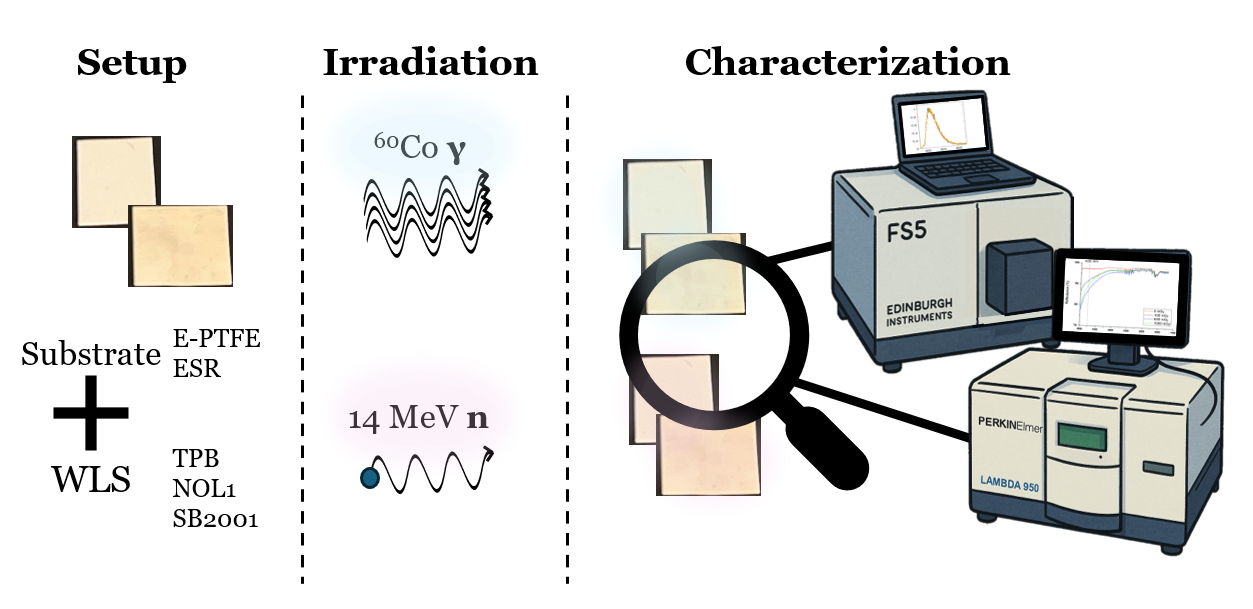
This paper investigates various WLS/substrate combinations, including TPB and NOL-1, before and after exposure to radiation. In addition, a new type of WLS material -a mixture of TPB and styrene in organic solvents, referred to as SB2001- was characterized. Six optical systems intended for use in particle detectors were studied, with reflectance measurements performed using a UV-Vis spectrophotometer and fluorescence measurements using a spectrofluorometer. The analysis primarily focused on variations in the optical response around 425 nm. Two identical batches of samples were prepared: the first was irradiated with gamma rays from a ⁶⁰Co source at total absorbed doses of 100 kGy, 500 kGy, and 1000 kGy, while the second was exposed to 14 MeV-neutrons at fluences of 0.96×10¹³, 1.45×10¹³, and 1.9×10¹³ n/cm². Following irradiation, the samples were re-characterized to evaluate how radiation exposure affected the performance of each WLS/substrate combination. The findings presented in this work contribute to a deeper understanding of the suitability and durability of different WLS materials and configurations for use in high-radiation environments, a critical factor for optimizing the design and operation of particle detectors in mixed radiation fields.
2. Materials and Methods
2.1. Samples
The study involved six groups of samples, realized by a private company, each defined by a specific combination of reflective substrate and WLS material. The coatings were fabricated using three different deposition techniques, as detailed in Table 1. Additionally, two uncoated substrate samples (ESR and E-PTFE) were analyzed to separately investigate their intrinsic properties and the effects of radiation exposure on the bare substrates.
The components consist of reflective substrates designed to enhance the photon collection efficiency of photomultiplier tubes while also providing mechanical support for the photoluminescent materials, which convert extreme ultraviolet radiation into visible light. A picture of the samples is reported in Figure 1. Two different bulk substrates were used: 3M Enhanced Specular Reflector® (ESR®) [28] and Expanded Polytetrafluoroethylene (E-PTFE) [29]. On each substrate, three different wavelength shifters were deposited using evaporation, liquid coating, or spray coating techniques: TPB, NOL1, and SB2001 (a proprietary blend of TPB and styrene in organic solvents). TPB is a widely used organic WLS, known for its strong fluorescence in the visible range when excited by UV light. It is typically deposited via thermal evaporation, forming a thin amorphous film. NOL1 and SB2001 are commercial organic fluorophores with similar spectral properties, although their detailed chemical composition is proprietary. In this study, these materials are used as functional coatings to convert UV photons into the visible range.
The WLS coatings have an estimated density of ~1.05 g/cm³ with a nominal thickness corresponding to a surface loading of 100 µg/cm² ± 50%.
2.2. Gamma and Neutron Irradiation
Gamma irradiation tests were carried out at the CALLIOPE facility of ENEA Casaccia Research Center in Rome. This pool-type irradiation facility is equipped with a high-activity 60Co gamma source enclosed in a shielded chamber (7 m × 6 m × 3.9 m) [30]. The source emits two gamma photons with an average energy of 1.25 MeV and a maximum activity of 3.7 × 10¹⁵ Bq. At the time of the experiment, the maximum available dose rate was approximately 5 kGy/h; for this study, a dose rate of 4.5 kGy/h was used.
The absorbed dose was measured using an alanine-EPR dosimetry system [31], and the values reported in this paper are referred to silicon. Samples were irradiated in air, at room temperature, and under dark conditions. They were divided into four groups, corresponding to total absorbed doses of 0 kGy, 100 kGy, 500 kGy, and 1000 kGy.
Neutron irradiation was performed at the Frascati Neutron Generator (FNG) of ENEA Frascati Research Center [32]. FNG is an accelerator-driven continuous neutron source based on deuterium–tritium (D-T) fusion reactions that produce quasi-monoenergetic 14.1 MeV neutrons isotropically, with a maximum emission rate of 10¹¹ n/s. Deuterons are accelerated up to 300 kV and 1 mA and directed onto a titanium target loaded with tritium. The D-T fusion reactions produce a neutron and an alpha particle (3.6 MeV) emitted in opposite directions [33].
2.3. Optical Characterization Techniques
Reflectance measurements were performed using a Perkin-Elmer Lambda 950 UV-Vis spectrophotometer [34], equipped with an integrating sphere for diffuse reflectance analysis. All tests were carried out in air, at room temperature, and under dark conditions. The spectral range analyzed was 400–700 nm. The integrating sphere, internally coated with Spectralon® [35], enabled the collection of all reflected light with high precision. Spectralon® exhibits >99% reflectance in the 400–1500 nm range and >95% in the 250–2500 nm range [36].
Measurements were performed in relative reflectance mode. Baseline corrections were conducted using a reference sample (Spectralon® or metallic glass). The relative measurement uncertainty was estimated to be 2%.
Photoluminescence (PL) measurements were conducted using an Edinburgh Instruments FS5 spectrofluorometer [37], equipped with two Czerny–Turner monochromators: one for selecting the excitation wavelength and the other for detecting the emitted signal. The emission spectra were recorded in the 350–650 nm range. Specifically, three acquisitions were taken from different areas of each sample, and the average spectrum is reported as the result. The parameters used for the PL measurements are summarized in Table 2. Excitation was provided by a xenon arc lamp, with the excitation wavelength set to 250 nm. The wavelength accuracy of both excitation and emission monochromators was ±0.5 nm.
3. Results and Discussion
In this section, we report and discuss the results obtained after gamma and neutron irradiation. Specifically, we first present the outcomes of the photoluminescence (PL) measurements, followed by those of the reflectance measurements, to evaluate the optical behavior of the analyzed samples in radiation-rich environments. Optical analyses were performed on both the front surface (with the WLS layer) and the rear surface of each sample. In some cases, particularly when the WLS layer was degraded, the substrate’s contribution became visible in the optical response, likely due to the thinness of the coating and the deposition technique employed. The final paragraph of this section addresses qualitative mechanical observations, focusing on embrittlement and detachment phenomena of the WLS layer after irradiation.
3.1. Photoluminescence Analysis
3.1.1. Gamma Irradiation Tests
We first analyzed the optical response of the bare substrates (E-PTFE and ESR), without any WLS coating. The average emission spectra for E-PTFE and ESR, normalized to their respective maxima, are shown in Figure 2 for each investigated absorbed dose. The graphs display three lines in different colors (yellow, orange and blue), each representing a distinct measurement of the same sample.
The E-PTFE substrate shows no significant emission in the spectral region of interest, and its emission remains unaffected by gamma irradiation. Conversely, ESR exhibits an emission peak around 420 nm, near the maximum quantum efficiency of typical photodetectors, and can therefore contribute to the total WLS signal. The unirradiated WLS/substrate samples display emission spectra qualitatively similar, in shape and peak position, to that of the ESR substrate (see ESR in Fig. 2), and the post-irradiation spectra closely align with their respective unirradiated references (data not shown). Since the spectral shapes remain largely unchanged, only the Full Width at Half Maximum (FWHM) was used as a representative parameter to quantify irradiation-induced variations and is therefore reported in the following. Figure 3 shows the evolution of FWHM as a function of absorbed gamma dose, while Table 3 lists the FWHM value for each sample before irradiation and the corresponding FWHM variations (ΔFWHM) at each dose level.
As reported in the literature [22], gamma irradiation tends to affect emission properties at total absorbed doses of approximately 500 kGy or higher. This trend is generally confirmed by our data, where most samples show significant spectral broadening (increased FWHM) at or above this dose level. Such broadening may be related to radiation-induced changes in the concentration of structural or molecular defects. According to previous studies, the linewidth of photoluminescence emission is influenced by the presence of impurities or defects, with narrower spectra typically observed in samples with lower defect densities [38]. Therefore, the increase in FWHM observed at higher doses may reflect the formation or activation of radiation-induced traps or localized emissive states, resulting in enhanced energetic disorder within the WLS layer.
3.1.2. Neutron Irradiation Tests
The PL response of the substrates (E-PTFE and ESR) following neutron exposure is reported in Figure 4.
Figure 4 clearly shows that neutron irradiation did not significantly affect the photoluminescence response of either substrate. The spectral profiles remain essentially unchanged, even at the maximum neutron fluence, suggesting that the optical emission properties of the substrates are insensitive to neutron exposure. As already mentioned in the discussion of PL behavior under gamma irradiation, the emission spectra of the WLS-coated samples resemble those of the ESR reference. Therefore, only the FWHM-based analysis is reported here to evaluate changes induced by neutron exposure. The evolution of FWHM is plotted in Figure 5, while Table 4 summarizes the FWHM value before irradiation along with the variations (ΔFWHM) at each neutron fluence level.
Except for the ESR+TPB and ESR+NOL1 samples at the highest fluence (1.9×10¹³ n/cm²), which show a marked broadening (ΔFWHM = +22.4 ± 2.7 nm and ΔFWHM = +9.7 ± 4.3 nm, respectively), all samples exhibited good stability under neutron exposure, with ΔFWHM remaining within the uncertainties. No clear fluence-dependent degradation trend is observed, suggesting that neutron-induced damage within the studied fluence range is generally limited or negligible for most WLS/substrate combinations. The spectral broadening observed in a few cases may suggest the formation of additional defect states, although to a significantly lesser extent than that induced by gamma irradiation.
3.2. Reflectance Spectra
3.2.1. Gamma Irradiation Tests
To evaluate gamma irradiation effects, reflectance at 425 nm (the region of peak efficiency for most photodetectors [39]) was studied. The difference ΔR (%) at this wavelength, representing the change in reflectance with dose, was used as a degradation indicator. Figure 6 shows the reflectance spectra of the bare substrates (E-PTFE and ESR) before and after irradiation at absorbed doses of 100 kGy, 500 kGy, and 1000 kGy, as an example. The two materials display distinct optical behaviors. The E-PTFE substrate exhibits negligible changes in reflectance after irradiation, while the ESR substrate shows a variation of approximately 8% at 425 nm after 1000 kGy of absorbed dose. This difference can be attributed to gamma-induced surface hardening or roughening, which reduces specular reflectance and increases diffuse scattering [40,41].
Table 5 reports the R (%) values at 425 nm before irradiation for all samples, along with the corresponding ΔR (%) values at 425 nm after the different irradiation steps (100 kGy, 500 kGy, and 1000 kGy), relative to the unirradiated spectrum. Overall, all WLS-coated samples exhibited a ΔR greater than 10% at the highest dose level (1000 kGy), except for the ESR+NOL1 sample, which showed the smallest variation. These results indicate that gamma irradiation can significantly affect optical properties such as reflectance, through various mechanisms that alter the polymer structure of the substrate or induce the formation of defects that modify the material’s band structure. Such mechanisms may include main chain degradation, chain scission, free radical formation, and cross-linking within the polymer matrix [8,42,43]. Moreover, when WLS layers are deposited on reflective substrates, gamma exposure may also alter these substrates by oxidation or by inducing changes in their microstructure, further affecting the overall reflectance and mechanical stability [44,45].
From Figure 6 it is evident that E-PTFE shows minimal change (<1%), whereas ESR exhibits about 10% change after 1000 kGy, likely due to surface roughening that reduces specular reflectance.

Table 5.
Reflectance values R (%) at 425 nm before irradiation and corresponding ΔR (%) variations relative to 0 kGy, for increasing absorbed doses. Measurement uncertainty: ± 2%.
Table 5.
Reflectance values R (%) at 425 nm before irradiation and corresponding ΔR (%) variations relative to 0 kGy, for increasing absorbed doses. Measurement uncertainty: ± 2%.
| Sample | R (%) @425 nm 0 kGy |
ΔR (%) @425 nm 100 kGy | ΔR (%) @425 nm 500 kGy | ΔR (%) @425 nm 1000 kGy | |
|---|---|---|---|---|---|
| Substrate | |||||
| E-PTFE | 98.92 | 0.32 | -0.27 | -0.34 | |
| ESR | 97.22 | -5.7 | -10.30 | -7.94 | |
| WLS/substrate system | |||||
| E-PTFE+TPB (evaporation) |
98.14 | -4.81 | -10.56 | -6.44 | |
| ESR+TPB (evaporation) |
95.66 | -7.60 | -17.21 | -28.98 | |
| E-PTFE+NOL1 (liquid coating) |
98.05 | -9.98 | -20.54 | -29.45 | |
| ESR+NOL1 (liquid coating) |
96.69 | 0.12 | -1.039 | -5.56 | |
| E-PTFE+SB2001 (spray coating) |
98.15 | -5.97 | -9.17 | -13.58 | |
| ESR+SB2001 (spray coating) |
96.78 | -4.54 | -15.57 | -18.86 | |
It is worth noting that some of the observed optical degradation, especially in samples produced via evaporation, may partly originate from pre-existing defects such as non-uniform deposition or weak WLS substrate adhesion, rather than from gamma irradiation alone. In fact, during sample handling we observed partial detachment of the WLS layer, as traces were found on the gloves after manipulation.
3.2.2. Neutron Irradiation Tests
The optical reflectance of all samples was measured before and after neutron irradiation. Figure 7 reports the reflectance spectra for the two bare substrates (E-PTFE and ESR), as an example. In this case, both substrates exhibit stable optical behavior under neutron exposure: the E-PTFE shows a ΔR (%) at λ = 425 nm of less than 1%, while the ESR substrate shows a slightly higher variation, around 1.6%.
Table 6 summarizes the reflectance values (R %) at 425 nm before irradiation for all samples, along with the corresponding ΔR (%) values after neutron irradiation at different fluence levels.
Overall, neutron irradiation at the tested fluence levels did not significantly affect the optical reflectance or wavelength-shifting performance of the samples, with ΔR (%) remaining below 10% in all cases except for the E-PTFE+SB2001 sample. This limited impact is likely due to the relatively low neutron fluence employed in the current study. Higher fluences may be investigated in future work to assess potential long-term effects. The pronounced variation observed in the E-PTFE+SB2001 sample may be attributed more to the specific deposition method and WLS formulation than to neutron-induced damage. In general, neutron radiation in polymers can promote cross-linking or chain scission [46,47], potentially altering surface morphology and reducing reflectance [48,49].
In addition to the optical analyses, some qualitative observations were made on the physical appearance and integrity of the WLS coatings after irradiation. In particular, for samples prepared via evaporation, minor detachment or residue of the WLS layer were occasionally noticed during post-irradiation handling. For example, traces of material were found on gloves after manipulating certain samples, suggesting a possible weakening of the interface between the WLS layer and the substrate. While no systematic mechanical testing was conducted, these observations may point to irradiation-induced effects, such as changes in adhesion or microstructural alterations of the coating, which could contribute to the optical degradation trends described above. Further studies would be required to quantitatively evaluate the mechanical stability of the coatings under irradiation.
5. Conclusions
In this work, gamma and neutron irradiation tests were performed on wavelength-shifting coatings deposited on reflective substrates (E-PTFE and ESR), and their optical properties were characterized through photoluminescence and reflectance measurements. The E-PTFE substrate itself showed negligible photoluminescence in the spectral region of interest, making it unsuitable for direct PL analysis, whereas the ESR substrate exhibited a stable and appreciable PL signal. Regarding gamma irradiation effects, a general trend of degradation was observed in both photoluminescence and reflectance properties, with gamma doses above 500 kGy causing more pronounced spectral broadening and reflectance changes. A comparative analysis of the samples highlights that coatings deposited on ESR substrates generally performed better in terms of mechanical stability, WLS adhesion, and resistance to optical degradation under gamma irradiation. In particular, ESR+NOL1 and ESR+SB2001 samples stood out for their excellent post-irradiation photoluminescence and reflectance retention, while E-PTFE-based samples, especially those coated with TPB and NOL1, showed poor adhesion, increased brittleness, and greater sensitivity to gamma-induced damage. Results after neutron irradiation showed that, at the tested fluence (0.96×10¹³, 1.45×10¹³, and 1.9×10¹³ n/cm²) levels, this type of radiation caused only minor effects on the optical properties compared to gamma irradiation. This behaviour is consistent with the relatively low neutron fluences employed, which are well below those expected in fusion reactor environments. Overall, these results indicate that the choice of substrate and WLS deposition method strongly influences both the optical and mechanical stability of the coatings under gamma irradiation, and that ESR-based samples with carefully controlled WLS layers emerged as particularly promising for radiation-rich applications. Future work will focus on extending neutron irradiation tests to higher fluence levels, more representative of fusion or high-intensity neutron environments. In addition, surface characterization using Scanning Electron Microscopy is planned to investigate gamma-induced morphological changes, such as roughening, which could explain the observed degradation in reflectance and photoluminescence properties.
Author Contributions
B.D.O, F.F., J.S: Writing—review & editing, Writing—original draft, Visualization, Validation, Methodology, Investigation, Formal analysis, Data curation, Conceptualization. A.C.: Supervision, Visualization, Data curation & review. S.C, B.E. and A.V.: review & editing. A.C., I.D.S., D.F., S.L., D.M. and G.P.: Visualization. All authors have read and agreed to the published version of the manuscript.
Data Availability Statement
The data that support the findings of this study are available from the corresponding authors upon reasonable request.
Conflicts of Interest
The authors declared that they have no conflicts of interest in this work. We declare that we do not have any commercial or associative interest that represents a conflict of interest related to this work.
References
- B. Esposito, D. Marocco, G. Gandolfo, F. Belli, L. Bertalot, J. Blocki, D. Bocian, G. Brolatti, M. Cecconello, C. Centioli, R.C. Pereira, S. Conroy, F. Crescenzi, N. Cruz, L. de Bilbao, A. Domenicone, Q. Ducasse, G. Di Mambro, D. Dongiovanni, I. Eletxigerra, B. Etxeita, A. Fernandez, O. Ficker, P. Gallina, T. Giacomin, G. Ginoulhiac, J. Godlewski, A. Hjalmarsson, M. Imrisek, R. Kantor, K. Kasprzak, J. Kotula, V. Krasilnikov, M. Lewandowska, A. Maffucci, U. Marotta, D. Marzullo, G. Mazzitelli, G. Mazzone, R. Miklaszewski, K. Mikszuta-Michalik, W. Maciocha, S. Magagnino, M. Misano, J. Mlynar, C. Monti, F. Moro, R. Ortwein, M. Passeri, T. Pinna, E. Pirovano, V. Pisciotta, F. Pompili, S. Podda, M. Riva, B. Santos, J. Sousa, J. Swierblewski, P. Szklarz, A. Tatí, S. Ventre, F. Villone, N. Virgili, A. Zimbal, Progress of Design and Development for the ITER Radial Neutron Camera, Journal of Fusion Energy 41 (2022) 1–16. [CrossRef]
- S. Cesaroni, D. Marocco, D. Marzullo, F. Moro, F. Belli, G. Brolatti, C. Centioli, E. Occhiuto, M. Riva, G. Rocchi, B. Esposito, Design of a position monitoring system for the ITER radial neutron camera, Fusion Engineering and Design 203 (2024). [CrossRef]
- F. Moro, B. Esposito, D. Marocco, S. Podda, F. Pompili, M. Riva, D. Flammini, A. Colangeli, R. Kantor, The ITER radial neutron camera in-port system: Nuclear analyses in support of its design development, Fusion Engineering and Design 146 (2019) 236–241. [CrossRef]
- D. Marzullo, E. Occhiuto, G. Brolatti, D. Falco, D. Laghi, D. Marocco, B. Esposito, Mechanical design of ITER radial neutron camera Ex-Port system, Fusion Engineering and Design 203 (2024). [CrossRef]
- A. Cemmi, A. Colangeli, B. D’orsi, I. Di Sarcina, E. Diociaiuti, S. Fiore, D. Paesani, M. Pillon, A. Saputi, I. Sarra, D. Tagnani, Radiation study of Lead Fluoride crystals, Journal of Instrumentation 17 (2022) T05015. [CrossRef]
- Cemmi, V.L. Ciccarella, B. D’orsi, E. Di Meco, I. Di Sarcina, E. Diociaiuti, R. Gargiulo, M. Moulson, I. Sarra, J. Scifo, A. Verna, Radiation resistance of the Muon Collider CRILIN calorimeter prototype equipped with Cherenkov lead fluoride crystals, IEEE Trans Nucl Sci (2025). [CrossRef]
- F.M. Addesa, P. Barria, R. Bianco, M. Campana, F. Cavallari, A. Cemmi, M. Cipriani, I. Dafinei, B. ď Orsi, D. del Re, M. Diemoz, G. ď Imperio, E. Di Marco, I. Di Sarcina, M. Enculescu, E. Longo, M.T. Lucchini, F. Marchegiani, P. Meridiani, S. Nisi, G. Organtini, F. Pandolfi, R. Paramatti, V. Pettinacci, C. Quaranta, S. Rahatlou, C. Rovelli, F. Santanastasio, L. Soffi, R. Tramontano, C.G. Tully, Comparative characterization study of LYSO:Ce crystals for timing applications, Journal of Instrumentation 17 (2022). [CrossRef]
- A. Cemmi, B. D’Orsi, E. Di Meco, I. Di Sarcina, E. Diociaiuti, M. Moulson, D. Paesani, I. Sarra, J. Scifo, A. Verna, The CRILIN calorimeter: gamma radiation resistance of crystals and SiPMs, Journal of Instrumentation 19 (2024) P10016. [CrossRef]
- M. Kuźniak, A.M. Szelc, Wavelength Shifters for Applications in Liquid Argon Detectors, Instruments 2021, Vol. 5, Page 4 5 (2020) 4. [CrossRef]
- D.Y. Akimov, A. V. Akindinov, I.S. Alexandrov, V.A. Belov, O. V. Borshchev, A.A. Burenkov, M. V. Danilov, A.G. Kovalenko, Y.N. Luponosov, S.A. Ponomarenko, V.N. Stekhanov, N.M. Surin, S.A. Zavyalov, M.Y. Yablokov, Development of VUV wavelength shifter for the use with a visible light photodetector in noble gas filled detectors, Nucl Instrum Methods Phys Res A 695 (2012) 403–406. [CrossRef]
- T. Yagi, T. Misawa, C.H. Pyeon, S. Shiroya, A small high sensitivity neutron detector using a wavelength shifting fiber, Applied Radiation and Isotopes 69 (2011) 176–179. [CrossRef]
- A.I. Bolozdynya, A.W. Bradley, P.P. Brusov, C.E. Dahl, J. Kwong, T. Shutt, Using a wavelength shifter to enhance the sensitivity of liquid xenon dark matter detectors, IEEE Trans Nucl Sci 55 (2008) 1453–1457. [CrossRef]
- S. Magill, M. Nayfeh, M. Fizari, J. Malloy, Y. Maximenko, J. Xie, H. Yu, Enhanced UV light detection using wavelength-shifting properties of Silicon nanoparticles, Journal of Instrumentation 10 (2015) P05008. [CrossRef]
- S. Sahi, S. Magill, L. Ma, J. Xie, W. Chen, B. Jones, D. Nygren, Wavelength-shifting properties of luminescence nanoparticles for high energy particle detection and specific physics process observation, Sci Rep 8 (2018) 1–9. [CrossRef]
- J.M. Lewis, R.P. Kelley, D. Murer, K.A. Jordan, Fission signal detection using helium-4 gas fast neutron scintillation detectors, Appl Phys Lett 105 (2014) 7. [CrossRef]
- V.M. Gehman, S.R. Seibert, K. Rielage, A. Hime, Y. Sun, D.M. Mei, J. Maassen, D. Moore, Fluorescence efficiency and visible re-emission spectrum of tetraphenyl butadiene films at extreme ultraviolet wavelengths, Nucl Instrum Methods Phys Res A 654 (2011) 116–121. [CrossRef]
- S. Cesaroni, D. Marocco, V. Anagnostopoulou, F. Belli, A. Colangeli, N. Fonnesu, S. Loreti, F. Moro, G. Pagano, E. Pirovano, F. Pompili, M. Pontesilli, A. Zimbal, B. Esposito, Characterization of a new 4He scintillator detector prototype for the ITER Radial Neutron Camera, Fusion Engineering and Design 215 (2025) 114948. [CrossRef]
- Q. Ducasse, B. Esposito, A. Zimbal, M. Riva, D. Marocco, S. Podda, Characterization of the response and the intrinsic efficiency of a 4He scintillation detector to fast mono-energetic neutrons, Nucl Instrum Methods Phys Res A 998 (2021) 165168. [CrossRef]
- D’Orsi, C. Altomare, A. Ampollini, M.D. Astorino, G. Bazzano, E. Catrix, A. Cemmi, A. Colangeli, I. Di Sarcina, D.S. Lazzaro, R. Lelièvre, S. Loreti, S. Fourmaux, J. Fuchs, P. Nenzi, G. Pagano, F. Panza, C. Ronsivalle, J. Scifo, S. Vallières, P. Antici, Laser-driven proton sources for efficient radiation testing, Scientific Reports 2025 15:1 15 (2025) 1–11. [CrossRef]
- P. Martínez-Albertos, P. Sauvan, M.J. Loughlin, Y. Le Tonqueze, R. Juárez, Assessment of ITER radiation environment during the remote-handling operation of In-Vessel components with D1SUNED, Sci Rep 13 (2023) 1–12. [CrossRef]
- F. Faccio, ASIC survival in the radiation environment of the LHC experiments: 30 years of struggle and still tantalizing, Nucl Instrum Methods Phys Res A 1045 (2023) 167569. [CrossRef]
- Y. Fan, C. Wen, J. Wu, Z. Li, Y. Liu, H. Gao, M. Li, L. Zeng, H. Zhou, S. Dai, Q. Xie, X. Fan, Effects of alpha particle and gamma irradiation on the 1,1,4,4-tetraphenyl-1,3-butadiene wavelength shifter, Radiation Physics and Chemistry 176 (2020) 109058. [CrossRef]
- J.R. Graybill, C.B. Shahi, M.A. Coplan, A.K. Thompson, R.E. Vest, C.W. Clark, Extreme ultraviolet photon conversion efficiency of tetraphenyl butadiene, Appl Opt 59 (2020) 1217. [CrossRef]
- W.M. Burton, B.A. Powell, Fluorescence of Tetraphenyl-Butadiene in the Vacuum Ultraviolet, Appl Opt 12 (1973) 87. [CrossRef]
- S.A. Ponomarenko, N.M. Surin, O. V. Borshchev, M.S. Skorotetcky, A.M. Muzafarov, Nanostructured organosilicon luminophores as a new concept of nanomaterials for highly efficient down-conversion of light, Nanophotonic Materials XII 9545 (2015) 954509. [CrossRef]
- D.Y. Akimov, V.A. Belov, O. V. Borshchev, A.A. Burenkov, Y.L. Grishkin, A.K. Karelin, A. V. Kuchenkov, A.N. Martemiyanov, S.A. Ponomarenko, G.E. Simakov, V.N. Stekhanov, N.M. Surin, V.S. Timoshin, O.Y. Zeldovich, Test of SensL SiPM coated with NOL-1 wavelength shifter in liquid xenon, Journal of Instrumentation 12 (2017) P05014. [CrossRef]
- R. Francini, R.M. Montereali, E. Nichelatti, M.A. Vincenti, N. Canci, E. Segreto, F. Cavanna, F. Di Pompeo, F. Carbonara, G. Fiorillo, F. Perfetto, VUV-Vis optical characterization of Tetraphenyl-butadiene films on glass and specular reflector substrates from room to liquid Argon temperature, Journal of Instrumentation 8 (2013) P09006. [CrossRef]
- 3M, 3MTM Enhanced Specular Reflector Films, (n.d.). https://multimedia.3m.com/mws/media/1245089O/3m-enhanced-specular-reflector-films-3m-esr-tech-data-sheet.pdf (accessed July 24, 2025).
- GORE®, GORE® GR Sheet Gasketing, (n.d.). https://www.gore.com/sites/default/files/2025-04/gore-gr-sheet-gasketing-datasheet-en-2025.pdf (accessed July 24, 2025).
- S. Baccaro, A. Cemmi, I. Di Sarcina, G. Ferrara, Gamma irradiation Calliope facility at ENEA-Casaccia Research Centre (Rome, Italy), RT/2019/4/ENEA (2019).
- ISO/ASTM 51607:2013 - Practice for use of the alanine-EPR dosimetry system, (2013). https://www.iso.org/standard/62955.html.
- M. Capogni, A. Pietropaolo, L. Quintieri, A. Fazio, P. De Felice, M. Pillon, A. Pizzuto, 99mTc by 99Mo produced at the ENEA-FNG facility of 14 MeV neutrons, Applied Radiation and Isotopes 134 (2018) 105–107. [CrossRef]
- A. et al Pietropaolo, The Frascati Neutron Generator: A multipurpose facility for physics and engineering, Journal of Physics: Confere4nce Series 1021 (2018).
- PerkinElmer, LAMBDA UV/Vis and UV/Vis/NIR Spectrophotometers , (n.d.). https://perkinelmer.com.ar/wp-content/uploads/sites/3/2018/05/BRO_LAMBDA_850_950_1050_008021B_01.pdf (accessed July 25, 2025).
- Labsphere, Spectralon® Diffuse Reflectance Material, (n.d.). https://www.labsphere.com/wp-content/uploads/2023/01/Spectralon.pdf (accessed July 24, 2025).
- G.T. Georgiev, J.J. Butler, Long-term calibration monitoring of Spectralon diffusers BRDF in the air-ultraviolet, Appl Opt 46 (2007) 7892–7899. [CrossRef]
- Edimburgh Instruments, Spectrofluorometer FS5, n.d. https://www.edinst.com/wp-content/uploads/2019/03/EI_FS5-Brochure_16pp_FINAL_WEB-compressed.pdf.
- S.S. Kostina, J.A. Peters, W. Lin, P. Chen, Z. Liu, P.L. Wang, M.G. Kanatzidis, B.W. Wessels, Photoluminescence fatigue and inhomogeneous line broadening in semi-insulating Tl6SeI4 single crystals, Semicond Sci Technol 31 (2016). [CrossRef]
- Hamamatsu, Photomultiplier Tubes Basics and Applications , (n.d.). https://www.hamamatsu.com/content/dam/hamamatsu-photonics/sites/documents/99_SALES_LIBRARY/etd/PMT_handbook_v4E.pdf (accessed July 24, 2025).
- W.J. Zhang, J. Qiu, L.H. Liu, Deviation characteristics of specular reflectivity of micro-rough surface from Fresnel’s equation, J Quant Spectrosc Radiat Transf 160 (2015) 50–62. [CrossRef]
- D.K.P. Huckaby, D.R. Cairns, Quantifying “Sparkle” of Anti-Glare Surfaces, SID Symposium Digest of Technical Papers 40 (2009) 511. [CrossRef]
- A. Cemmi, I. Di Sarcina, B. D’Orsi, Gamma radiation-induced effects on paper irradiated at absorbed doses common for cultural heritage preservation, Radiation Physics and Chemistry 202 (2023) 110452. [CrossRef]
- A.T. Naikwadi, B.K. Sharma, K.D. Bhatt, P.A. Mahanwar, Gamma Radiation Processed Polymeric Materials for High Performance Applications: A Review, Front Chem 10 (2022) 837111. [CrossRef]
- W.H. Gourdin, P. Datte, W. Jensen, H. Khater, M. Pearson, S. Girard, P. Paillet, E. Alozy, Effect of gamma and neutron irradiation on the mechanical properties of SpectralonTM porous PTFE, Fusion Engineering and Design 112 (2016) 343–348. [CrossRef]
- Z. Rafiei Sarmazdeh, Gamma Radiation Effects on the Mechanical Stability of Polyethylene Composites: Effects of Filler Dimension and Absorbed Dose, Journal of Nuclear Research and Applications 4 (2024) 11–22. [CrossRef]
- Barta, M. Fernández-Álvarez, E.M. Ruiz-Navas, Analysis of the Effects of Neutron Radiation on Cellulose Linen Fabrics Using Non-Destructive Testing, Polymers 2024, Vol. 16, Page 3401 16 (2024) 3401. [CrossRef]
- K. Ishigure, S. Egusa, S. Tagawa, Y. Tabata, Effect of neutron irradiation on polymers, Radiation Physics and Chemistry (1977) 14 (1979) 585–594. [CrossRef]
- H. Na, J. Yoo, H. Ki, Prediction of surface morphology and reflection spectrum of laser-induced periodic surface structures using deep learning, J Manuf Process 84 (2022) 1274–1283. [CrossRef]
- F. Marchini, C. Fabiani, L. Latterini, A.L. Pisello, Optimising surface morphology for enhanced radiative properties in thermal energy-efficient materials, Mater Today Energy 45 (2024) 101660. [CrossRef]
Figure 1.
Photograph of one representative sample from each group, with labels.
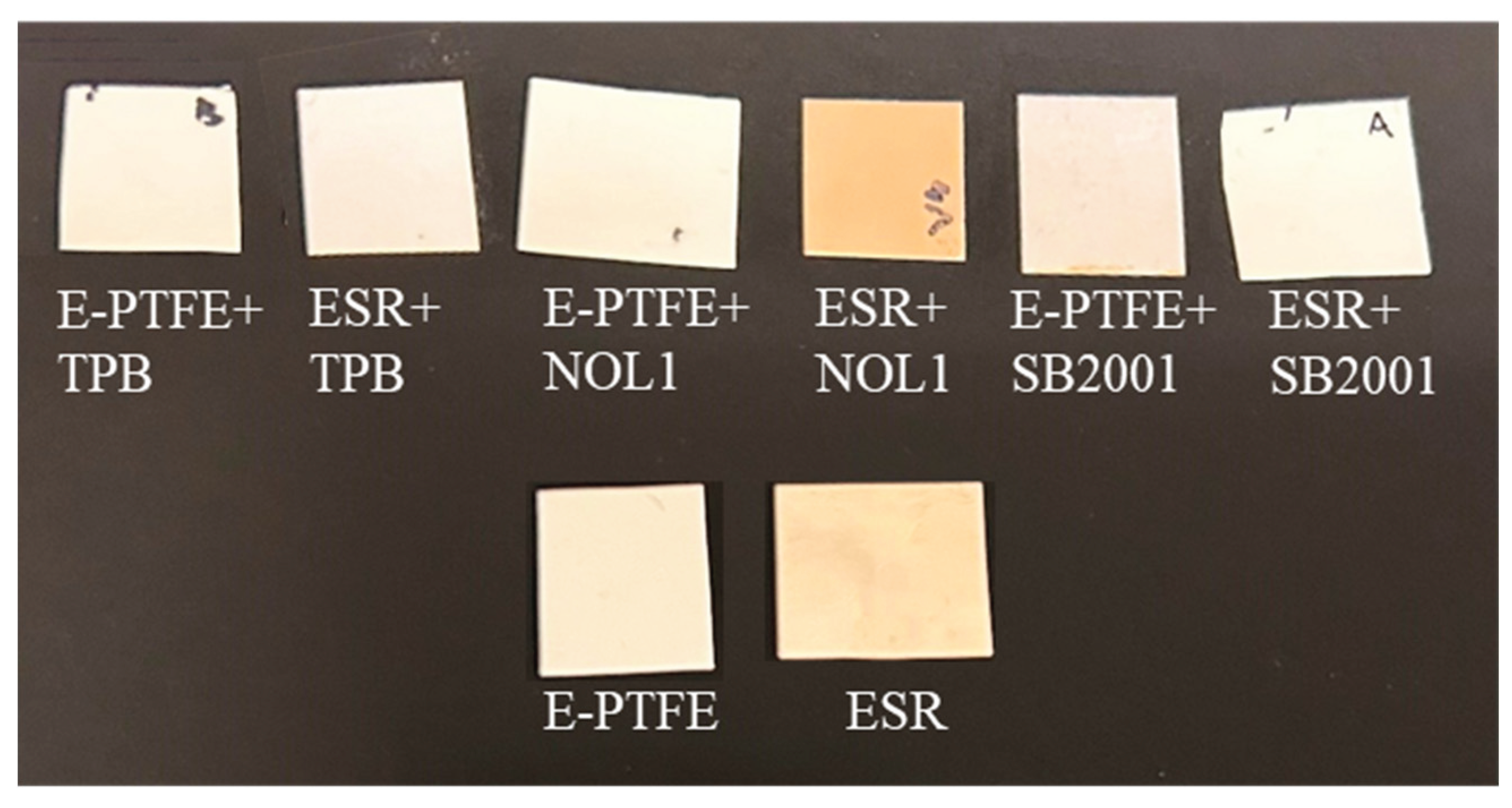
Figure 2.
Normalized emission spectra of E-PTFE (top) and ESR (bottom) substrates, obtained using an excitation wavelength of 250 ± 0.5 nm, before and after gamma irradiation. The three distinct colors (yellow, orange and blue) represent three independent measurements performed on the same sample.
Figure 2.
Normalized emission spectra of E-PTFE (top) and ESR (bottom) substrates, obtained using an excitation wavelength of 250 ± 0.5 nm, before and after gamma irradiation. The three distinct colors (yellow, orange and blue) represent three independent measurements performed on the same sample.
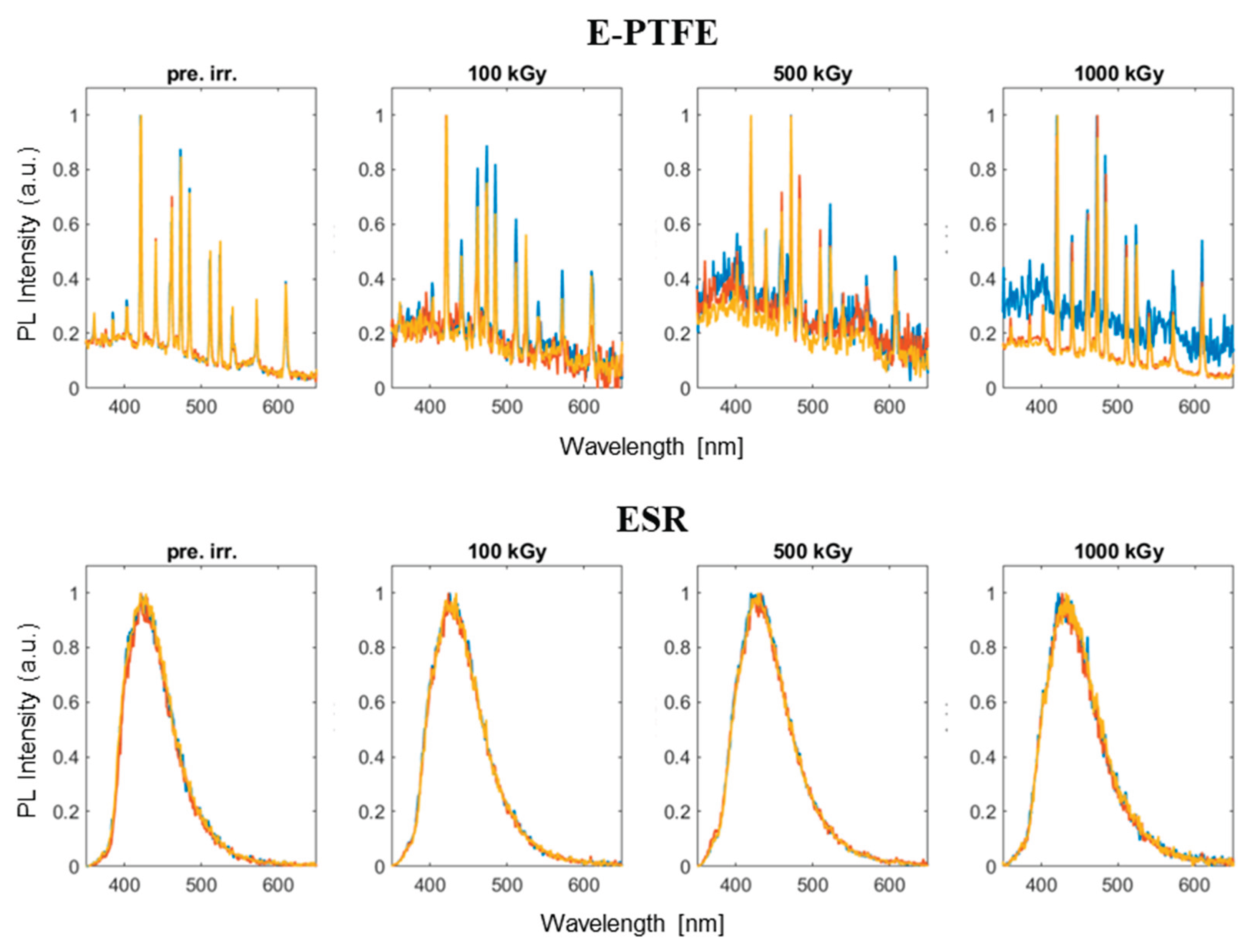
Figure 3.
Variation of the FWHM as a function of the absorbed dose for each sample type.
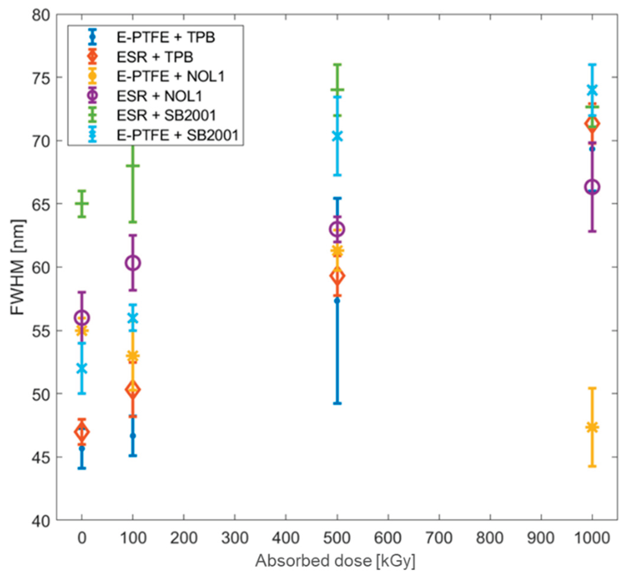
Figure 4.
Normalized emission spectra of E-PTFE (top) and ESR (bottom) substrates, obtained using an excitation wavelength of 250 ± 0.5 nm, before and after neutron irradiation. The three distinct colors (yellow, orange and blue) represent three independent measurements performed on the same sample.
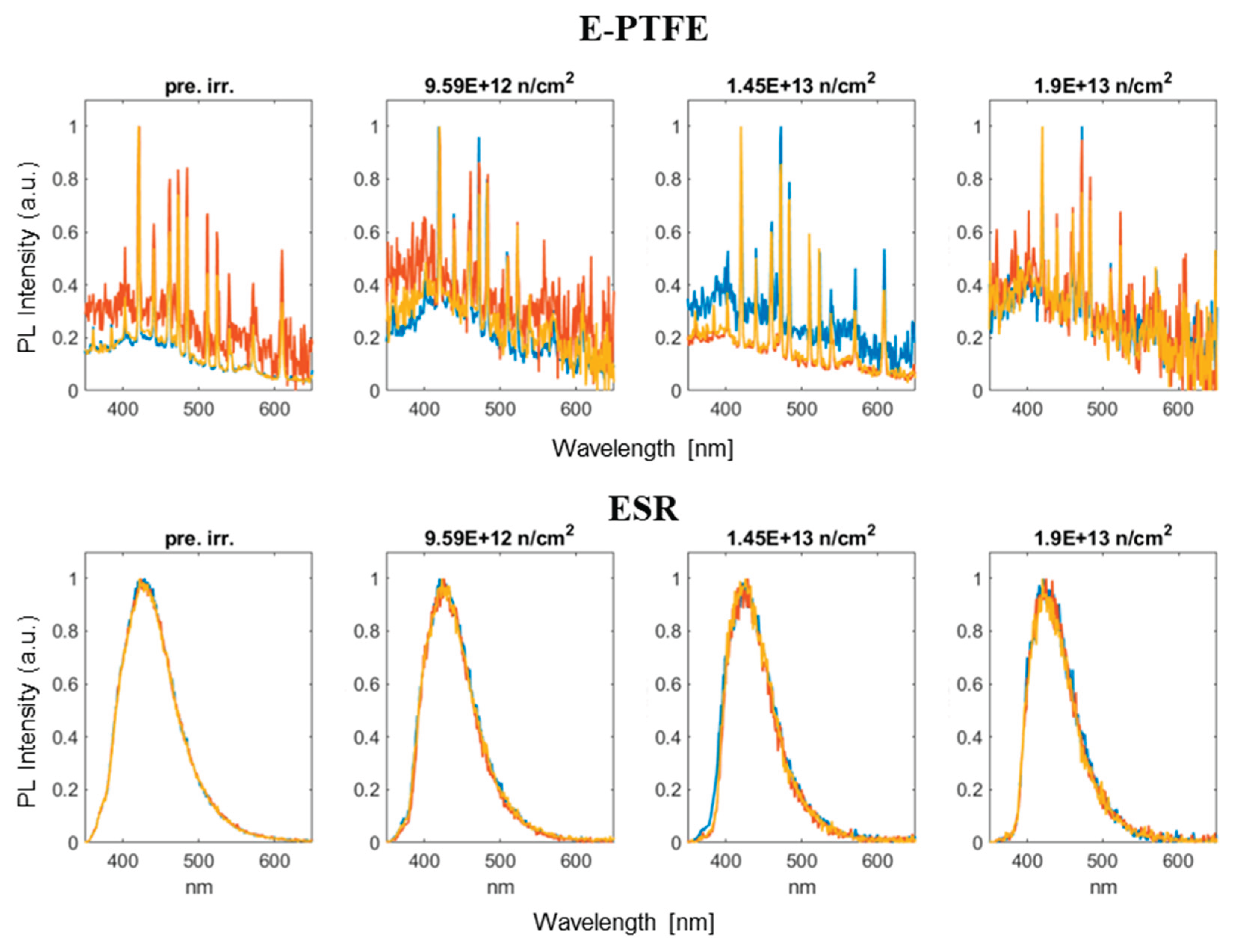
Figure 5.
FWHM evolution post neutron irradiation as a function of neutron fluence level.
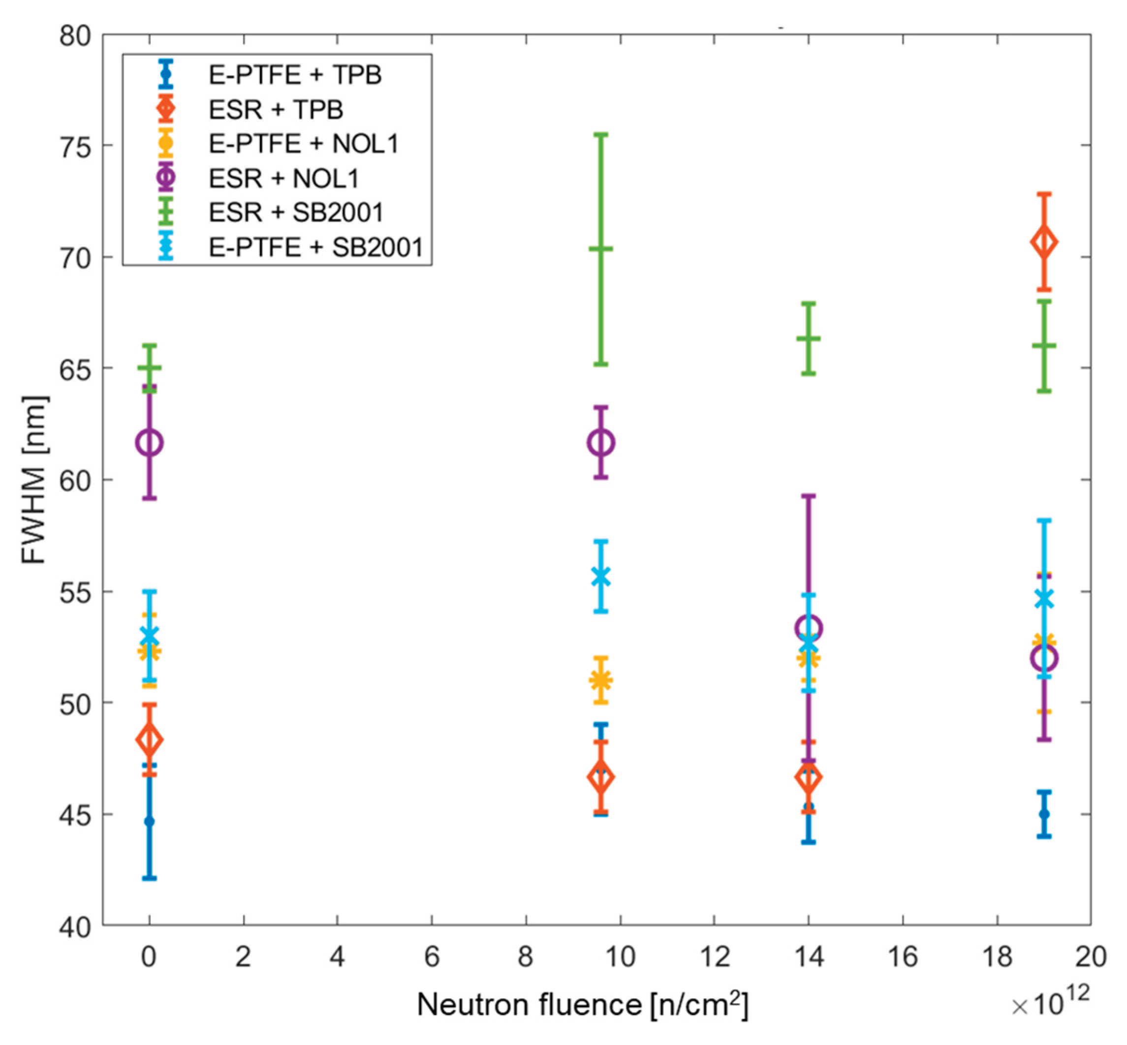
Figure 6.
Reflectance spectra of E-PTFE and ESR substrates before and after irradiation. Before irradiation the reflectance values at 425 nm of E-PTFE and ESR were 98.9% and 97.2%, respectively.
Figure 6.
Reflectance spectra of E-PTFE and ESR substrates before and after irradiation. Before irradiation the reflectance values at 425 nm of E-PTFE and ESR were 98.9% and 97.2%, respectively.
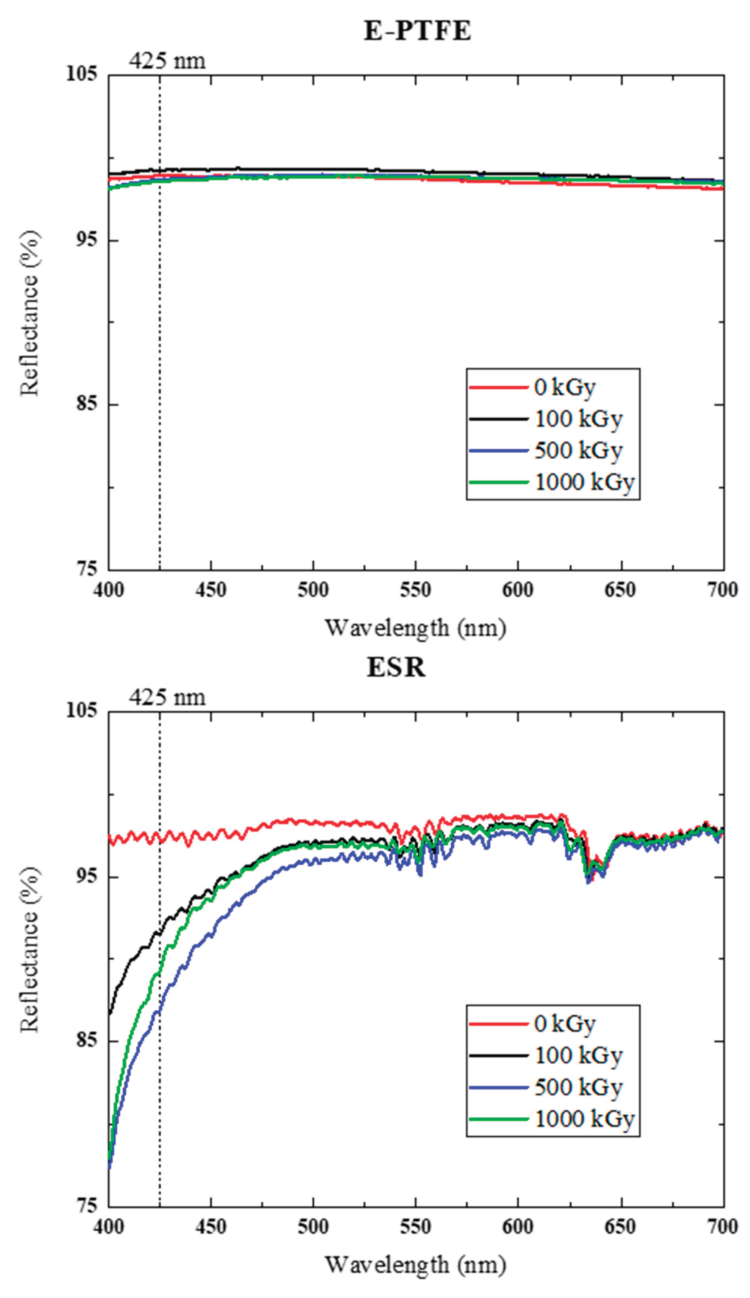
Figure 7.
Reflectance spectra of bulk E-PTFE and ESR substrates after neutron irradiation. Before irradiation the reflectance value at 425 nm of E-PTFE and ESR were 98.9% and 97.2%, respectively.
Figure 7.
Reflectance spectra of bulk E-PTFE and ESR substrates after neutron irradiation. Before irradiation the reflectance value at 425 nm of E-PTFE and ESR were 98.9% and 97.2%, respectively.
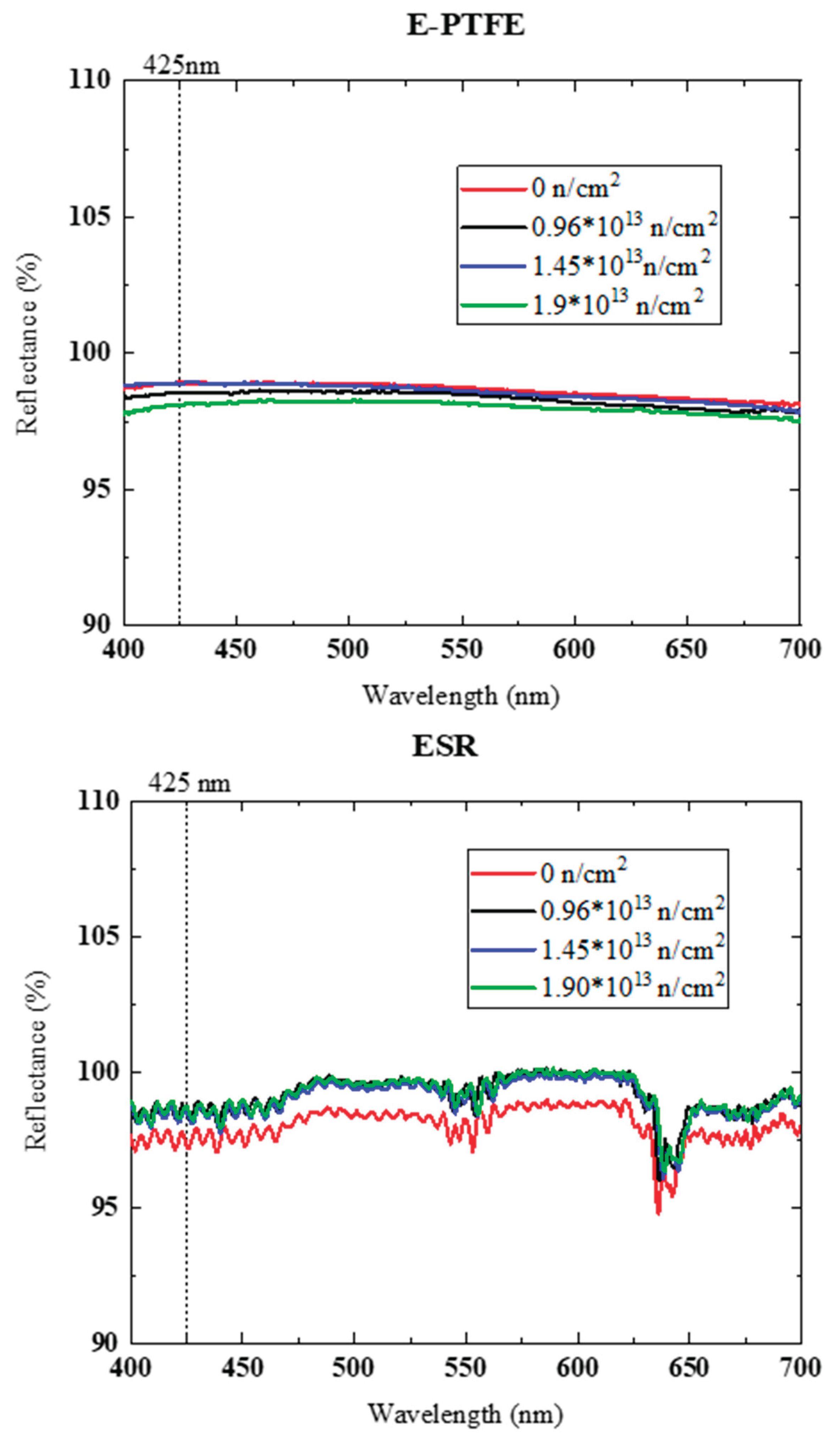
Table 1.
Sample compositions and deposition methods.
| Reflective substrate | WLS Material | Deposition Method |
|---|---|---|
| E-PTFE | TPB | Evaporation |
| ESR | TPB | Evaporation |
| E-PTFE | NOL1 | Liquid coating |
| ESR | NOL1 | Liquid coating |
| E-PTFE | SB2001 | Spray coating |
| ESR | SB2001 | Spray coating |
Table 2.
Spectrofluorometer settings for PL measurements.
| Parameter | Value |
|---|---|
| Excitation λ [nm] | 250 |
| Emission range [nm] | 350 – 650 |
| Step [nm] | 1.0 |
| Dwell time [s] | 0.1 |
| Lamp | Xe |
| Scan slit [mm] | 1.0 |
| Emission slit [mm] | 2.0 |
Table 3.
FWHM of the emission spectra before irradiation and ΔFWHM (nm) of the emission spectra with respect to 0 kGy for increasing absorbed gamma doses. Uncertainties are propagated from original FWHM error values.
Table 3.
FWHM of the emission spectra before irradiation and ΔFWHM (nm) of the emission spectra with respect to 0 kGy for increasing absorbed gamma doses. Uncertainties are propagated from original FWHM error values.
| Sample | FWHM @ 0 kGy (nm) |
ΔFWHM @ 100 kGy (nm) |
ΔFWHM @ 500 kGy (nm) |
ΔFWHM @ 1000 kGy (nm) |
|---|---|---|---|---|
| E-PTFE+TPB (evaporation) |
45.7 ± 1.6 | +1.0 ± 2.3 | +11.6 ± 8.2 | +23.6 ± 3.6 |
| ESR+TPB (evaporation) |
47.0 ± 1.0 | +3.3 ± 2.4 | +12.3 ± 1.9 | +24.3 ± 1.9 |
| E-PTFE+NOL1 (liquid coating) |
55.0 ± 1.0 | -2.0 ± 2.9 | +6.3 ± 1.9 | -7.7 ± 3.2 |
| ESR+NOL1 (liquid coating) |
56.0 ± 2.0 | +4.3 ± 3.0 | +7.0 ± 2.2 | +10.3 ± 4.0 |
| E-PTFE+SB2001 (spray coating) |
52.0 ± 2.0 | +4.0 ± 2.2 | +18.3 ± 3.7 | +22.0 ± 2.8 |
| ESR+SB2001 (spray coating) |
65.0 ± 1.0 | +3.0 ± 4.6 | +9.0 ± 2.2 | +7.7 ± 1.9 |
Table 4.
FWHM of the emission spectra before irradiation and ΔFWHM (nm) of the emission spectra with respect to the not irradiated sample for increasing neutron fluence level. Uncertainties are propagated from original FWHM error values.
Table 4.
FWHM of the emission spectra before irradiation and ΔFWHM (nm) of the emission spectra with respect to the not irradiated sample for increasing neutron fluence level. Uncertainties are propagated from original FWHM error values.
| Sample | FWHM @ 0 n/cm² (nm) |
ΔFWHM @ 9.59×10¹³ n/cm² (nm) |
ΔFWHM @ 1.45×10¹³ n/cm² (nm) |
ΔFWHM @ 1.9×10¹³ n/cm² (nm) |
|---|---|---|---|---|
| E-PTFE+TPB (evaporation) |
44.7 ± 2.5 | +2.3 ± 3.2 | +0.6 ± 2.9 | +0.3 ± 2.7 |
| ESR+TPB (evaporation) |
48.3 ± 1.6 | -1.6 ± 2.3 | -1.6 ± 2.3 | +22.4 ± 2.7 |
| E-PTFE+NOL1 (liquid coating) |
52.3 ± 1.6 | -1.3 ± 1.9 | -0.3 ± 1.9 | +0.4 ± 3.4 |
| ESR+NOL1 (liquid coating) |
61.7 ± 2.5 | 0.0 ± 3.0 | -8.4 ± 6.4 | -9.7 ± 4.3 |
| E-PTFE+SB2001 (spray coating) |
53.0 ± 2.0 | +2.7 ± 2.6 | -0.3 ± 3.0 | +1.7 ± 4.0 |
| ESR+SB2001 (spray coating) |
65.0 ± 1.0 | +5.3 ± 5.3 | +1.3 ± 1.4 | +1.0 ± 2.2 |
Table 6.
Reflectance values R (%) at 425 nm before irradiation and corresponding ΔR (%) variations relative to the not irradiated sample, for increasing neutron fluence levels. Measurement uncertainty: ± 2%.
Table 6.
Reflectance values R (%) at 425 nm before irradiation and corresponding ΔR (%) variations relative to the not irradiated sample, for increasing neutron fluence levels. Measurement uncertainty: ± 2%.
| Sample | R (%) @425 nm 0 n/cm2 |
ΔR (%) @425 nm 0.96 1013 n/cm2 |
ΔR (%) @425 nm 1.45 1013 n/cm2 |
ΔR (%) @425 nm 1.9 1013 n/cm2 |
|---|---|---|---|---|
| Substrate | ||||
| E-PTFE | 98.92 | -0.38 | -0.04 | -0.81 |
| ESR | 97.20 | 1.19 | 1.40 | 1.52 |
| WLS/substrate system | ||||
| E-PTFE+TPB (evaporation) |
98.06 | -2.04 | -2.30 | -2.19 |
| ESR+TPB (evaporation) |
95.00 | -0.09 | -1.33 | -0.94 |
| E-PTFE+NOL1 (liquid coating) |
97.84 | 0.29 | -1.07 | -1.07 |
| ESR+NOL1 (liquid coating) |
97.08 | 0.90 | 0.57 | 1.05 |
| E-PTFE+SB2001 (spray coating) |
97.84 | -15.92 | -16.13 | -16.66 |
| ESR+SB2001 (spray coating) |
87.15 | -2.38 | -2.75 | -2.96 |
Disclaimer/Publisher’s Note: The statements, opinions and data contained in all publications are solely those of the individual author(s) and contributor(s) and not of MDPI and/or the editor(s). MDPI and/or the editor(s) disclaim responsibility for any injury to people or property resulting from any ideas, methods, instructions or products referred to in the content. |
© 2025 by the authors. Licensee MDPI, Basel, Switzerland. This article is an open access article distributed under the terms and conditions of the Creative Commons Attribution (CC BY) license (http://creativecommons.org/licenses/by/4.0/).
Copyright: This open access article is published under a Creative Commons CC BY 4.0 license, which permit the free download, distribution, and reuse, provided that the author and preprint are cited in any reuse.


