
Submitted:
14 October 2025
Posted:
15 October 2025
You are already at the latest version
Abstract
The interaction of an ultra-short, high-power laser pulse with a solid target, in the so-called Target Normal Sheath Acceleration (TNSA) configuration, produces particles in the MeV range. Fast electrons can escape from the target after the interaction, inducing electrostatic fields on the order of TV/m close to the target surface. These fields accelerate MeV protons and heavy ions at the rear of the target, allowing them to escape. The complete process is difficult to probe, as it occurs on the sub-ps timescale. At the INFN-LNF SPARC_LAB test facility, single-shot diagnostics such as the Electro-Optical Sampling (EOS) are being developed and tested for time-resolved direct measurements of the produced electrons and associated longitudinal electric fields. Electrons are the core of the process, and their properties determine the following production of positive charge particles and electromagnetic radiation. Different target geometries and materials are being investigated to analyze the enhancement of fast electron emission and the correlation with positive charge production. Simultaneous observations of electron and proton beams have been performed using two diagnostic lines, the EOS for electrons and a time-of-flight (TOF) detector for protons. This work provides an overview of the previous experiments performed at SPARC_LAB dedicated to the TNSA characterization.
Keywords:
particle accelerator
; beam diagnostics
; laser diagnostics
; plasma diagnostics
; TNSA
1. Introduction
Nowadays, high-power, ultra-short laser systems—reaching powers up to the petawatt (PW) level—are available via Chirped Pulse Amplification (CPA) technology [1]. These systems are employed in a wide range of experimental fields, including materials science, laboratory astrophysics [2], and particle acceleration [3,4,5,6]. In particular, the interaction between an ultra-short (fs), ultra-intense () laser pulse and a solid target has enabled the development of proton, electron, and ion sources via the Target Normal Sheath Acceleration (TNSA) mechanism. The ionic particle beams produced exhibit remarkable characteristics that make them ideal for applications such as hadron therapy in cancer treatment. The proton and ion beams generated contain a high number of particles and are accelerated to energies in the multi-MeV range. They have ps-scale durations, low emittance, and are highly laminar. Their production is closely linked to the electrons accelerated during the initial stages of the TNSA.
The process involves the interaction of the laser pulse with the target, as a thin foil, from which some electrons are directly accelerated. These so-called "hot" electrons are generated at the front surface and propagate into the target bulk, attempting to escape from the rear side into the vacuum. Among them, the most energetic manage to escape (fast electrons), leaving behind an unbalanced positive charge on the target, which generates a strong quasi-static electric potential (TV/m), responsible for ionization of atoms at the target back side. This leads to the ion acceleration to energies on the order of tens of MeV [7]. The electric field also confines the remaining part of the electronic cloud to the target rear surface at a distance of the order of the Debye length [8].
The mechanism is complex and involves the generation of electromagnetic pulses (EMPs) [9]. The spectrum of this radiation depends on the laser intensity [10] and consists of two components. The first one is in the GHz domain [11,12] with a temporal duration of ns, and it originates from the neutralization of return currents flowing within the target to balance the induced positive charge. The second component is an ultra-short (tens of ps) THz pulse [13,14], which is linked to the current associated with fast electrons. These phenomena occur on extremely short timescales, making experimental investigation particularly challenging.
The temporal evolution of electrons and electromagnetic fields generated during the interaction can be directly investigated using Electro-Optic Sampling (EOS) diagnostics. This was demonstrated at the SPARC_LAB test facility of INFN-LNF [15], where, for the first time, single-shot measurements with femtosecond resolution were performed on both fast electrons and electromagnetic pulses produced by the interaction of the 200 TW FLAME laser system [16] with a solid target. This diagnostic enabled a detailed investigation of the relationship between the target geometry and key properties of the generated electron bunches, such as charge, energy, and duration.
For proton beam characterization, a diamond-based time-of-flight (TOF) detector was implemented. All measurements were also analyzed as a function of the available laser beam parameters. In this review, we provide the experimental results carried out at SPARC_LAB regarding the fast electron characterization, the electron-proton beam correlation and the EMPs detection.
2. Experimental Setup
The experiments were performed at the SPARC_LAB test facility with the FLAME laser. The system is a 200 TW Ti:Sapphire laser based on Chirped Pulse Amplification (CPA) technology, delivering up to 6 J energy and 30 fs at 800 nm (at the final cryo-amplifier output). The beam is transported to the interaction chamber after temporal compression and optimized using two acousto-optic modulators (Fastlite MAZZLER and DAZZLER), with a total energy transport efficiency of 70%. This system section operates in a high-vacuum environment ( mbar) to prevent self-focusing effects and to minimize contamination during the experiments.
The setup in the experimental area is shown in Figure 1, the laser beam is focused on the target to reach high interaction intensities using a gold-coated, 15-degree Off-Axis Parabolic (OAP) mirror (f/10) with a focal length of 1 m. In these experiments, the laser spot is optimized by a Shack-Hartmann wavefront sensor and by a deformable mirror to remove aberrations after the CPA chain and to have the maximum energy in the laser focal spot. The latter had a radius of 25 m.
Different solid targets were tested, varying thickness, geometry, and materials to investigate their effect on the energy gain of the accelerated ions. The main configuration employed a stainless steel sharp target such as a commercial razor blade [17]. Subsequently, planar and tipped targets were tested, including aluminum foil and a needle-shaped tip [18]. A sapphire target was also tested [19], it was 400 m thick, uncoated and, with a resistivity ranging from at to at .
In the laser system, the probe beam is split from the beamline after the second amplifier, ensuring a jitter-free synchronization, to operate at low energy (some tens of mJ) and with a temporal compression down to 35-40 fs. It has a transverse spot size of 6 mm Full Width Half Maximum (FWHM), and it follows a specific transport line to the experimental area.
The two beams are synchronized in the interaction chamber via an optical delay line by means of an -cut BBO crystal. The latter is installed on a holder together with the ZnTe crystal, 1 mm above the target. The synchronization is achieved by looking for the second harmonic generation (SHG) signal produced in the crystal. The light emitted from the SHG determines the overlap time which is our reference time. After that, the delay line is adjusted to synchronize the probe beam with respect to the emitted electrons or electromagnetic pulses to generate a detectable signal on the CCD camera. The diagnostics of the interaction chamber (Figure 1) are described in detail in the following section.
3. Diagnostics
3.1. EOS Detector
The Electro-Optic Sampling (EOS) is one of the diagnostic techniques implemented during the experimental campaigns [17,18,19,20,21,22,23] on laser-solid target interactions at SPARC_LAB.
It is a single-shot diagnostic that employs a ZnTe 500 m-thick crystal to obtain time-resolved measurements of the properties of fast electrons produced during the interaction, enabling the investigation of the temporal evolution of the TNSA process. The EOS resolution is determined by the probe beam duration, the type of electro-optic crystal, and its thickness; for our experimental conditions, the system achieves a temporal resolution of sub-100 fs.
The EOS diagnostic has enabled the first direct and time-resolved observation of the emitted fast electrons.
The setup is shown in Figure 2: the probe beam from the FLAME laser system impinges on the crystal at an angle of with a spot diameter of approximately 6 mm (FWHM). Thanks to the spatial encoding technique [24], the temporal profile of the electrons emitted from the target is mapped onto the transverse profile of the laser beam. The equation that relates the longitudinal coordinate of the bunch to the transverse coordinate of the laser is , and a temporal window of 10 ps was obtained under these conditions.
The electric field generated by the electron bunch induces a localized birefringence in the crystal, which in turn induces a modulation in the polarization of the probe beam. If the probe laser is linearly polarized, the polarization is rotated by an angle where is the electro-optic coefficient and d is the crystal thickness. A polarizer, placed downstream of the crystal and oriented orthogonally to the initial polarization of the probe, converts this polarization modulation into intensity variation that can be easily detected by a CCD camera. In the absence of EO-induced phase retardation, no light is transmitted through the analyzer.
This approach allows for a direct mapping of the electric field generated by the electrons, which is proportional to the bunch charge. The intensity of the resulting signal can therefore be used to estimate the charge. Additionally, the signal width corresponds to the temporal duration of the electron bunch, also providing a temporal length direct measurement.
Moreover, the EOS diagnostics can also be employed as a Time-Of-Flight (TOF) [24,25] detector by measuring the temporal delay of the signal with respect to a known reference. Then from the particle time of flight the particle velocity can be determined and consequently its energy with c the light speed and the electron rest mass in eV units, enabling a time-resolved energy measurement. This provides a distinct advantage over conventional, time-integrated diagnostics such as magnetic spectrometers.
This diagnostic was also used to detect the electromagnetic pulses generated during the laser–solid target interaction. The figure shows the resulting encoding process for this measurement, as recorded by the CCD placed at the end of the probe beam line. By varying the delay of the probe beam with respect to the emission of the pulses, it is of course possible to reconstruct their temporal evolution. Also in this case, the local birefringence of the crystal changes as the electromagnetic field passes through. Section 4.2 provides the details of the diagnostic setup for this type of measurement and the related analysis.
3.2. Time-Of-Flight Detector
The Time-Of-Flight (TOF) diamond detector is another diagnostic tool used in experimental campaigns for detecting the accelerated ion and proton beams produced during the TNSA process.
This device, whose structure is shown in Figure 3, has a surface and interdigital geometry with multiple electrodes in the active area. These electrodes are spaced by 20 m, allowing us to achieve a temporal resolution of 800 ps, which is higher than that of standard commercial detectors. In addition to excellent temporal resolution, it provides a high energy resolution up to 3% for MeV-range ion bunches at 1 m between the detector and the source. The detector thickness determines the maximum energy measurable. Diamond detectors are insensitive to visible light but can detect particles with energies above the band gap threshold.
The detector is biased at -150 V and equipped with a custom-designed high-frequency bias-tee to separate the direct current (DC) signal from the alternating current (AC) signal, the latter resulting from electron-hole pairs generated by the energy deposited in the diamond by charged particles. The detector is placed inside the interaction chamber and is therefore susceptible to interference from EMPs, which act as a noise source. However, owing to system design and optimization [26,27], EMP coupling with the desired signals is canceled.
4. Experimental Results
4.1. Fast Electrons
The first experimental campaigns conducted at FLAME led to the direct and time-resolved detection of fast electrons [17]. These measurements were performed with sub-picoseconds temporal resolution using EOS diagnostics, which allowed precise characterization of the charge, temporal duration, and mean energy.
In the first experiment, the target was a stainless steel wedged razor blade on which the main laser beam was focused with a maximum energy of 2 J in the interaction chamber. Figure 4 shows a typical single-shot EOS image acquired by the CCD (left), displaying the signal induced by the fast electron bunch. The signal exhibits a curved and non-uniform structure, the first effect is caused by the superposition direction of the signal on the crystal, the latter arises from the non-uniform transverse profile of the probe beam and surface inhomogeneities on the ZnTe crystal.
The EOS signal intensity is proportional to the bunch charge, which was ∼2 nC. The temporal profile was retrieved by performing a line-out along the time axis of the image on the left as shown in Figure 4 (right). The bunch duration is about 500 fs and the plot shows fast electrons temporally bunched with a peak current of about 2 kA.
After this analysis, different target geometries were tested to investigate how the shape of the irradiated surface affects fast electron emission. Previous studies [28,29,30] have shown that structured targets can lead to increased final ion energies, mainly due to enhanced electrostatic field. In our experiment, we aimed to verify whether increasing the curvature of the surface irradiated by the laser results in a higher number of emitted electrons.
4.1.1. Different Target Shapes
Snapshots with the EOS signal for different target shapes are shown in Figure 5.
Two distinct electron bunches are visible in Figure 5 (top-left) for the interaction with a planar target, a 10 m thick aluminum foil. The first bunch carries a charge of approximately 1.2 nC with a mean energy of 7 MeV, while the second bunch, significantly weaker, has a charge of about 0.3 nC and a lower energy of 1 MeV. The mean energy of these electrons was determined by measuring their time of flight to the detector and, the temporal length was retrieved directly from the EOS trace, together with the bunch charge and the electric field. The corresponding longitudinal charge profile of this snapshot is shown in Figure 5 (bottom-left). The temporal delay was measured to be 1.5 ps.
The wedged target was a commercial razor blade and data are shown in Figure 5 (top-center); the first electron bunch (E1) exhibits increased charge, around 2 nC, while maintaining a similar energy of 7 MeV. The second bunch (E2) is 0.3 nC and a delay of 2 ps to the first.
Finally, Figure 5 (top-right) presents the results obtained using a needle tip target. In this configuration, the first bunch reaches a higher energy of 12 MeV and a significant number of particles of 7 nC. The intense electron bunch induces a strong birefringence in the crystal, rotating the probe beam’s polarization by more than . This leads to a distinct orientation of the EOS signal compared to earlier configurations. Here too, a second electron bunch is clearly visible, carrying an estimated charge of about 3 nC.
4.1.2. Different Target Materials
Additional experiments were conducted to characterize fast electron emission from targets with varying material composition and thickness, consistently using the same diagnostic techniques [19,22]. This approach enabled the acquisition of experimental evidence supporting scaling laws that describe the phenomenon as a function of the laser energy incident on the target (from 0.4 J to 4 J) and the target material.
The materials under comparison were stainless steel (wedged metallic target) and sapphire (dielectric). The thicknesses are different: 5 m for the steel and 400 m for the latter. The charge and the peak electric field of the hot electron bunches were retrieved from the EOS signal’s amplitude and spatial extent.
The Figure 6 shows two plots: (a) for the wedged-metallic target and (b) for the dielectric target, displaying the results of the charge values and electric field peak as a function of the laser energy delivered to the target (measured r.m.s. value).
Each point is the average value over 10 shots, with vertical error bars corresponding to the standard deviation. As shown, both parameters exhibit a positive correlation with laser energy, consistent with the expectation that higher intensities enhance charge extraction and thus increase the resulting electric field.
The experimental data were fitted by power functions defined in terms of six free parameters : and where is the laser energy. The results for the metallic target are
and for the dielectric target are
An analytic scaling law derived in [19], based on theoretical models [31,32,33] was used to support our experimental results.
We also retrieved the temporal duration of these fast electron bunches as a function of the laser energy and fitted the data with a power function, as shown in Figure 7. There were three free parameters and the resulting functions are
respectively for the metallic and dielectric target.
The scaling laws describing the bunch temporal duration are quite different: with the metallic target, the temporal length decreases more significantly as the laser energy increases compared to the dielectric target. In general, at lower laser energy, the electrons are less relativistic, and the temporal duration increases due to the velocity spread of the bunch. Additionally, the increasing potential acts as a velocity filtering. Conversely, at higher laser energies, relativistic electrons are emitted with a smaller velocity spread, resulting in a temporally shorter bunch, and the strong decelerating potential continues to act as a high-velocity pass filter.
4.2. Electromagnetic Pulses
In addition to electron and ion bunches, the high-intensity laser–target interaction also generates electromagnetic pulses (EMPs). Studying the characteristics of these pulses provides a more comprehensive understanding of the interaction process. At FLAME, it was possible to detect and analyze these EMPs using EOS diagnostics, including the temporal duration, peak electric field, and time evolution of the emitted pulses [20].
The target was a commercial blade with a varying thickness: 0.7 m at the edge and 6 m at the center. The same EOS encoding method used for fast electron detection was applied to analyze the EMP signals, but in this case, the probe laser is systematically delayed or advanced relative to the EMPs signal to reconstruct its temporal profile. Figure 8 shows a schematic side and top view of the setup for the EMPs detection.
In the acquired EOS images (Figure 9), the probe laser travels through the crystal from left to right; the latter is always 1 mm downstream and above the target. The horizontal extent of the detected signal reflects the physical size of the radiation source on the target. By increasing the delay of the probe relative to the EMP, the signal shifts to the left side of the snapshot, revealing the temporal evolution of the field and providing information on the expansion velocity of the emitting area on the target surface.
The vertical width corresponds instead to the temporal duration of the pulse, which, in this experimental configuration of 2 J laser pulse on 0.7 m target, was (6 ± 1) ps. In Figure 9 there are different shots incrementing probe delays of 2.5 ps, where the x-axis is the probe arrival time at the crystal associated to each pixel.
As the delay increases, the signal intensity varies, reflecting the changing charge density on the target, the source of the EMPs. However, the temporal duration of the individual pulses remains constant throughout the observed time window of 15 ps. Beyond this time interval, the EMPs become too weak to be detected by the EOS detector. the observed propagation velocity was (0.94 ± 0.03)c where c is the light velocity.
Figure 10 (left) shows the field amplitude as a function of the laser energy focused on the target (10%, 50%, 100%). An increase in the field strength is observed with increasing laser energy, reaching a maximum of 0.8 MV/m. The temporal duration also changes, ranging from 5 ps to 7.1 ps (FWHM). The plot (right) presents the peak field as a function of laser energy described by a power law . The field enhancement is relatively modest compared to the corresponding increase in laser energy. From this analysis, it is also possible to extract information about the number of electrons emitted from the target. If we define as the charge of the fast electrons emitted from the target, we have the surface charge density on the target based on the positive charge induced after the electron emission with the laser spot size. Therefore, the electric field associated with this charge density is defined as .
To quantify these quantities and compare their values, several shots were performed, allowing simultaneous and direct detection, via EOS diagnostics, of both the emitted electrons and EMPs.
In Figure 11(left), the laser (maximum energy of 2 J) is focused on the target edge. The diagnostics detected for the first time both the EMP signal and the electron bunches, specifically, two distinct bunches with different energy and charge. In the first bunch, there are the fastest electrons, while the second, with lower energy and reduced charge, is mainly attributed to plasma expansion and charge recycling occurring on the target after the interaction.
As described in the previous section, we can determine the charge and energy of these bunches, The first bunch carries 2 nC with a mean energy of 7 MeV and a temporal duration of 400 ps (FWHM). The second component reaches the crystal with a 2 ps delay relative to the first and carries 0.3 nC of charge with 0.6 MeV of energy.
When instead the laser is focused on the bulk of the target of 6 m-thick at 1 J and the probe laser is delayed of 4 ps, the EMP signal shift to the left and the fastest bunch is no longer visible because it falls outside the diagnostics time window (see Figure 11 (right)). Moreover, the temporal duration of the EMP increases since changing the target thickness and laser energy, the amount of energy involved in the interaction changes. This clearly demonstrates that the process dynamics is linked to the laser energy deposition.
Considering the earlier discussion about the electric filed value from the emitted electrons number: if we consider the ultrafast bunch with 2 nC of charge and a laser spot size of 12 m at , we obtain an electric filed associated with the surface charge density on the target of 0.6 MV/m, in agreement with the experimental results.
4.3. Proton Beams
The diamond TOF detector was used to characterize ion beams accelerated by the quasi-static electric field at the rear side of the target. This diagnostic system allowed the retrieval of the proton bunches’ kinetic energy.
The experimental setup is described in Section 2. A typical signal acquired by the oscilloscope is shown in Figure 12, in this experimental case, the laser pulse is focused on a 5-m-thick stainless steel target with an intensity of . Two distinct peaks can be observed in the picture, occurring at different times: the first, less intense, is associated with X-rays and fast electrons, while the second, more visible, corresponds to the proton bunch.
The time delay between the two signals is defined as and it’s measured with respect to the first peak rising front. Therefore, the proton beam energy is calculated by where is the ion rest mass, is the Lorentz relativistic factor. The factor is defined by the distance between the TOF detector and the target 1 m and the time of flight of the X-rays from the source to the detector 3.3 ns.
To shield the TOF from electromagnetic radiation and target debris, a 10-micron-thick Al foil was placed in front of it. The energy attenuation introduced by the filter was evaluated through MonteCarlo simulations using the SRIM code, as reported in [21].
Under these experimental conditions, the maximum proton energy measured was 1.37 MeV.
4.4. Electron-Proton Beams Correlation
Since ion generation and acceleration are closely linked to electron beam production in the early stages of the TNSA mechanism, analyzing the correlation between these two particle types is of fundamental importance.
For this reason, we performed simultaneous time-resolved measurements of both protons and electrons, using the available diagnostics [21,23,34].
First, parametric scans were performed by varying the laser pulse duration (from 30 to 300 fs) and the focal spot size (diameter at from 30 to 120 ), while keeping the laser energy constant at 2 J on a 10-micron-thick Al foil as target [34]. Then the laser was set at 30 fs with a waist of 15 m, changing the energy on the target from (0.5 to 2 J). The goal was to measure the evolution of the maximum proton energy and the properties of the fast electron bunch (charge and temporal duration). Some previous works reported a scaling law for the maximum proton energy [35,36,37] and for our target thickness and laser pulse duration the expected values are of few MeV.
In Figure 13, we present some experimental results. On the left, we show the measured electron bunch charge and duration, along with the maximum proton energy, as a function of the laser pulse duration. On the right, the same quantities are plotted with respect to the laser focal spot size.
As expected, the characteristics of the fast electrons depend on the laser intensity on the target, which in turn varies with both the pulse duration and the focal spot area. Furthermore, as already reported in previous works [35], the proton energy shows weak dependence on the laser pulse duration, while being more strongly influenced by the spot size and the total energy delivered to the target.
Focusing first on the temporal scan (A): the electron bunch charge decreases as the pulse duration increases, while the bunch duration increases linearly. This behavior is consistent with the reduced intensity for longer pulses, leading to less energetic electrons with broader temporal distribution. In this configuration, the maximum proton energy follows a power-law scaling as
The right-hand plot (B) reveals a different behavior for the laser spot size scan: both electron charge and proton energy decrease exponentially with increasing , whereas the still follows a linear increase.
In this case, the maximum proton energy can be described as a function of the laser intensity by the following equation
Considering the laser intensity definition , the proton energy behaviour can be expressed as . Overall, the maximum measured proton energy was (2.9 ± 0.1) MeV with an electron bunch carrying ∼ (1.8 ± 0.4) nC.
The correlation between electrons and protons was also analyzed as a function of the laser energy, keeping the pulse duration and spot size constant. The results were supported by numerical simulation carried out with the Electron Ballistic Code (EBC [22]). Figure 14 (top) shows the trend of the electron charge and the maximum proton energy as the laser energy increases with the simulation results. The results agree with previous works [35,38,39] and the following relation was obtained
The plot in Figure 14(bottom) presents the experimental data for the electron bunch duration and the proton energy, again as a function of and compared with simulations. The following function describes the evolution of
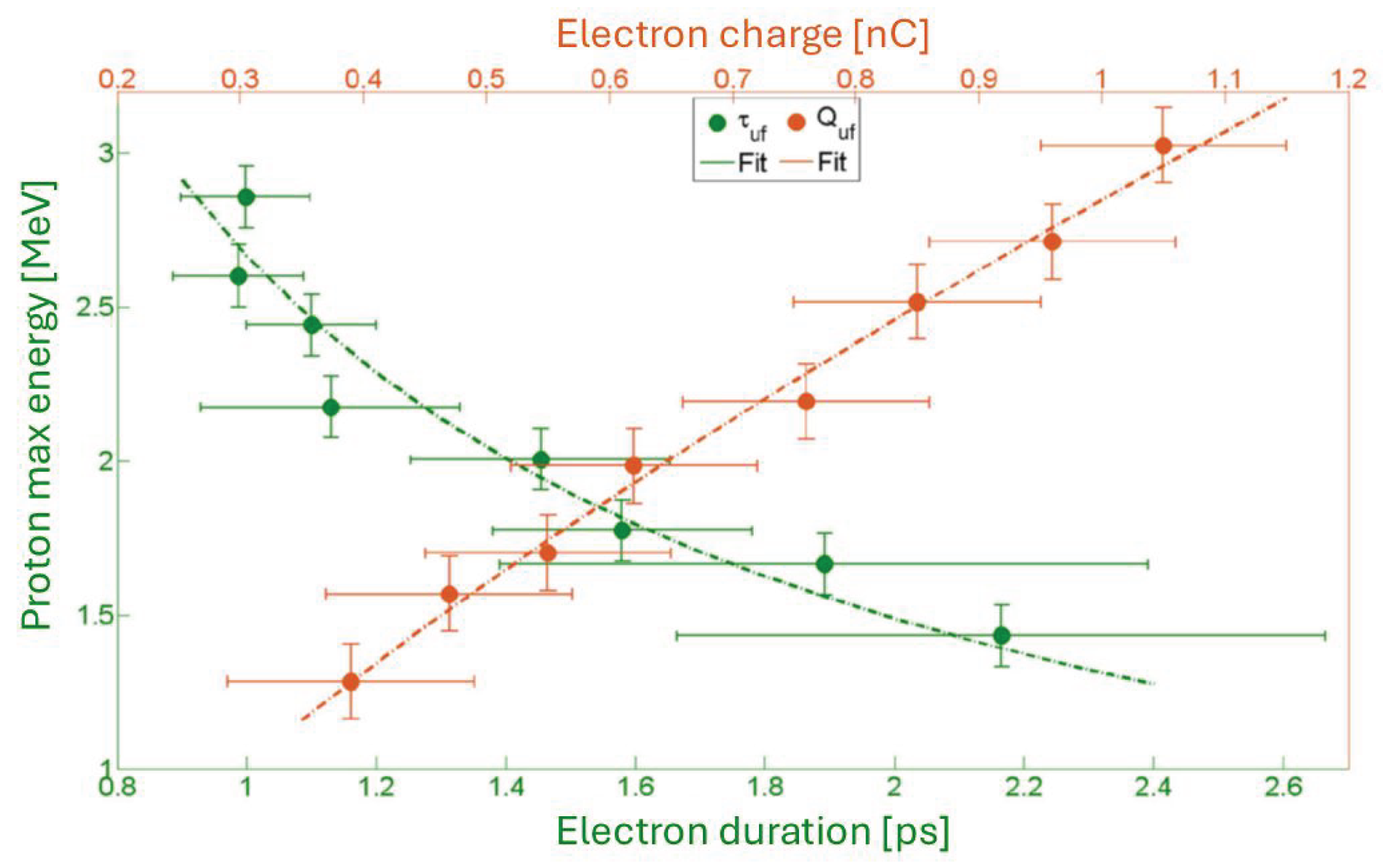
In the last Figure 15, it’s shown the maximum proton energy as a function of the fast electron charge (orange data) and duration (green data), which can be described by
5. Conclusions
This paper reviews the experiments carried out at the SPARC_LAB facility at the National Laboratories of Frascati-INFN, investigating laser-solid target interactions in the TNSA configuration. The diagnostics used to characterize the process are initially presented in detail, with particular emphasis on the detection of electron bunches, electromagnetic pulses and accelerated proton beams in different experimental setups.
The EOS diagnostics enabled, for the first time, the direct, time-resolved and, simultaneous single-shot detection of both electrons and EMPs, with unprecedented resolution better than 100 fs. The electron beam properties were analyzed for different target shapes and materials, as well as for various laser parameters, allowing the reconstruction of the target charging dynamics. These results demonstrated an increase in the charge and energy of fast electrons for sharp-structured targets, and the production of more charged and shorter electron bunches as the laser energy increased.
The analysis of the EMPs proved to be a complementary diagnostic to electron and ion measurements, offering deeper insight into the TNSA acceleration mechanism.
In the last experimental campaigns, the correlation between the maximum energy of the accelerated protons and the fast electrons was investigated. The results showed that the proton energy increases with the charge extracted by fast electrons, as a direct consequence of a stronger potential on the target’s rear surface. Therefore, the initial conditions, such as the laser parameters and target geometries, determine the proton acceleration process. This analysis demonstrated that it is possible to predict the proton energy spectrum based on the characterization of fast electrons. All the analysis were supported by numerical simulations.
Author Contributions
Conceptualization and methodology, F.B., M.G., R.P. and A.Z.; software, M.P.A, A.C. and F.B.; validation and formal analysis, A.C., F.B., M.G., R.P., M.C., F.C. and M.S.; investigation, F.B., M.G. and R.P.; resources, F.C., M.C., M.S., C.V.; data curation, M.P.A., F.B., G.C., A.Cu., M.G., R.P., and A.Z.; writing—review and editing, All authors; supervision, A.Ci., A.Z., M.F.; project administration, A.Ci., A.Z., M.F.; funding acquisition, M.F. All authors have read and agreed to the published version of the manuscript.
Funding
This work has been partially supported by the EU Commission in the Seventh Framework Program, Grant Agreement 312453-EuCARD-2 and the Italian Research Minister in the framework of FIRB - Fondo per gli Investimenti della Ricerca di Base, Project n. RBFR12NK5K. The work of one of us (A.Z.) was partially supported by BSF foundation. This work was also supported by the European Union‘s Horizon 2020 research and innovation programme under grant agreement No. 653782.
Institutional Review Board Statement
Not applicable
Data Availability Statement
No new data were created for the presented review paper.
Conflicts of Interest
The authors declare no conflicts of interest.
References
- Strickland, D.; Mourou, G. Compression of amplified chirped optical pulses. Opt. Commun. 1985, 55, 447–449. [Google Scholar] [CrossRef]
- Remington, B.; Arnett, D.; Paul, R.; Drake; Takabe, H. Modeling Astrophysical Phenomena in the Laboratory with Intense Lasers. Science 1999, 284, 1488–1493. [Google Scholar] [CrossRef]
- Esarey, E.; Schroeder, C.B.; Leemans, W.P. Physics of laser-driven plasma-based electron accelerators. Rev. Mod. Phys. 2009, 81, 1229–1285. [Google Scholar] [CrossRef]
- Ledingham, K.; Galster, W. Laser-driven particle and photon beams and some applications. New J. Phys. 2010, 12, 045005. [Google Scholar] [CrossRef]
- Bartal, T.; Foord, M.; Bellei, C.; Key, M.; Flippo, K.; Gaillard, S.; Offermann, D.; Patel, P.; Jarrott, L.; Higginson, D.; et al. Focusing of short-pulse high-intensity laser-accelerated proton beams. Nat. Phys. 2011, 8, 139–142. [Google Scholar] [CrossRef]
- Macchi, A.; Borghesi, M.; Passoni, M. Ion acceleration by superintense laser-plasma interaction. Rev. Mod. Phys. 2013, 85, 751–793. [Google Scholar] [CrossRef]
- Wagner, F.; Deppert, O.; Brabetz, C.; Fiala, P.; Kleinschmidt, A.; Poth, P.; Schanz, V.A.; Tebartz, A.; Zielbauer, B.; Roth, M.; et al. Maximum Proton Energy above 85 MeV from the Relativistic Interaction of Laser Pulses with Micrometer Thick CH2 Targets. Phys. Rev. Lett. 2016, 116, 205002. [Google Scholar] [CrossRef]
- Badziak, J.; Głowacz, S.; Jablonski, S.; Parys, P.; Wołowski, J.; Hora, H.; Krasa, J.; Láska, L.; Rohlena, K. Production of ultrahigh ion current densities at skin-layer subrelativistic laser–plasma interaction. Plasma Phys. Control. Fusion 2004, 46, B541. [Google Scholar] [CrossRef]
- Hamster, H.; Sullivan, A.; Gordon, S.; White, W.; Falcone, R. Subpicosecond, electromagnetic pulses from intense laser-plasma interaction. Phys. Rev. Lett. 1993, 71, 2725–2728. [Google Scholar] [CrossRef]
- Nelissen, K.; Liszi, M.; De Marco, M.; Ospina, V.; Drotár, I.; Gatti, G.; Kamperidis, C.; Volpe, L. Characterisation and modelling of ultrashort laser-driven electromagnetic pulses. Sci. Rep. 2020, 10, 3108. [Google Scholar] [CrossRef]
- Poyé, A.; Hulin, S.; Bailly-Grandvaux, M.; Dubois, J.-L.; Ribolzi, J.; Raffestin, D.; Bardon, M.; Lubrano-Lavaderci, F.; D’Humières, E.; Santos, J.J.; et al. Physics of giant electromagnetic pulse generation in short-pulse laser experiments. Phys. Rev. E 2015, 91, 043106. [Google Scholar] [CrossRef]
- Consoli, F.; De Angelis, R.; Duvillaret, L.; Andreoli, P.; Cipriani, M.; Cristofari, G.; Giorgio, G.; Ingenito, F.; Verona, C. Time-resolved absolute measurements by electro-optic effect of giant electromagnetic pulses due to laser-plasma interaction in nanosecond regime. Sci. Rep. 2016, 6, 27889. [Google Scholar] [CrossRef]
- Gopal, A.; Herzer, S.; Schmidt, A.; Singh, P.; Reinhard, A.; Ziegler, W.; Brömmel, D.; Karmakar, A.; Gibbon, P.; Dillner, U.; et al. Observation of Gigawatt-Class THz Pulses from a Compact Laser-Driven Particle Accelerator. Phys. Rev. Lett. 2013, 111, 074802. [Google Scholar] [CrossRef] [PubMed]
- Hu, K.; Yi, L. Relativistic terahertz radiation generated by direct-laser-accelerated electrons from laser-foil interactions. Phys. Rev. A 2020, 102, 023530. [Google Scholar] [CrossRef]
- Ferrario, M.; Alesini, D.; Anania, M.; Bacci, A.; Bellaveglia, M.; Bogdanov, O.; Boni, R.; Castellano, M.; Chiadroni, E.; Cianchi, A.; et al. SPARC_LAB present and future. Nucl. Instrum. Methods Phys. Res., Sect. B 2013, 309, 183–188. [Google Scholar] [CrossRef]
- Galletti, M.; Stocchi, F.; Costa, G.; Curcio, A.; Del Giorno, M.; Pompili, R.; Cacciotti, L.; Di Pirro, G.; Dompè, V.; Verra, L.; et al. Overview and Recent Developments of the Frascati Laser for Acceleration and Multidisciplinary Experiments Laser Facility at SPARC_LAB. Appl. Sci. 2024, 14, 8619. [Google Scholar] [CrossRef]
- Pompili, R.; Anania, M.P.; Bisesto, F.; Botton, M.; Castellano, M.; Chiadroni, E.; Cianchi, A.; Curcio, A.; Ferrario, M.; Galletti, M.; et al. Sub-picosecond snapshots of fast electrons from high intensity laser-matter interactions. Opt. Express 2016, 24, 29512–29520. [Google Scholar] [CrossRef]
- Pompili, R.; Anania, M.P.; Bisesto, F.; Botton, M.; Castellano, M.; Chiadroni, E.; Cianchi, A.; Curcio, A.; Ferrario, M.; Galletti, M.; et al. Femtosecond dynamics of energetic electrons in high intensity laser-matter interactions. Sci. Rep. 2016, 6, 35000. [Google Scholar] [CrossRef]
- Galletti, M.; Bisesto, F.G.; Anania, M.P.; Ferrario, M.; Pompili, R.; Poyé, A.; Zigler, A. Time-resolved characterization of ultrafast electrons in intense laser and metallic-dielectric target interaction. Opt. Lett. 2020, 45, 4420–4423. [Google Scholar] [CrossRef]
- Pompili, R.; Anania, M.P.; Bisesto, F.; Botton, M.; Chiadroni, E.; Cianchi, A.; Curcio, A.; Ferrario, M.; Galletti, M.; Henis, Z.; et al. Ultrafast evolution of electric fields from high-intensity laser-matter interactions. Sci. Rep. 2018, 8, 3243. [Google Scholar] [CrossRef]
- Bisesto, F.; Galletti, M.; Anania, M.P.; Ferrario, M.; Pompili, R.; Botton, M.; Zigler, A.; Consoli, F.; Salvadori, M.; Andreoli, P.; et al. Single-shot electrons and protons time-resolved detection from high-intensity laser–solid matter interactions at SPARC_LAB. High Power Laser Sci. Eng. 2019, 7, e53. [Google Scholar] [CrossRef]
- Galletti, M.; Bisesto, F.G.; Anania, M.P.; Ferrario, M.; Pompili, R.; Poyé, A.; Tikhonchuk, V.; Zigler, A. Direct observation of ultrafast electrons generated by high-intensity laser-matter interaction. Appl. Phys. Lett. 2020, 116, 064102. [Google Scholar] [CrossRef]
- Bisesto, F.; Galletti, M.; Anania, M.P.; Costa, G.; Ferrario, M.; Pompili, R.; Zigler, A.; Consoli, F.; Cipriani, M.; Salvadori, M.; et al. Simultaneous observation of ultrafast electron and proton beams in TNSA. High Power Laser Sci. Eng. 2020, 8, e23. [Google Scholar] [CrossRef]
- Cavalieri, A.L. Electro-optic characterization of femtosecond electron bunches. PhD Thesis, The University of Michigan, University, 2025. [Google Scholar]
- Pompili, R.; Anania, M.P.; Bellaveglia, M.; Biagioni, A.; Castorina, G.; Chiadroni, E.; Cianchi, A.; Croia, M.; Di Giovenale, D.; Ferrario, M.; et al. Femtosecond timing-jitter between photo-cathode laser and ultra-short electron bunches by means of hybrid compression. New J. Phys. 2016, 18, 083033. [Google Scholar] [CrossRef]
- De Angelis, R.; Consoli, F.; Verona, C.; Di Giorgio, G.; Andreoli, P.; Cristofari, G.; Cipriani, M.; Ingenito, F.; Marinelli, M.; Verona-Rinati, G. High performance diagnostics for Time-Of-Flight and X ray measurements in laser produced plasmas, based on fast diamond detectors. J. Instrum. 2016, 11, C12048. [Google Scholar] [CrossRef]
- Consoli, F.; De Angelis, R.; De Marco, M.; Krasa, J.; Cikhardt, J.; Pfeifer, M.; Margarone, D.; Klir, D.; Dudzak, R. EMP characterization at PALS on solid-target experiments. Plasma Phys. Control. Fusion 2018, 60, 105006. [Google Scholar] [CrossRef]
- Zigler, A.; Hazan, T.; Bruner, N.; Schleifer, E.; Eisenmann, S.; Botton, M.; Henis, Z.; Pikuz, S.; Faenov, A.; Gordon, D.; et al. 5.5–7.5 MeV Proton Generation by a Moderate-Intensity Ultrashort-Pulse Laser Interaction with H2O Nanowire Targets. Phys. Rev. Lett. 2011, 106, 134801. [Google Scholar] [CrossRef]
- Margarone, D.; Klimo, O.; Kim, I.J.; Prokůpek, J.; Limpouch, J.; Jeong, T.M.; Mocek, T.; Pšikal, J.; Kim, H.T.; Proška, J.; et al. Laser-Driven Proton Acceleration Enhancement by Nanostructured Foils. Phys. Rev. Lett. 2012, 109, 234801. [Google Scholar] [CrossRef]
- Zigler, A.; Eisenman, S.; Botton, M.; Nahum, E.; Schleifer, E.; Baspaly, A.; Pomerantz, I.; Abicht, F.; Branzel, J.; Priebe, G.; et al. Enhanced Proton Acceleration by an Ultrashort Laser Interaction with Structured Dynamic Plasma Targets. Phys. Rev. Lett. 2013, 110, 215004. [Google Scholar] [CrossRef]
- Beg, F.N.; Bell, A.R.; Dangor, A.E.; Danson, C.N.; Fews, A.P.; Glinsky, M.E.; Hammel, B.A.; Lee, P.; Norreys, P.A.; Tatarakis, M. A study of picosecond laser–solid interactions up to 1019 Wcm-2. Phys. Plasmas 1997, 4, 447–457. [Google Scholar] [CrossRef]
- Dubois, J.-L.; Lubrano-Lavaderci, F.; Raffestin, D.; Ribolzi, J.; Gazave, J.; Fontaine, A. Compant La; d’Humières, E.; Hulin, S.; Nicolaï, Ph.; Poyé, A.; others. Target charging in short-pulse-laser–plasma experiments. Phys. Rev. E 2014, 89, 013102. [Google Scholar] [CrossRef] [PubMed]
- Haines, M.; Wei, M.; Beg, F.; Stephens, R. Hot-Electron Temperature and Laser-Light Absorption in Fast Ignition. Phys. Rev. Lett. 2009, 102, 045008. [Google Scholar] [CrossRef] [PubMed]
- Bisesto, F.G.; Galletti, M.; Anania, M.P.; Costa, G.; Ferrario, M.; Pompili, R.; Poyé, A.; Consoli, F.; Salvadori, M.; Cipriani, M.; et al. Ultrafast electron and proton bunches correlation in laser–solid matter experiments. Opt. Lett. 2020, 45, 5575–5578. [Google Scholar] [CrossRef] [PubMed]
- Fuchs, J.; Antici, P.; d’Humieres, E.; Lefebvre, E.; Borghesi, M.; Brambrink, E.; Cecchetti, C.A.; Kaluza, M.; Malka, V.; Manclossi, M.; et al. Laser-driven proton scaling laws and new paths towards energy increase. Nat. Phys. 2006, 2, 48–54. [Google Scholar] [CrossRef]
- Schreiber, J.; Bell, F.; Grüner, F.; Schramm, U.; Geissler, M.; Schnürer, M.; Ter-Avetisyan, S.; Hegelich, B.M.; Cobble, J.; Brambrink, E.; et al. Analytical Model for Ion Acceleration by High-Intensity Laser Pulses. Phys. Rev. Lett. 2006, 97, 045005. [Google Scholar] [CrossRef]
- Poole, P.L.; Obst, L.; Cochran, G.E.; Metzkes, J.; Schlenvoigt, H-P. ; Prencipe, I.; Kluge, T.; Cowan, T.; Schramm, U.; Schumacher, D.W.; et al. Laser-driven ion acceleration via TNSA in the relativistic transparency regime. New J. Phys. 2018, 20. [Google Scholar] [CrossRef]
- Oishi, Y.; Nayuki, T.; Fujii, T.; Takizawa, Y.; Wang, X.; Yamazaki, T.; Nemoto, K.; Kayoiji, T.; Sekiya, T.; Horioka, K.; et al. Dependence on laser intensity and pulse duration in proton acceleration by irradiation of ultrashort laser pulses on a Cu foil target. Phys. Plasmas 2005, 12, 073102. [Google Scholar] [CrossRef]
- Zeil, K.; Kraft, S.D.; Bock, S.; Bussmann, M.; Cowan, T.E.; Kluge, T.; Metzkes, J.; Richter, T.; Sauerbrey, R.; Schramm, U. The scaling of proton energies in ultrashort pulse laser plasma acceleration. New J. Phys. 2010, 12, 045015. [Google Scholar] [CrossRef]
Figure 1.
Sketch of the experimental setup. The FLAME laser is focused by a parabolic mirror (OAP) on the solid target, then an electro-optical sampling (EOS) crystal is used as electrons and EMPs diagnostics, coupled with a probe laser beam to temporally scan the interaction by the delay line. The signal is detected by a CCD camera. A time-of-flight (TOF) diamond detector has been installed for proton diagnostics.
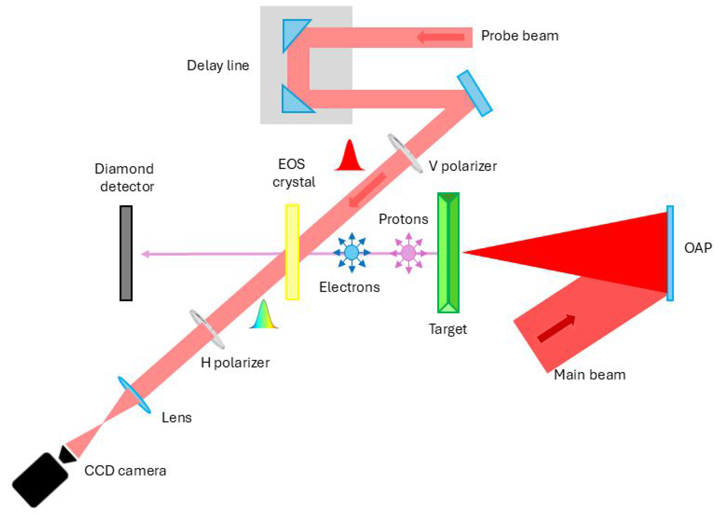
Figure 2.
EOS experimental setup: Side and top view (top) for the electron detection. The bunch travels normally and below the crystal surface, while the probe laser crosses the crystal with an incident angle. (Bottom) Working principle of the diagnostics: the electron Coulomb field induces a birefringence (blue region) in the crystal, which shifts downwards while the electric field penetrates in the crystal. The laser beam (pink region) crosses the sample and its polarization is rotated. Picture (top right) shows the signal (red region) created by the overlap; it’s flipped in both directions due to the imaging lens used in the setup.
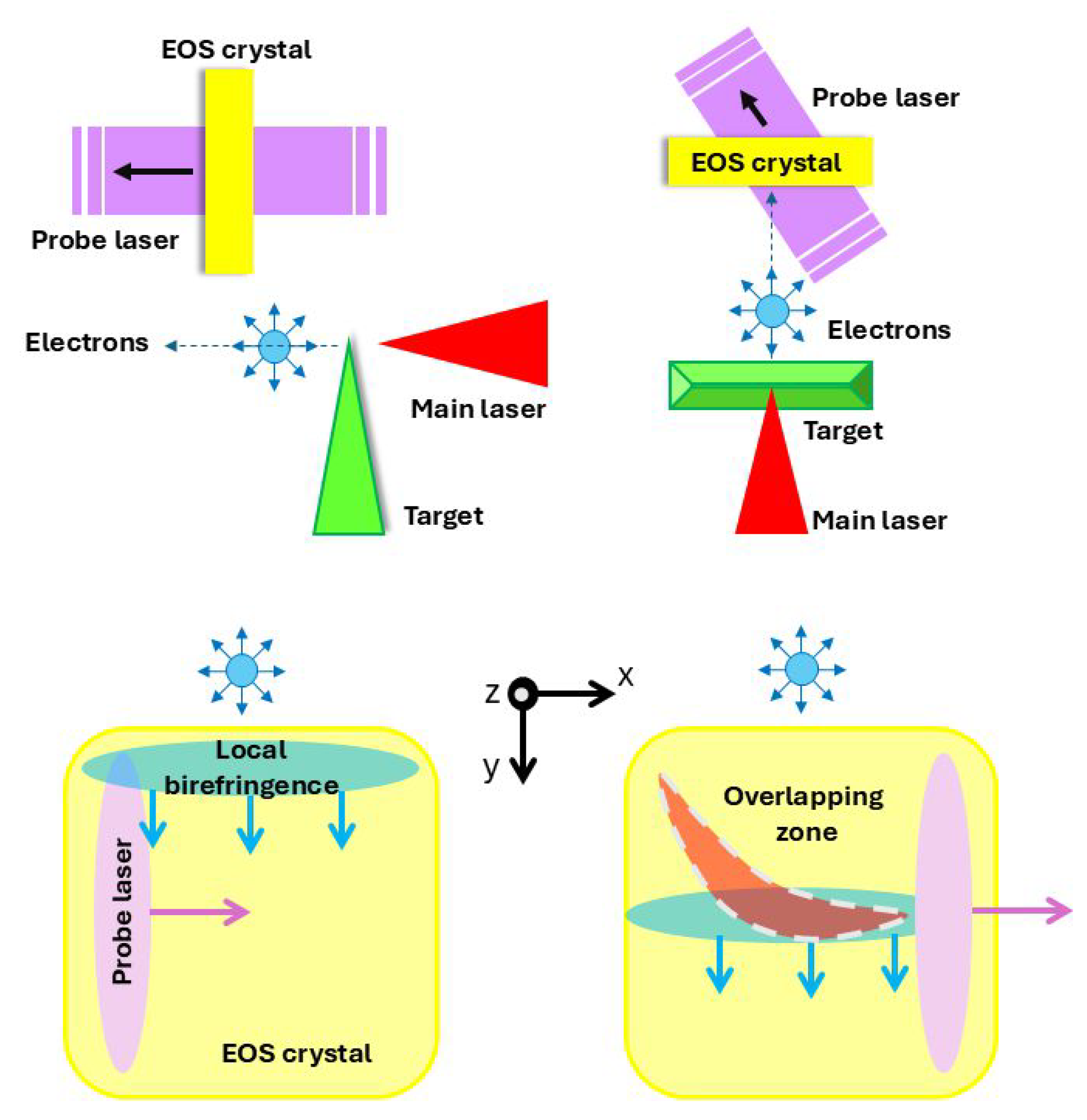
Figure 3.
Schematic layout of the TOF detector geometry. The layer structure in 3D view (left) and the surface Al interdigitated electrodes (right). Active area of the detector was , the metal fingers were processed to 20 m in width and the electrodes are spaced by 20 m.
Figure 3.
Schematic layout of the TOF detector geometry. The layer structure in 3D view (left) and the surface Al interdigitated electrodes (right). Active area of the detector was , the metal fingers were processed to 20 m in width and the electrodes are spaced by 20 m.
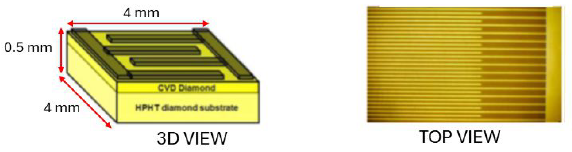
Figure 4.
EOS signal of fast electrons (left) and corresponding temporal profile of the electron bunch in the snapshot (right). A series of line-outs were performed along the time direction (white arrows), and the profile is obtained from the average of these line-outs. The error bars are the standard deviation of the average; the experimental results (blue points) are compared with a numerical simulation in MATLAB environment of the temporal profile (red dashed line).
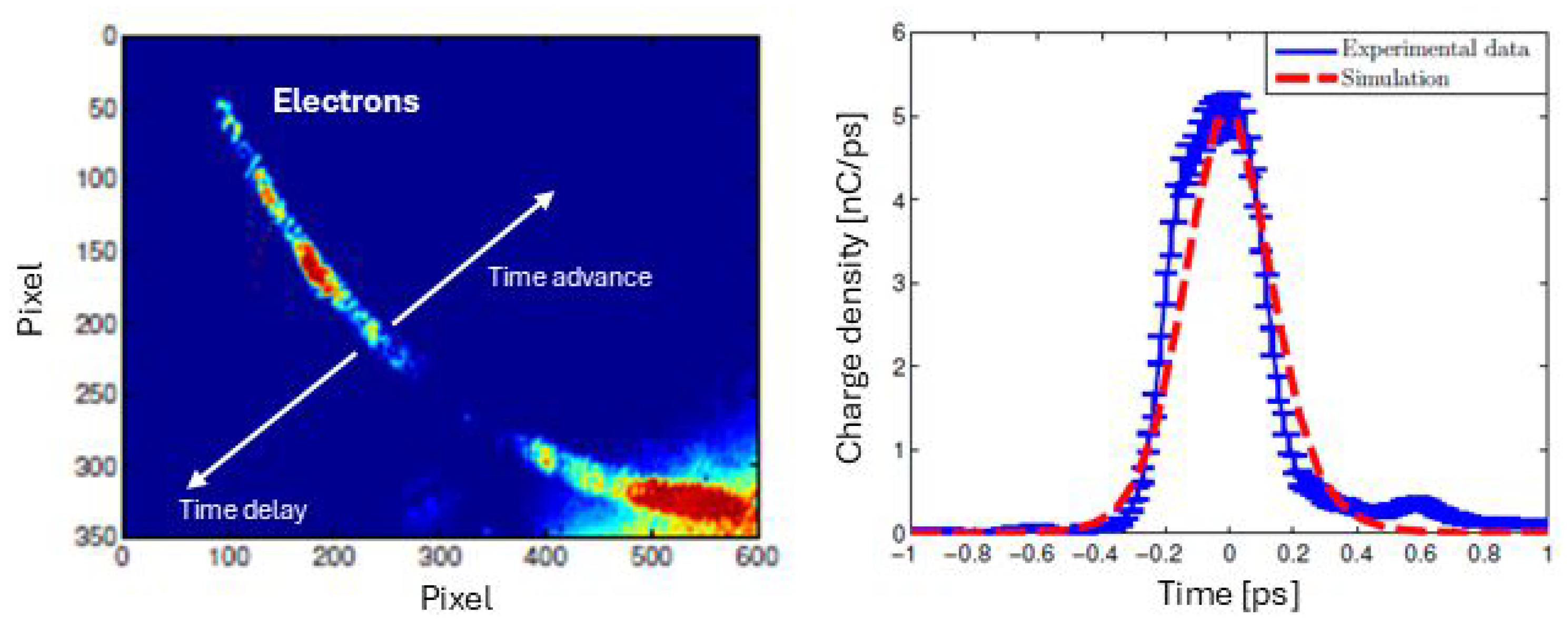
Figure 5.
Fast electrons bunches with different target geometries: (top-left) planar, (center) wedged and (top-right) tipped targets. The charges of the bunches are 1.2 nC (E1) and 3 nC (E2) for (top-left); 2 nC (E1) and 0.3 nC (E2) for (center), and 7 nC (E1) and 3 nC (E2) for (top-right). Longitudinal charge profiles of the snap-shots fitted by a gaussian function (red line) are shown in the bottom plots [18].

Figure 6.
Plots of the fast electrons charge (red points) and of the peak electric field (blue points) as function of the laser energy. (Top) Experimental data for the wedged-metallic target and (bottom) for the dielectric target [19].
Figure 6.
Plots of the fast electrons charge (red points) and of the peak electric field (blue points) as function of the laser energy. (Top) Experimental data for the wedged-metallic target and (bottom) for the dielectric target [19].
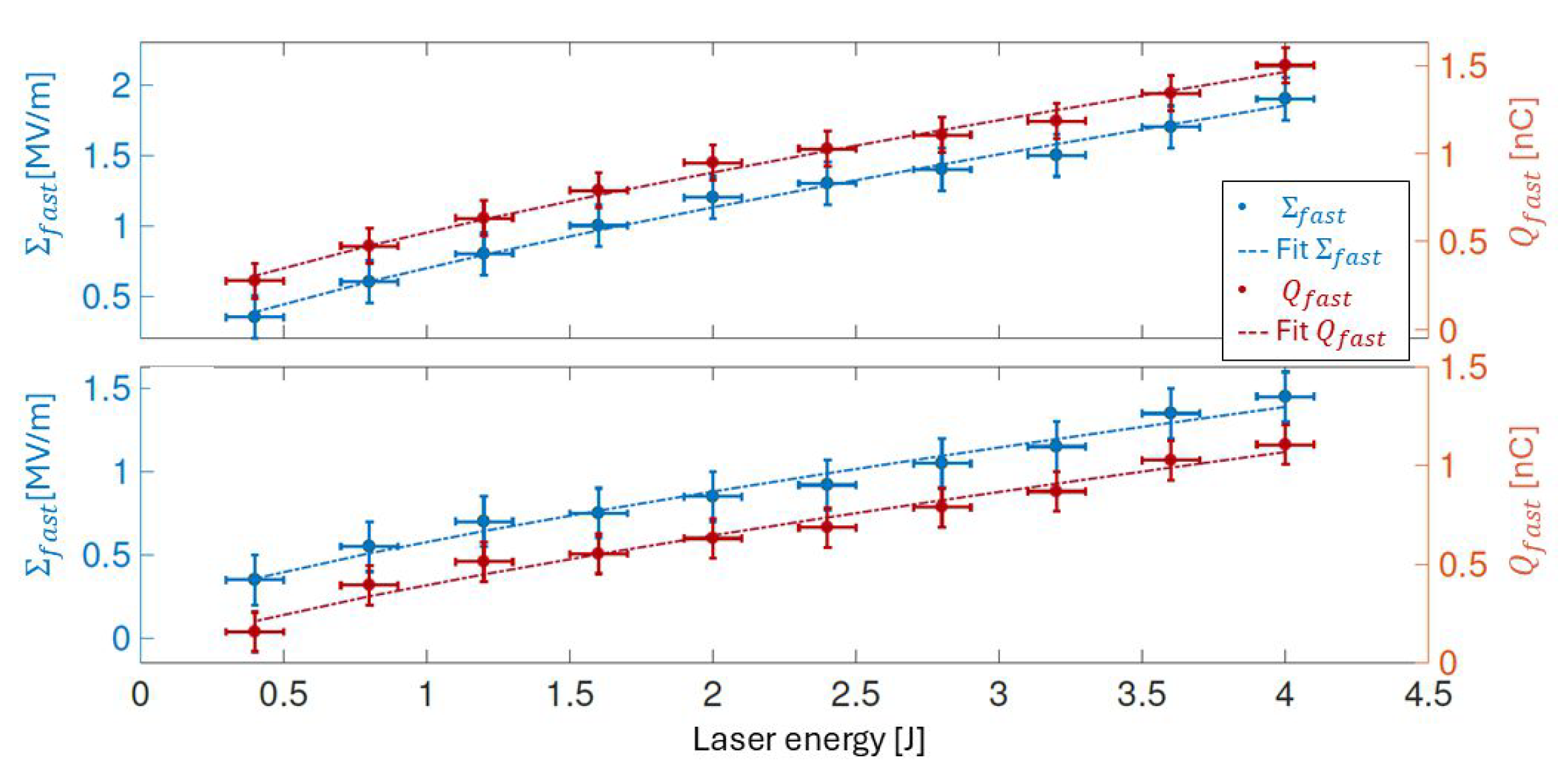
Figure 7.
Plots of the fast electrons temporal length as a function of the laser energy for the metallic target (circles and green dashed line) and for the dielectric target (diamonds and purple dashed line) [19].
Figure 7.
Plots of the fast electrons temporal length as a function of the laser energy for the metallic target (circles and green dashed line) and for the dielectric target (diamonds and purple dashed line) [19].
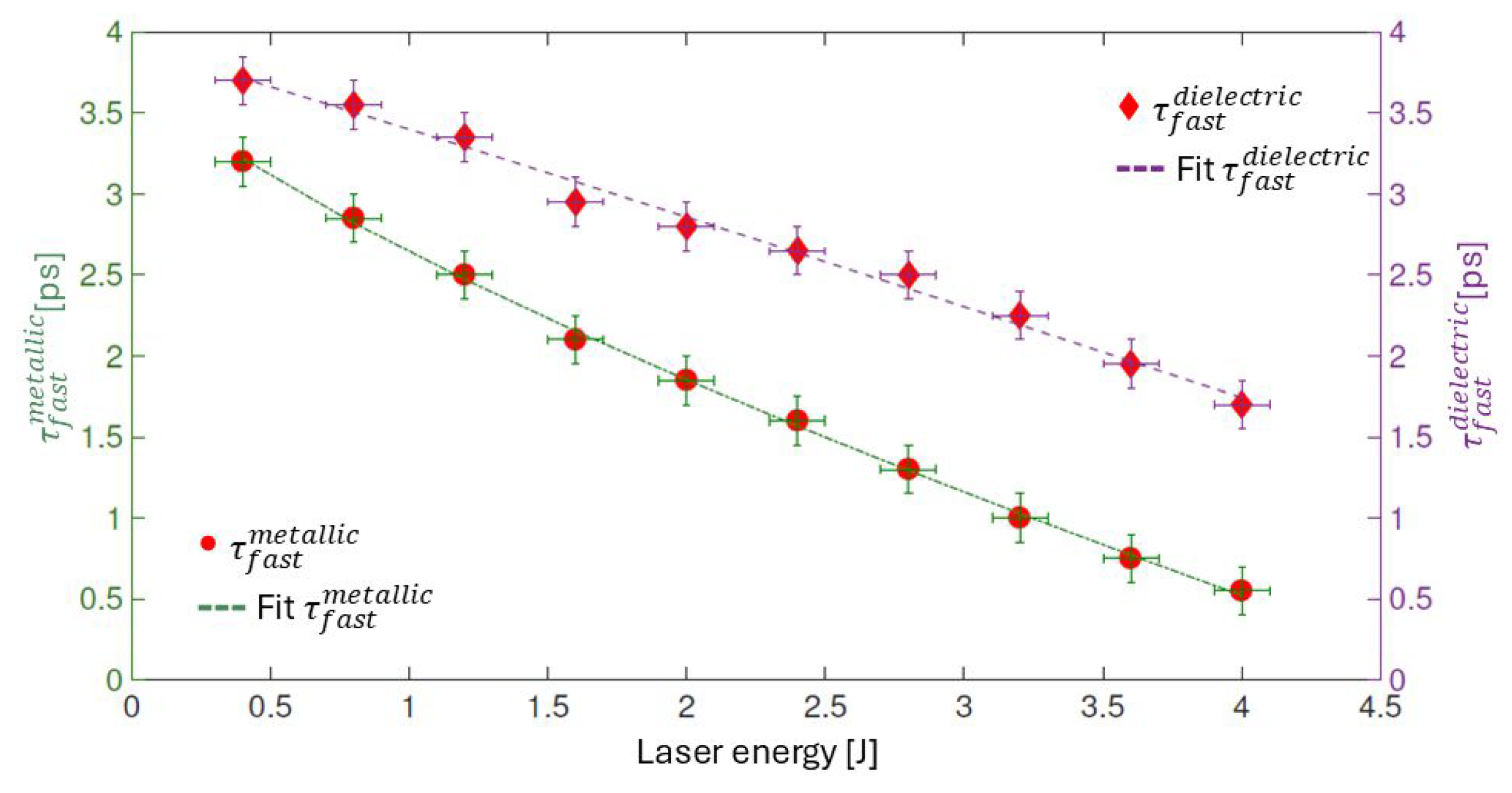
Figure 8.
Side view and top view of the EOS setup per EMPs detection. The black waves are the EMPs, they travel in free space to be detected by the diagnostics.
Figure 8.
Side view and top view of the EOS setup per EMPs detection. The black waves are the EMPs, they travel in free space to be detected by the diagnostics.
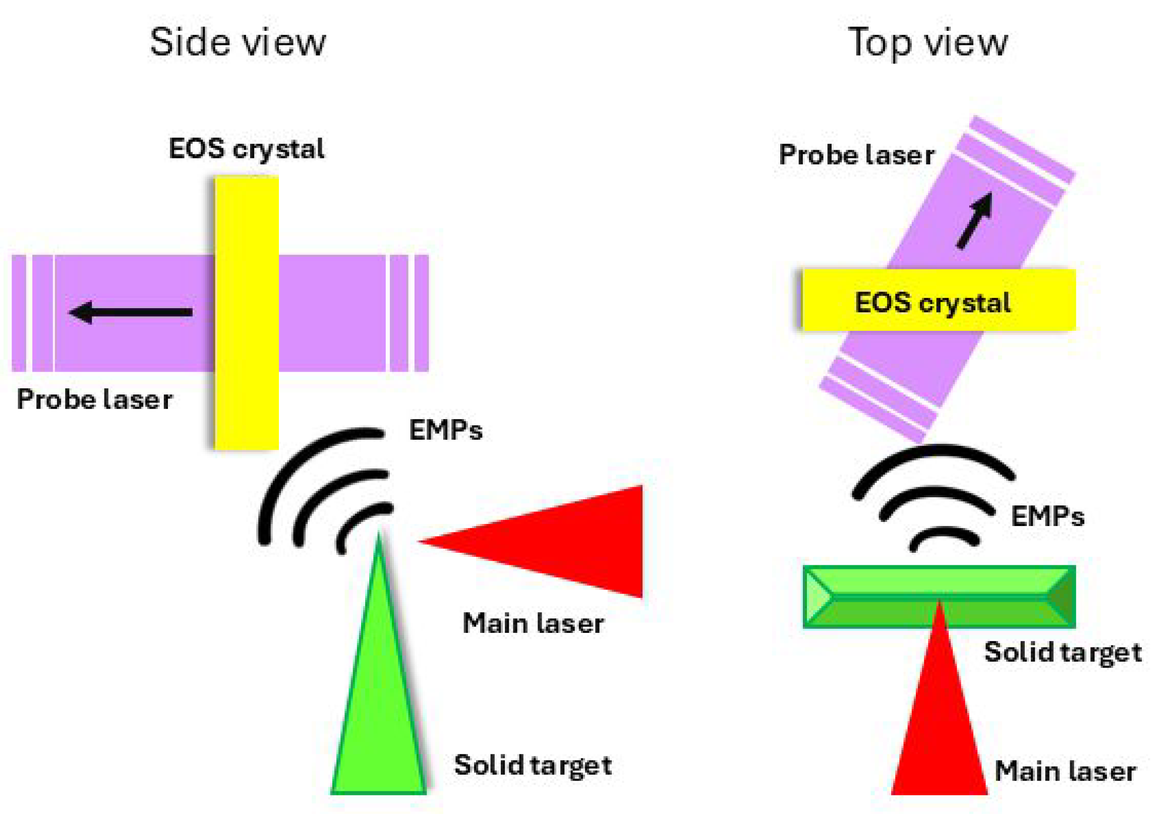
Figure 9.
EMPs signal on EOS diagnostics obtained at different delays of the probe beam [20].
Figure 9.
EMPs signal on EOS diagnostics obtained at different delays of the probe beam [20].

Figure 10.
The radiation pulse profile (left) is retrieved from the vertical thickness of the signal from EOS diagnostics at different laser energies. The duration is about 5 ps (at 10 %), 5.7 ps (at 50%) and 7.1 ps (at 100%). (right) The peak amplitudes of as function of the laser energy [20].
Figure 10.
The radiation pulse profile (left) is retrieved from the vertical thickness of the signal from EOS diagnostics at different laser energies. The duration is about 5 ps (at 10 %), 5.7 ps (at 50%) and 7.1 ps (at 100%). (right) The peak amplitudes of as function of the laser energy [20].

Figure 11.
(Left) Single-shot picture obtained with the EOS detector when the laser is focused on the 0.7 m-thick target at the full energy. Two electron bunches are detected simultaneously with the EMPs. (Right) Single-shot picture at 1 J laser energy, focused on the target bulk (6 m), with the probe laser delayed by 4ps. One slow electron bunch and EMPs are detected. [20].
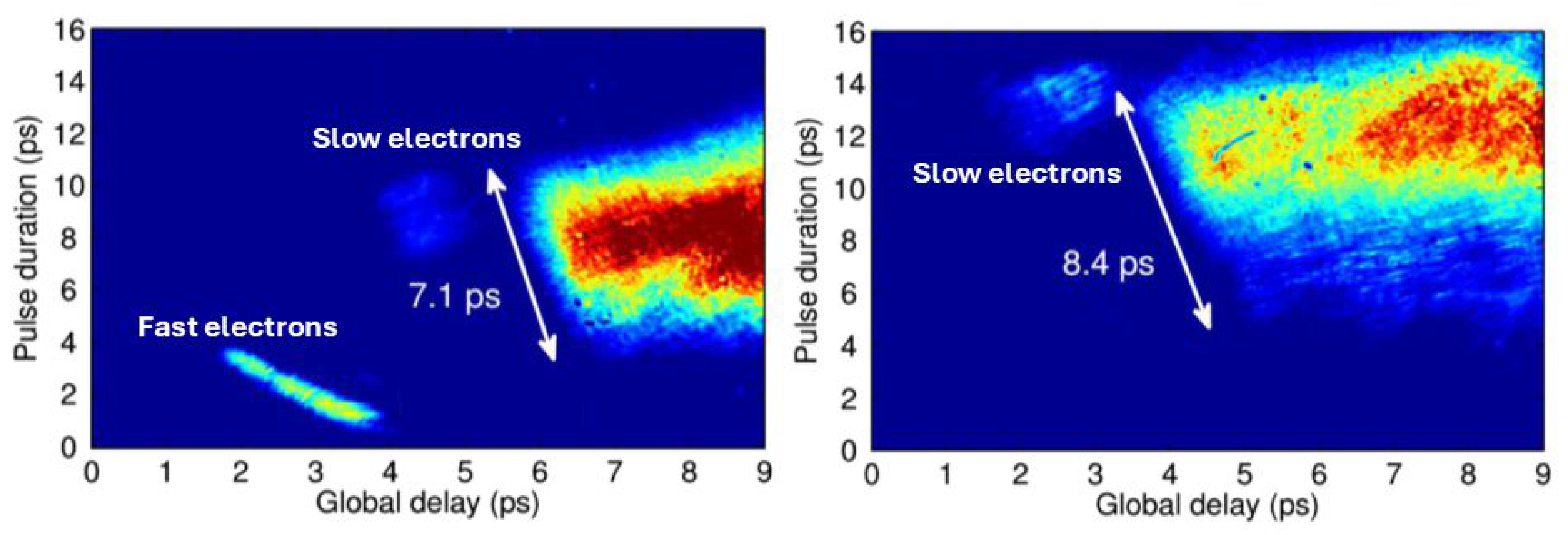
Figure 12.
Signal provided by the TOF detector and oscilloscope: the first peak on the left is associated with X-rays and electrons; the second peak is associated with proton bunches accelerated in the TNSA process. [21]
Figure 12.
Signal provided by the TOF detector and oscilloscope: the first peak on the left is associated with X-rays and electrons; the second peak is associated with proton bunches accelerated in the TNSA process. [21]
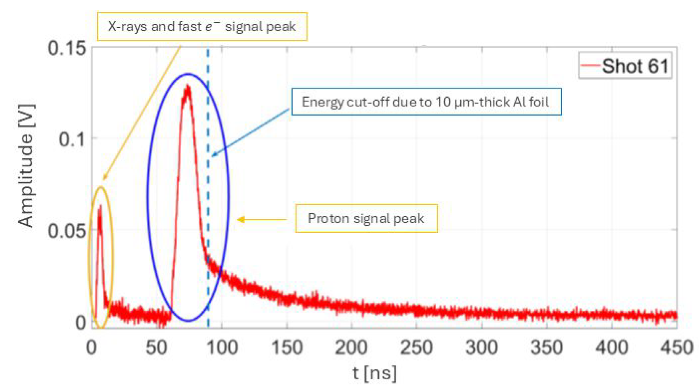
Figure 13.
Experimental data of the simultaneous detection of electron and proton beams. (Left) Plot of the electron beam charge, electron beam duration and proton maximum energy as function of the laser temporal length. (Right) Plot of the electron beam charge, electron beam duration and proton maximum energy as function of the laser spot size [23].
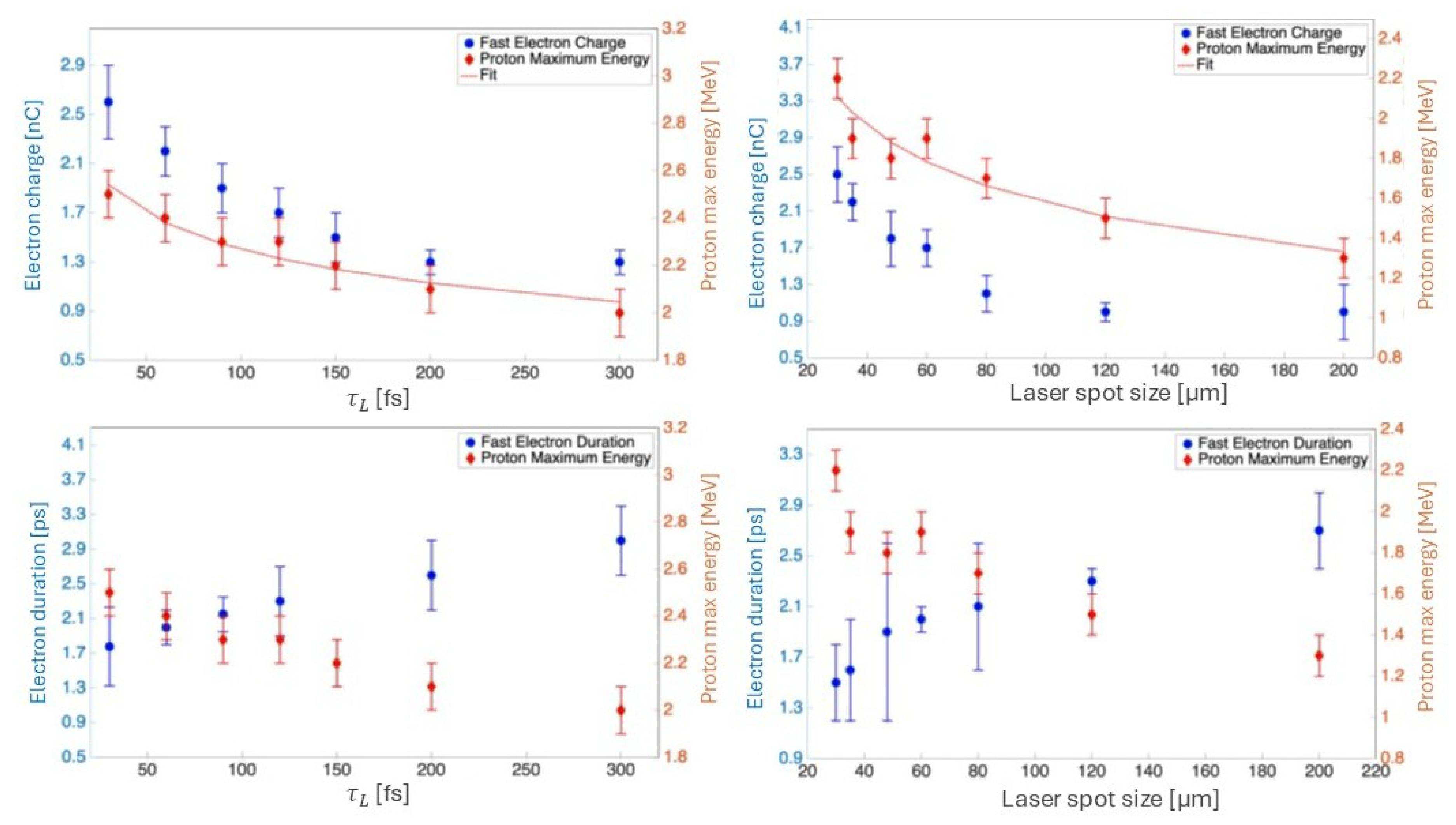
Figure 14.
Experimental data of the simultaneous detection of electron and proton beams. (Top) Plot of the electron beam charge(blue) and proton maximum energy(red) for different laser energies. For lower laser energy there is a reduction in both the emitted electron charge and the potential on the target, leading to a lower signal-to-noise ration and larger error bars.(Bottom) Plot of the electron beam duration (blue) and proton maximum energy (red) for different laser energies[34].
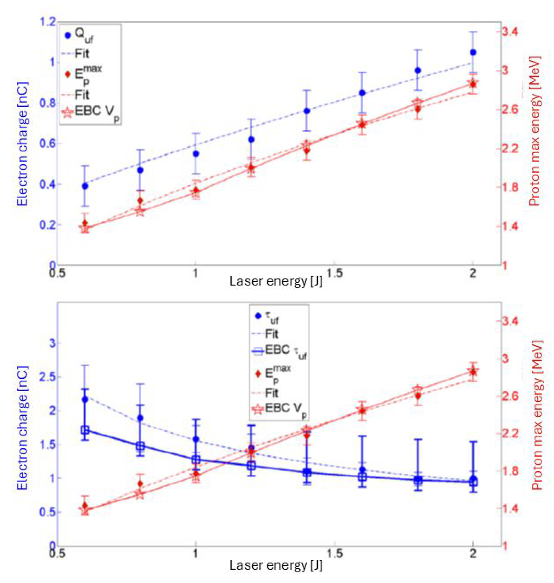
Figure 15.
Experimental data of proton maximum energy as a function of the electron beam duration (green) and charge (orange) [34].
Figure 15.
Experimental data of proton maximum energy as a function of the electron beam duration (green) and charge (orange) [34].
Disclaimer/Publisher’s Note: The statements, opinions and data contained in all publications are solely those of the individual author(s) and contributor(s) and not of MDPI and/or the editor(s). MDPI and/or the editor(s) disclaim responsibility for any injury to people or property resulting from any ideas, methods, instructions or products referred to in the content. |
© 2025 by the authors. Licensee MDPI, Basel, Switzerland. This article is an open access article distributed under the terms and conditions of the Creative Commons Attribution (CC BY) license (http://creativecommons.org/licenses/by/4.0/).
Copyright: This open access article is published under a Creative Commons CC BY 4.0 license, which permit the free download, distribution, and reuse, provided that the author and preprint are cited in any reuse.


