
Submitted:
02 May 2024
Posted:
07 May 2024
You are already at the latest version
Abstract
Laser-plasma interactions of ultra-short laser pulses with solid targets can generate highly intense pulses of protons and ions with energies of several MeV. The spectra of these particles are spread over a wide range following a Maxwellian distribution. We report on the design and testing of a magnetic chicane for the selection of protons within a limited energy window. It consists in two successive, anti-parallel dipole fields generated by cost-effective, permanent C-magnets with customized configuration and longitudinal positions. The chicane has been implemented into the target vessel of a petawatt laser facility under constraints on the direction of the incoming laser beam and guidance of the outgoing particles through a vacuum port. The separation of protons and carbon ions within distinct energy intervals has been demonstrated and compared to a ray tracing code.
Keywords:
laser-plasma acceleration
; proton
; mono-energetic beam
; magnetic dipole
1. Introduction
Ion acceleration by ultra-intense laser-plasma interactions has evolved as a core technique for compact sources of energetic particles [1,2]. In the so-called Target Normal Sheath Acceleration (TNSA) intense pulses of protons and light ions are released at laser intensities W/cm [3]. In this regime particle spectra cover a wide interval up to a sharp maximum energy, , typically of several MeV, with exponentially decreasing population. The generation of protons or light ions with comparatively narrow spectral distributions has been reported [4,5,6,7], albeit under experimental conditions in terms of laser pulse contrast or target properties which are not routinely met at present terawatt or petawatt laser facilities, especially when a stable operation over large numbers of shots is mandatory. Nevertheless, some applications of laser-accelerated particle beams do require narrow ion spectra, e.g., radiobiological studies with cell cultures [8], tissues [9], or higher organisms [10,11]. They usually rely on the selection of mono-energetic ions out of the initial, broad distribution by means of magnetic beam control elements. Resistive dipole and quadrupole fields can be tuned to the desired ion species, charge states, and energies [12,13]. However, their application is restricted to dedicated beamlines at large facilities. Compact arrangements of permanent magnets can be more flexibly implemented into a general-purpose laboratory for a short-term experimental campaign.
Combinations of permanent quadrupole magnets (PQMs) are suitable for the selective focusing of protons of a certain energy [14]. Such devices have been realized at various laser laboratories with two [15,16,17], four [18], or more [19] individual magnet blocks. Protons with narrow energy bands between 2 MeV and 14 MeV have been obtained, in some cases at high fluence corresponding to high, single-shot dose in radiobiology studies. For higher energies combinations of quadrupole and dipole magnets have been proposed [20,21]. The use of pulsed solenoids has been reported as well [9,22].
Permanent dipole magnets have been widely used for the selection of proton energies in laser-based radiobiology experiments. Three basic designs can be distinguished, the simplest one comprising a single field orientation perpendicular to the particle trajectories, Figure 1(a) [23,24,25,26]. A small portion of the initial beam along the target normal direction is selected by a collimator to reduce its angular spread. rays (moving along the initial beam axis) and electrons are efficiently separated from protons and the trajectories of the latter are split according to the energies. This allows for selection of a narrow energy interval by means of a second collimator behind the dipole field. It is also possible to select several distinct intervals at the same time [27]. Two anti-parallel magnetic fields can be used to control the direction of the outgoing ions and to reduce their angular spread in the space between the fields and the cell samples, Figure 1(b) [28,29]. With a combination of four field orientations and an intermediate collimator the mono-energetic beam can be re-directed to the initial axis, Figure 1(c) [30].
Here, the design of an energy selector based on two anti-parallel magnetic dipole fields is presented (Section 2) and its performance is demonstrated with laser-accelerated ions (Section 3). This chicane consists in cost-effective, permanent C-magnets which positions and orientations can be freely configured according to the actual, experimental geometry and the particle energy of interest.
2. Materials and Methods
The magnetic field of the energy selector is created by a set of identical, permanent C-magnets, Figure 2(a). Each C-magnet consists of two neodymium blocks (NdFeB N40, 60 (W) × 30 (L) × 15 (H) mm) attached to a steel yoke with outer dimensions 100 (W) × 30 (L) × 90 (H) mm. The yokes are nickelized for improved vacuum compatibility. With thin steel plates on top of each of the neodymium blocks the remaining gap height is reduced to 7 mm. The main component of the magnetic field strength, , on the central plane of a single magnet is shown in Figure 2(b). It was measured with a motorized Hall probe on a mesh of mm and interpolated for the graphical representation. The field strength is at the centre between the pole shoes.
The overall, field-filled space along the particle trajectories is generated by up to ten consecutive C-magnets in a support structure with outer dimensions 225 (W) × 446 (L) × 135 (H) mm. It consists of a stable frame made of aluminum profiles of 20 mm width. Each C-magnet is inserted into a pair of channel profiles screwed to the frame to fix the position in the longitudinal (z) direction. The lateral (x) placement of each C-magnet can be adjusted freely. Here too, the selected position is blocked by two sets of screws which can be moved along a groove. This arrangement allows for safe mounting of neighboring magnets with strong, repulsive forces. The magnet gap can be oriented towards either side of the profiles. The design and materials applied enable free configuration of the field geometry within the following limits:
- The field orientations can be parallel or antiparallel.
- The minimum, longitudinal distance of adjacent magnet yokes is 5 mm.
- A maximum of ten C-magnets can be installed.
- The gaps can reach a maximum, lateral distance of mm from the central axis.
Two examples for this flexible arrangement will be presented in Section 3 where several magnets with parallel field orientation form one or two main blocks. The entire set of C-magnets has a total weight of 18 kg. The outer frame is mounted on an aluminum breadboard and a lab jack for precise height adjustment.
The trajectories of particles within this energy selector have been simulated with a Python code based on the following assumptions. The particles (protons and ions) originate from a point-like source, the laser focal spot on a solid target foil. A collimator at distance from the target defines the maximum angles of acceptance for particles entering the selector, Figure 1(b). This collimator should be placed in target normal direction corresponding to the highest ion energies and flux in TNSA. A magnetic field acts on charged particles at longitudinal coordinates within the yokes. In addition, fringe fields up to mm from the borders of the yokes are taken into account. Some spaces are not affected by the fields, namely the interval between the collimator and the first magnet, , the distance between the two main blocks, , and the interval behind the last magnet, . With these calculations we obtained the particle spectral distributions inside a rectangular area at the distance of the detector or sample.
The simulation code allows for a horizontal rotation of the selector with respect to the target normal axis. The trajectories of carbon ions in different charge states from C to C have been simulated as well for comparison with experimental findings presented in Section 3.3. Furthermore, for beam tests at a cyclotron the energy loss of protons in air, obtained from SRIM [31], has been implemented into the Python code.
3. Results
To validate the simulated trajectories the guidance of a mono-energetic proton beam has been tested at an accelerator facility, Section 3.1. The dipole configuration has been adapted to the experimental setup inside the target vessel of the VEGA-3 laser at the Spanish Pulsed Laser Center (CLPU, Salamanca), Section 3.2. First experimental data from laser-plasma interactions, Section 3.3, show the spectral separation of protons and carbon ions at this laboratory.
3.1. Test at CNA Cyclotron in Air
The guidance of particles through the selector was tested with a monoenergetic proton beam from a radiofrequency accelerator. Two anti-parallel magnetic fields were generated with five dipoles in the first block, and four, in the second, as shown in Figure 3. Measurements were performed at the external beamline of the 18 MeV cyclotron of Centro Nacional de Aceleradores, Seville [32]. After passage through an aluminum attenuator of 500 µm thickness and a vacuum window consisting of a 100 µm thin aluminum foil the proton beam energy in air was of 14.49 MeV. The selector was placed 15.5 cm behind the beam outlet, Figure 3(a). Two consecutive, circular collimators of 3 mm and 1 mm aperture, the smaller one closely in front of the first dipole magnet, were used to delimit the beam diameter at the entrance of the selector. The beam entrance position and the horizontal orientation were adjusted with alignment lasers.
Radiochromic film (RCF) samples were placed between consecutive C-magnets to trace the beam position through the entire device. Only one sample was irradiated at the same time. The spots visible on the inset of Figure 4(a) were obtained with beam currents of 4-10 nA and irradiation times of 1-4 minutes. The lateral displacements of the proton beam at six longitudinal positions coincide within mm with simulations accounting for the energy loss in air and a 1.5° rotation angle of the selector in the horizontal plane with respect to the beam axis. These results confirm the validity of the applied ray tracing code with a simulated field configuration made of identical, consecutive dipole fields.
3.2. Specific Configuration for VEGA-3
The 1 PW laser facility VEGA-3 provides up to 30 J beam energy in pulses with a minimum duration of 30 fs. The laser is focalized by a off-axis parabola located inside a dedicated vacuum chamber. The focal point lies at a fixed position inside a second, rectangular vessel with inner dimensions mm in the horizontal plane. The laser entrance is along the central axis of the interaction chamber, Figure 5.
Several side conditions had to be fulfilled for the present experiment with the aim of generating laser-accelerated proton beams and demonstrating the spatial separation of particles after passage through the energy selector. First, the target foil must be rotated by 10°-20° with respect to the incoming laser beam to avoid back reflection and potential damage of the optical systems. This implies a rotation of the target normal direction and, by consequence, of the selector with respect to the central axis of the vacuum chamber. The second condition was imposed by the optical system necessary to adjust the target precisely at the focal spot position. These components were mounted on motorized stages and placed between the target wheel and the selector before each series of shots. The front side of the selector was 332 mm away from the focal spot to allow for this operation. Third, the outgoing, monoenergetic proton beam should leave the chamber through one of the ports on the rear wall, inside the horizontal plane and pointing towards the focal spot. This port is equipped with a vacuum window of 50 mm width and 5 mm height sealed with a 12.7 µm thin kapton foil to allow for particle passage to the atmosphere. In the simulations it is implemented to study the angular dependence of the particle energies and fluence behind the selector.
For several magnet combinations the trajectories of protons within the envisaged range of energies (4-8 MeV) were simulated and combined with a 3D CAD model of the entire setup. At this stage only protons emitted on the target normal axis were considered. An asymmetric configuration introduces a non-zero angle between the outgoing particles and the initial, target normal direction. This feature was exploited to guide the protons through the ports. A large lateral deviation would be obtained with a single block of five parallel C-magnets, Figure 6. However, the divergence of protons with different energies leads to a low fluence on the detector plane. Instead, a 5+4 combination as shown in Figure 5 and Figure 3(b) was chosen to guide the protons towards the port at 12.2° with respect to the chamber axis.
With the 5+4 configuration, Figure 7 shows simulated proton spectra at three horizontal positions, , on the vacuum window with mm corresponding to the limit being closest to the initial beam axis where the highest proton energies are expected. For these calculations the angular acceptance of a slit collimator of 5 mm width in front of the first C-magnet was used, in agreement with the measurements presented in Section 3.3. The simulated energies initially are uniformly distributed within MeV; protons with MeV are deflected far from the window. The typical, exponential distribution of ions generated in TNSA was emulated applying a factor to each energy bin, with MeV close to measured results from VEGA-3. The three energy intervals of Figure 7 range from 2.9-4.1 MeV ( mm), 3.6-5.5 MeV ( mm), and 5.0-8.6 MeV ( mm), respectively. Particles at low energies show the smallest spectral width within a predefined detection interval due to their comparatively strong deflection.
3.3. Experiment at VEGA-3
The energy selector has been implemented into the VEGA-3 target chamber to demonstrate the generation of mono-energetic bunches of laser-accelerated protons, Figure 5. Aluminum membranes of 7 µm thickness were placed at the focal spot position by use of a motorized target wheel assembly [33] allowing for 808 individual shots in a single vacuum cycle. The target was rotated 17° with respect to the incoming laser direction. Protons were generated in the interaction of 200 fs laser pulses of 6-27 J (before compression). In a first series of measurements the particles were detected on a plastic scintillator placed at the end of a vacuum pipe mounted on the 12.2° port. It allows for obtaining the proton energies by the time-of-flight (TOF) method. The flux is reconstructed from the signal height on a 3 GHz oscilloscope [34]. A slit collimator of 7.5 mm width was mounted in front of the scintillator to detect only particles within a small horizontal interval. These measurements were carried out two times to detect the full spectrum emitted from the target (without the selector) or the protons passing through the chicane (with the selector at the predefined position). Without the selector, allowing for direct view from the TOF detector to the target, a sharp peak close to ns is observed, Figure 8(a), caused by high-energy photons from the laser-plasma interaction. Visible light from the laser-plasma interaction was detected on a photodiode which was connected to a different oscilloscope channel and, by previous calibration with the peak, provided a reference time for all subsequent measurements. The peak is followed by a broad pulse from protons with time-of-flight in the range 100-500 ns. High-frequency fluctuations of the signal height, especially within the first 100 ns of the signal, which are caused by an electromagnetic pulse (EMP) generated in the laser-plasma interaction [35], were partly filtered out by a Fast Fourier transform. The corresponding, spectral distribution with a maximum energy of 5 MeV is shown in Figure 8(b).
In a second step the energy selector was inserted with a pinhole collimator of 2 mm diameter in front of the first dipole. A 1.5 mm thick lead shielding covered the front side of the selector to absorb radiation at larger angles including the straight connecting line between the target and the TOF detector. By consequence, the peak is not visible here. Instead, only one sharp peak is observed (same Figures, in red). Its timing with respect to the laser-plasma interaction was determined with the previously calibrated photodiode. The reconstructed proton energies indicate a quasi-mono-energetic peak at about 4.8 MeV. These data were obtained with 12 J laser pulses; mono-energetic peaks at the same position were observed with 17 J and 20 J as well.
Additional data were taken after removing the TOF detector setup and mounting a vacuum window on the same port of the interaction chamber. Here, a slit collimator of 5 mm width was positioned at the selector entrance. The distribution of proton energies right outside the window has been measured with radiochromic films (RCF) of type Gafchromic EBT3-U, a material with a 28 µm thick sensitive layer on top of a 125 µm substrate. A stack of four RCF has been placed directly behind the kapton window, with 44 µm aluminum foils on top of each EBT3-U film, to obtain a depth-dose profile from 20 accumulated laser shots. Figure 9(a) shows these four layers with the right end oriented towards the biggest magnetic deflection, mm. The corresponding dose values, obtained from the previously calibrated relation between optical density (OD) and radiation dose and normalized to one single shot, are shown for each layer as solid curves in Figure 9(b). In layers 2-4 a maximum OD is visible which position moves towards the high-energy (left) end at increasing depths. We have calculated the energy loss in the kapton window, aluminum foils, and the radiochromic films with SRIM [31] to obtain the minimum energies of protons necessary to reach the active layers of RCF 2 (5.0 MeV), RCF 3 (6.9 MeV), and RCF 4 (8.4 MeV), respectively. The corresponding limits of hit positions, obtained with our ray tracing code, are indicated by the arrows. Their coordinates at 1221 mm target distance coincide within mm with the peaks in the dose profiles confirming qualitatively the expected, spatial separation of protons with different energies.
The measured dose values have been used to retrieve the spectral components of the proton beam making use of the known relation between the linear energy transfer in water, , the proton fluence, , and the dose deposition, D,
In layer 4 all the protons are assigned a common energy beyond the previously indicated limit of 8.4 MeV. The number of particles per cm required to produce the observed dose is calculated using eq. (1). For layer 3 the calculation is repeated within the corresponding energy interval but accounting for the dose deposited by the transient protons, and accordingly for layers 2 and 1. Figure 10 shows two examples: at mm, indicated by an arrow in Figure 9, the upper limit of proton energies is of 8.4 MeV as no dose is measured in layer 4. The proton fluence at MeV corresponds to layer 3. Here, the distribution peaks at MeV (layer 2); additional protons with MeV are not required to reproduce the measured value of layer 1. Further towards the low-energy end of the window, at mm, the leading contribution stems from energies within MeV.
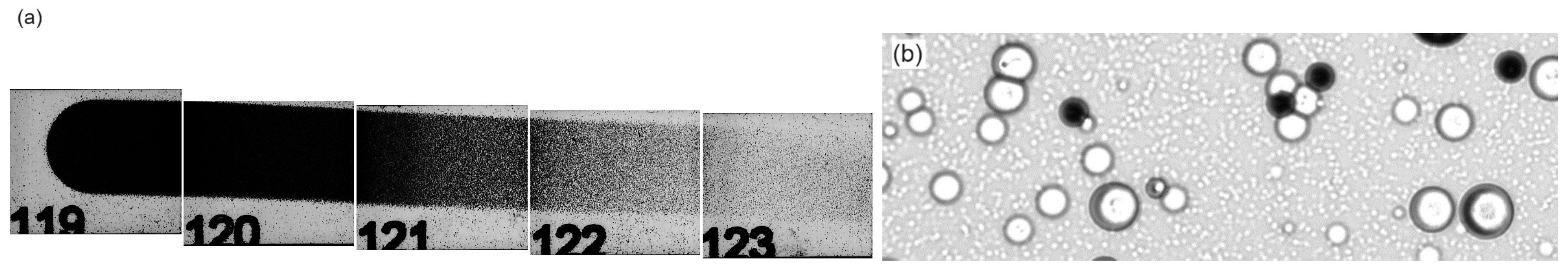
In order to investigate the presence of ions heavier than hydrogen five PADC plates of 1 cm size (Tastrak, TASL, UK) were placed closely behind the kapton window. They were exposed to particles from a single shot with 27 J laser energy. After etching (2 hours at 90 °C in 6.25M NaOH) a variation of the track density, visualized by transmission scan, along the horizontal direction is observed, Figure 11(a). The region of highest optical density is close to the target normal direction. For protons generated in TNSA with exponentially decaying spectra the opposite tendency would be expected as those of lower energies undergo stronger deflection inside the selector. Under a track microscope (Radosys PT10) two classes of patterns with very different diameters can be perceived, Figure 11(b). The density of the larger ones decreases from the left to the right end of Figure 11(a); individual pits can only be distinguished on the two rightmost plates. Due to their size, and taking into account the etching conditions, these tracks can be attributed to carbon ions [36]. Indeed, the simultaneous acceleration of protons and light ions is characteristic of the TNSA process. According to the SRIM simulation code [31] carbon ions of more than 12 MeV penetrate through the 12.7 µm kapton foil and potentially reach the PADC plates.
We have simulated the trajectories of carbon ions in different charge states (C to C) and with energies of 12-84 MeV. Taking into account the beam divergence due to the finite angular acceptance of the collimator these calculations indicate that C ions are spread over the entire width of the vacuum window, albeit with higher abundance at coordinates corresponding to the plates with serial numbers 119-121 of Figure 11(a). C ions can only be found on the left half of the vacuum window, and C ions only on plate 119. The lateral deflection of carbon ions with charge states lower than 4+ is insufficient to reach the kapton window. These simulations confirm the classification of the large pits and provide a plausible explanation for the gradient in large track densities from the left to the right end of the beam window. Note that the carbon ions do not contribute to the dose distributions in the RCF of Figure 9 as they are stopped in the aluminum layer in front.
On the PADC plates 122 and 123 the tiny tracks of Figure 11(b) have been counted within selected regions. For these, track densities are highest close to the right end of the vacuum window (/cm) and decrease to 2.5-/cm at about 20 mm from the right end. This gradient is expected for protons with an exponential energy distribution typical for TNSA as those of lower energies undergo stronger deflection. From eq. (1) the highest single-shot dose as determined with PADC amounts to 0.135 Gy.
4. Conclusions
A magnetic dipole chicane for the spectral separation of laser-accelerated protons has been tested at the VEGA-3 facility. Its highly flexible design relies on a series of identical C-magnets mounted inside a stable frame allowing for customized implementation into an experimental setup. Beam transport towards a vacuum window has been achieved by choice of the longitudinal dimensions of the two anti-parallel field regions. The guidance of a mono-energetic proton beam through the field has been tested in air by comparing the measured, horizontal displacement of the beam center with the simulated trajectories. The energetic separation of protons from highly intense laser-plasma interactions has been demonstrated. Carbon ions released in the same reactions have been detected as well in agreement with simulations.
The present study focuses on the energy range between 4 MeV and 8 MeV. Protons of lower energies can be guided with fewer dipoles. For an effective separation of higher energies it may be advantageous to increase the number of C-magnets with only one field orientation; a maximum of 10 dipoles fit inside the existing frame. Similar, permanent C-magnets with higher field strength could be realized by reducing the gap size between the neodymium blocks.
The energy selector has been designed for in-vitro radiobiology experiments with laser-accelerated protons and ions. The irradiation of biological samples must be carried out with particles of limited spectral width to guarantee a comparable dose deposition in all the cells. This can be achieved by choosing a small horizontal interval along the vacuum exit window. In practice, a compromise between the spectral width (dose uniformity) and particle fluence (single-shot dose) must be drawn. As an example, the spatial separation between protons of different energies is higher in the 5+0 configuration of Figure 6 but the fluence on the target plane is much lower than with the 5+4 combination, Figure 5.
The large spectral width of ions released in laser-plasma interactions is one of the distinctive features as compared to radiofrequency accelerators. Mono-energetic particle beams are advantageous for many applications. For instance, protons above a specific energy threshold can induce nuclear reactions on a secondary target. Those at lower energies and with large populations in the initial spectra can be filtered out with magnetic fields to avoid unnecessary heat deposition and background generation. Our dipole chicane may be adapted to the experimental requirements, especially at laser facilities which do not provide a permanent, dedicated beamline with magneto-optical elements.
Author Contributions
Conceptualization, M.S.; methodology, A.R., D.E. and M.S.; software, A.R., D.E. and J.J.-M.; validation, A.A., J.B., J.I.A. and M.E.; formal analysis, A.R. and M.S.; investigation, A.R., D.E., A.A., J.I.A., A.B., J.B., M.E., J.G.L., C.M., D.P., M.R.R. and M.S.; resources, M.C.J.-R.; data curation, A.R. and M.S.; writing—original draft preparation, M.S.; writing—review and editing, A.A. and J.B.; visualization, J.J.-M. and M.S.; supervision, A.A., J.B., M.E. and M.S.; project administration, J.B. and M.S.; funding acquisition, J.B., M.D.R.-F. and M.S. All authors have read and agreed to the published version of the manuscript.
Funding
Project CIAICO/2022/008 funded by the regional government (Generalitat Valenciana) in the program “I+D+i Subvenciones para grupos de investigación consolidados AICO”. Additional support by Generalitat Valenciana in the Garantía Juvenil program, ref. EDGJID/2021/204. The authors would like to thank the Spanish Center of Pulsed Lasers (CLPU) and the members of the Consortium (Central Government, Regional Government of Castilla y León and Universidad de Salamanca) for considering experiment 00562-0101 as a strategic proposal that develops new potentialities for CLPU and, therefore, finance the access to its facilities, as well as to acknowledge the results obtained with its petawatt laser system (VEGA-3) and its scientific and technical assistance. Supported by the Government of Castilla y León under the project CLP263P20 “Transport and manipulation of particles in laser accelerators: New scenarios in flash radiotherapy (TYMPAL), co-financed with FEDER funds. M.C. Jiménez-Ramos acknowledges the support to this work through a VI PPIT-US contract.
Data Availability Statement
Data supporting the conclusions is presented in the article. Additional data available on request from the authors.
Acknowledgments
M.S. greatly acknowledges logistic support provided by Mavi Campos Lleó and Elisa Arias for the realization of the experimental studies.
Conflicts of Interest
The authors declare no conflict of interest. The funders had no role in the design of the study; in the collection, analyses, or interpretation of data; in the writing of the manuscript; or in the decision to publish the results.
References
- Daido, H.; Nishiuchi, M.; Pirozhkov, A.S. Review of laser-driven ion sources and their applications. Reports on Progress in Physics 2012, 75, 056401. [Google Scholar] [CrossRef] [PubMed]
- Macchi, A.; Borghesi, M.; Passoni, M. Ion acceleration by superintense laser-plasma interaction. Rev. Mod. Phys. 2013, 85, 751–793. [Google Scholar] [CrossRef]
- Roth, M.; Schollmeier, M. Ion Acceleration-Target Normal Sheath Acceleration. CERN Yellow Reports 2016, 1, 231. [Google Scholar]
- Schwoerer, H.; Pfotenhauer, S.; Jäckel, O.; Amthor, K.U.; Liesfeld, B.; Ziegler, W.; Sauerbrey, R.; Ledingham, K.; Esirkepov, T. Laser-plasma acceleration of quasi-monoenergetic protons from microstructured targets. Nature 2006, 439, 445. [Google Scholar] [CrossRef] [PubMed]
- Henig, A.; Steinke, S.; Schnürer, M.; Sokollik, T.; Hörlein, R.; Kiefer, D.; Jung, D.; Schreiber, J.; Hegelich, B.M.; Yan, X.Q.; et al. Radiation-Pressure Acceleration of Ion Beams Driven by Circularly Polarized Laser Pulses. Phys. Rev. Lett. 2009, 103, 245003. [Google Scholar] [CrossRef] [PubMed]
- Haberberger, D.; Tochitsky, S.; Fiuza, F.; Gong, C.; Fonseca, R.A.; Silva, L.O.; Mori, W.B.; Joshi, C. Collisionless shocks in laser-produced plasma generate monoenergetic high-energy proton beams. Nature Physics 2012, 8, 95. [Google Scholar] [CrossRef]
- Palaniyappan, S.; Huang, C.; Gautier, D.C.; Hamilton, C.E.; Santiago, M.A.; Kreuzer, C.; Sefkow, A.B.; Shah, R.C.; Fernández, J.C. Efficient quasi-monoenergetic ion beams from laser-driven relativistic plasmas. Nature Communications 2015, 6, 10170. [Google Scholar] [CrossRef] [PubMed]
- Chaudhary, P.; Milluzzo, G.; Ahmed, H.; Odlozilik, B.; McMurray, A.; Prise, K.M.; Borghesi, M. Radiobiology Experiments With Ultra-high Dose Rate Laser-Driven Protons: Methodology and State-of-the-Art. Frontiers in Physics 2021, 9, 75. [Google Scholar] [CrossRef]
- Brack, F.E.; Kroll, F.; Gaus, L.; Bernert, C.; Beyreuther, E.; Cowan, T.E.; Karsch, L.; Kraft, S.; Kunz-Schughart, L.A.; Lessmann, E.; et al. Spectral and spatial shaping of laser-driven proton beams using a pulsed high-field magnet beamline. Scientific Reports 2020, 10, 9118. [Google Scholar] [CrossRef]
- Rösch, T.F.; Szabó, Z.; Haffa, D.; Bin, J.; Brunner, S.; Englbrecht, F.S.; Friedl, A.A.; Gao, Y.; Hartmann, J.; Hilz, P.; et al. A feasibility study of zebrafish embryo irradiation with laser-accelerated protons. Review of Scientific Instruments 2020, 91, 063303. [Google Scholar] [CrossRef]
- Kroll, F.; Brack, F.E.; Bernert, C.; Bock, S.; Bodenstein, E.; Brüchner, K.; Cowan, T.E.; Gaus, L.; Gebhardt, R.; Helbig, U.; et al. Tumour irradiation in mice with a laser-accelerated proton beam. Nature Physics 2022, 18, 316–322. [Google Scholar] [CrossRef]
- Aymar, G.; Becker, T.; Boogert, S.; Borghesi, M.; Bingham, R.; Brenner, C.; Burrows, P.N.; Ettlinger, O.C.; Dascalu, T.; Gibson, S.; et al. LhARA: The Laser-hybrid Accelerator for Radiobiological Applications. Frontiers in Physics 2020, 8, 567738. [Google Scholar] [CrossRef]
- Cirrone, G.A.P.; Petringa, G.; Catalano, R.; Schillaci, F.; Allegra, L.; Amato, A.; Avolio, R.; Costa, M.; Cuttone, G.; Fajstavr, A.; et al. ELIMED-ELIMAIA: The First Open User Irradiation Beamline for Laser-Plasma-Accelerated Ion Beams. Frontiers in Physics 2020, 8, 564907. [Google Scholar] [CrossRef]
- Lim, J.K.; Frigola, P.; Travish, G.; Rosenzweig, J.B.; Anderson, S.G.; Brown, W.J.; Jacob, J.S.; Robbins, C.L.; Tremaine, A.M. Adjustable, short focal length permanent-magnet quadrupole based electron beam final focus system. Phys. Rev. ST Accel. Beams 2005, 8, 072401. [Google Scholar] [CrossRef]
- Schollmeier, M.; Becker, S.; Geißel, M.; Flippo, K.A.; Blažević, A.; Gaillard, S.A.; Gautier, D.C.; Grüner, F.; Harres, K.; Kimmel, M.; et al. Controlled Transport and Focusing of Laser-Accelerated Protons with Miniature Magnetic Devices. Phys. Rev. Lett. 2008, 101, 055004. [Google Scholar] [CrossRef] [PubMed]
- Nishiuchi, M.; Daito, I.; Ikegami, M.; Daido, H.; Mori, M.; Orimo, S.; Ogura, K.; Sagisaka, A.; Yogo, A.; Pirozhkov, A.S.; et al. Focusing and spectral enhancement of a repetition-rated, laser-driven, divergent multi-MeV proton beam using permanent quadrupole magnets. Applied Physics Letters 2009, 94, 061107. [Google Scholar] [CrossRef]
- Bin, J.; Allinger, K.; Assmann, W.; Dollinger, G.; Drexler, G.A.; Friedl, A.A.; Habs, D.; Hilz, P.; Hoerlein, R.; Humble, N.; et al. A laser-driven nanosecond proton source for radiobiological studies. Applied Physics Letters 2012, 101, 243701. [Google Scholar] [CrossRef]
- Pommarel, L.; Vauzour, B.; Mégnin-Chanet, F.; Bayart, E.; Delmas, O.; Goudjil, F.; Nauraye, C.; Letellier, V.; Pouzoulet, F.; Schillaci, F.; et al. Spectral and spatial shaping of a laser-produced ion beam for radiation-biology experiments. Phys. Rev. Accel. Beams 2017, 20, 032801. [Google Scholar] [CrossRef]
- Brandi, F.; Labate, L.; Palla, D.; Kumar, S.; Fulgentini, L.; Koester, P.; Baffigi, F.; Chiari, M.; Panetta, D.; Gizzi, L.A. A Few MeV Laser-Plasma Accelerated Proton Beam in Air Collimated Using Compact Permanent Quadrupole Magnets. Applied Sciences 2021, 11. [Google Scholar] [CrossRef]
- Romano, F.; Schillaci, F.; Cirrone, G.; Cuttone, G.; Scuderi, V.; Allegra, L.; Amato, A.; Amico, A.; Candiano, G.; De Luca, G.; et al. The ELIMED transport and dosimetry beamline for laser-driven ion beams. Nuclear Instruments and Methods in Physics Research Section A: Accelerators, Spectrometers, Detectors and Associated Equipment 2016, 829, 153–158. [Google Scholar] [CrossRef]
- Scisciò, M.; Migliorati, M.; Palumbo, L.; Antici, P. Design and optimization of a compact laser-driven proton beamline. Scientific Reports 2018, 8, 6299. [Google Scholar] [CrossRef] [PubMed]
- Busold, S.; Schumacher, D.; Deppert, O.; Brabetz, C.; Frydrych, S.; Kroll, F.; Joost, M.; Al-Omari, H.; Blažević, A.; Zielbauer, B.; et al. Focusing and transport of high-intensity multi-MeV proton bunches from a compact laser-driven source. Phys. Rev. ST Accel. Beams 2013, 16, 101302. [Google Scholar] [CrossRef]
- Metzkes, J.; Cowan, T.; Karsch, L.; Kraft, S.; Pawelke, J.; Richter, C.; Richter, T.; Zeil, K.; Schramm, U. Preparation of laser-accelerated proton beams for radiobiological applications. Nuclear Instruments and Methods in Physics Research Section A: Accelerators, Spectrometers, Detectors and Associated Equipment 2011, 653, 172–175. [Google Scholar] [CrossRef]
- Doria, D.; Kakolee, K.F.; Kar, S.; Litt, S.K.; Fiorini, F.; Ahmed, H.; Green, S.; Jeynes, J.C.G.; Kavanagh, J.; Kirby, D.; et al. Biological effectiveness on live cells of laser driven protons at dose rates exceeding 109 Gy/s. AIP Advances 2012, 2, 011209. [Google Scholar] [CrossRef]
- Hanton, F.; Chaudhary, P.; Doria, D.; Gwynne, D.; Maiorino, C.; Scullion, C.; Ahmed, H.; Marshall, T.; Naughton, K.; Romagnani, L. and Kar, S.; et al. DNA DSB Repair Dynamics following Irradiation with Laser-Driven Protons at Ultra-High Dose Rates. Scientific Reports 2019, 9, 4471. [Google Scholar] [CrossRef] [PubMed]
- Milluzzo, G.; Ahmed, H.; Romagnani, L.; Doria, D.; Chaudhary, P.; Maiorino, C.; McIlvenny, A.; McMurray, A.; Polin, K.; Katzir, Y.; et al. Dosimetry of laser-accelerated carbon ions for cell irradiation at ultra-high dose rate. Journal of Physics: Conference Series 2020, 1596, 012038. [Google Scholar] [CrossRef]
- Manti, L.; Perozziello, F.; Borghesi, M.; Candiano, G.; Chaudhary, P.; Cirrone, G.; Doria, D.; Gwynne, D.; Leanza, R.; Prise, K.M.; et al. The radiobiology of laser-driven particle beams: focus on sub-lethal responses of normal human cells. Journal of Instrumentation 2017, 12, C03084–C03084. [Google Scholar] [CrossRef]
- Yogo, A.; Sato, K.; Nishikino, M.; Mori, M.; Teshima, T.; Numasaki, H.; Murakami, M.; Demizu, Y.; Akagi, S.; Nagayama, S.; et al. Application of laser-accelerated protons to the demonstration of DNA double-strand breaks in human cancer cells. Applied Physics Letters 2009, 94, 181502. [Google Scholar] [CrossRef]
- Raschke, S.; Spickermann, S.; Toncian, T.; Swantusch, M.; Boeker, J.; Giesen, U.; Iliakis, G.; Willi, O.; Boege, F. Ultra-short laser-accelerated proton pulses have similar DNA-damaging effectiveness but produce less immediate nitroxidative stress than conventional proton beams. Scientific Reports 2016, 6, 32441. [Google Scholar] [CrossRef]
- Yogo, A.; Maeda, T.; Hori, T.; Sakaki, H.; Ogura, K.; Nishiuchi, M.; Sagisaka, A.; Kiriyama, H.; Okada, H.; Kanazawa, S.; et al. Measurement of relative biological effectiveness of protons in human cancer cells using a laser-driven quasimonoenergetic proton beamline. Applied Physics Letters 2011, 98, 053701. [Google Scholar] [CrossRef]
- Ziegler, J.; Biersack, J. SRIM - The stopping range of ions in solids. Pergamon 1985. [Google Scholar]
- Baratto-Roldán, A.; Jiménez-Ramos, M.d.C.; Jimeno, S.; Huertas, P.; García-López, J.; Gallardo, M.I.; Cortés-Giraldo, M.A.; Espino, J.M. Preparation of a radiobiology beam line at the 18 MeV proton cyclotron facility at CNA. Physica Medica: European Journal of Medical Physics 2020, 74, 19–29. [Google Scholar] [CrossRef] [PubMed]
- Peñas, J.; Bembibre, A.; Cortina-Gil, D.; Martín, L.; Reija, A.; Ruiz, C.; Seimetz, M.; Alejo, A.; Benlliure, J. A multi-shot target-wheel assembly for laser-driven proton acceleration. High Power Laser Science and Engineering (accepted) 2024. [Google Scholar] [CrossRef]
- Seimetz, M.; Bellido, P.; Soriano, A.; García López, J.; Jiménez-Ramos, M.C.; Fernández, B.; Conde, P.; Crespo, E.; González, A.J.; Hernández, L.; et al. Calibration and Performance Tests of Detectors for Laser-Accelerated Protons. IEEE Transactions on Nuclear Science 2015, 62, 3216–3224. [Google Scholar] [CrossRef]
- Seimetz, M.; Bellido, P.; Mur, P.; Lera, R.; de la Cruz, A.R.; Sánchez, I.; Zaffino, R.; Benlliure, J.; Ruiz, C.; Roso, L.; et al. Electromagnetic pulse generation in laser-proton acceleration from conductive and dielectric targets. Plasma Physics and Controlled Fusion 2020, 62, 115008. [Google Scholar] [CrossRef]
- Seimetz, M.; Peñas, J.; Llerena, J.; Benlliure, J.; García López, J.; Millán-Callado, M.; Benlloch, J. PADC nuclear track detector for ion spectroscopy in laser-plasma acceleration. Physica Medica: European Journal of Medical Physics 2020, 76, 72–76. [Google Scholar] [CrossRef]
Figure 1.
Dipole chicanes with one, two, or four anti-parallel magnetic fields and proton trajectories of different energies.
Figure 1.
Dipole chicanes with one, two, or four anti-parallel magnetic fields and proton trajectories of different energies.
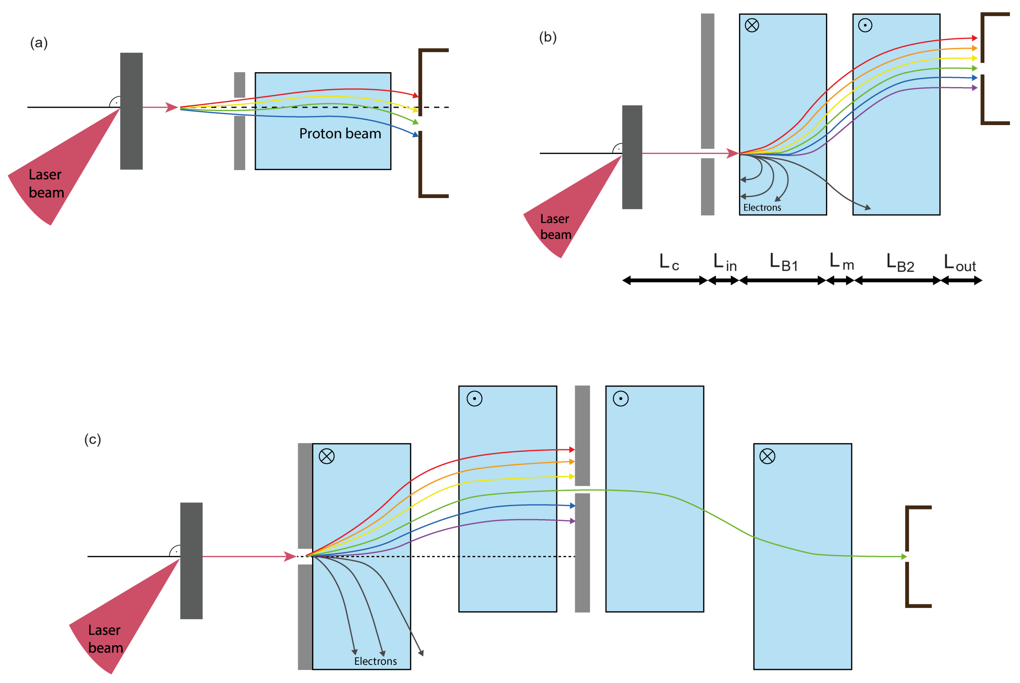
Figure 2.
(a) Exploded view of the energy selector. (b) 2D field map on the central plane; the red rectangle indicates the space between the pole shoes.
Figure 2.
(a) Exploded view of the energy selector. (b) 2D field map on the central plane; the red rectangle indicates the space between the pole shoes.
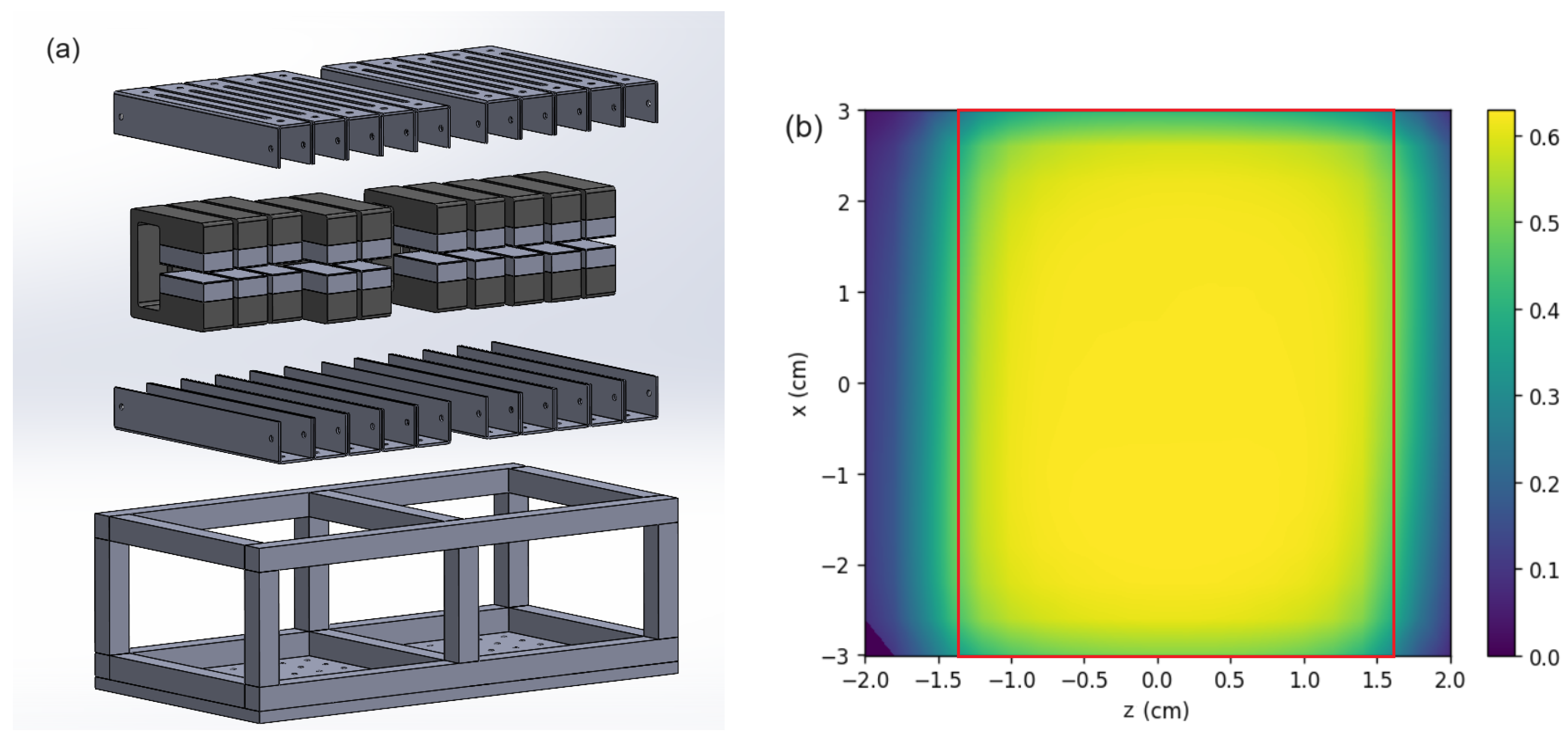
Figure 3.
(a) Energy selector at the external beamline of the CNA cyclotron. (b) Positions of the C-magnets for the 5+4 configuration (top view).
Figure 3.
(a) Energy selector at the external beamline of the CNA cyclotron. (b) Positions of the C-magnets for the 5+4 configuration (top view).
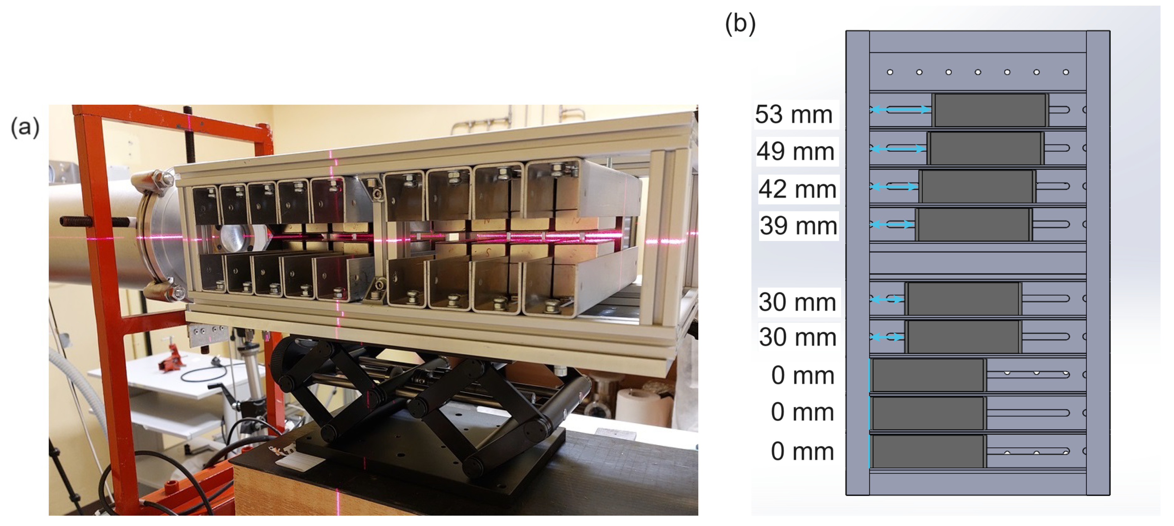
Figure 4.
(a) RCF sheets with beam spots indicating lateral hit positions. (b) Comparison of measured positions (dots) with simulated proton trajectory.
Figure 4.
(a) RCF sheets with beam spots indicating lateral hit positions. (b) Comparison of measured positions (dots) with simulated proton trajectory.
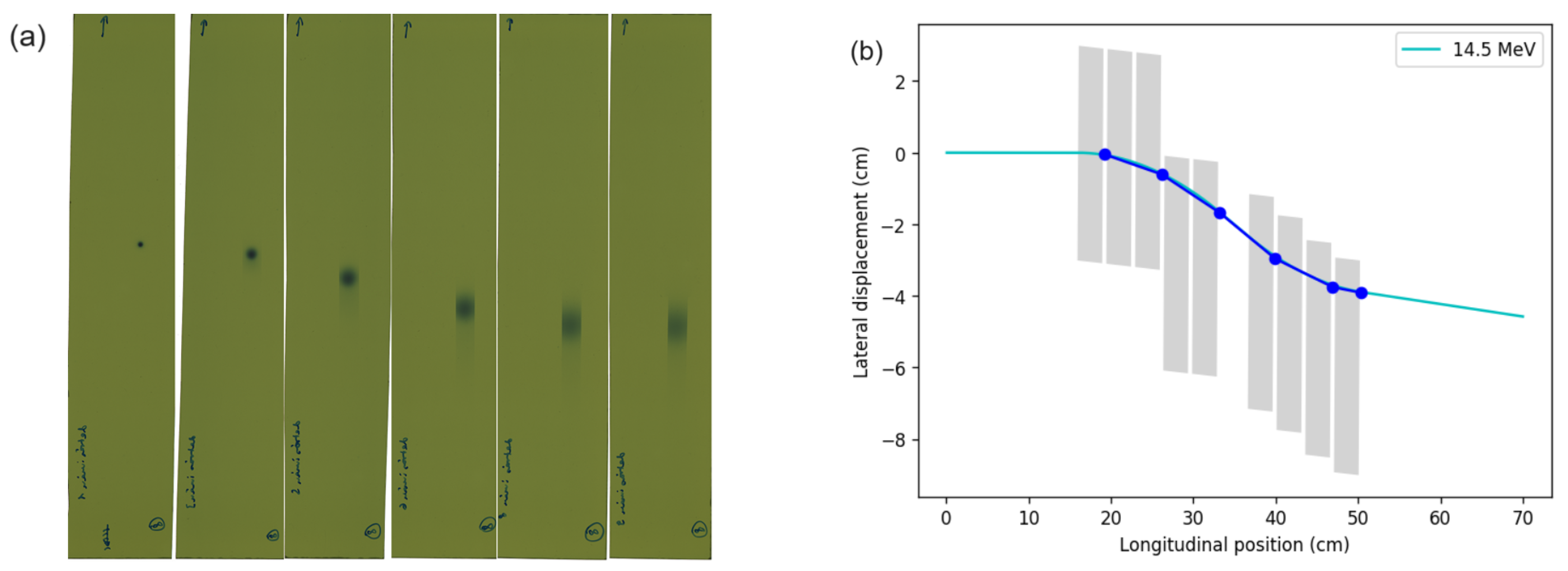
Figure 5.
Energy selector and proton trajectories with the 5+4 configuration inside the VEGA-3 target chamber.
Figure 5.
Energy selector and proton trajectories with the 5+4 configuration inside the VEGA-3 target chamber.
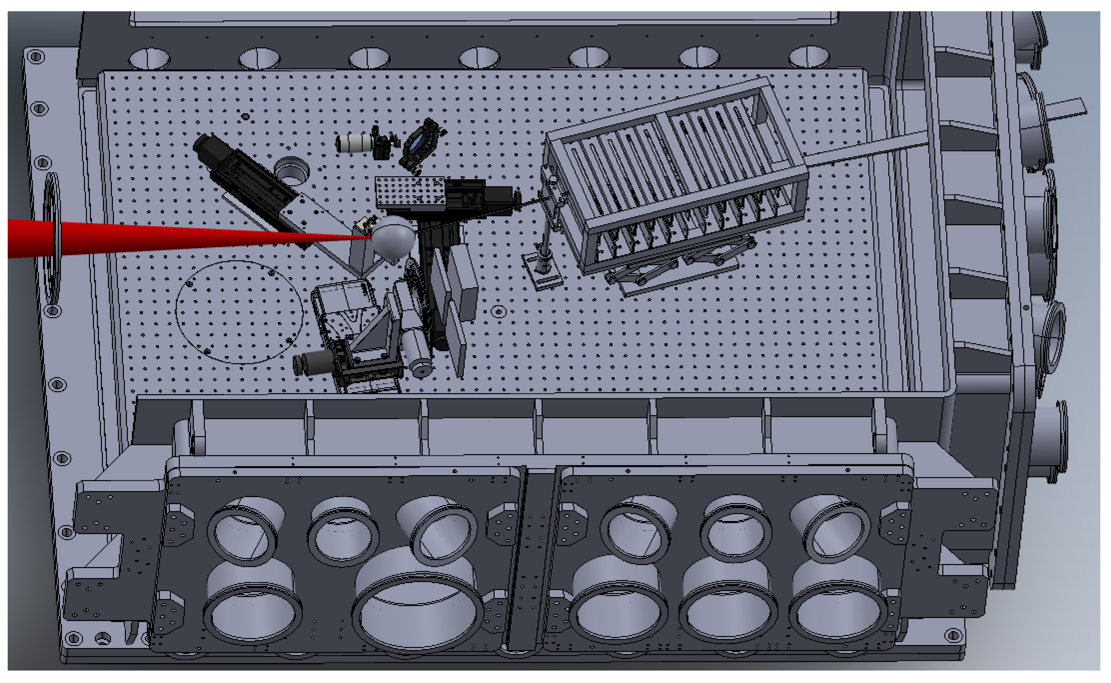
Figure 6.
Simulated proton trajectories inside the VEGA-3 target chamber for an alternative, 5+0 configuration of the selector.
Figure 6.
Simulated proton trajectories inside the VEGA-3 target chamber for an alternative, 5+0 configuration of the selector.
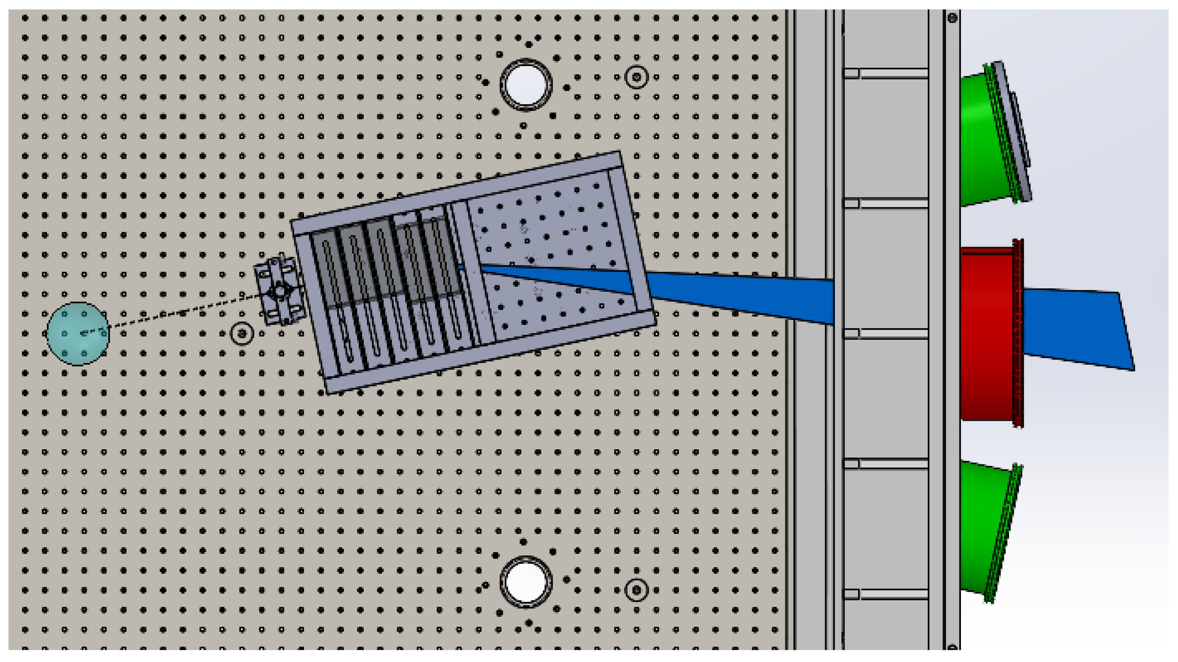
Figure 7.
Simulated energy distributions of protons at three positions of the vacuum window: mm (blue), mm (red), mm (black).
Figure 7.
Simulated energy distributions of protons at three positions of the vacuum window: mm (blue), mm (red), mm (black).
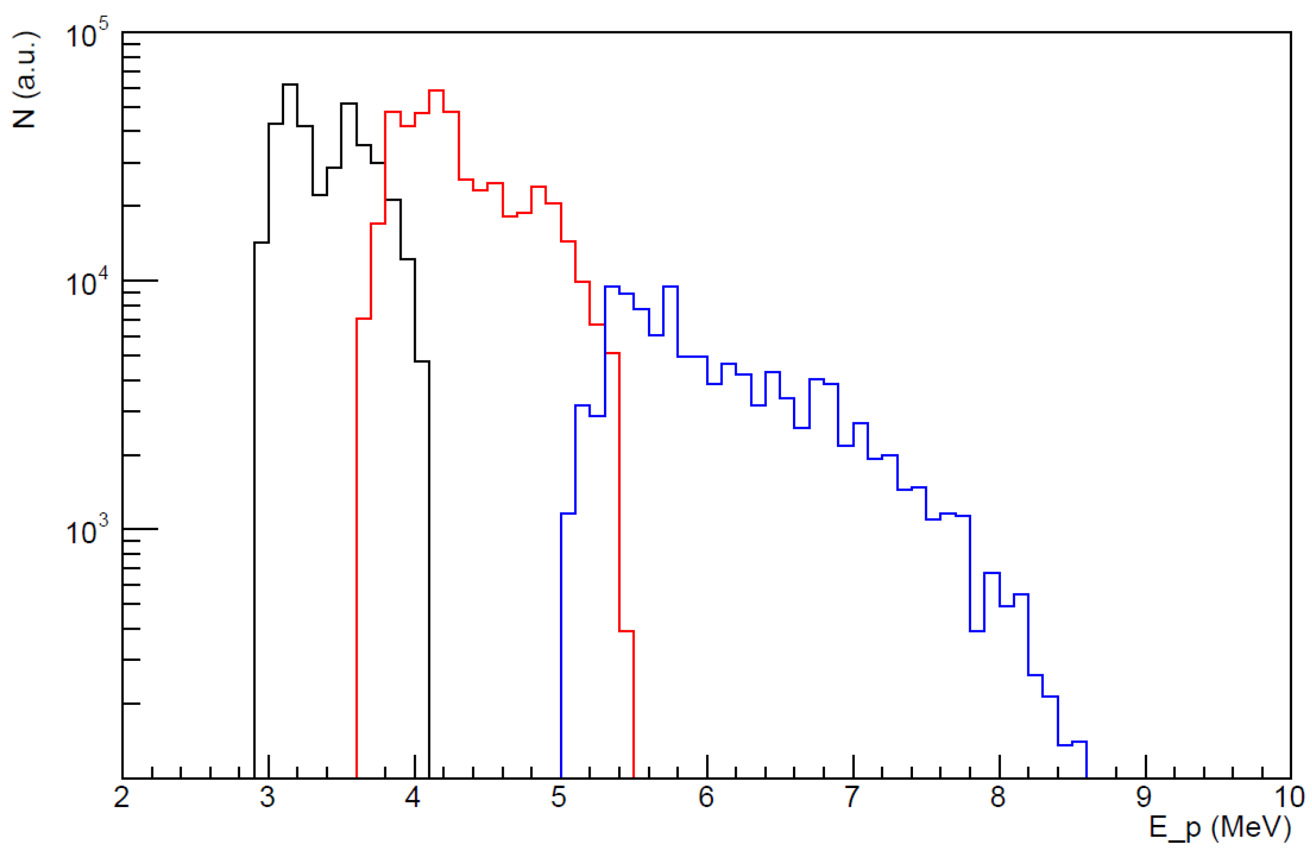
Figure 8.
(a) Oscilloscope signals from a time-of-flight detector and (b) reconstructed proton spectra. Colors indicate data taken with direct target view (blue, left scales) or with the energy selector inserted (red, right scales).
Figure 8.
(a) Oscilloscope signals from a time-of-flight detector and (b) reconstructed proton spectra. Colors indicate data taken with direct target view (blue, left scales) or with the energy selector inserted (red, right scales).
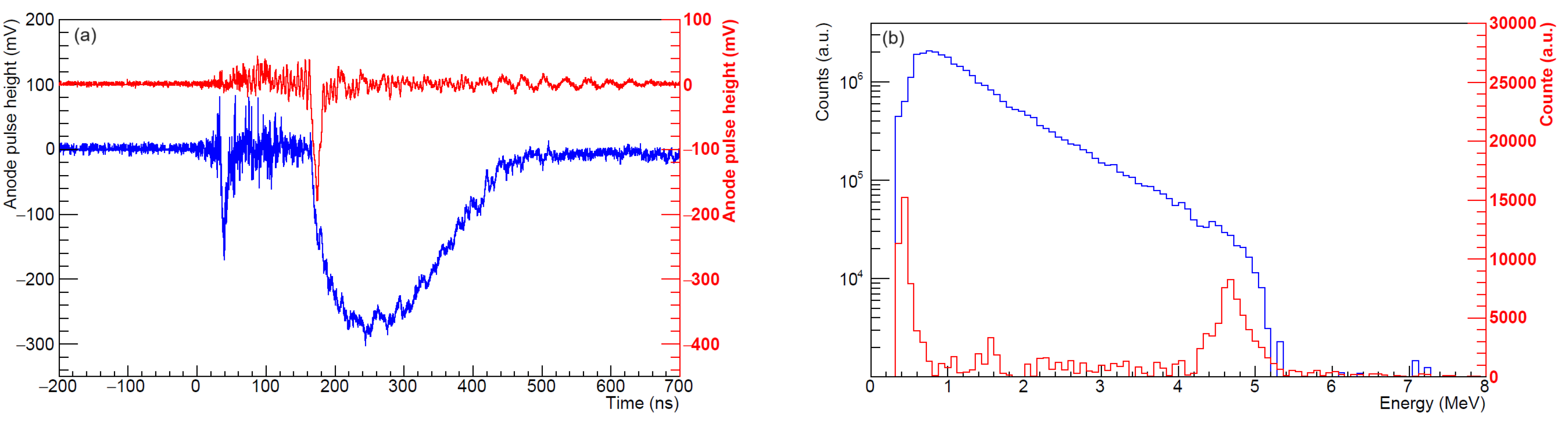
Figure 9.
(a) Transmission scan image of RCF stack on the vacuum window exposed to 20 laser shots. (b) Measured dose distributions in horizontal direction; arrows indicate positions of maximum deflection for protons with minimum energies to reach the sensitive layers.
Figure 9.
(a) Transmission scan image of RCF stack on the vacuum window exposed to 20 laser shots. (b) Measured dose distributions in horizontal direction; arrows indicate positions of maximum deflection for protons with minimum energies to reach the sensitive layers.
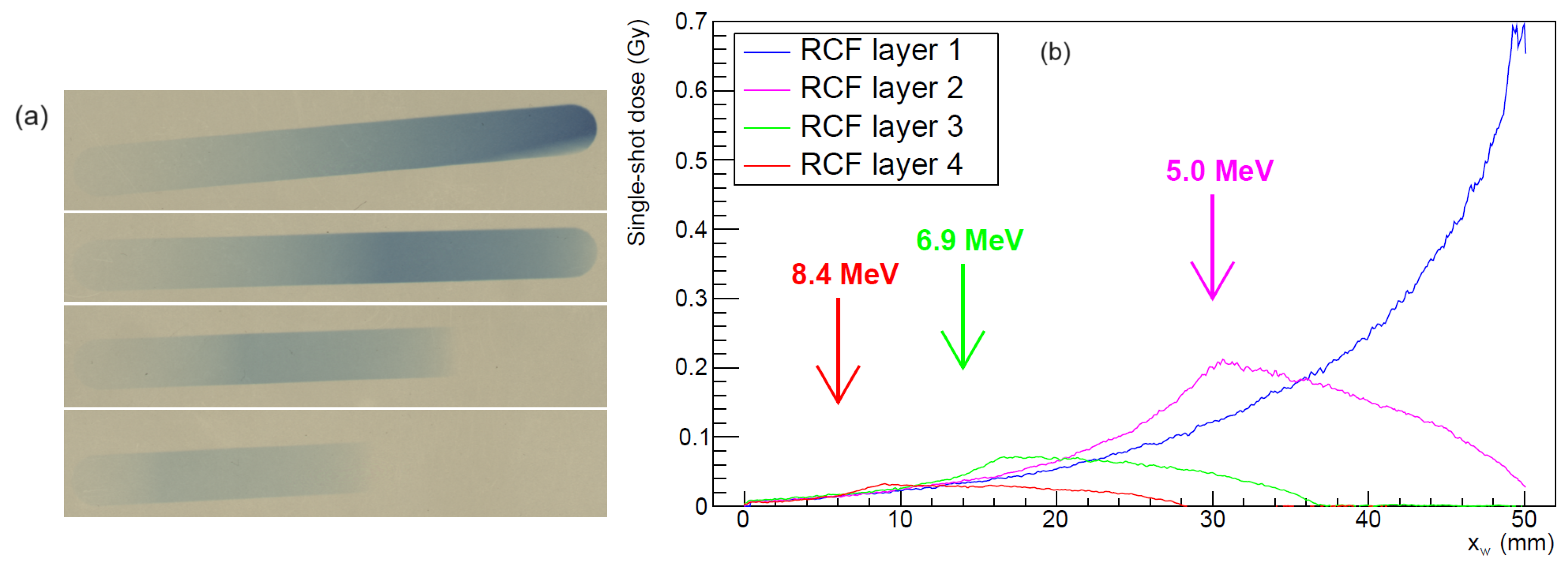
Figure 10.
Proton spectra retrieved at two horizontal positions on the vacuum window: (a) mm, (b) mm. Data refer to the RCF stack of Figure 9.
Figure 10.
Proton spectra retrieved at two horizontal positions on the vacuum window: (a) mm, (b) mm. Data refer to the RCF stack of Figure 9.
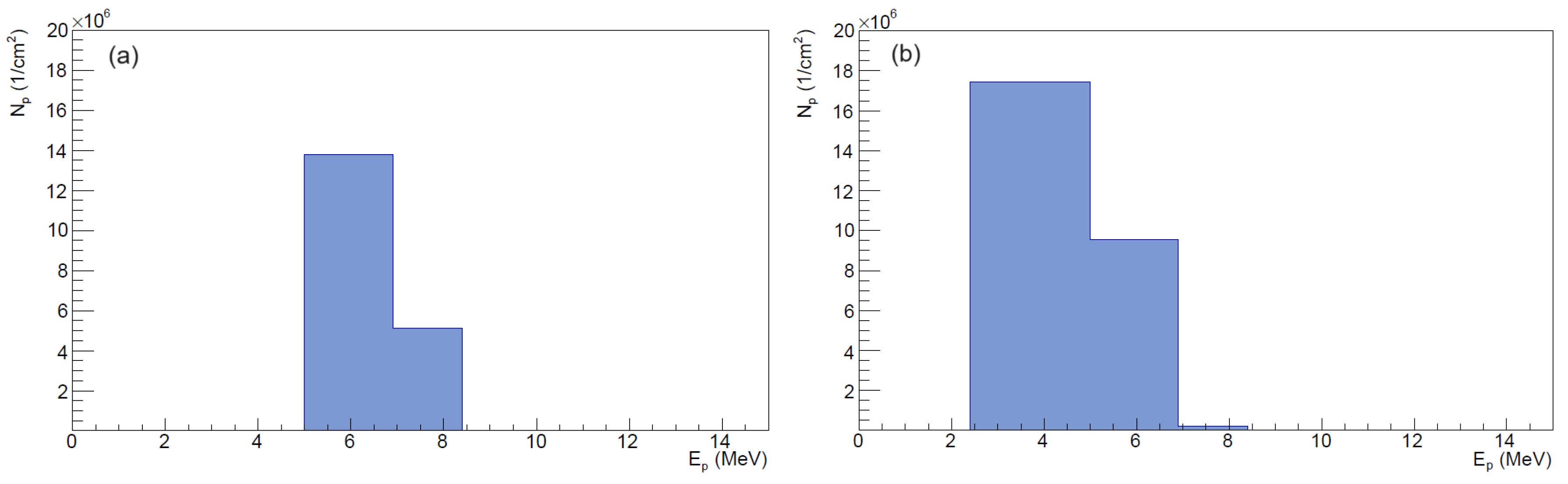
Figure 11.
(a) Transmission scan image of five PADC plates after a single laser shot. (b) Microscope image of plate 123.
Figure 11.
(a) Transmission scan image of five PADC plates after a single laser shot. (b) Microscope image of plate 123.
Disclaimer/Publisher’s Note: The statements, opinions and data contained in all publications are solely those of the individual author(s) and contributor(s) and not of MDPI and/or the editor(s). MDPI and/or the editor(s) disclaim responsibility for any injury to people or property resulting from any ideas, methods, instructions or products referred to in the content. |
© 2024 by the authors. Licensee MDPI, Basel, Switzerland. This article is an open access article distributed under the terms and conditions of the Creative Commons Attribution (CC BY) license (http://creativecommons.org/licenses/by/4.0/).
Copyright: This open access article is published under a Creative Commons CC BY 4.0 license, which permit the free download, distribution, and reuse, provided that the author and preprint are cited in any reuse.


