
Submitted:
11 October 2025
Posted:
13 October 2025
You are already at the latest version
Abstract
This study explores the application of lattice structures as internal support architectures in the fabrication of Inconel 718 components via Laser Powder Bed Fusion (L-PBF), building upon previous research on beam-based FCCZ supports. Two representative lattice typologies were investigated: the node and beam-based FCCZ structure and the triply periodic minimal surface (TPMS) Schoen Gyroid cell. The aim was to assess how the transition from a discrete beam-node architecture to a continuous surface topology influences manufacturability, thermal stability, and mechanical performance. Finite Element Method (FEM) simulations in Ansys accurately predicted distortions and residual stresses during the L-PBF process, showing strong agreement with stereomicroscope measurements. After fabrication, the samples underwent solution treatment and double aging according to AMS 2774 and AMS 5662 standards. Microstructural analysis using optical microscopy (OM), scanning electron microscopy (SEM), and transmission electron microscopy (TEM) revealed that heat treatment partially homogenized the microstructure but did not achieve complete recrystallization, leaving localized dendritic regions and undissolved Laves phases, particularly near the lattice. The precipitation of γ′ and δ phases enhanced hardness and mechanical uniformity, as confirmed by Vickers microhardness testing. Overall, the Gyroid topology demonstrated superior manufacturability and thermal stability, exhibiting reduced defects and deformation compared to the FCCZ structure. These findings confirm its potential as an efficient and reliable self-supporting architecture for L-PBF Inconel 718 components intended for high-performance and thermally demanding applications.
Keywords:
L-PBF
; TPMS
; Inconel 718
; FEM analysis
; heat treatment
; microstructural analysis
1. Introduction
According to the regulatory committees ASTMF42 and ISOTC261, powder bed fusion (PBF) and direct energy deposition (DED) are the primary metal additive manufacturing (MAM) technologies [1]. These processes involve the melting of raw material, usually in the form of micrometric powder. Laser Powder Bed Fusion (L-PBF) is particularly noteworthy in the field of MAM because it can produce high-performance metallic parts by melting metal powder layer by layer using a high-precision laser beam. The L-PBF process has a high degree of flexibility, allowing the creation of customised parts and the production of geometries with intricate details, and near-net-shape accuracy [2,3]. Owing to its high spatial resolution and process controllability, L-PBF is particularly effective in manufacturing lattice structures, which are increasingly applied in aerospace, biomedical, and energy sectors due to their excellent strength-to-weight ratio, high surface area, and enhanced heat transfer performance [4,5,6,7,8]. These structures allow for significant reductions in component weight and raw material consumption while offering design flexibility and functional optimization, such as improved thermal management and vibration damping [9]. Inconel 718 is a nickel-based superalloy known for its exceptional mechanical properties, including high creep and fatigue resistance at elevated temperatures, making it ideal for applications like jet engines and gas turbines [10]. It is widely used in additive manufacturing, especially L-PBF, due to its resistance to strain-age cracking during post-weld heat treatment [11,12]. The L-PBF process creates a complex microstructure in Inconel 718, featuring an austenitic γ matrix and various secondary phases like γ’ (Ni3(Al, Ti)), γ” (Ni3Nb), and δ (Ni3Nb) [13]. These phases are crucial for the alloy’s strength but can also reduce ductility and corrosion resistance. Heat treatments, such as solution treatment and aging, are essential to optimize the microstructure by promoting the precipitation of γ’ and γ” phases, thereby enhancing the material’s mechanical performance [14].
The primary aim is to assess the adaptability of geometric variables in fabricating lattice specimens via L-PBF to achieve specific mechanical and microstructural characteristics. Specifically, the study focuses on two representative lattice typologies: the node and beam-based FCC-Z structure and the triply periodic minimal surface (TPMS) Schoen Gyroid cell. The comparison aims to elucidate how the discrete node-and-beam framework of the FCCZ structure contrasts with the continuous surface morphology of the Gyroid lattice in terms of printability, process stability, thermal management, and mechanical behavior after heat treatment.
Building upon the findings of a previous investigation [15], which demonstrated the manufacturability and functional advantages of FCCZ beam-based supports in L-PBF, this study extends the analysis toward a direct comparison with Gyroid structures. The latter are recognized for their intrinsic self-supporting capability and high thermal dissipation efficiency, properties that make them particularly suitable for integration as internal support architectures in critical components, such as those used in aerospace or high-temperature applications.
While FCCZ lattices have been shown to provide an advantageous balance between thermal management and ease of post-processing removal due to their beam-based design, the Gyroid topology, defined by a continuous and smooth minimal surface, offers superior geometric continuity and mechanical load distribution, which can improve process stability during printing and enhance component reliability under service conditions. This study, therefore, aims to identify the trade-offs between these two lattice architectures and to establish design and processing guidelines for optimizing manufacturability, post-processing efficiency, and in service performance of Inconel 718 lattice-based support for high-performance and thermally demanding applications.
A Design of Experiments (DoE) approach was adopted, systematically varying geometric parameters such as cell size and beam diameter to assess their influence on manufacturability and structural integrity. Finite Element Method (FEM) simulations were conducted in ANSYS Workbench to predict distortions and residual stresses throughout the printing process and after component removal from the build plate, providing a virtual framework for understanding deformation mechanisms.
The printed specimens were subjected to solution treatment followed by double aging in accordance with aerospace standards AMS 2774 and AMS 5662 to evaluate the effects of heat treatment on phase evolution, recrystallization behavior, and strengthening mechanisms. Comprehensive microstructural characterization was carried out on both as-built (AB) and heat-treated (HT) samples, using optical microscopy (OM), scanning electron microscopy (SEM), and transmission electron microscopy (TEM), complemented by Vickers microhardness testing.
This multi-scale approach enables a robust correlation between lattice topology, microstructural features (including γ’, δ, and Laves phase distributions), and resultant mechanical properties. By integrating numerical simulation, experimental validation, and microstructural analysis, the present work provides new insights into the interplay between lattice geometry, process parameters, and post-processing conditions, supporting the development of optimized L-PBF Inconel 718 lattice supports in critical engineering applications.
2. Materials and Methods
In this study, nTopology software was used to model lattice specimens with a TPMS Gyroid unit cell pattern, while Siemens NX was used for specimens with an FCCZ unit cell pattern. The lattice specimens featured variable geometric parameters, including cell size and strut diameter (or wall thickness for Gyroid cells). Figure 1 (a, c) present the three-dimensional models of the FCCZ and Gyroid unit cells, respectively. Three lattice specimens were modelled for each cell topology, with unit cell volume varying over time due to changes in strut diameter keeping cell size constant. These variations are detailed in Table 1. The lattices measured 8x8x8 mm, with each specimen having a top plate thickness of 3 mm and a bottom plate thickness of 0.8 mm. The lattice structures were not fabricated directly on the construction platform to ensure adequate heat dissipation during the manufacturing process via the bottom plate.
The CAD models of the samples with the respective ID code are shown in Figure 1 (b, d).
Based on the observations reported in the previous study [15], samples A2F and B2F were excluded from further analysis due to the presence of defects and surface damage revealed during preliminary SEM inspection. Consequently, samples A2G and B2G were also not considered, as their inclusion would have prevented a direct comparison between the two lattice topologies under identical geometric parameters. Therefore, the comparative mechanical and metallographic characterizations were focused exclusively on samples C2F and C2G.
FEM simulations of the printing process for these samples were performed using Ansys Additive suite Workbench 2020 R1, which facilitates virtual prototyping under various conditions. The software can simulate mechanical deformations from thermal effects or incorporate explicit thermal phenomena. The simulations used the nominal STL files of the CAD models and L-PBF process parameters, with the model divided into tetrahedrons, following the basic software settings outlined in Table 2. All the process parameters listed in the table and implemented in the simulation are consistent with those employed in the LPBF process, corresponding to the default EOS M290 DMLS parameters for Inconel 718 [15,16].
In detail, the simulations carried out considered the following phases: printing, cooling and cutting of the part from the build plate, to qualitatively verify that the virtual model in Ansys gives strain and residual stress values comparable to the real ones.
The samples were fabricated on an EOS M250 L-PBF machine using atomised Inconel 718 powder as the feed stock. The following table (Table 3) shows the chemical composition in weight percentage (wt%) of Inconel 718, as given in the EOS technical data sheet [17].
The L-PBF process was performed with laser power and scanning speed according to the predefined core-skin scanning pattern as shown in Table 2, where the values of the process parameters set not only for the simulation but also for the sample printing are shown. A laser spot of 0.08 mm was used, and an inert gas atmosphere of argon was established. The heating of the build platform was set to 80 °C.
To compare the manufactured samples with the respective simulated models, observations of the profile of the top plate and measurements using a Leica stereomicroscope (model DVM6) were carried out to assess the profile and the magnitude of the distortion along the growth direction (Z-direction) caused by the manufacturing process.
Two metallographic samples were taken from both the C2F and C2G components by cutting them in half along the growth direction (YZ plane) using an electric discharge machine. For each of them, one sample was left in the as built condition while the other was subjected to a heat treatment to investigate the differences in mechanical and microstructural behaviour between the two conditions. Specifically, a solution annealing followed by double aging was carried out as described in the AMS 2774 and AMS 5662 aerospace materials specifications. In detail, the process involves heating to 954 °C for 1 hour, cooling in air, followed by a second heating phase at 718 °C with a dwell time of 8 hours at this temperature. This is followed by further oven cooling to 621 °C, dwelling at 621 °C for a total precipitation time of 18 hours, and finally air cooling to room temperature.
For metallographic investigation, the YZ surfaces of the as built (C2F-AB and C2G-AB) and heat treated (C2F-HT and C2G-HT) samples were mechanically polished with silicon carbide paper up to 4000 grit and then mirror polished with diamond paste up to 0.25 µm. To characterise the microstructure of the alloy before and after heat treatment, the samples were subjected to chemical etching at room temperature using the following solution: 28 ml acetic acid, 28 ml nitric acid, 44 ml hydrochloric acid. Observations under an optical microscope were carried out using a Leica DMi8 instrument to highlight the microstructural features.
To further characterise the microstructure of L-PBF fabricated Inconel 718 and its evolution after heat treatment, SEM analyses were performed using a Zeiss Supra 40 field emission microscope equipped with a Bruker Quantax Z200 microanalysis system. TEM characterization was conducted using a Philips CM200 transmission electron microscope operating at 200 kV, equipped with a nitrogen-cooled, double-tilt sample holder. Phase and constituent identification were achieved through SAEDP indexing, performed using CaRIne Crystallography 3.1 software. Thin discs for TEM analysis were mechanically prepared by polishing and thinning both sides to 25-35 µm, followed by ion milling with a Gatan PIPS using Ar+ at gradually decreasing angles from 8° to 4°, to ensure sufficient electronic transparency. To ensure statistical reliability, three different discs were examined for each experimental condition.
Vickers microhardness measurements were carried out on all samples under both AB and HT conditions using a QNESS 60 A+ EVO automatic microhardness tester, with an applied load of 300 gF and a dwell time of 10 seconds, to assess local mechanical behaviour across various surface positions. Systematic indentations were made on the upper plate of each specimen and along the lattice structures of selected samples. The study aimed to compare mechanical properties between the lattice structures and the bulk material, as well as to evaluate the effects of heat treatment. The average microhardness values and standard deviations were reported for all samples.
3. Results and Discussion
3.1. FEM Analysis
Figure 2 (a, b) presents the results of the FEM analysis conducted using Ansys® Workbench 2020 R1. The results are expressed in terms of directional deformations measured along the z-axis, at the end of the printing phase and after the removal of the component from the build plate. Specifically, Figure 2 (a, b) highlight markers indicating the maximum directional deformation along the z-axis (in mm) measured in the interface region between the lattice structure and the upper plate, particularly near the edges, where significant distortion of the plate is observed. The maximum directional deformation recorded is 0.32 mm for the C2F sample, while the C2G sample exhibits a maximum deformation of 0.17 mm. It is therefore evident that the C2F sample exhibits the most significant distortions, as it has a lattice structure that is more compliant than that of the C2G sample. Consequently, it is less effective at dissipating the heat generated during the printing process. It should be noted that the simulation results for the C2F sample have already been presented and discussed in [15].
After the components were removed from the build plate, the maximum stress reached was approximately 1328 MPa for the C2F sample (Figure 2 (c)) and 940 MPa for the C2G sample (Figure 2 (d)), with both samples showing this peak stress in the interface region between the lattice structure and the upper plate. While the maximum stress observed in the C2G sample remains acceptable, as it does not exceed the yield strength of Inconel 718, which ranges from 724 MPa to 1241 MPa, the C2F sample exceeds this yield strength, indicating the possibility of permanent plastic deformation. This could increase the risk of cracks or defects in the affected area, especially if there are local variations in process conditions or microstructure. Therefore, post-processing heat treatment may be necessary to reduce residual stresses and prevent excessive deformation during component removal.
3.2. FEM Analysis vs. Experimental Results
The comparison between the simulated models and the printed geometries was conducted through stereomicroscope observations. The deformation profile of a portion of the upper plate was extracted, and directional deviations were measured at specific points on the upper plate along the XY plane. The results, presented in Figure 3, demonstrate a robust correlation between the simulated models and the real components regarding both the deformation trend and the numerical values of directional deformations (along the Z-axis) measured in the XY plane of the upper plate, confirming the reliability of the software used. In both the C2F and C2G samples, a slight curvature of the plate towards the negative Z direction was observed, resulting in compression of the upper surface. A reversal in the deformation trend is observed, with the deformation increasing in magnitude from the central area towards the edges of the plate. The extent of deformation was quantified at specific points on the plate in both the simulated models and the corresponding points on the actual samples. The upward curvature in the negative Z direction of the upper plate in the C2F sample (Figure 3 (a)) is more pronounced than that observed in the upper plate of the C2G sample (Figure 3 (b)), as indicated by the deformation values expressed in mm. The increased distortion observed in the C2F sample can be attributed to its less massive FCCZ lattice structure, which is less effective at dissipating the heat generated during the manufacturing process than the Gyroid structure.
3.3. Assessment of Microstructural and Mechanical Behaviour in As-Built and Heat-Treated Conditions
As shown in Figure 4 (a), the microstructure observed on the upper plate of the C2G-AB sample along the YZ plane highlights the arc shape of the melt pools created by the laser during the scanning of the powder bed, with partial overlap due to the rotation of the laser beam by 67° per pass. Heat dissipation from the melt zone to the platform leads to the formation of columnar grains aligned along the Z-axis, visible at low magnification, which pass through successive layers of powder due to multiple remelting and epitaxial growth. Figure 4 (b) shows the microstructure observed on the top plate of C2G-HT sample, highlighting a partial recrystallisation induced by the heat treatment, with disappearance of the melt pools but only partial dissolution of the dendritic structures. The static recrystallisation results in columnar grains along the z-axis, but the temperature is not sufficient to promote the formation of equiaxial grains. Since the upper plate of the C2F sample exhibited microstructural features identical to those of C2G in both the as-built and heat-treated conditions, its micrographs are not presented here. A detailed discussion of these microstructural findings can be found in reference [15].
The micrograph along the YZ plane in a region of the lattice structure of the C2F-AB sample (Figure 5 (a)) shows that the porosities, although randomly distributed along the whole lattice, are more diffuse and characterised by larger voids in the area close to the nodes, due to the rapid change in thermal diffusivity during the production process as different struts are joined together. This result is in line with expectations, since the sudden changes in cross-sectional area (YZ plane) that occur during the printing phase of the component lead to significant instability phenomena in the melt pool. The porosities are localised within the melting pools, as can be seen from the micrographs in Figure 5 (a), and most of these are keyhole-type porosities [15]. The formation of keyhole-type melting pools is usually due to excessive energy being absorbed by the powder bed, resulting in the laser beam penetrating too deeply. The formation of deep melting pools can also be attributed to Marangoni flow, which is melt flow from the hot centre to the edges of the pool due to the difference in surface tension induced by the strong thermal gradient. This was also confirmed by the work of Salem et al [18], where microstructural analysis showed deep melting pools under keyhole conditions at high laser powers and relatively low scan speeds. The presence of few small spherical porosities can also be detected, which is mainly due to the gas trapped in the powder bed during the production process [15]. Figure 5(b) shows that sample C2G-AB exhibits no significant porosity near the lattice region.
The variation in defect rates in L-PBF lattice samples fabricated with identical process parameters can be attributed to differences in lattice cell geometries and their impact on heat distribution, laser penetration, and residual stresses. The FCCZ cell, with its geometry that can lead to non-uniform heat distribution, tends to cool faster in certain areas, resulting in heterogeneous solidification and keyhole-type defects. In contrast, gyroid cells, with their continuous and more massive structure, promote uniform heat distribution, controlled solidification, and fewer defects. Additionally, energy density and laser penetration differ between lattice geometries; the FCCZ structure can cause irregular laser absorption, while the more massive gyroid structure tends to achieve uniform absorption. Residual stresses, which are higher in intricate geometries like FCCZ, further contribute to defect formation, whereas gyroid structures distribute these stresses more evenly, reducing defect occurrence. In sample C2F, heat treatment resulted in differential recrystallization within the same component. Specifically, due to the different thermal inertia between the plate and the lattice structure, variations in heat distribution occurred during the heat treatment. The lattice structure, with its larger exposed surface area compared to the solid upper plate, likely experienced different heating and cooling rates during the heat treatment. In detail, Figure 6 (a) illustrates that the microstructure observed in a region of the lattice structure of C2F-HT sample shows less recrystallization and retains more non-equilibrium dendritic structures compared to the upper plate’s microstructure shown in Figure 4 (b). These results, both in the as-built and heat-treated conditions, were previously documented and discussed in detail in [15]. This uneven recrystallization affects the material’s microstructure and mechanical properties, potentially impacting the overall performance of the component. For the same reasons, similar microstructural differences are observed between the C2F-HT and C2G-HT samples. Specifically, the heat treatment induced a lower degree of recrystallization in the lattice of the C2F sample, as shown in Figure 6(a), compared to the lattice region of the C2G-HT sample in Figure 6(b). This indicates that the C2F lattice exhibited a distinct thermal response to heat treatment, leading to a greater retention of dendritic structures in the C2F-HT sample.
Figure 7 (a) presents a low-magnification SEM image of the upper plate area of the C2G-AB sample, revealing a very fine cell-dendritic microstructure. In this region, the secondary arms of the dendritic structures are entirely suppressed, allowing only the primary arms to develop. As observed in the micrographs in Figure 4 (a) and in Figure 5, as well as in the SEM image in Figure 7 (a), the growth directions of the dendrites are not perfectly parallel to the build direction but are instead inclined by a few degrees. Additionally, within a single melt pool, cell dendrites can grow in various directions and may be interrupted by adjacent cell dendrites, a phenomenon also reported in the literature by Deng et al. [19]. The variation in the size and orientation of these solidifying cell substructures is driven by the high temperature gradient and rapid cooling rate characteristic of the L-PBF process. As a result, the growth orientation of the dendrites aligns with the direction of the maximum temperature gradient. This indicates that the temperature field within the melt pool is highly complex, with turbulent motion inducing a reversal of the thermal gradient. Figure 7 (b) presents a bright-field (BF) TEM image of sample C2G-AB, revealing thin cell substructures with a high density of dislocations concentrated along the cell walls. The dark, irregularly shaped block-like precipitates observed near the grain boundaries, as indicated by the arrows in Figure 7 (b), have been identified as Laves phases.
The SEM image in Figure 8 (a) illustrates that in the C2G-HT sample, compared to the C2G-AB sample, the boundaries of the melt pools and many directional dendritic microstructures have been dissolved. Several needle-like δ (Ni₃Nb) phases are present within the grains and along the grain boundaries, with some precipitates also found in the interdendritic regions, as indicated by the black rectangles in Figure 8 (a). This observation aligns with findings reported in the study by Li et al. [20]. The formation of interdendritic δ precipitates preserves the visibility of the intragranular columnar structure after heat treatment. SEM imaging also identifies other precipitated phases, likely γ’ (Ni₃ (Al, Ti)) phases, which may form within the γ matrix both inside grains and near grain boundaries, with an acicular morphology. The γ’ phases reinforce the γ matrix, while the δ phases, precipitating at grain boundaries, act as barriers to dislocation movement, enhancing resistance to deformation at high temperatures and under sustained loads. However, the presence of undissolved Laves phases in the matrix can adversely affect mechanical properties by depleting Nb content, which reduces the potential for γ’ and γ” strengthening phase precipitation, and by serving as initiation sites for crack propagation, compromising structural integrity and accelerating service failure. These observations of precipitated phases in the C2F-HT sample partially align with the findings presented in the research by Li et al. [20] and Zhang et al. [21]. Consequently, this microstructure cannot be considered ideal. The TEM bright-field (BF) micrograph in Figure 8(b), together with the corresponding SAED patterns shown as inset, confirms the identification of the precipitated phases. This method is essential for distinguishing phases based on their crystal structure, as many of the precipitates observed in SEM are morphologically and compositionally similar. The cellular structures highlighted in both light and dark colours in Figure 8 (b) represent the γ matrix, but with different crystallographic orientations.
SEM and TEM analyses performed on a localized area of the upper plate of sample C2F revealed microstructural features identical to those observed in the corresponding region of sample C2G. For this reason, the related results are not reproduced here, as they have already been comprehensively presented and discussed in [15].
For the C2F-AB sample, the average microhardness on the upper plate is 308±16 HV, with values higher near the edge and interface with the lattice and lower towards the core [15]. The C2G-AB sample shows a higher average microhardness of 329±12 HV. In the HT condition, both C2F and C2G samples exhibit similar microhardness values of approximately 497±10 HV. The greater standard deviation in AB samples, compared to HT ones, is due to a less uniform microstructure, residual stresses, printing defects, and thermal fluctuations. Heat treatment enhances microstructural uniformity, reduces residual stresses, and minimizes defects, resulting in lower variability and standard deviation in microhardness.
Figure 9 (a) displays a column chart comparing average microhardness values and their standard deviations along the YZ plane for C2F-AB and C2F-HT samples, focusing on the upper plate, lattice nodes, and struts. Both AB and HT samples show distinct peaks in average microhardness, characterized by significant standard deviations, especially within the lattice structure. This variability is due to the presence of numerous pores introduced during manufacturing, particularly in the lattice structure, including the struts and nodes. Figure 9 (b) shows a bar chart of average microhardness values and standard deviations for the C2G sample along the upper plate and three lattice walls (one central and two near the edges) in the YZ plane, before and after heat treatment.
The increase in hardness observed in the heat-treated samples compared to the as-built condition is mainly due to significant phase precipitation resulting from heat treatment. This precipitation notably affects the material’s mechanical properties by reducing ductility and enhancing hardness. TEM micrographs (Figure 8 (b)) identify the predominant δ phases, with γ’ phases also contributing significantly. The γ’ phases precipitate during the double aging process at 718 °C and 621 °C, which strengthens the material and improves its mechanical properties, including hardness. Similar findings have been reported by Deng et al. [19] and Zhang et al. [21]. Implementing a high-temperature homogenization step or reducing the aging duration could promote the precipitation of the γʺ phase. Further studies are required to assess whether these modifications may enhance mechanical properties, including microhardness. Nevertheless, since this work strictly followed the heat treatment procedures prescribed by Aerospace Material Specifications AMS 2774 and AMS 5662, no conclusive evidence can be drawn beyond the observations reported in the referenced literature [15]. Additionally, Chamanfar et al. [22] observed that a small amount of δ phase can inhibit grain growth by pinning grain boundaries, which enhances strength and hardness through grain boundary strengthening [22]. However, excessive δ phase content can reduce strength, as it depletes Nb and hinders the precipitation of γ” strengthening phases.
4. Conclusions
This study extended the previous investigation on Inconel 718 lattice structures fabricated via L-PBF [15], focusing on a comparative assessment between beam-based FCCZ and TPMS-based Schoen Gyroid architectures. Building upon earlier results, where the FCCZ structure demonstrated suitability as an internal support for upper plates under specific geometric constraints, the present work broadened the analysis to include the Gyroid topology, with the aim of assessing its potential as an advanced support structure for complex geometries.
Finite Element Method (FEM) simulations performed in Ansys confirmed the capability of the software to accurately predict thermal and mechanical deformations both during the L-PBF process and after removal from the build platform. The close agreement between simulated geometries and stereomicroscopic measurements validated the reliability of the numerical approach.
Mechanical and microstructural characterization was carried out specifically on the C2F and C2G samples, both in the as-built and heat-treated conditions. The adopted heat treatment, consisting of solution treatment followed by double aging according to AMS 2774 and AMS 5662 specifications, led to the following main outcomes:
- Microstructural evolution: Post-heat treatment conditions did not enable complete recrystallization near the lattice region. Partial homogenization was achieved, but residual dendritic structures persisted within both the upper plate and lattice areas. The differences in thermal inertia between the solid plate and the open-cell lattice contributed to this heterogeneous recrystallization behavior.
- Precipitated phases: SEM and TEM analyses confirmed the formation of γ’ and δ phases after heat treatment, along with the persistence of limited Laves phase remnants. These phases can adversely affect ductility and local mechanical performance, suggesting that optimized solution temperatures or additional homogenization steps may be required to achieve full dissolution.
- Microhardness analysis: Vickers microhardness results showed increased hardness in the HT samples compared to the AB condition, attributed to the precipitation of strengthening phases. The HT condition also exhibited more homogeneous hardness values across both structures, indicating an improved and more uniform mechanical response.
When comparing the two lattice topologies, the Gyroid structure exhibited distinctive advantages over the FCCZ configuration. The TPMS-based continuous surface of the Gyroid ensured more uniform thermal gradients during fabrication, reducing local stress concentrations and deformation, as confirmed by FEM predictions and post-process measurements. Furthermore, its smoother curvature transitions and absence of sharp nodes improved powder flow and melt pool stability, mitigating defect formation and enhancing overall structural integrity. These features make the Gyroid topology particularly well-suited as an advanced self-supporting structure for L-PBF manufacturing of complex Inconel 718 components, where mechanical reliability and geometric accuracy are critical. Overall, this study confirms that TPMS-based designs, and specifically the Schoen Gyroid, represent a promising alternative to conventional beam-based lattices such as the FCCZ, combining mechanical robustness, improved manufacturability, and enhanced performance as internal supports for demanding applications.
Author Contributions
Conceptualization, A.S..; methodology, G.V. and K.S.; simulations, G.V. and A.S.; validation, E.S.; formal analysis, G.G.; investigation, G.G.; resources, M.C.; data curation, G.V., A.S. and G.G.; writing—original draft preparation, G.V. and E.S.; writing—review and editing, A.S. and M.C.; supervision, M.C.; project administration, M.C.. All authors have read and agreed to the published version of the manuscript.
Funding
Financed by the European Union-NextGenerationEU (National Sustainable Mobility Center CN00000023, Italian Ministry of University and Research Decree n. 1033-17/06/2022, Spoke 11- Innovative Materials & Lightweighting), and National Recovery and Resilience Plan (NRRP), Mission 04 Component 2 Investment 1.5-NextGenerationEU, Call for tender n. 3277 dated 30 December 2021. The opinions expressed are those of the authors only and should not be considered representative of the European Union or the European Commission’s official position. Neither the European Union nor the European Commission can be held responsible for them.
Data Availability Statement
The raw data supporting the conclusions of this article will be made available by the authors on request.
Acknowledgments
We acknowledge the valuable input from the anonymous reviewers of the manuscript, whose observations improved its quality.
Conflicts of Interest
The authors declare no conflicts of interest.
References
- Standard, A. S. T. M. (2012). Standard terminology for additive manufacturing technologies. ASTM International F2792-12a, 46, 10918-10928.
- DebRoy, T., Wei, H. L., Zuback, J. S., Mukherjee, T., Elmer, J. W., Milewski, J. O., & Zhang, W. (2018). Additive manufacturing of metallic components–process, structure and properties. Progress in materials science, 92, 112-224. [CrossRef]
- King, W. E., Barth, H. D., Castillo, V. M., Gallegos, G. F., Gibbs, J. W., Hahn, D. E., & Rubenchik, A. M. (2014). Observation of keyhole-mode laser melting in laser powder-bed fusion additive manufacturing. Journal of Materials Processing Technology, 214(12), 2915-2925. [CrossRef]
- Gibson, L. J. (2003). Cellular solids. Mrs Bulletin, 28(4), 270-274.
- Tamburrino, F., Graziosi, S., & Bordegoni, M. (2018). The design process of additively manufactured mesoscale lattice structures: a review. Journal of Computing and Information Science in Engineering, 18(4), 040801. [CrossRef]
- Maskery, I., Sturm, L., Aremu, A. O., Panesar, A., Williams, C. B., Tuck, C. J., & Hague, R. J. (2018). Insights into the mechanical properties of several triply periodic minimal surface lattice structures made by polymer additive manufacturing. Polymer, 152, 62-71. [CrossRef]
- Yan, C., Hao, L., Hussein, A., Bubb, S. L., Young, P., & Raymont, D. (2014). Evaluation of light-weight AlSi10Mg periodic cellular lattice structures fabricated via direct metal laser sintering. Journal of Materials Processing Technology, 214(4), 856-864. [CrossRef]
- Beyer, C., & Figueroa, D. (2016). Design and analysis of lattice structures for additive manufacturing. Journal of Manufacturing Science and Engineering, 138(12), 121014. [CrossRef]
- Catchpole-Smith, S., Sélo, R. R., Davis, A. W., Ashcroft, I. A., Tuck, C. J., & Clare, A. J. A. M. (2019). Thermal conductivity of TPMS lattice structures manufactured via laser powder bed fusion. Additive Manufacturing, 30, 100846. [CrossRef]
- Amato, K. N., Gaytan, S. M., Murr, L. E., Martinez, E., Shindo, P. W., Hernandez, J., & Medina, F. J. A. M. (2012). Microstructures and mechanical behavior of Inconel 718 fabricated by selective laser melting. Acta Materialia, 60(5), 2229-2239. [CrossRef]
- Calandri, M., Yin, S., Aldwell, B., Calignano, F., Lupoi, R., & Ugues, D. (2019). Texture and microstructural features at different length scales in Inconel 718 produced by selective laser melting. Materials, 12(8), 1293. [CrossRef]
- Chlebus, E., Gruber, K., Kuźnicka, B., Kurzac, J., & Kurzynowski, T. (2015). Effect of heat treatment on the microstructure and mechanical properties of Inconel 718 processed by selective laser melting. Materials Science and Engineering: A, 639, 647-655. [CrossRef]
- Kirka, M. M., Unocic, K. A., Raghavan, N., Medina, F., Dehoff, R. R., & Babu, S. S. (2016). Microstructure development in electron beam-melted Inconel 718 and associated tensile properties. Jom, 68(3), 1012-1020. [CrossRef]
- Wang, C., & Li, R. (2004). Effect of double aging treatment on structure in Inconel 718 alloy. Journal of Materials Science, 39(7), 2593-2595. [CrossRef]
- Santoni, A., Cabibbo, M., Mandolini, M., Palladino, M., Spigarelli, S., & Santecchia, E. (2025). Laser Powder Bed Fusion Inconel 718 Lattice Structures: From Process Simulation to Microstructural and Mechanical Characterizations. Metals and Materials International, 1-23. [CrossRef]
- Chen, Q., Liang, X., Hayduke, D., Liu, J., Cheng, L., Oskin, J., & To, A. C. (2019). An inherent strain based multiscale modeling framework for simulating part-scale residual deformation for direct metal laser sintering. Additive Manufacturing, 28, 40. [CrossRef]
- EOS Nikel Alloy IN718 Material Data Sheet.
- H. Salem, L.N. Carter, M.M. Attallah, H.G. Salem, Influence of processing parameters on internal porosity and types of defects formed in Ti6Al4V lattice structure fabricated by selective laser melting. Mater. Sci. Eng. A 767, 138387 (2019). [CrossRef]
- Deng, D., Peng, R. L., Brodin, H., & Moverare, J. (2018). Microstructure and mechanical properties of Inconel 718 produced by selective laser melting: Sample orientation dependence and effects of post heat treatments. Materials Science and Engineering: A, 713, 294-306. [CrossRef]
- Li, X., Shi, J. J., Wang, C. H., Cao, G. H., Russell, A. M., Zhou, Z. J., & Chen, G. F. (2018). Effect of heat treatment on microstructure evolution of Inconel 718 alloy fabricated by selective laser melting. Journal of Alloys and Compounds, 764, 639-649. [CrossRef]
- Zhang, D., Niu, W., Cao, X., & Liu, Z. (2015). Effect of standard heat treatment on the microstructure and mechanical properties of selective laser melting manufactured Inconel 718 superalloy. Materials Science and Engineering: A, 644, 32-40. [CrossRef]
- Chamanfar, A., Sarrat, L., Jahazi, M., Asadi, M., Weck, A., & Koul, A. K. (2013). Microstructural characteristics of forged and heat treated Inconel-718 disks. Materials & Design (1980-2015), 52, 791-800. [CrossRef]
- Barker, J. F. (1989). The initial years of alloy 718–A GE perspective. Superalloy, 718, 269-277.
- Yong, C. K., Gibbons, G. J., Wong, C. C., & West, G. (2020). A critical review of the material characteristics of additive manufactured IN718 for high-temperature application. Metals, 10(12), 1576. [CrossRef]
Figure 1.
CAD models of the unit cell (a) FCCZ and (c) Gyroid and of samples (b) A2F, B2F, C2F and (d) A2G, B2G, C2G.
Figure 1.
CAD models of the unit cell (a) FCCZ and (c) Gyroid and of samples (b) A2F, B2F, C2F and (d) A2G, B2G, C2G.
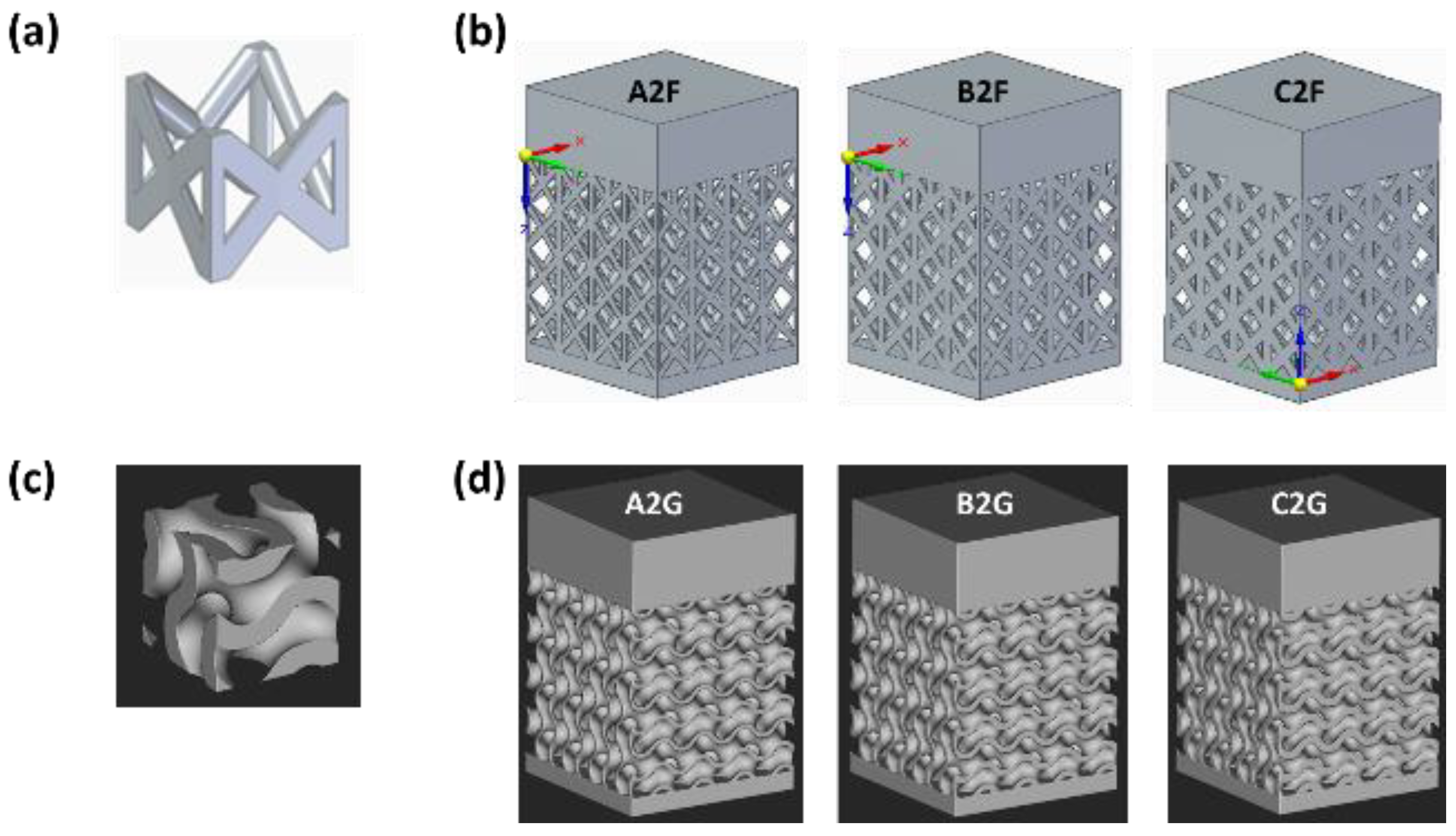
Figure 2.
FEM results showing (a) and (b) the maximum directional deformation (along the z-axis) expressed in mm for samples C2F and C2G, respectively, and (c) and (d) the Von Mises equivalent stress (MPa) for C2F and C2G after removal from the build plate.
Figure 2.
FEM results showing (a) and (b) the maximum directional deformation (along the z-axis) expressed in mm for samples C2F and C2G, respectively, and (c) and (d) the Von Mises equivalent stress (MPa) for C2F and C2G after removal from the build plate.
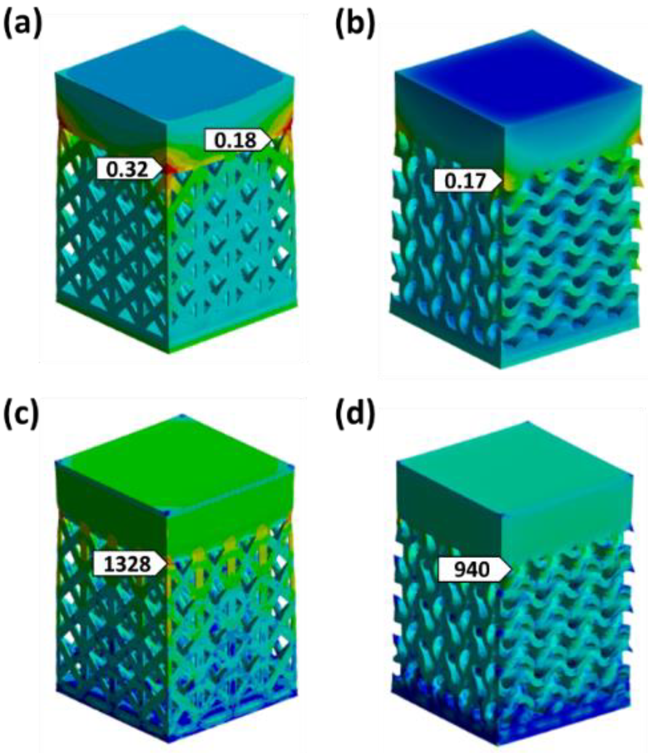
Figure 3.
Comparison of directional deformations along the Z-axis, measured in millimeters, between the Ansys model and the real geometry (stereomicroscope measurements) for the upper plate of samples (a) C2F and (b) C2G.
Figure 3.
Comparison of directional deformations along the Z-axis, measured in millimeters, between the Ansys model and the real geometry (stereomicroscope measurements) for the upper plate of samples (a) C2F and (b) C2G.
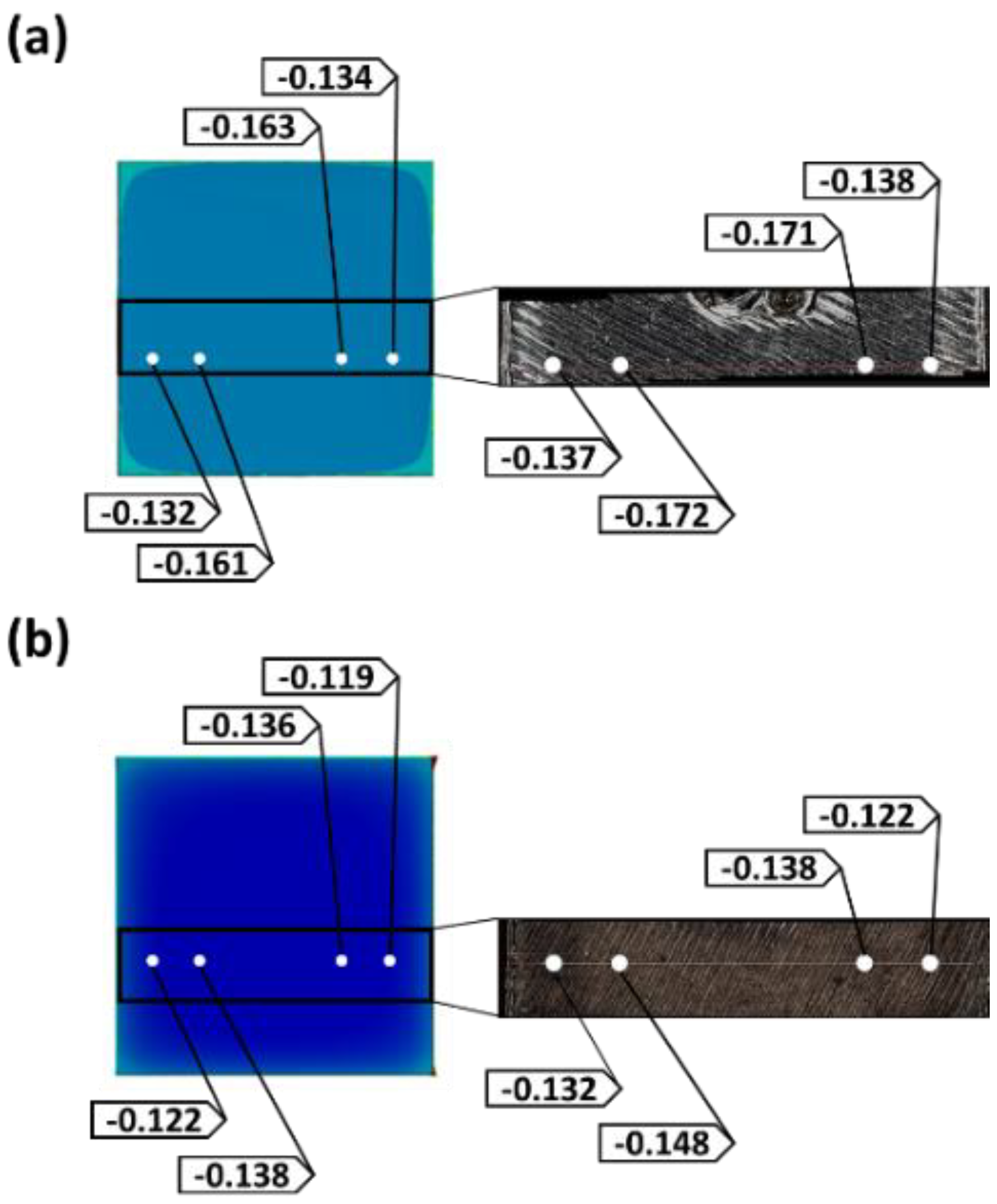
Figure 4.
Optical micrographs of the upper plate (YZ plane) of samples: (a) C2G-AB, displaying epitaxial grain growth across melt pool boundaries; and (b) C2G-HT, showing columnar grains formed after heat treatment with partially retained dendritic substructures.
Figure 4.
Optical micrographs of the upper plate (YZ plane) of samples: (a) C2G-AB, displaying epitaxial grain growth across melt pool boundaries; and (b) C2G-HT, showing columnar grains formed after heat treatment with partially retained dendritic substructures.
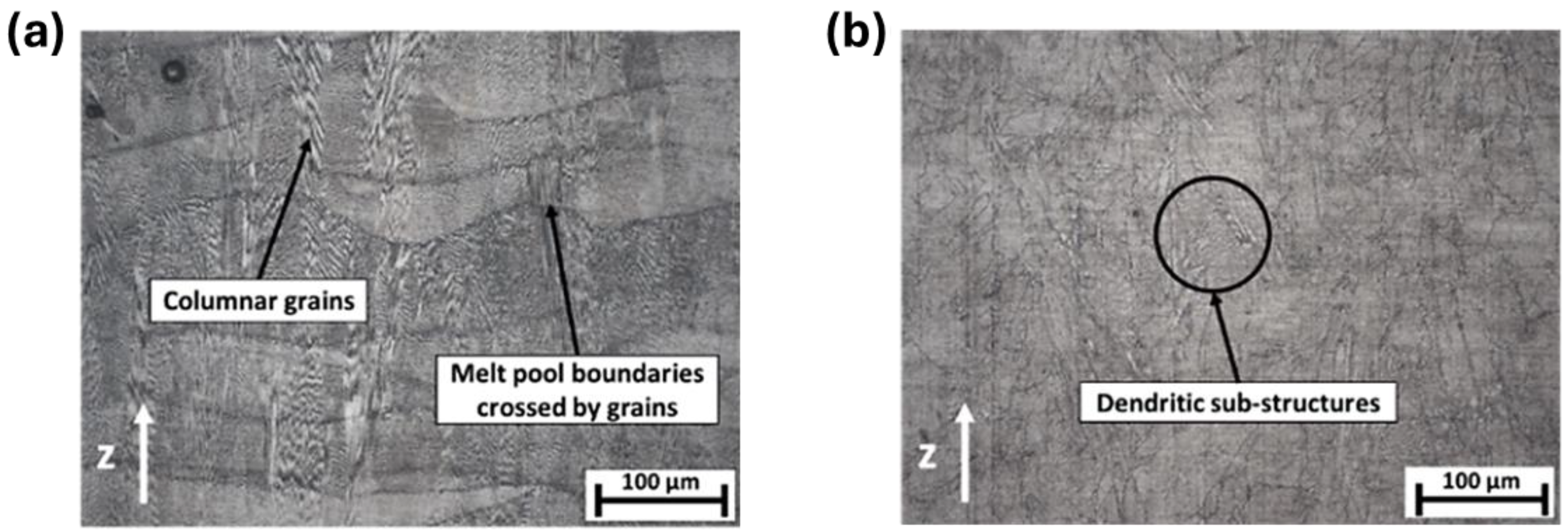
Figure 5.
Micrographs showing defects in terms of porosity observed along the YZ plane in a region of the lattice structure of the samples (a) C2F-AB and (b) C2G-AB.
Figure 5.
Micrographs showing defects in terms of porosity observed along the YZ plane in a region of the lattice structure of the samples (a) C2F-AB and (b) C2G-AB.
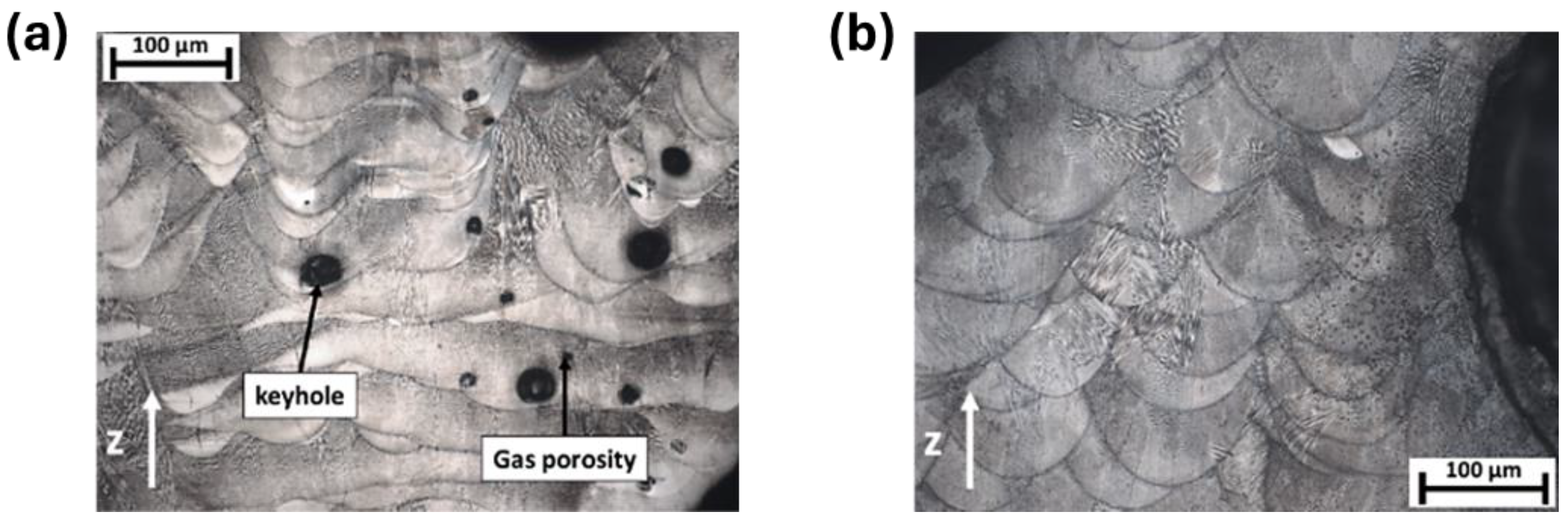
Figure 6.
Microstructures along the YZ plane of the lattice regions in (a) C2F-HT and (b) C2G-HT samples, showing heat-treatment-induced columnar grains with partially retained dendritic substructures.
Figure 6.
Microstructures along the YZ plane of the lattice regions in (a) C2F-HT and (b) C2G-HT samples, showing heat-treatment-induced columnar grains with partially retained dendritic substructures.
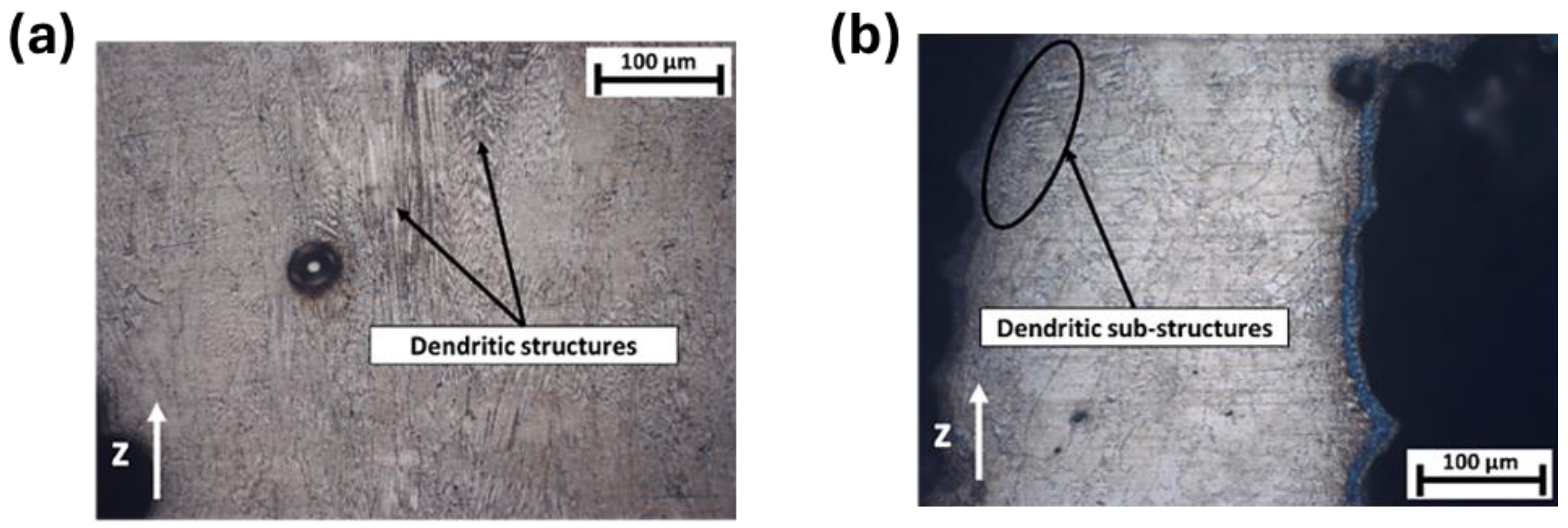
Figure 7.
(a) SEM image showing melt pools and the orientation of columnar dendritic substructures along the YZ plane; (b) TEM image of the C2G-AB sample along the YZ plane, highlighting the presence of Laves phases.
Figure 7.
(a) SEM image showing melt pools and the orientation of columnar dendritic substructures along the YZ plane; (b) TEM image of the C2G-AB sample along the YZ plane, highlighting the presence of Laves phases.
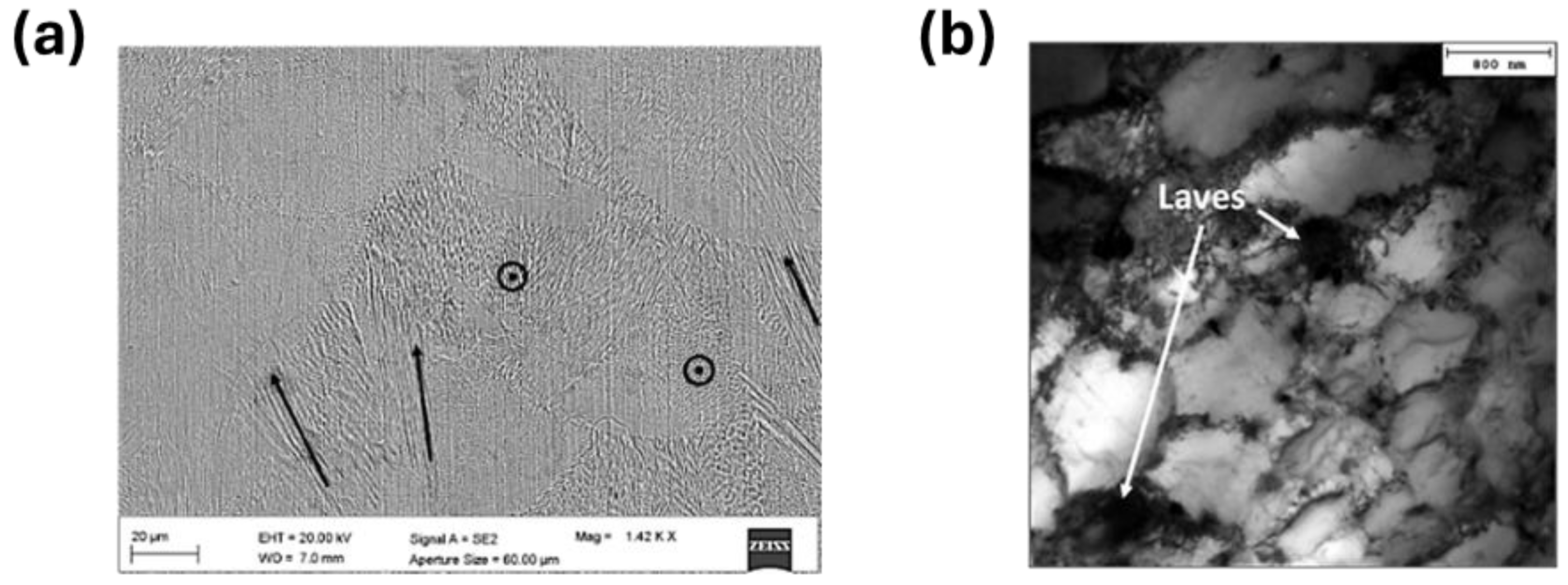
Figure 8.
(a) SEM images of the C2G-HT sample microstructure, highlighting the δ, γ’, and Laves precipitate phases; (b) Low-magnification TEM bright-field (BF) image of the C2G-HT sample along the YZ plane, showing the γ austenite cellular substructure and the precipitated needle-like δ and γ’ phases, as well as block-shaped Laves phases.
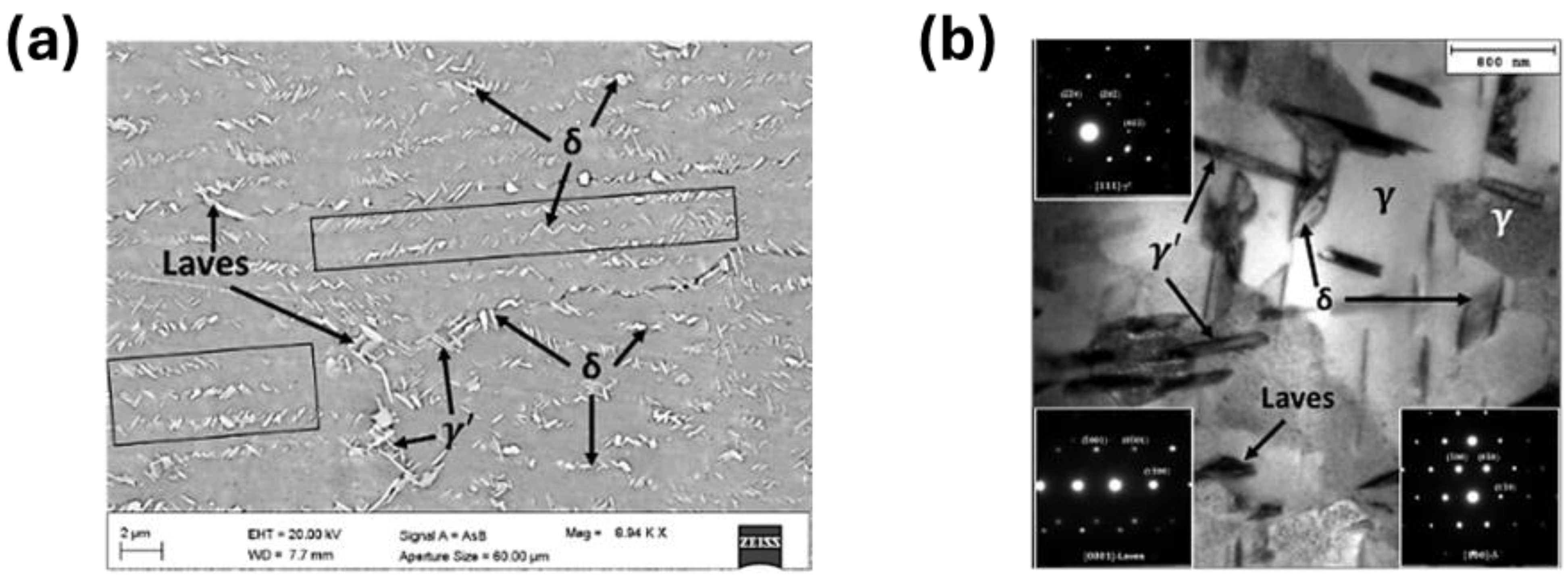
Figure 9.
Comparison of average microhardness values with standard deviations obtained along the YZ plane for (a) C2F-AB and C2F-HT samples, measured on the upper plate, lattice nodes, and struts, and (b) C2G-AB and C2G-HT samples, measured on the upper plate and on the lattice near the outer walls (left and right) and the central wall.
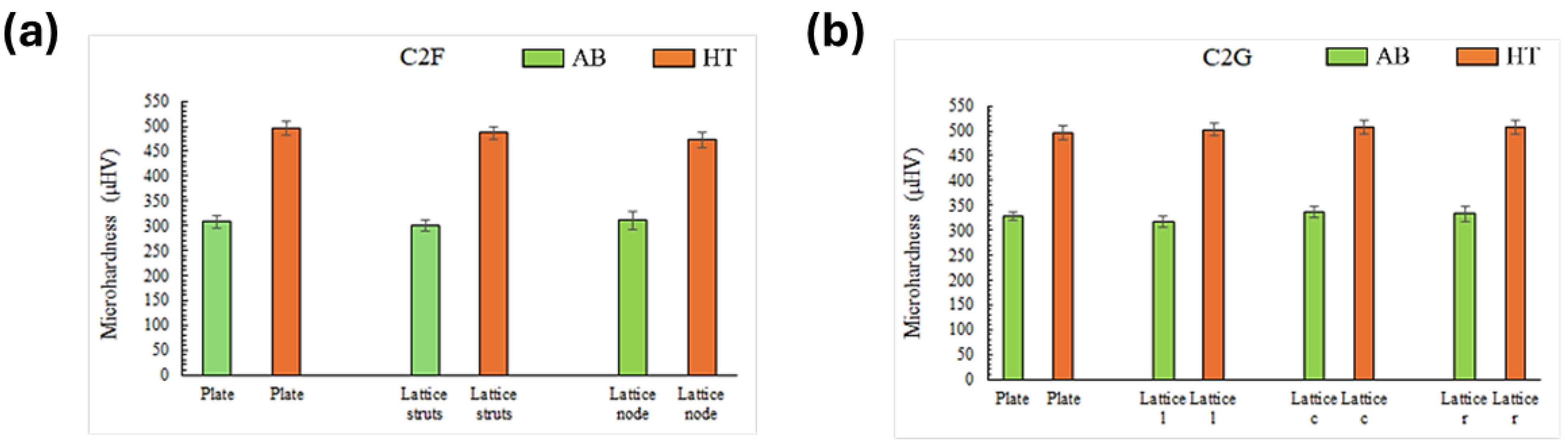

Table 1.
Lattice samples with variable unit cell topology (FCCZ and Gyroid) as a function of unit cell volume.
Table 1.
Lattice samples with variable unit cell topology (FCCZ and Gyroid) as a function of unit cell volume.
| Unit cell topology | Sample ID code | Cell size (mm) | Strut diameter (mm) |
| FCCZ | A2F | 2 | 0.3 |
| B2F | 2 | 0.4 | |
| C2F | 2 | 0.5 | |
| Gyroid | A2G | 2 | 0.3 |
| B2G | 2 | 0.4 | |
| C2G | 2 | 0.5 |
Table 2.
Setting of simulation parameters, corresponding to the EOS M290 DMLS default process parameters for processing Inconel 718 [15,16].
| Material | Inconel 718 |
| Layer thickness | 40 µm |
| Laser power | 285 W |
| Scanning speed | 960 mm/s |
| Hatch distance | 100 µm |
| Build plate preheating temperature | 80 °C |
| Powder temperature | 80 °C |
| Gas temperature | 22 °C |
| Layered tetrahedron size for lattice structures | 0.2 mm |
| Layered tetrahedron size for base plate | 4 mm |
Table 3.
Chemical composition (wt. %) of the Inconel 718 feedstock [17].
Table 3.
Chemical composition (wt. %) of the Inconel 718 feedstock [17].
| Fe | Ni | Cr | Nb | Mo | Ti | Al | Other |
| Balance | 50-55 | 17-21 | 4.75-5.50 | 2.80-3.30 | 0.65-1.15 | 0.20-0.80 | <1.0 |
Disclaimer/Publisher’s Note: The statements, opinions and data contained in all publications are solely those of the individual author(s) and contributor(s) and not of MDPI and/or the editor(s). MDPI and/or the editor(s) disclaim responsibility for any injury to people or property resulting from any ideas, methods, instructions or products referred to in the content. |
© 2025 by the authors. Licensee MDPI, Basel, Switzerland. This article is an open access article distributed under the terms and conditions of the Creative Commons Attribution (CC BY) license (http://creativecommons.org/licenses/by/4.0/).
Copyright: This open access article is published under a Creative Commons CC BY 4.0 license, which permit the free download, distribution, and reuse, provided that the author and preprint are cited in any reuse.


