
Submitted:
06 October 2025
Posted:
10 October 2025
You are already at the latest version
Abstract
Soft robotics focuses on the imitation of the work of living organisms and mostly utilizes soft deformable materials for actuation or object manipulation tasks. Soft robots or grippers can be used for tasks which are beyond the reach of conventional rigid body ones. Recently, soft flexible robotic grippers have attracted research and engineering interest. A variety of materials and actuation technologies incl. magnetorheological (MR) materials have been used for developing grippers for grasping and object manipulation purposes. The study provides an insight into a magnetorheological elastomer (MRE) based gripper that is capable of adapting to a variety of objects shapes. The authors reveal the gripper’s operating principle, the actuation mechanism, the gripper’s evaluation procedure and the results of a testing programme to examine the soft gripper’s operation with respect to its ability to adapt to objects of various shapes and sizes.
Keywords:
magnetorheological elastomer
; soft robotics
; gripper
1. Introduction
To begin with, robotic end-effectors provide robots with the capability to interact with the environment. They give robots particular functions without which they would be useless in any working environment. End-effectors are often referred to as End-Of-Arm-Tooling (EOAT). Various types of robotic end effectors include tools, magnets, clamps, grippers and the like. Grippers have given robots the abilities similar to human hands. In general, grippers are used in applications that require, e.g. lifting, touching, manipulating, grabbing, etc. Material handling, assembly, component transfer, loading, etc. can be managed by means of capable (pneumatic, mechanical, hydraulic, electrical, magnetic) robotic grippers. Therefore, a soft gripper whose actions are driven by applying an external stimuli of sufficient strength belongs to a category of specific EOATs. In comparison with conventional rigid body grippers, the soft grippers allow to reduce the robotic system’s complexity, minimize the risk of damaging the objects, allow to emulate the work of living organisms, are capable of accommodating a variety of shapes while maintaining the same or a similar level of control as the conventional EOATs [1,2].
A variety of smart material or conventional technologies can be used for the task, namely, smart memory alloys (SMAs) [3,4], pneumatics [5,6], electroactive elastomers (EAPs) [7,8], magnetorheological elastomers (MREs) [9,10] and magnetorheological fluids (MRFs) [11]. Often, several technologies can be employed to develop a hybrid gripper device. For instance, MREs and MRFs can be used in hybrid grippers, e.g., to adjust the friction force at the contact surface with the grasped object (MREs) [12] or to adapt the grip to the shape of the object (MRFs) [13].
Another approach to constructing soft grippers is the simultaneous use of multiple smart materials. This is advantageous in terms of simultaneously changing several parameters of these materials under the influence of a stimulus. An example of this approach is the simultaneous use of MRE and MRF in constructing a gripper [14,15]. Then, applying a magnetic field allows for simultaneous influence on both MRE and MRF, providing additional benefits.
So far, the use of MR materials in soft robotics has not been researched to the same extent as their electric (electroactive) counterparts. However, more studies involving MR/MRE prototypes have emerged over the years [16,17].
Briefly, the MRFs are suspensions of micron-sized soft magnetic particles in a non-conductive carrier oil. For comparison, MREs feature a soft polymer matrix with embedded micron-sized Fe particles. It is their ability to subject to the external (magnetic) stimuli that links the two material technologies. Historically, MRFs have been mostly used in vibration damping applications as in semi-active vehicle chassis systems [18] or high-quality optical finishing [19]. At the same time, no commercial application of MREs has been proven to the same extent as the MRF-based vibration control systems for passenger vehicles.
While the smart fluids have found their use in the semi-active automotive suspension systems [18], for example, their solid counterparts have not been commercialized to the same extent. However, they have been researched in various application areas, e.g. vibration control applications [20] or soft robotics [21]. Both MR material types are capable of changing their physical properties under the influence of external magnetic fields [22].
In general, soft grippers that rely on the MR materials can be split into three categories based on their operating principles: 1 – magnetic field based modulation of the material’s storage and/or loss modulus, 2 – magnetic field derived deformation, 3 – adhesive force change [21,23]. The most well-known controllable ability of MRE is the ability to vary storage modulus under the influence of magnetic field [24]. Moreover, the material is known to deform in the presence of magnetic fields. As such, the material can be implemented in mechanical structures in which the property change will lead to imbalance and movement until the moment when the structure again enters a state of equilibrium. Two known examples can be the two-link manipulator [25] or the soft MRE gripper [26] bending/unbending under the influence of magnetic field.
Utilizing the controllable property change of MRE materials can facilitate the design of a soft gripper. Enhancing the magnetic field can lead to either an increase [27] or a decrease [28] in the grip force. Both approaches have their advantages. With the former it is possible to provide a stronger grip, whereas the latter approach provides a grip in the absence of a magnetic field. The study highlighted in this paper reveals a concept of an MRE based gripper with a component deformable upon the magnetic field application.
Briefly, the study is organized as follows. Section 1 contains the introductory background material. Next, Section 2 highlights the soft gripper’s operating principle and dimensions. Moreover, Section 3 includes the description of the rig developed for testing the gripper, and Section 4 reveals the obtained results throughout the course of the experiments. Finally, Section 5 contains a summary of the study as well as a discussion.
2. MRE Gripper
The MRE gripper’s CAD model is illustrated in Figure 1a. The concept incorporates the solenoid (4), upper housing (2), lower housing (5) and the elastic and deformable MRE cover (1). As the elastic cover is made of the MRE material sample, its shape is subject to changes while in the presence of magnetic field induced by the current in the solenoid. The coil (3) is wound around the solenoid core. The MRE material is isotropic. The material was manufactured in-house by the authors. A CIP carbonyl iron powder with the average particle size of 5 was the key ingredient, and the base silicon material was EcoFlex 00-10; the digits in the base material’s name denote its Shore hardness level. The CIP particles were thoroughly mixed, poured into a 3D-printed PLA mould, and then seasoned.
As shown in Figure 1b the cover was cast into a circular flexible shape with the regular hexagonal aperture in the center. The cover’s material is ferromagnetic. It is, therefore, expected to be attracted towards the solenoid’s core surface while it is being powered by the resulting force. The attraction of the material towards the core causes the aperture to close. The illustration shows diagonals of a circle circumscribed about the hexagon , , (gripper’s diagonals). When fully open, the hexagonal aperture dimensions are: mm, mm, mm. The differences are due to the imperfections of the cast mould. That translates into the off-state (no magnetic field applied) aperture area equal to
Supplying the current to the coil results in inducing the magnetic flux in the solenoid’s structure. The resulting force pulls or attracts the deformable cover towards the solenoid’s core, thus closing the aperture. The solenoid dimensions are as follows: outer diameter – 100 mm, coil window outer diameter – 84 mm, coil window inner diameter – 46 mm, core outer diameter – 46 mm, height – 40 mm, MRE cover height – 25 mm.
3. Experimental Setup
The experiments were carried out with the simple setup shown in Figure 2. It involved the MRE gripper positioned on a table with the camera facing down and on a tripod. As shown, a DC programmable power supply (PCS) was used for powering the solenoid’s coil. The current was measured using the FLUKE i30 current probe. The probe signal was sent to the analog input of an Advantech USB-4716 USB I/O DAC module. The changes in the induced magnetic flux density in the electromagnet circuit (as induced by the coil current changes) were recorded using the BELL-5180 magnetometer (not shown) and stored in a PC workstation’s mass memory via the Advantech I/O module. Throughout the measurements, the flux probe was located between the MRE cover and the plastic surface on the core. The transverse probe was used for measuring the flux density above the core (). Determining the optimum location of the probe was based on 2D-axisymmetric magnetostatic finite-element model simulations and using the B-H MRE material curves obtained by means of the measurements with the vibrating sample magnetometer LakeShore VSM 8600.
The behavior of the gripper (tracking of the hexagonal aperture area variation with time) by means of the magnetic field induced was recorded by the camera simultaneously with the prescribed current excitation. That enabled a quantitative assessment of the gripper’s operation in a contactless and non-invasive manner.
Briefly, the solenoid was excited by applying a periodic current waveform to the coil terminals. Exemplary time histories of the measured triangular coil current and the flux density are highlighted in Figure 3. The authors carried out preliminary measurements of the two quantities to examine the relationship between the current and the flux density. The cycle time of the input signal was 50 s, and its amplitude was 3 A.
Note that the current variation from 0 to 3 A results in a linear relationship between the current and the flux density. The plot shown in Figure 4 shows no signs of magnetic saturation. The hysteresis width around 0 A is negligibly small. Therefore, it was assumed that the magnetic density–coil current relationship is linear, and it can be expressed quantitatively by means of the simple gain mT/A. Therefore, in all the subsequent measurements, only the coil current was measured directly, and the flux density was calculated by multiplying the measured current values by the flux density gain k.
The testing programme was split into two series. With the first one, the MRE concept was tested without any objects simply to assess its free-state operation and to test the developed contactless method for assessing the aperture area variation with time. The second test series involved gripping objects of different shapes and dimensions, i.e. cylinders and cubes.
4. Results
The experimental results are presented in the sections that follow below.
4.1. Free (No Load) State
The first series of the experiments involved handling the gripper with no objects (free-state). Figure 5 highlights the aperture when fully opened (a) and fully closed (b), respectively. The illustration shows 6 red markers at the corners of the hexagonal aperture. The current locations of the markers are extracted from computer vision (video) data for the purpose of calculating the aperture area.
The location of the red markers varies while in operation. The diagonals () are plotted between the opposite vertices (markers). The length of each diagonal can be measured (see Figure 6a). The diagonal lengths will differ slightly due to minor discrepancies in the shape of the aperture or deviations from the ideal hexagonal shape. In the absence of magnetic field, the diagonal lengths are 56, 56, and 58 mm, respectively. Clearly, the length of each diagonal will vary with the magnetic field applied as the MRE cover gets attracted towards the core.
To extract the marker coordinates, the Image Processing Toolbox module of the MATLAB computing environment was used in real-time. That allowed for the detection and the acquisition of the coordinates of the 6 markers (see Figure 6b) by means of the Blob Analysis framework. The framework can be used for the detection and analysis of the pixels , () corresponding to the registered markers (see Figure 6c). The marker coordinates are expressed as pixel coordinates of the original image frame. It is, therefore, necessary to scale them to generally accepted system of measures/units. Based on the acquired marker coordinates and the scale coefficient , it is possible to calculate the diagonals , , according to the formula:
where w, j - indices of the opposite markers. By tracking the length of each diagonal, it is then possible to assess the gripper’s performance while operating. An elegant alternative is the assessment of the gripper’s performance using the calculated aperture area in real-time. To accomplish this goal, a procedure for calculating the aperture area (the hexagonal shape illustrated in Figure 6d)) based on the image coordinates , can be devised as follows:
Variations of the diagonals , , when subjected to magnetic field (current) excitations are shown in Figure 7. The highlighted behaviour corresponds to the triangular waveform presented in Figure 3. As illustrated, increasing the current level results in the reduction of the diagonals’ length. It is also worth noting that the diagonals are not equal – the gripper is not completely axially symmetrical.
Observations of the data in Figure 7 imply that the assessment of the gripper’s performance based on the diagonals is not sufficient. This can be accomplished by evaluating and tracking the aperture area during the operation of the gripper, as highlighted in Figure 13. The aperture area is reduced by a factor of 4, and it is repeatable without any visible degradation of its performance.
Figure 8.
Time history of the recorded aperture area
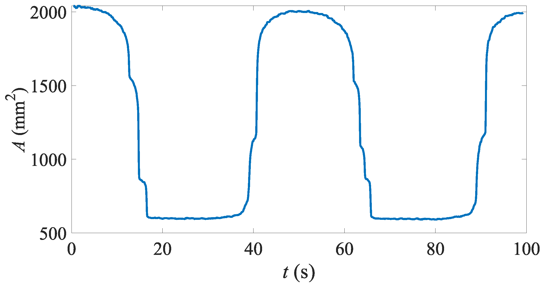
The time history in Figure 9 shows a visible hysteresis in positive/negative current change directions or when closing and opening the gripper. It is evident that the opening/closing current levels are indeed distinct. In the presented example the closing current is equal to 2.2 A, and the opening current 1 A. It implies that in order to close the gripper it is necessary to apply the current to the coil of 2.2 A. For comparison, maintaining it in the closed condition requires the current lower than 2.2 A but higher than 1 A.
Next, a series of transient tests was performed to examine the behaviour of the gripper when subjected to current step inputs. The time history of the acquired aperture area is highlighted in Figure 10. As observed, the step waveform was designed in such a way to result in a series of pulses of increasing amplitude.
Based on the analysis of the obtained data, it is evident that that gripper starts closing at the current level of appr. 2 A. The response time T was then estimated as follows
where – aperture area when fully opened, – aperture area change, T – time constant. The results are summarized in Table 1. A delay of 0.25 s should be accounted for. At the current level of 1 A (first pulse) there was no reaction of the gripper. Increasing the current input amplitude up to 2 A (second pulse) results in a slow closing action of the aperture as manifested by the time constant T. Subsequent pulses of larger amplitudes had a positive effect on the response time, i.e. it was significantly reduced. Minor inflation of the time constant at the two largest current levels is likely due to aperture area estimation errors. To summarize, on-off and off-on response times are distinct.
4.2. Cylindrical Objects
This section reveals the results of the experiment series involving the handling of cylindrical objects. The tested objects were 4 3D printed cylinders of equal height and different diameters: (as shown in Figure 11). As in the previous section, the gripper’s performance was evaluated based on the observations of the aperture area A.
The tests involving the cylinders were carried out using the current input waveform as already described. The results are presented in Figure 12 as plots of the aperture area vs the exciting current. It can be seen that the aperture area in the closed state (grip) depends on the size of the grasped object.
With the largest cylinder ( mm), the current at which the object is fully captured (closing current) is equal to appr. 2.8 A. As the object diameter decreases, the current gradually decreases to appr. 2.2 A for the smallest object ( mm). The opening current (at which the objects were released) was equal to 1 A regardless the cylinder size.
4.3. Cubic Objects
The second series of the experiments involving objects concerned cubes. As in the above-mentioned scenario, the authors used 4 3D-printed cubes; the diagonals of the cubes were: mm (see. Figure 13).
Similarly, the solenoid’s current excitation was a periodic triangular waveform of the amplitude equal to 3 A. The waveform’s cycle time was 50 s. The results are presented in Figure 14 for the respective objects. Again, it can be observed that closing/opening current levels vary with the tested cube size. The observation coincides with the results obtained above.
The results showed that the closing current decreases with decreasing diameter of the object being grasped.
Similarly to the case of cylindrical objects, it was observed that the closing current decreases with decreasing diameter of the object. In the case of the largest cube the closing current is equal to 2.6 A and 2.3 A for the smaller one ( mm), respectively. The smallest cube ( mm) could not be grasped. The opening current is approximately equal to 1 A regardless of the cube size.
5. Summary
To summarize, the main goal of the presented research was to investigate the feasibility of a simple MRE soft deformable gripper that could be used to perform tasks involving the manipulation of objects of various shapes and dimensions. The authors describe the concept of the soft gripper based on the magnetic field controlled MRE materials, its operating principle, the test setup, and the obtained results. A computer vision based (contactless) method was developed for quantitatively verifying the device’s performance by measuring changes in the gripper’s aperture area over time. The core purpose of the research conducted by the authors was intended to verify the developed concept’s operation and to examine its basic functionality. Load capacity tests were beyond the scope of this research.
The tests involved handling of cylindrical and cubic objects, respectively, of various sizes. Based on the analysis of the test results, it is apparent that the gripper’s operation is consistent. Observations of the aperture area time histories via the contactless method suggest that its operation is repeatable, with no visible degradation of the flexible casing (at least during the tests conducted by the authors). Furthermore, the test results allowed the authors to determine the gripper’s closing and minimum holding currents, respectively. It is also worth noting that the (contactless) method for measuring the aperture area based on computer vision data can be used in the gripper’s planned control system.
Author Contributions
Conceptualization, D.G. and J.G.; methodology, D.G.; software, D.G.; validation, D.G., J.G. and B.S.; formal analysis, D.G.; investigation, D.G.; resources, D.G and J.G.; data curation, D.G.; writing—original draft preparation, D.G, J.G, B.S and P.O; writing—review and editing, D.G, J.G, B.S and P.O. All authors have read and agreed to the published version of the manuscript.
Funding
This research received no external funding.
Data Availability Statement
The data generated during the experiments can be made available upon request.
Conflicts of Interest
The authors declare no conflicts of interest.
References
- Rus, D.; Tolley, M.T. Design, fabrication and control of soft robots. Nature 2015, 521, 467–475. [Google Scholar] [CrossRef]
- Zaidi, S.; Maselli, M.; Laschi, C.; Cianchetti, M. Actuation Technologies for Soft Robot Grippers and Manipulators: A Review. Current Robotics Reports 2021, 2, 355–369. [Google Scholar] [CrossRef]
- Lee, J.H.; Chung, Y.S.; Rodrigue, H. Long Shape Memory Alloy Tendon-based Soft Robotic Actuators and Implementation as a Soft Gripper. Scientific Reports 2019, 9, 11251. [Google Scholar] [CrossRef] [PubMed]
- Rodrigue, H.; Wang, W.; Kim, D.R.; Ahn, S.H. Curved shape memory alloy-based soft actuators and application to soft gripper. Composite Structures 2017, 176, 398–406. [Google Scholar] [CrossRef]
- Ye, Y.; Cheng, P.; Yan, B.; Lu, Y.; Wu, C. Design of a Novel Soft Pneumatic Gripper with Variable Gripping Size and Mode. Journal of Intelligent and Robotic Systems: Theory and Applications 2022, 106, 1–15. [Google Scholar] [CrossRef]
- Kim, D.; Baek, S.R.; Kim, M.S.; Park, C.Y.; Lee, I.H. Design and manufacturing process of pneumatic soft gripper for additive manufacturing. Sensors and Actuators A: Physical 2024, 370, 115218. [Google Scholar] [CrossRef]
- Dou, X.; Chen, Z.; Ren, F.; He, L.; Chen, J.; Yin, L.J.; Luo, Y.; Dang, Z.M.; Mao, J. Dielectric Elastomer Network with Large Side Groups Achieves Large Electroactive Deformation for Soft Robotic Grippers. Advanced Functional Materials 2024, 34, 1–9. [Google Scholar] [CrossRef]
- Pourazadi, S.; Bui, H.; Menon, C. Investigation on a soft grasping gripper based on dielectric elastomer actuators. Smart Materials and Structures 2019, 28, 035009. [Google Scholar] [CrossRef]
- Bernat, J.; Czopek, P.; Superczynska, P.; Gajewski, P.; Marcinkowska, A. The Construction of a Soft Gripper Based on Magnetorheological Elastomer with Permanent Magnet. arXiv preprint arXiv:2407.13477 2024.
- Li, X.; Zhang, Z.; Sun, M.; Wu, H.; Zhou, Y.; Wu, H.; Jiang, S. A magneto-active soft gripper with adaptive and controllable motion. Smart Materials and Structures 2021, 30, 015024. [Google Scholar] [CrossRef]
- Koivikko, A.; Drotlef, D.M.; Sitti, M.; Sariola, V. Magnetically switchable soft suction grippers. Extreme Mechanics Letters 2021, 44, 101263. [Google Scholar] [CrossRef]
- Park, J.E.; Shin, H.N.; Park, J.; Suh, J.; Kim, Y.K. Friction variable rubber pad using magnetorheological elastomer for robot grippers. Journal of Intelligent Material Systems and Structures 2023, 34, 292–302. [Google Scholar] [CrossRef]
- Białek, M.; Jędryczka, C.; Milecki, A. Investigation of Thermoplastic Polyurethane Finger Cushion with Magnetorheological Fluid for Soft-Rigid Gripper. Energies 2021, 14, 6541. [Google Scholar] [CrossRef]
- Choi, Y.T.; Hartzell, C.M.; Leps, T.; Wereley, N.M. Gripping characteristics of an electromagnetically activated magnetorheological fluid-based gripper. AIP Advances 2018, 8. [Google Scholar] [CrossRef]
- Hartzell, C.M.; Choi, Y.T.; Wereley, N.M.; Leps, T.J. Performance of a magnetorheological fluid-based robotic end effector. Smart Materials and Structures 2019, 28, 035030. [Google Scholar] [CrossRef]
- Li, Y.; Li, J.; Li, W.; Du, H. A state-of-the-art review on magnetorheological elastomer devices. Smart Materials and Structures 2014, 23, 123001. [Google Scholar] [CrossRef]
- Kumar, J.S.; Paul, P.S.; Raghunathan, G.; Alex, D.G. A review of challenges and solutions in the preparation and use of magnetorheological fluids. International Journal of Mechanical and Materials Engineering 2019, 14, 13. [Google Scholar] [CrossRef]
- Wang, Z.; Liu, C.; Zheng, X.; Zhao, L.; Qiu, Y. Advancements in Semi-Active Automotive Suspension Systems with Magnetorheological Dampers: A Review. Applied Sciences 2024, 14. [Google Scholar] [CrossRef]
- Kordonski, W.I.; Jacobs, S.D. Magnetorheological finishing. International Journal of modern physics B 1996, 10, 2837–2848. [Google Scholar] [CrossRef]
- Deng, Z.; Dapino, M.J. Review of magnetostrictive materials for structural vibration control. Smart Materials and Structures 2018, 27, 113001. [Google Scholar] [CrossRef]
- Cramer, J.; Cramer, M.; Demeester, E.; Kellens, K. Exploring the potential of magnetorheology in robotic grippers. Procedia CIRP 2018, 76, 127–132. [Google Scholar] [CrossRef]
- Ahamed, R.; Choi, S.B.; Ferdaus, M.M. A state of art on magneto-rheological materials and their potential applications. Journal of Intelligent Material Systems and Structures 2018, 29, 2051–2095. [Google Scholar] [CrossRef]
- Xu, M.; Liu, Y.; Li, J.; Xu, F.; Huang, X.; Yue, X. Review of Flexible Robotic Grippers, with a Focus on Grippers Based on Magnetorheological Materials, 2024. [CrossRef]
- Gutenko, D.; Orkisz, P.; Sapiński, B. Laboratory Testing and Modelling of Magnetorheological Elastomers in Tension Mode. Acta Mechanica et Automatica 2024, 18, 291–299. [Google Scholar] [CrossRef]
- Gutenko, D. Concept of a soft gripper based on a magnetoactive polymer: Static calculations. In Proceedings of the 2020 21st International Conference on Research and Education in Mechatronics (REM), 2020, pp. 1–5. [CrossRef]
- Ding, W.; Zhou, Y.; Sun, M.; Fu, H.; Chen, Y.; Zhang, Z.; Pei, Z.; Chai, H. Magnetorheological elastomer actuated multi-stable gripper reinforced stiffness with twisted and coiled polymer. Thin-Walled Structures 2023, 193, 111223. [Google Scholar] [CrossRef]
- Guan, R.; Zheng, H.; Liu, Q.; Ou, K.; sen Li, D.; Fan, J.; Fu, Q.; Sun, Y. DIW 3D printing of hybrid magnetorheological materials for application in soft robotic grippers. Composites Science and Technology 2022, 223, 109409. [Google Scholar] [CrossRef]
- Bernat, J.; Gajewski, P.; Kapela, R.; Marcinkowska, A.; Superczyńska, P. Design, Fabrication and Analysis of Magnetorheological Soft Gripper. Sensors 2022, 22, 2757. [Google Scholar] [CrossRef] [PubMed]
Figure 1.
Soft MRE gripper concept: a) CAD model, b) base dimensions
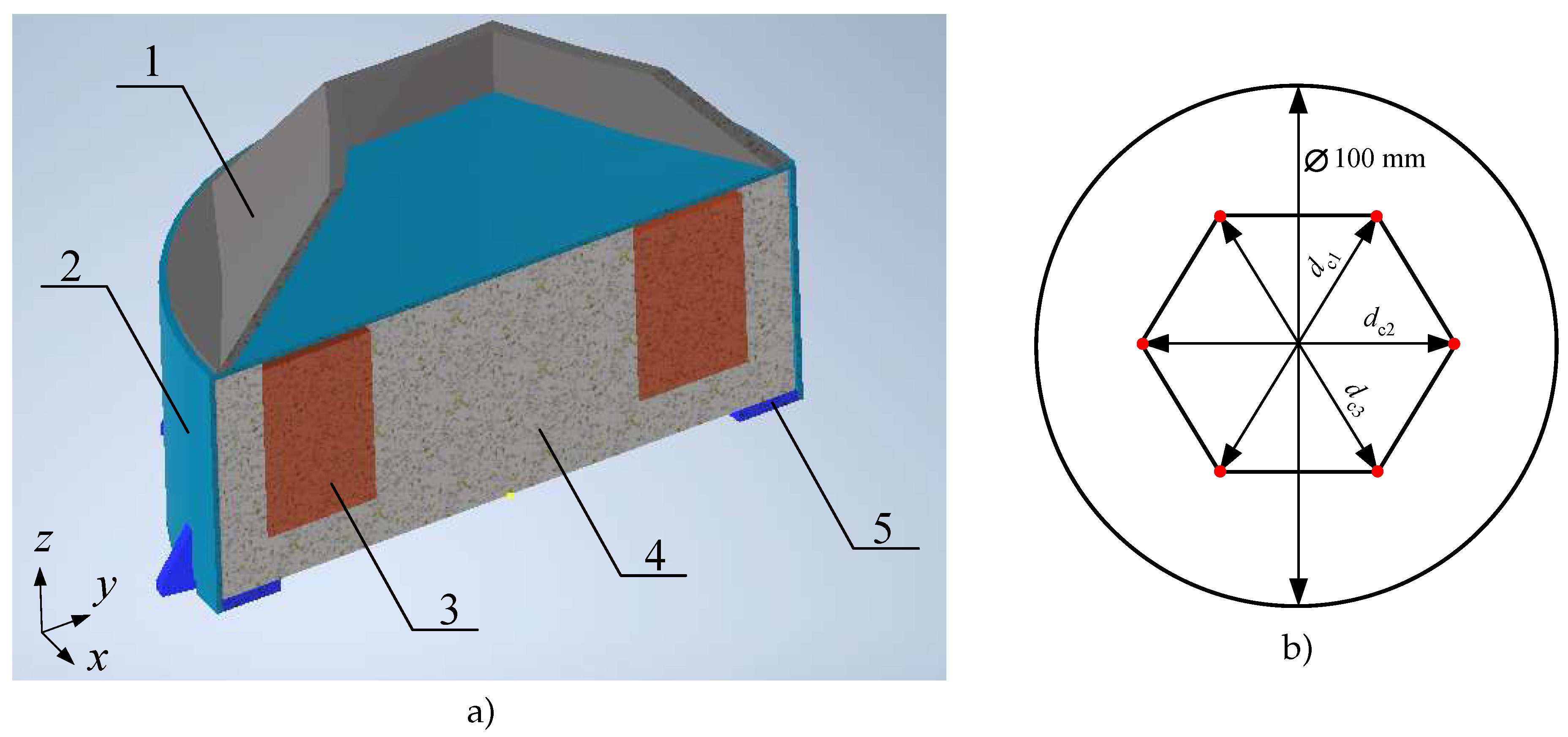
Figure 2.
Test fixture and data processing diagram
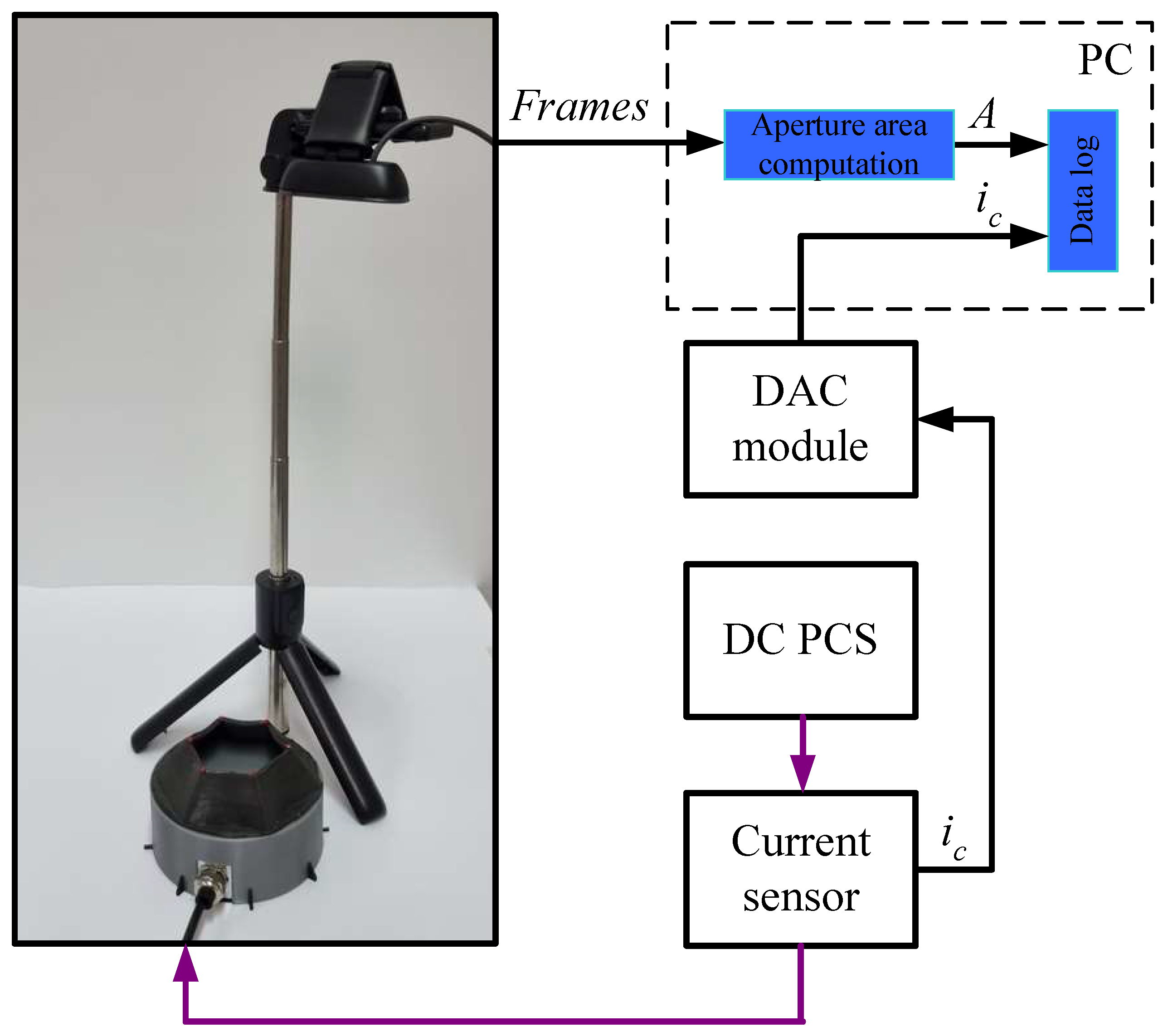
Figure 3.
Exemplary time histories of the test coil current and the flux density
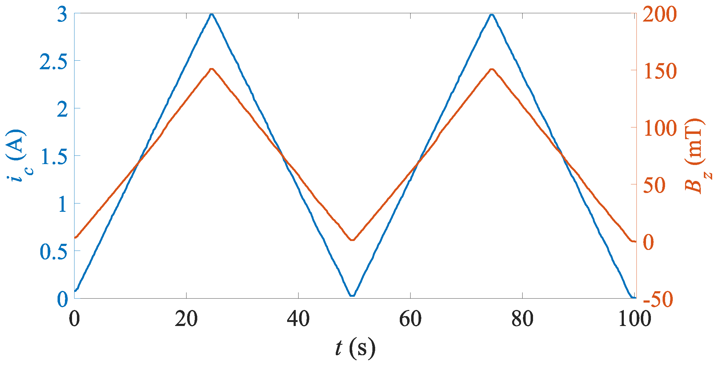
Figure 4.
Flux density vs input coil current:
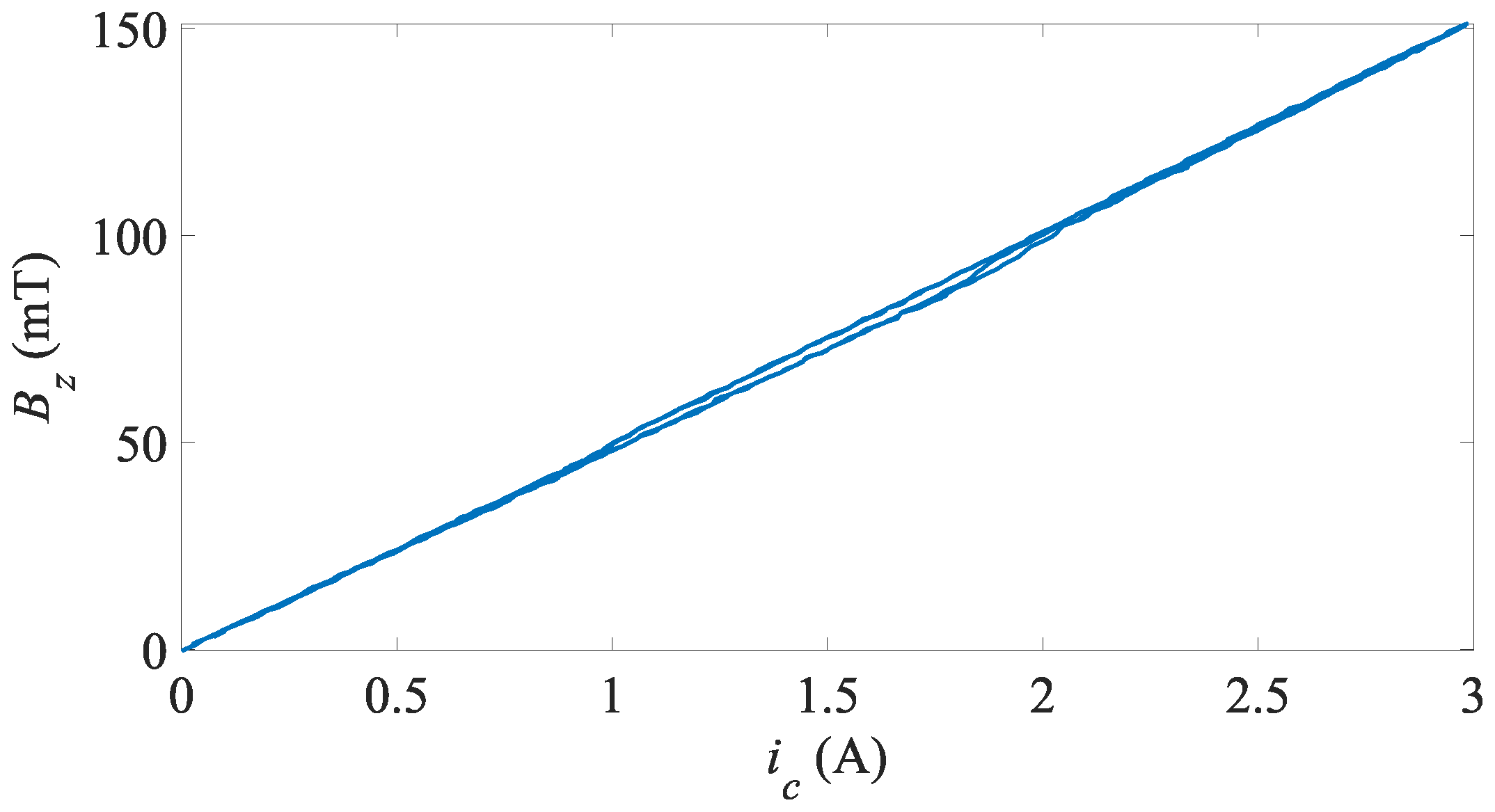
Figure 5.
MRE grippe’s aperture: a) opened, b) closed
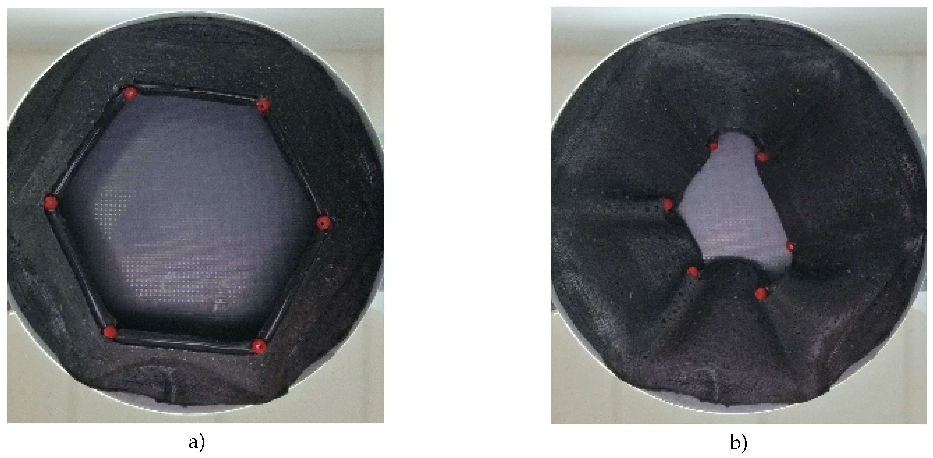
Figure 6.
Acquisition of the aperture area: a) detection of the diagonals, b) marker positions, c) locations of the markers, d) hexagon (aperture) imaging
Figure 6.
Acquisition of the aperture area: a) detection of the diagonals, b) marker positions, c) locations of the markers, d) hexagon (aperture) imaging
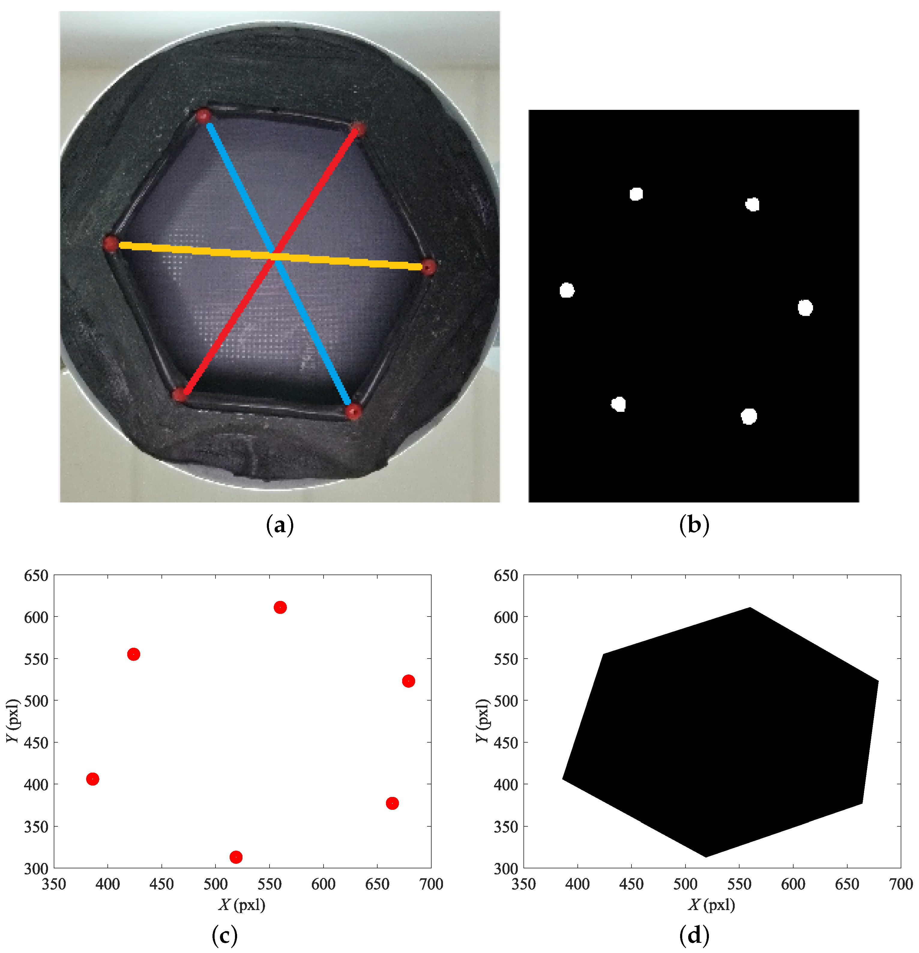
Figure 7.
Variation the diagonals with time
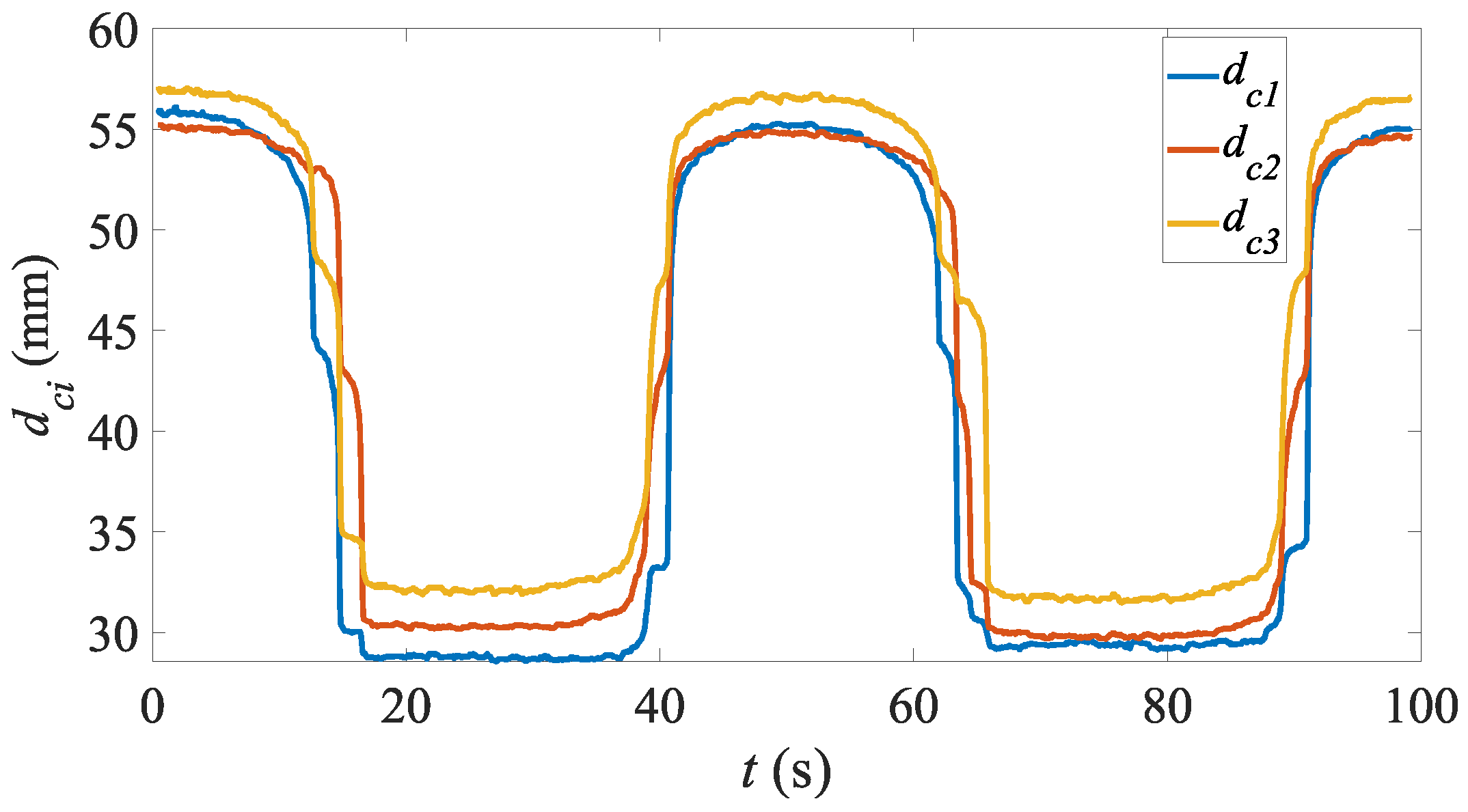
Figure 9.
Aperture area variation vs coil current:
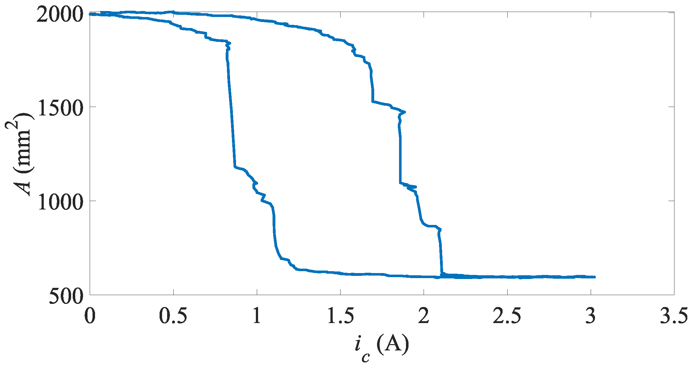
Figure 10.
Aperture area vs time – step input
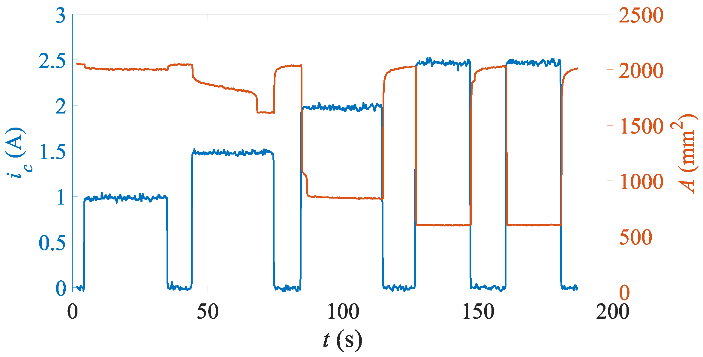
Figure 11.
Handling of cylindrical objects: a) mm – fully opened, b) mm – fully closed, c) mm – fully opened, d) mm – fully closed, e) mm – fully opened, f) mm – fully closed, g) mm – fully opened, h) mm – fully closed
Figure 11.
Handling of cylindrical objects: a) mm – fully opened, b) mm – fully closed, c) mm – fully opened, d) mm – fully closed, e) mm – fully opened, f) mm – fully closed, g) mm – fully opened, h) mm – fully closed
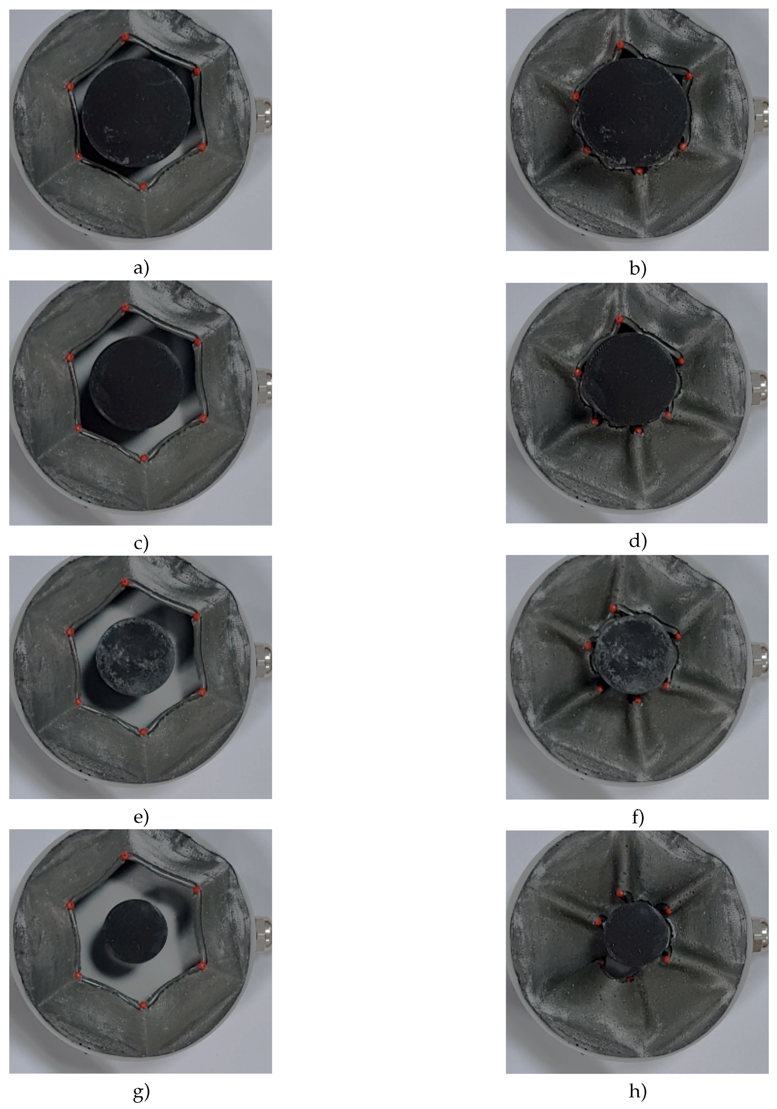
Figure 12.
Cylindrical objects: aperture area vs coil current –
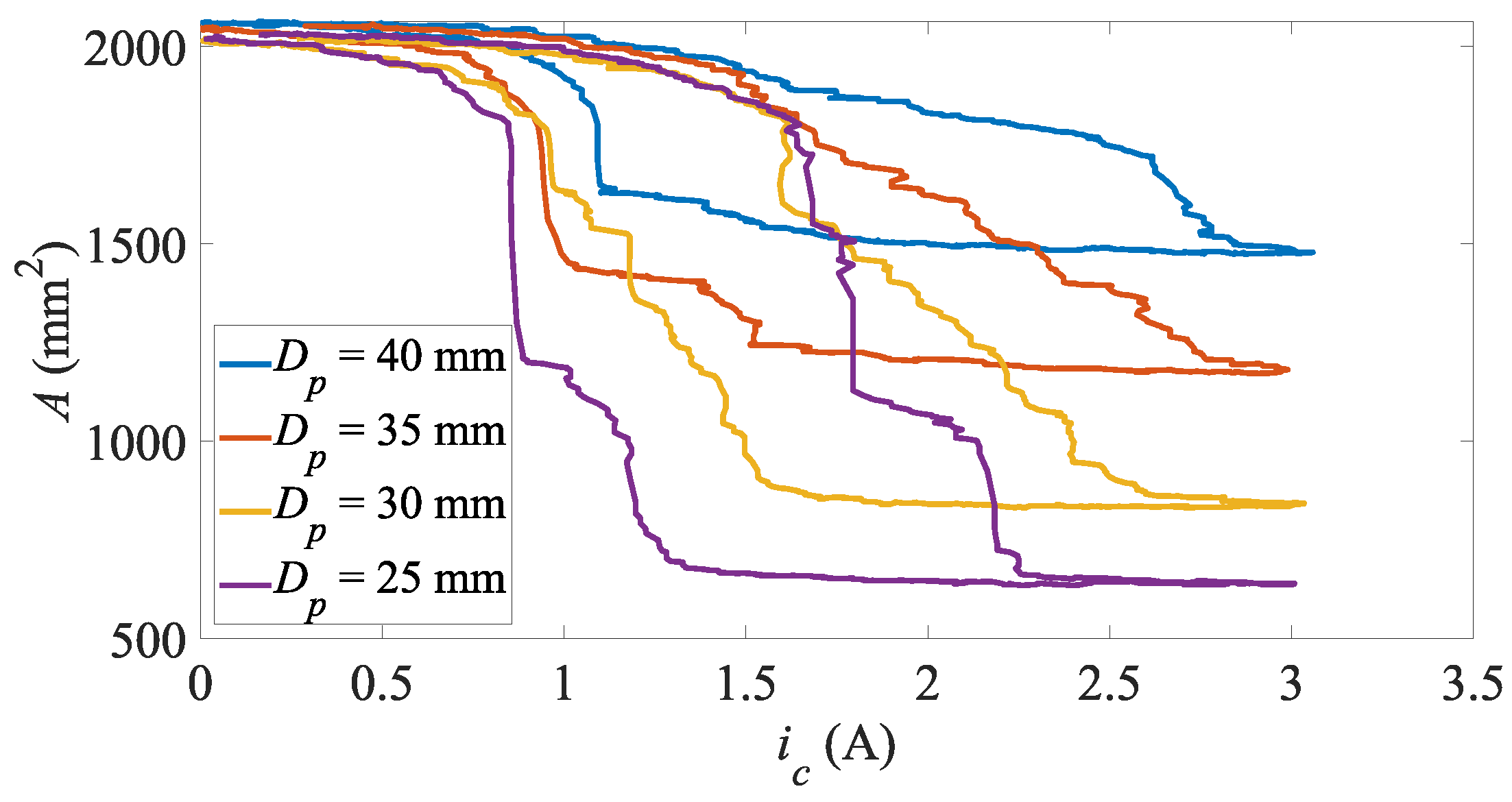
Figure 13.
Handling of cubic objects: a) mm – fully opened, b) mm – fully closed, c) mm – fully opened, d) mm – fully closed, e) mm – fully opened, f) mm – fully closed, g) mm – fully opened, h) mm – fully closed
Figure 13.
Handling of cubic objects: a) mm – fully opened, b) mm – fully closed, c) mm – fully opened, d) mm – fully closed, e) mm – fully opened, f) mm – fully closed, g) mm – fully opened, h) mm – fully closed
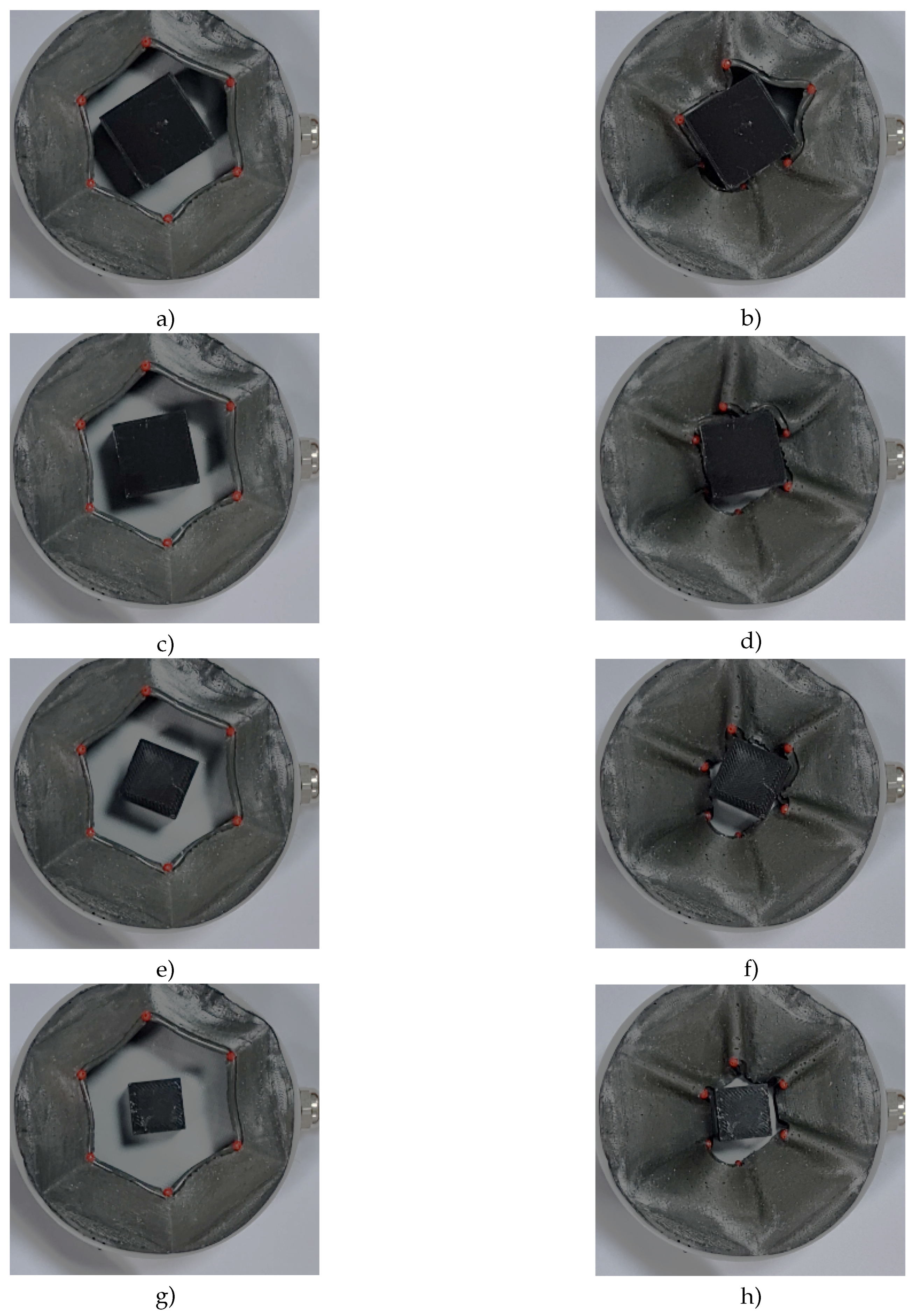
Figure 14.
Cubic objects: aperture area vs coil current –
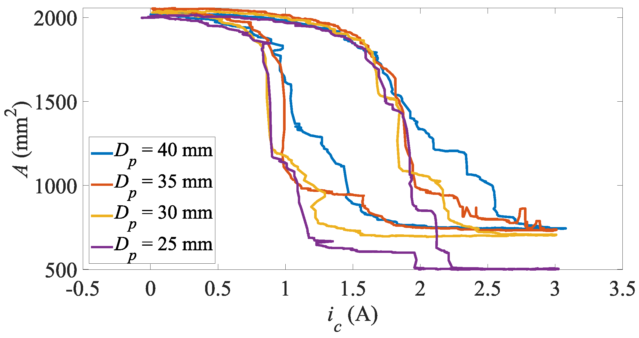

Table 1.
Estimated response times T – step excitation; – coil current pulse amplitude
| , | , | T, s | |
|---|---|---|---|
| A | 2060 | 56 | 2.106 |
| A | 2046 | -51 | 0.469 |
| A | 1963 | 150 | 5.975 |
| A | 2028 | -444 | 0.183 |
| A | 1981 | 1129 | 0.456 |
| A | 2006 | -1310 | 0.212 |
| A | 2037 | 1436 | 0.0105 |
| A | 2011 | -1519 | 0.147 |
| A | 2079 | 1475 | 0.0157 |
| A | 2041 | -1623 | 0.191 |
Disclaimer/Publisher’s Note: The statements, opinions and data contained in all publications are solely those of the individual author(s) and contributor(s) and not of MDPI and/or the editor(s). MDPI and/or the editor(s) disclaim responsibility for any injury to people or property resulting from any ideas, methods, instructions or products referred to in the content. |
© 2025 by the authors. Licensee MDPI, Basel, Switzerland. This article is an open access article distributed under the terms and conditions of the Creative Commons Attribution (CC BY) license (http://creativecommons.org/licenses/by/4.0/).
Copyright: This open access article is published under a Creative Commons CC BY 4.0 license, which permit the free download, distribution, and reuse, provided that the author and preprint are cited in any reuse.


