Submitted:
06 May 2023
Posted:
08 May 2023
You are already at the latest version
Abstract
Conducting related research is crucial since there are still many problems that need to be resolved in the research on soft robots in the areas of material selection, structure design and manufacture, and drive control. Soft manipulators, a subset of soft robots, are now a popular area of study for many researchers. In comparison to typical manipulators, soft manipulators feature a high degree of gripping flexibility and a basic morphological structure. They are composed of flexible materials. It has a wide range of potential applications in healthcare, rehabilitation, bionics, and detection, and it can compensate for the drawbacks of rigid manipulators in some use scenarios. A modular soft-body torsional gripping system is developed after a torsional and gripping actuator is conceived, constructed, and its performance is examined. The torsion actuator and the grasping actuator can be combined in the system in a modular fashion. With the help of RGB-D vision algorithms, this multi-modular setup makes it possible to combine soft actuators with various twisting degrees and achieve exact gripping. Through pneumatic control, the target object is precisely grasped and rotated at various angles, enabling rotation of the target object in three dimensions.
Keywords:
soft actuator
; modular design
; machine vision
; flexible clamping technology
1. Introduction
Conventional, rigid-bodied robots are extensively used in manufacturing and can be specifically programmed to perform a single task efficiently, but often with limited adaptability. Because they are built of rigid links and joints, they are unsafe for interaction with humans [1]. Soft robots are mostly processed with soft materials. Compared with rigid robots, the degrees of freedom are highly redundant, the motion is more flexible, and it can change its form actively or passively according to the surrounding environment. This greatly compensates for the shortcomings of rigid robots and pushes the design, modeling, control, and application of robots to a higher platform [2]. In recent years, soft robotics has developed rapidly due to its inherent flexibility, versatile morphology, and wide range of use cases [3,4,5,6]. For example, the robotic gripper, as an end-effector, can easily cause deformation of the object's structure when faced with smooth surfaces or fragile or small objects, as the size of the rigid gripper's gripping force is difficult to control precisely. The flexible gripper is highly flexible due to its soft material, making it more precise and safer when gripping objects [7,8,9,10,11,12].
In addition, soft robots have many advantages: (1) Soft robots are soft and easily deformable due to the soft materials they use. They can be deformed to varying degrees under different driving methods [13,14,15,16,17,18,19]. (2) The soft material can increase the contact area with the object through its deformation, making it more adaptable to different industrial environments. (3) The soft robot can be controlled by software to connect the human to the object, and its softness makes it safe for interaction [20,21,22,23]. Flexible grippers are already in use in industry, but even within the same application, the requirements for performing functions vary and change. The traditional concept of a rigid mechanical gripper is to design a fully functional mechanical gripper directly to meet the requirements. This is a simpler design concept, but it has the disadvantage that when the target object is changed in size or the twist angle needs to be changed, a new rigid gripper is required to meet the requirements. Suppose the soft twist gripper is broken down into different single-functional modules. In that case, the soft gripper, by combining different functional modules, will completely avoid the disadvantages of the traditional design model. The speed of replacement and customization flexibility will be greatly enhanced in the real world of industrial production.
Calisti et al. designed a pull-wire-driven soft gripper imitating an octopus tentacle that is capable of grasping pencils and screws by winding them [24]. Ilievski et al. developed a pneumatic multi-cavity soft starfish gripper with high adaptivity that can effectively envelop and grip objects, but the contact force between the gripper and the object is small and the stability when gripping the object is not enough [25]. Manti et al. designed a soft-body manipulator with good adaptability and capable of non-destructive grasping. It is capable of grasping fragile objects without damage but is unable to perform the twisting function at the same time [26]. Chen et al. at Michigan State University produced a wire-driven three-finger soft gripper, which is made of silicone material with a friction generator attached to the surface to achieve self-sensing, and the gripper is capable of grasping different objects by pulling the wire drive during the grasping process [27].
Different from articulated objects constructed by rigid parts linked with discrete joints, soft pneumatic objects are composed of soft materials and embedded chambers [28]. One practical application of soft robots is to pick up and place objects in unknown environments [29]. This article presents the design of a modular soft twist gripper that can be quickly assembled and disassembled. The grippers in this paper can be twisted as a whole, and the angle of twisting can be precisely controlled by using different modules. As shown in Figure 1. The twisting and gripping functions are implemented in the diagram through a twisting actuator and a gripping actuator, respectively. Torsional actuators can be divided into positive quadrilateral and positive pentagonal torsional actuators. The gripping actuators are three-finger gripping actuators. All soft actuator modules are assembled quickly via a dedicated assembly interface. When faced with different torsion angles and gripping requirements, the soft actuator modules can be quickly disassembled and adapted to the actual requirements.
The modular design of the flexible torsion gripper is divided into two modules: the torsion module and the gripping module. The torsion module has two torsion actuators: positive quadrilateral and positive pentagonal. The two actuators' angles and torsion forces are different and can be used for different applications.
The torsional actuator can perform superimposed movements of linear and torsional motion, which allows it to be seen as a modular unit. When two modular units are combined, several different forms of motion can be formed by the difference between the initial and end states of two modular units. Connecting the bottom and top surfaces together is possible to achieve similar functions. Combining torsional actuators to form different forms of motion makes it possible to use the modular soft gripper in various combinations of modular configurations, preparing it for use in different industrial environments.
2. Materials and Methods
2.1. Materials
The use of super elastomeric materials is very common in manufacturing flexible actuators. Silicone rubber is a polymer that is more physically and chemically stable than ordinary rubber because adding silicone materials creates a silicon-oxygen bond greater than ordinary rubber's carbon-carbon bond energy. Silicone rubber is the material of choice for most soft actuators due to its stability, flexibility and safety. In combination with the performance characteristics of silicone rubber, the Ecoflex series of silicone rubbers developed by Smooth-on was chosen as the material for the actuator. Ecoflex silicone rubber has a weight or volume mixing ratio of 1A:1B and cures at room temperature. The shrinkage is negligible and the low viscosity ensures easy mixing and outgassing. The cured silicone rubber is soft and flexible, elongating several times its original size without tearing and returning elastically to its original shape without deformation. Ecoflex00-30 was therefore chosen as the raw material for the production of the flexible torsion actuator, taking into account the material's properties and experimental requirements. Comparative data for the Ecoflex series of materials are shown in Table 1.
2.2. Methods
2.2.1. Design and Manufacturing Process for Torsional Soft Body Actuators
Torsional actuators are prepared using the moulding method. An example of a torsional soft actuator in the shape of a square quadrilateral. Because there is a cavity in the middle of the torsion actuator, it cannot be made directly from a single mould. The design of the mould for the flexible actuator should take into account the following aspects: (1) the mould cavity is closed or semi-closed to ensure that no leakage occurs during the curing of the silicone rubber; (2) the mould needs to be easy to release. The flexible torsion actuator is therefore divided into two upper and two lower parts to be cast through the mould.
Based on the above two considerations, the completed actuator model was imported into Solidworks modelling software. The upper and lower moulds were obtained by drawing analysis, setting parting lines, parting surface analysis and then by cutting and dividing. Finally, the clips and pouring ports were designed for the upper and lower moulds.
Figure 2 shows a diagram of the mould for the square quadrilateral flexible torsion actuator module. The upper and lower moulds are connected by snaps, allowing for a more precise fit and a better overall mould seal. This part of the z is then poured together with the pouring feeler.
Based on the above mould design and moulding process, this section prepared the soft torsional actuator to lay the foundation for subsequent experimental studies. The fabrication process is shown in Figure 3. The pre-preparation work of the soft body torsion actuator is shown in Figure 4.
- Mix Ecoflex 00-30A and B liquids with PDMS (Polydimethylsiloxane) and PDMS curing agent at 1:1:0.1:0.01. Mix thoroughly using a stirring bar and then put into a defoamer for 20 minutes until no air bubbles are produced;
- Spray rubber release agent evenly over the top and bottom mould surfaces to facilitate release;
- The defoamed solution is slowly poured into the lower mould along the stirring bar, covered with the upper mould and left to stand for a while, after which the whole mould is placed in a vacuum defoamer for a second time until no air bubbles are produced;
- Place the mould in the drying oven for 40min and set the temperature to 40°C;
- Remove the moulds from the drying oven and demould them after 40min of drying;
- The top half of the twist actuator is removed from the mould and placed in the bottom half of the twist actuator mould. Pour in the silicone rubber solution. The upper part of the actuator is shown in figure 5 (a);
- Place the lower half of the mould into the defoamer for 15min. The pouring process of the lower part of the mould is shown in Figure 5 (b);
- Place the second half of the mould after the defoaming is completed into the drying oven for 40min, with the drying oven temperature set at 40°C;
- Complete demoulding;
- The prepared torsion actuator is connected to the modular interface.
Through the above process, the entire torsional actuator was prepared. The successful quadrilateral torsional actuator is shown in Figure 5 (c), (d).
2.2.2. Design of the Gripper Actuator Structure
The design of the soft gripper needs to be lightweight in design, accurate in gripping, versatile in gripping target objects and compact in structure. In combination with these requirements, a single-chamber, three-finger soft gripper was designed. The structure of the three-finger gripping actuator is shown in Figure 6.
The three-finger gripper designed in this paper consists of a single cavity with a fully soft texture. The materials used are the same as for the torsion actuator described above. In normal conditions, the soft gripper has three fingers spaced 25 mm apart, the actuator has a total length of 60 mm, a width of 40 mm, a length of 35 mm at the fingertips and a diameter of 4 mm at the upper ventilation hole. at the same time, the finger cavities of the gripper actuator are tapered from outside to inside so that the modulus of elasticity on the outside of the finger cavities is greater than the modulus of elasticity measured on the inside. Thus, under positive pressure, the three fingers can be spread further apart than in the uninflated state. Conversely, the fingertips can be closed after a certain amount of negative pressure has been applied, thus completing the entire gripping action.
2.2.3. Torsional Actuator Structure and Parameter Optimization
The software used in this paper is ABAQUS, which uses a structured meshing technique that applies some standard meshing patterns to some geometric regions with simple shapes, with the structured mesh regions shown in green. Tetrahedral cells are used exclusively in the grid. The boundary conditions used are the corresponding air pressure values for the different states.
First, the analysis of the effect of the lateral center thickness on the torsional angle of the torsional actuator is performed. During the analysis, all the parameters were fixed except for the bottom layer thickness parameter. The specific parameters were set as 3 mm for the top surface thickness, 2.5 mm for the side prism thickness, 2.5 mm for the side edge thickness, 2.5 mm, 2 mm, 1.5 mm for the side center thickness, 0-70 kPa for the input air pressure range, and 10 kPa for each increase. Figure 7 shows the results for pressures of 0kPa and -70kPa.
From the analysis of the experimental results, it can be concluded that the torsional angle of the flexible torsional actuator increases with the increase of the negative pressure load in the range of 0~-70kPa. When the pressure is -70kPa and the wall thickness is 2.5mm, the maximum torsional angle of the actuator is 70°, 75° when the wall thickness is 2mm, and 78° when the wall thickness is 1.5mm, respectively. The thickness of the sidewall center is 1.5mm in order to achieve the maximum torsional angle, because it is a vacuum actuator and the chamber rupture that often occurs in positive pressure actuators. Therefore, for the torsional actuator module, the sidewall center thickness is negatively correlated with the torsional angle, and some of the data are described in Table 2.
Then, the effect of side prism thickness on the torsion angle of the torsion actuator was analyzed. During the analysis, the parameters of side wall edge thickness, side wall center thickness, top surface thickness and bottom surface thickness were kept constant, and the side prism thickness parameters were changed, while the finite element simulation was combined, and the torsion angle state was recorded after the soft body torsion actuator was stabilized, and the results were analyzed and discussed.
As shown in Figure 8, the simulation results of the torsional actuator are shown from 0 to -70kPa. The maximum torsional angle of the torsional actuator is 70° at an external air pressure load of -70kPa and a side rib thickness of 3.5mm, 74° at a side rib thickness of 3mm, 78° at a side rib thickness of 2.5mm, and 78° at a side rib thickness of 2mm.
The torsional angle of the actuator was analyzed from the torsional angle of the actuator under different external air pressure loads: the torsional angle of the actuator was non-linear and increased with the increase of the external negative pressure load, and the torsional angle of the actuator was more variable from 0 to -30 kPa. The main reason is that in the initial state, the air in the torsional actuator cavity decreases rapidly with the increase of negative pressure, which makes the side walls of the actuator depressed from the center and squeezed to the center of the actuator, making the side ribs bend. So in the range of 0~-30kPa air pressure, the twist angle of the actuator varies widely. In the air pressure range of -30kPa~-50kPa, the air in the actuator cavity decreases from a large amount at the beginning to a slow decrease, and the four side walls of the actuator start to rub against each other, which makes the actuator gradually stabilize. -In the range of 50kPa~-70kPa, the actuator has stabilized, and the change of angle is very small with the increase of negative pressure, and gradually reaches the limit state. Some of the test data are shown in Table 3.
The torsional angles of the actuators with the three side prism thicknesses are almost the same. However, considering the influence on the torsional moment output of the actuator, this paper adopts a side rib thickness of 2.5 mm, which can produce a larger torsional angle under the same air pressure load condition and ensure the effective output of torsional force at the same time.
2.2.4. Optimization of Gripper Actuator Structure and Parameters
Most of the materials used to prepare soft-body actuators are soft-body materials. The deformation of the material is large and non-linear when subjected to forces. In order to make the finite element simulation more accurate, a second-order Yeoh function model is used to describe the intrinsic structure of the gripping actuator. This functional model is widely adaptable and highly accurate in analysing soft materials such as silicone. Its strain energy density function can be expressed as:
Where: C10 = 0.11, and C20 = 0.02 are material parameters, and I1 is the deformation tensor invariant.
Where: λ1, λ2, λ3 are the main elongation ratios of a single finger in the axial, circumferential and radial directions, respectively.
Since the configured soft material is incompressible, λ1λ2λ3 = 1. Moreover, the deformation of the single finger of the gripping actuator in the circumferential direction can be neglected, i.e., λ2 = 1. Let the axial strain λ1 = λ, and then the axial deformation tensor invariance can be expressed as:
Substituting Eq. (2.3) into Eq. (2.1), a single finger second-order Yeoh constitutive model is obtained:
The positive pressure test is designed to investigate the forces on the bottom of the gripping actuator at the finger cavity joint after a positive pressure of 20-50 kPa has been applied to the gripping actuator. The actuator structure can be optimised by considering the actuator deformation and force conditions.
The results of the gripping actuator deformation under positive pressure at 20 kPa, 30 kPa, 40 kPa and 50 kPa are shown in Figure 9 (a) to (d). It can be seen from the figures that the finger cavities of the gripping actuator open more and more as the pressure of the positive pressure gradually increases. At the same time, the upper cavity of the gripping actuator expands more and more under positive pressure, and there is a possibility of cavity breakage. With a positive pressure input of 50 kPa, a spherical-like cavity appears in the gripping actuator, as shown in Figure 9 (d), where the actuator deformation is already evident. In Figure 9 (e), it can be seen that the stresses at ①, ② and ③ are excessive, affecting the gripping actuator's normal gripping action.
In order to reduce excessive deformation of the gripping soft actuator, the thickness of the bottom of the finger cavity is thickened from 2mm to 8mm in this paper, and a positive pressure of 50kPa is applied. The calculated results are shown in Figure 10.
At a positive pressure of 50 kPa, the deformation of the bottom of the finger cavity is significantly smaller at a thickness of 8 mm compared to 2 mm. At the same time, the problem of excessive stresses at the finger cavity bottom and finger cavity joint is solved.
The gripping action of the gripping actuator is driven by negative pressure. The next step is to investigate the deformation of the gripping actuator under negative pressure by applying negative pressure to the internal surface of the gripping actuator.
Under an internal air pressure load of -30kPa, the results of the gripping actuator deformation were obtained, as shown in Figure 11. It can be seen from the observations that a large depression occurs on the outer side of the finger cavity at the location ①. This situation indicates that the outer thickness of the finger cavity of the gripping actuator needs to be further optimized.
The finite element analysis shows that at a negative pressure of 30kPa, there is a large shrinkage deformation outside the finger cavity. Therefore, the wall thickness of the outer finger cavity can be increased to reduce deformation. In this way, the soft gripping actuator can be subjected to greater elastic deformation on the outside of the finger cavity at the same negative pressure, ultimately increasing the effective gripping force of the actuator.
The soft body-gripping actuator is a modular assembly, and the thickness of the outer finger cavity was increased from 2 mm to 2.5 mm for weight control purposes, after which a new finite element analysis was carried out. The results are shown in Figure 12.
By increasing the thickness of the outer finger cavity from 2 mm to 2.5 mm, the deformation of the outer finger cavity is slowed down. No non-ideal deformation occurs at the same negative pressure. This method will facilitate a stable gripping of the gripping actuator.
2.2.5. Design and Implementation of Precise Control Based on RGB-D Vision Algorithms
By combining mechanical jaws with machine vision, it is possible to make them capable of identifying objects more precisely. The acquisition of images of the working environment and the target object with visual functions and the measurement and judgement based on this enables the mechanical claw to achieve more functions. In industrial automation operations, conventional mechanical jaws replace workers in picking and selecting. This helps to reduce labour costs while effectively increasing the efficiency of the production line. Introducing mechanical jaws using machine vision into production can further expand the range of applications for mechanical jaws. For tasks that require identification and measurement, mechanical jaws can also be used to replace manual labour and drive production operations smarter.
Although the environment in which the equipment is used is relatively simple, it is the accurate identification of the target object that is the focus. The subsequent positioning, grasping and twisting take place only when the mechanical jaws have accurately identified the target object. In order to reduce costs, relatively rudimentary vision sensors are used. Colour recognition is used in the recognition method. Colour recognition uses an algorithm to calculate the data collected by the vision sensor, filter out the target object and locate it accordingly. The RGB to HSV colour model is used as the colour recognition model for the preparation of this paper. The RGB colour model combines the different luminous values of red, green and blue to represent colours other than red, green and blue using the different levels of the luminosity of the different colours. The red, green and blue luminous layers are divided into 256 classes. When the colour is white, RGB is expressed as (255, 255, 255); when the colour is black, it is expressed as (0, 0, 0).
In the HSV color model, H represents hue, S represents saturation, and V represents value. The formula for converting RGB to HSV is:
In this paper, an algorithm based on color feature recognition is designed based on practical situations. The algorithm outlines the training process of RGB-D [30]. The neural network takes H, S, and V as inputs and outputs a segmentation mask. The training process uses a training dataset and a test dataset to train and evaluate the model. (1) Input: The algorithm receives a dataset consisting of H, S, and V. It also specifies the number of batches of training and test datasets, and the number of epochs to run. (2) Initialization variables: The algorithm initializes several variables that will store the best average accuracy and average crossover joint score achieved during training, as well as the current set of weights for the neural network. (3) Training loop: In each epoch, the algorithm enters a loop on the training data set, processing each batch through the neural network. (4) Calculate the loss: The algorithm calculates the loss for each component by comparing these components with their corresponding true labels using a loss function. (5) Update weights: The algorithm updates the weights of the neural network by calculating the gradient of the loss with respect to the weights and adjusts the weights in the direction of the gradient using an optimizer. (6) Evaluate the model: After processing each batch of training data set, the algorithm evaluates the current model using a test data set. It uses a metric function to calculate the average precision and average score of the test dataset. (7) Save the best model: If the current average accuracy and average score are higher than the previously recorded best score, the algorithm saves the current set of weights as the best weights and updates the variables. (8) Return the trained model: After all the epochs are completed, the algorithm returns the trained RGB-D with the saved best weight set. The flow chart of the algorithm model is shown in Figure 13.
As shown in Figure 14. Evaluating the best gripping performance of VGR (Visual Gripping Torsion) on a torsional soft gripper. The set-up on the test bench includes a table stand and an RG2 gripper to capture the entire tabletop scene. The objects vary from experiment to experiment and include several different coloured artefacts for training and testing. For the perceptual data, RGB-D images with a resolution of 640 × 480 were captured from the Intel Real Sense SR300. The camera is mounted statically on a fixed tripod overlooking the table. The camera is positioned relative to the base of the test bench by an automatic calibration procedure, during which the camera tracks the position of the pattern affixed to the fixture. Calibration is optimised for external factors as the motor moves the gripper over a 3D position grid within the camera's field of view.
3. Results and Discussion
3.1. Control Performance Analysis Experiment of Soft Actuator
3.1.1. Torque Measurement Experiment
When measuring the torque characteristics, the initial angle of the torsion module was preset at a torsion angle of 0° and the negative pressure was gradually increased. Through multiple measurements for the average, the experimental data results are shown in Table 4.
Torsional actuator with different base shapes - 70 kPa torque measurement as shown in Figure 15.
3.1.2. Torsional Angle Measurement Experiment
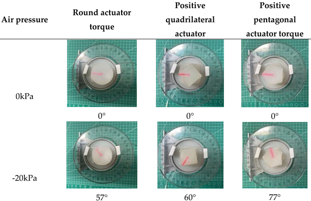
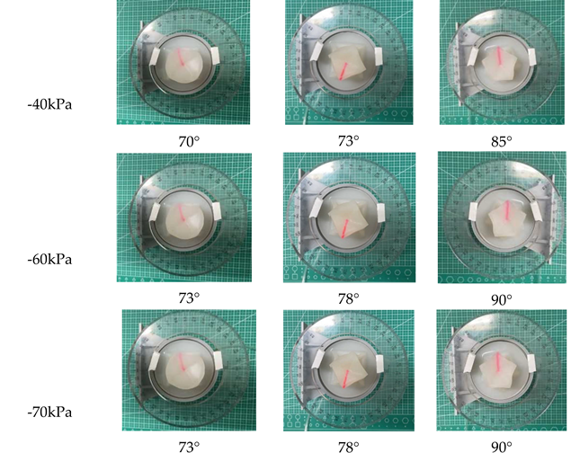
After placing the flexible torsion module in the middle of the measuring platform, the air pressure input to the actuator is controlled by turning the regulator valve. The initial angle of the torsion actuator was preset at 0º and the negative pressure was gradually increased to measure the angle of the torsion actuator at 10kPa intervals. The data was averaged over several measurements and measured for each of the three different bottom surfaces of the torsion actuator. The table shows that the torsional angle of the torsional actuator differs for the three different shapes of the bottom surface when the same negative pressure is applied. The maximum torsion angle for the quadrilateral base actuator is 78°, the maximum torsion angle for the pentagonal base actuator is 90° and the maximum torsion angle for the circular base actuator is 73°. The three actuators have a large variation in torsional angle from 0 to -10 kPa, a gentle variation in torsional angle from -10 kPa to -50 kPa and a maximum torsional angle at the same time at -50 kPa.

Table 5.
Torsional angle-pressure diagram for torsional actuators with different base shapes.
 |
 |
3.1.3. Experimental Measurement of Axial Length Variation of Flexible Torsional Actuators
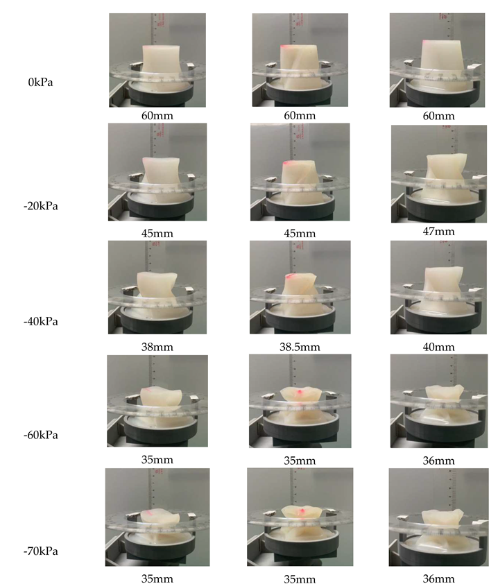
In the process of torsional actuator contraction torsion, the inclined plane of the actuator tilts and collapses inward, resulting in the axial contraction of the actuator. Therefore, the torsional actuator will perform two kinds of motion, linear motion and torsional motion, under the drive of negative pressure. This measurement experiment will measure the axial length change of the actuator with different shapes in the torsional process, and calculate the average value through multiple measurements. The data of three torsional actuators with different bottom surfaces were measured respectively to obtain Table 6 and Figure 16.
It can be seen from Figure 16 that under negative pressure of 0kPa~-70kPa, torsional actuators with different bottom surfaces have little difference in their axial lengths, because torsional actuators with regular quadrilateral and circular bottom surfaces have the same number of supporting axes, which makes their axial length change curves almost the same with only slight differences. Compared with the regular quadrilateral and circular bottom surface, the regular pentagonal torsional actuator has an extra axis on the side, making its final axial length 2mm longer than the other two.
Table 6.
Axial length-pressure diagram of torsion actuator with different bottom shapes.
| Air pressure | Circular actuator | Regular quadrilateral actuator | Regular pentagon actuator |
 | |||
3.2. Software Torsion Gripper System Overall Experiment
(1) Grab actuator grab experiment
The gripper grasps the target as shown in Figure 17. The conditions for success of its grasping action are as follows: no falling occurs in the process of effectively grasping objects. As shown in the following picture, the captured items are USB flash drive (9g), circular industrial switch (31g), L-shaped Allen wrench (13g), and quail egg (11g). The software gripper simulates grabbing objects, as shown in Figure 18.
The measurement of the gripping efficiency of the soft gripping actuator is guided by the "Standard Test Method for Responsive Robots". The objective is to capture statistically significant functional data according to the standard test method. Through many experiments, it can be concluded that, first, the soft body is more stable when grasping cylindrical objects. The reason is that when the three knuckles are bent, the surface is in an arc state, forming an enveloping structure for the objects, which can grasp the target objects more stably. When the soft grasp actuator grabs fragile objects on the surface, such as quail eggs, because the silicone rubber material is soft, the finger cavity of the soft grasp can adaptively change the current state according to the shape of the object when grasping the object, so that it is completely fitted to the surface of the target object, so it is suitable for grasping fragile and fragile objects on the surface. At the same time, due to the structure of the front end of the finger cavity, it is found in the experiment that the soft body is easy to fall when grasping small objects such as L-shaped wrench.
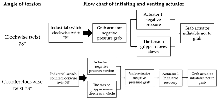
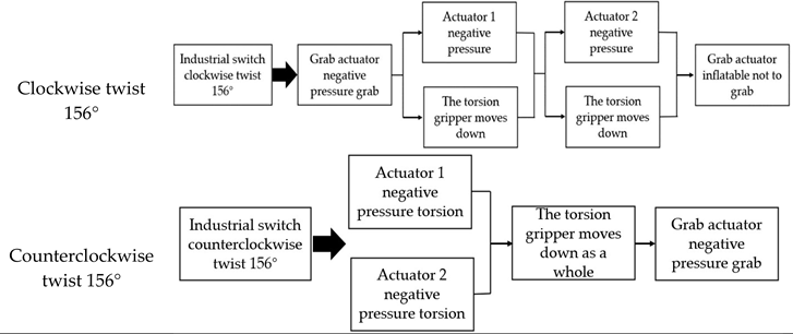
(2) Torsional grab experiment
In this experiment, the platform will be built in the form of the second modular combination, to control the torsional actuator 1, torsional actuator 2, grab the actuator suction and ventilation, to achieve the industrial switch torsion -78°~78°. The experimental diagram of this experiment is shown in Figure 19.
In this experiment, the industrial switch will be twisted through the aspiration and inflation of torsional actuator 1 and torsional actuator 2. The flow chart of the control system is shown in Table 7.
It can be seen from above that the torsional Angle of the regular quadrilateral torsional actuator is 78° and its axial length is 35mm under the pressure of -70kPa. Therefore, in the process of torsion, a single torsion actuator will be accompanied by a 25mm height expansion. Therefore, in the process of torsion of the actuator, the grip should be moved down a certain distance as a whole.
(3) Industrial switch torsion experiment
After analyzing the inflating and venting sequence of each module, the industrial switch will be tested for clockwise and counterclockwise torsion. This experiment will measure the maximum torsion Angle of the soft gripper to the industrial switch in practice, and analyze whether there is any error between the actual torsion Angle and the theoretical torsion Angle, and analyze and optimize the error. The experimental process is shown in Figure 20.
The measured torsion Angle of the actual industrial switch is 60° when driving actuator 1, and 115° when driving actuator 1 and actuator 2. The reasons why the theoretical torsion Angle is smaller than the torsion Angle of the actuator are as follows: ① There is relative sliding between the grasping actuator and the industrial switch in the torsion process; ② Due to the weight of the actuator quick assembly interface, the actual torsion Angle of the actuator is less than 78°; ③ There are errors in the positioning process of soft actuator. The reason why the torsion Angle of actuator 2 is smaller than that of actuator 1 is that the gravity of actuator 2 is greater than that of actuator 1, so the torsion Angle is smaller than that of actuator 1.
(4) The experiment of torsional objects stuck in space
This experiment will simulate the Angle adjustment of the workpiece in assembly line production, and the process of Angle adjustment of the workpiece is shown in Figure 21.
It is measured that the actual torsion Angle of the workpiece is 63° when only actuator 1 is driven. When actuator 1 and actuator 2 are driven, the actual torsion Angle is 122°. After analysis, the actual torsion Angle is smaller than the theoretical Angle for the following reasons: (1) The weight of the workpiece and the interface offset a part of the torsion Angle; (2) There are errors in the positioning of the actuator.
To solve the above problems, if the actuator can be accurately moved to the industrial switch center, the torsion Angle will be increased. After that, the RGB-D visual algorithm is used to identify and determine the position of the industrial switch, and the positioning accuracy of the industrial switch is optimized through continuous comparison practice, so that the software gripper can move to the top of the target industrial switch center more precisely, and the deviation of the torsion Angle caused by inaccurate positioning is eliminated. After continuous grasping practice, the positioning error of the soft actuator in the left and right direction of the industrial switch was reduced to 1mm, and the torsion Angle of the industrial switch was also increased from 60° to 70°.
4. Conclusions
A modular software torsion grasping system is designed that can assemble actuators by modular assembly and make up for the shortcomings of traditional software grippers in torsion function. The actuating principle of the two actuators is explained, and the relevant parameters that may affect the actuating performance of the actuators are analyzed by using ABAQUS as the simulation platform. Combined with the results of the simulation experiment, the optimal structural design parameters of the torsional actuator and grasping actuator were optimized to improve the performance of the actuator.
In the actual torsion process, due to the sliding between the grasping actuator and the industrial switch and the weight of the quick assembly interface of the actuator, the actual torsion angle of the actuator is less than 78°, and the actual torsion angle is 60°. Then use the RGB-D visual algorithm to continuously compare and practice to optimize the gripper positioning so that the twist angle can be increased to 70°, which can meet the angle requirements of twisting the target item.
This paper introduces and uses the RGB-D algorithm to optimize the grasping process of the soft torsion gripper and the grasping accuracy of the soft torsion gripper when facing the target object by combining it with continuous contrast training. The actuating performance of the manufactured soft actuator samples with different bottom surfaces was tested on the test platform. A modular torsional grasping experimental test platform was built to test the torsional angle of the modular torsional gripper in the actual grasping process, and the grasping accuracy was optimized by the RGB-D algorithm, achieving a torsional angle of 70° for the single torsional actuator.
Author Contributions
Conceptualization, Z.X. H.L. and C.Y.; methodology, H.L.; software, Z.X.; validation, H.L. C.Y. and X.N.; formal analysis, W.F.; investigation, H.Y.; resources, H.L.; data curation, H.L.; writing —original draft preparation, H.L. and C.Y.; writing— review and editing, Z.X.; visualization, C.Y. and Z.X.; supervision, H.L.; project administration, R.Z.; funding acquisition, R.Z. All authors have read and agreed to the published version of the manuscript.
Funding
We gratefully acknowledge the financial support of this research by the following project: Zhejiang Province Bellwethers Project (Grant No. 2023C03126 ).
Data Availability Statement
Not applicable.
Conflicts of Interest
The authors declare no conflict of interest.
References
- Rus, D.; Tolley, M.T. Design, fabrication and control of soft robots. Nature 2015, 521, 467–475. [Google Scholar] [CrossRef]
- Wang, M.; Hao, Y.; Yang, X.; Wen, L. Soft robotics: Structure, actuation, sensing and control. Journal of Mechanical Engineering 2017, 53, 1–13. [Google Scholar]
- Achilli, G.M.; Valigi, M.C.; Salvietti, G.; Malvezzi, M. Design of Soft Grippers with Modular Actuated Embedded Constraints. Robotics 2020, 9, 105. [Google Scholar] [CrossRef]
- Giannaccini, M.E.; Xiang, C.; Atyabi, A.; et al. Novel Design of a Soft Lightweight Pneumatic Continuum Robot Arm with Decoupled Variable Stiffness and Positioning. Soft Robotics 2017, 5, 54–70. [Google Scholar] [CrossRef] [PubMed]
- Tawk, C.; Alici, G. Finite Element Modeling in the Design Process of 3D Printed Pneumatic Soft Actuators and Sensors. Robotics 2020, 9, 52. [Google Scholar] [CrossRef]
- Trimmer, M.B.; Ewoldt, P.R.H.; Kovac, M.; Lipson, H.; Lu, N.; Shahinpoor, M.; Majidi, C. At the cross-roads: Interdisciplinary paths to soft robots. Soft Robot 2014, 1, 63–69. [Google Scholar] [CrossRef]
- Huang, Y.; Yu, Q.; Su, C.; Jiang, J.; Chen, N.; Shao, H. Light-Responsive Soft Actuators: Mechanism, Materials, Fabrication, and Applications. Actuators 2021, 10, 298. [Google Scholar] [CrossRef]
- Morin, S.A.; Shepherd, R.F.; Kwok, S.W.; Stokes, A.A.; Nemiroski, A.; Whitesides, G.M. Camouflage and Display for Soft Machines. Science 2012, 337, 828–832. [Google Scholar] [CrossRef]
- Copaci, D.; Blanco, D.; Moreno, L.E. Flexible Shape-Memory Alloy-Based Actuator: Mechanical Design Optimization According to Application. Actuators 2019, 8, 63. [Google Scholar] [CrossRef]
- Shen, Z.; Zhang, Y.; Wang, N. A Conceptual Design of Snake-like Soft Robot with Multiple Motion Modes. CFHI Technology 2022, 1, 12–15. [Google Scholar]
- James, W.; Thomas, Z.; Cory, H.; et al. Soft Robotics: A Review of Recent Developments of Pneumatic Soft Actuators. Actuators 2020, 9, 3. [Google Scholar]
- Wang, H. Research Progress of Soft Robot. Journal of South China University of Technology (Natural Science Edition) 2020, 2, 94–106. [Google Scholar]
- Ma, N.; Yao, Y.; Wang, Q.; Niu, C.; Dong, X. Properties and mechanical model of a stiffness tunable viscoelastic damper based on electrorheological elastomers. Smart Materials and Structures 2020, 2020. 29, 045041. [Google Scholar] [CrossRef]
- Nikafrooz, N.; Leonessa, A. A Single-Actuated, Cable-Driven, and Self-Contained Robotic Hand Designed for Adaptive Grasps. Robotics 2021, 10, 109. [Google Scholar] [CrossRef]
- Li, Y.; Li, J. Research progress in durable super-hydrophobic surface based on PDMS. China Plastics 2022, 36, 167–176. [Google Scholar]
- Yang, M.; Zhou, S.; Liu, F. Research progress of intelligent hydrogel. Chemical Engineer 2015, 23, 66–71. [Google Scholar]
- Cursi, F.; Mylonas, G.P.; Kormushev, P. Adaptive Kinematic Modelling for Multiobjective Control of a Redundant Surgical Robotic Tool. Robotics 2020, 9, 68. [Google Scholar] [CrossRef]
- Trivedi, D.; Rahn, C.D.; Kier, W.M.; Walker, I.D. Soft robotics: Biological inspiration, state of the art, and future research. Appl. Bionics Biomech. 2008, 5, 99–117. [Google Scholar] [CrossRef]
- Wehner, M.; Truby, R.L.; Fitzgerald, D.J.; et al. An integrated design and fabrication strategy for entirely soft, autonomous robots. Nature 2016, 536, 451–455. [Google Scholar] [CrossRef]
- Huang, J.; Wang, S.; Lyu, S.; Fu, F. Preparation of a robust cellulose nanocrystal superhydrophobic coating for self-cleaning and oil-water separation only by spraying. Industrial Crops & Products 2018, 122, 438–447. [Google Scholar]
- Shan, H.; Liu, J. Fabrication of the PDMS Multi-Layer Mushroom-Shaped Microstructures. Micronanoelectronic Technology 2020, 5, 395–398. [Google Scholar]
- Xue, C.; Li, M.; Guo, X.; Li, X.; An, Q.; Jia, S. Fabrication of superhydrophobic textiles with high water pressure resistance. Surface & Coatings Technology 2017, 310, 134–142. [Google Scholar]
- Jiao, Z.; Ji, C.; Zou, J.; Yang, H.; Pan, M. Vacuum-Powered Soft Pneumatic Twisting Actuators to Empower New Capabilities for Soft Robots. Advanced Materials Technologies 2019, 4, 1800429. [Google Scholar] [CrossRef]
- Calisti, M.; Giorelli, M.; Levy, G.; et al. An Octopus-bioinspired Solution to Movement and Manipulation for Soft Robots. Bioinspiration & Biomimetics 2011, 6, 036002. [Google Scholar]
- Ilievski, F.; Mazzeo, A.D.; Shepherd, R.E.; et al. Soft Robotics for Chemists. Angewandte Chemie 2011, 50, 1890–1895. [Google Scholar] [CrossRef] [PubMed]
- Manti, M.; Hassan, T.; Passetti, G.; et al. A Bioinspired Soft Robotic Gripper for Adaptable and Effective Grasping. Soft Robotics 2015, 2(3), 107–116. [Google Scholar] [CrossRef]
- Chen, S.; Pang, Y.; Yuan, H.; et al. Smart Soft Actuators and Grippers Enabled by Self-Powered Tribo-Skins. Advanced Materials Technologies 2020, 1901075. [Google Scholar] [CrossRef]
- Ma, L.K.; Zhang, Y.Z.; Liu, Y.; Zhou, K.; Tong, X. Computational Design and Fabrication of Soft Pneumatic Objects with Desired Deformations. ACM Transactions on Graphics 2017, 36, 1–12. [Google Scholar] [CrossRef]
- Scharff, R.B.N.; Wu, J.; Geraedts, J.M.P.; & Wang, C.C.L. Reducing Out-of-Plane Deformation of Soft Robotic Actuators for Stable Grasping. IEEE International Conference on Soft Robotics 2019, 8722823.
- Ha, Q.; Watanabe, K.; Karasawa, T.; et al. Mfnet: Towards real-time semantic segmentation for autonomous vehicles with multi-spectral scenes. IEEE/RSJ International Conference on Intelligent Robots and Systems 2017, 5108–5115. [Google Scholar]
Figure 1.
Schematic diagram of the modular design of the flexible torsion gripper.
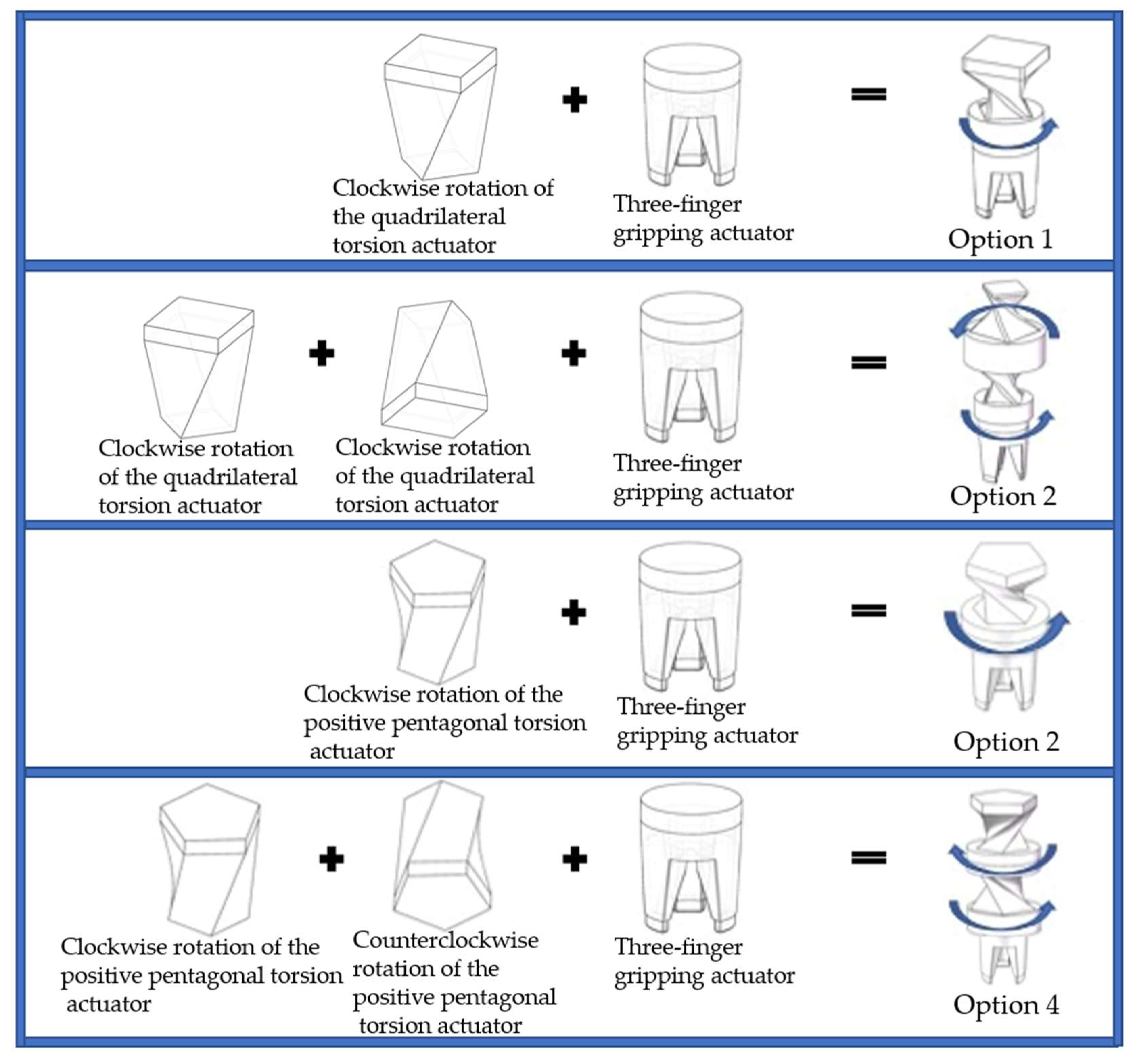
Figure 2.
Positive quadrilateral soft torsion actuator mould. (a) Upper mould A, (b) Lower mould B, (c) Integral mould, (d) Pouring mould.
Figure 2.
Positive quadrilateral soft torsion actuator mould. (a) Upper mould A, (b) Lower mould B, (c) Integral mould, (d) Pouring mould.
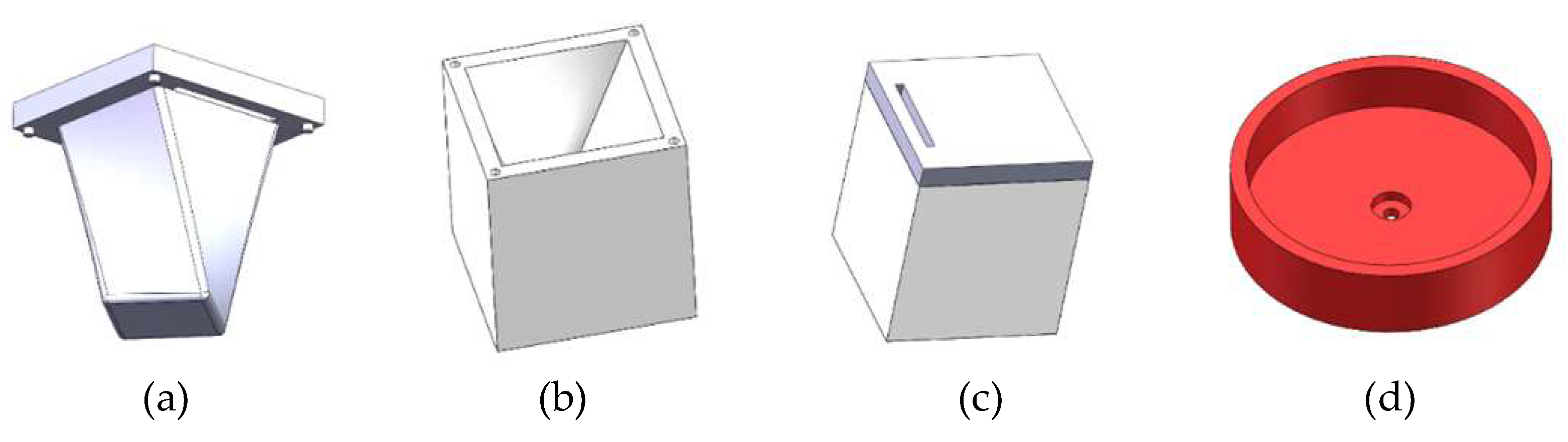
Figure 3.
Manufacturing process of torsional actuator.
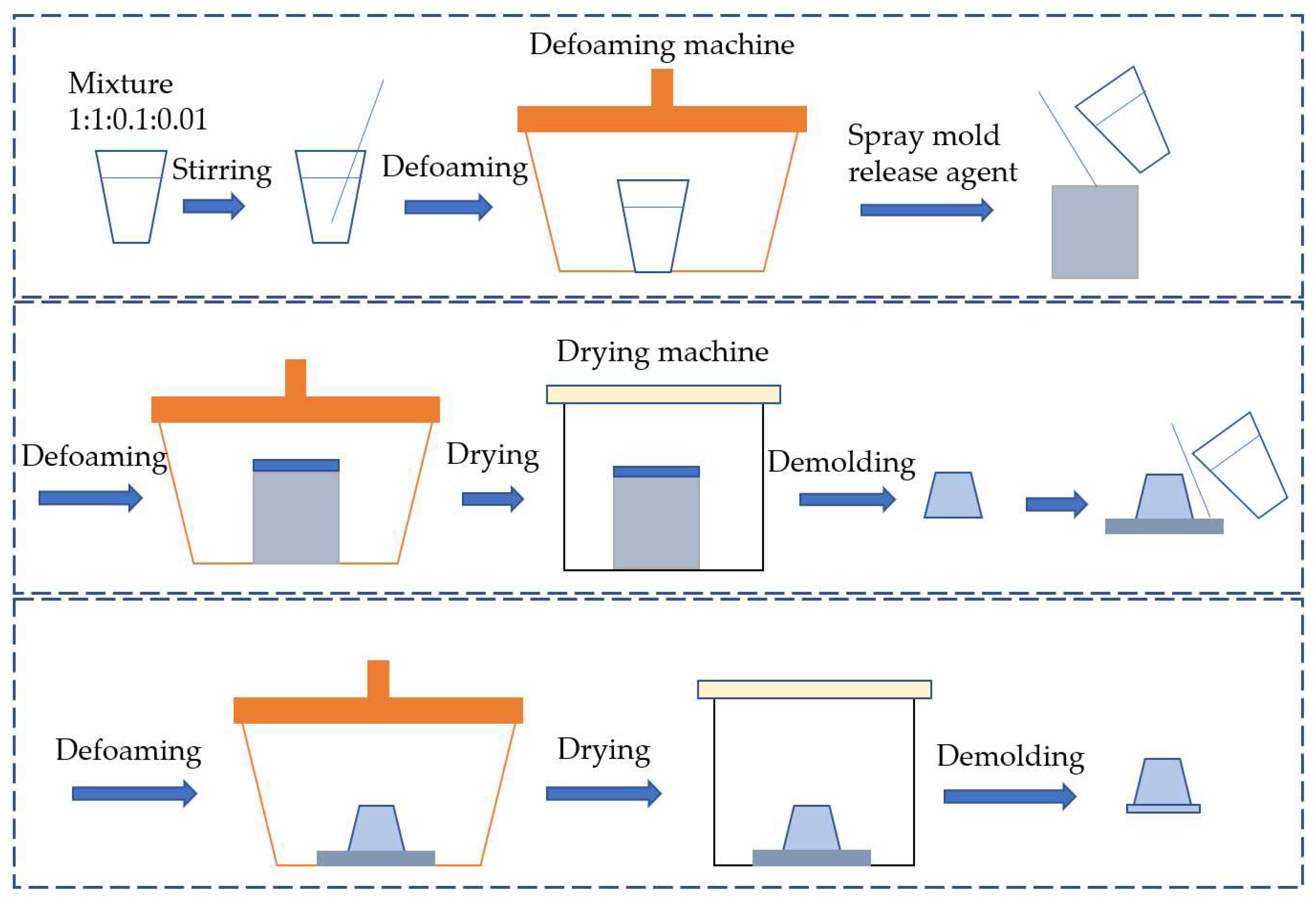
Figure 4.
Pre-preparation work for a flexible torsion actuator. (a) Rubber release agent, (b) Ecoflex 00-30 silicone rubber, (c) PDMS, (d) Vacuum defoamer, (e) Configured silicone rubber solution.
Figure 4.
Pre-preparation work for a flexible torsion actuator. (a) Rubber release agent, (b) Ecoflex 00-30 silicone rubber, (c) PDMS, (d) Vacuum defoamer, (e) Configured silicone rubber solution.
Figure 5.
Positive quadrilateral torsional actuator. (a) Upper part of the actuator, (b) Diagram of the casting process in the lower half of the mould, (c) Overall actuator, (d) Bottom surface of the actuator.
Figure 5.
Positive quadrilateral torsional actuator. (a) Upper part of the actuator, (b) Diagram of the casting process in the lower half of the mould, (c) Overall actuator, (d) Bottom surface of the actuator.
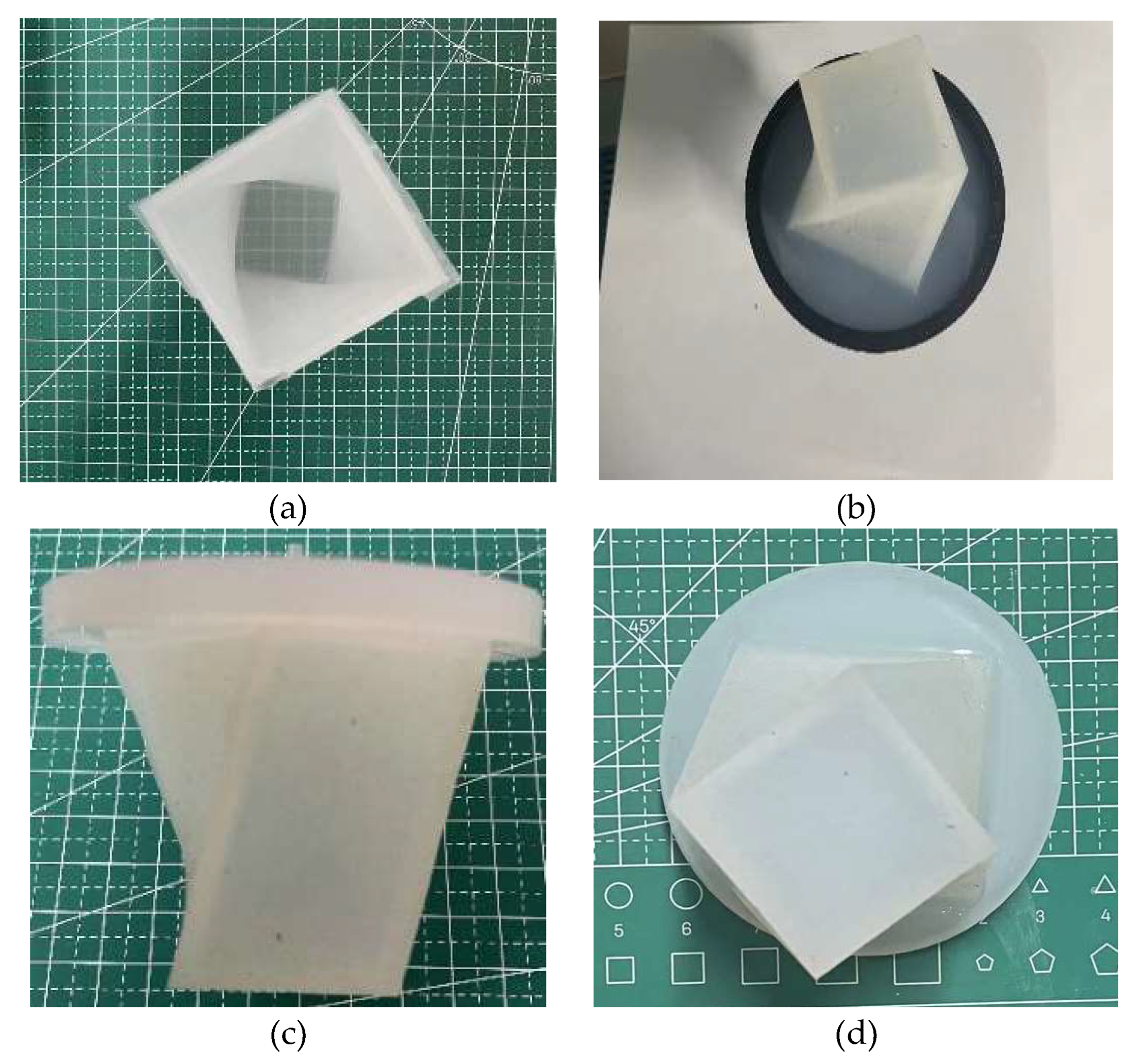
Figure 6.
Schematic diagram of the three-finger gripping actuator structure. (a) Isometric drawing, (b) Single finger section.
Figure 6.
Schematic diagram of the three-finger gripping actuator structure. (a) Isometric drawing, (b) Single finger section.
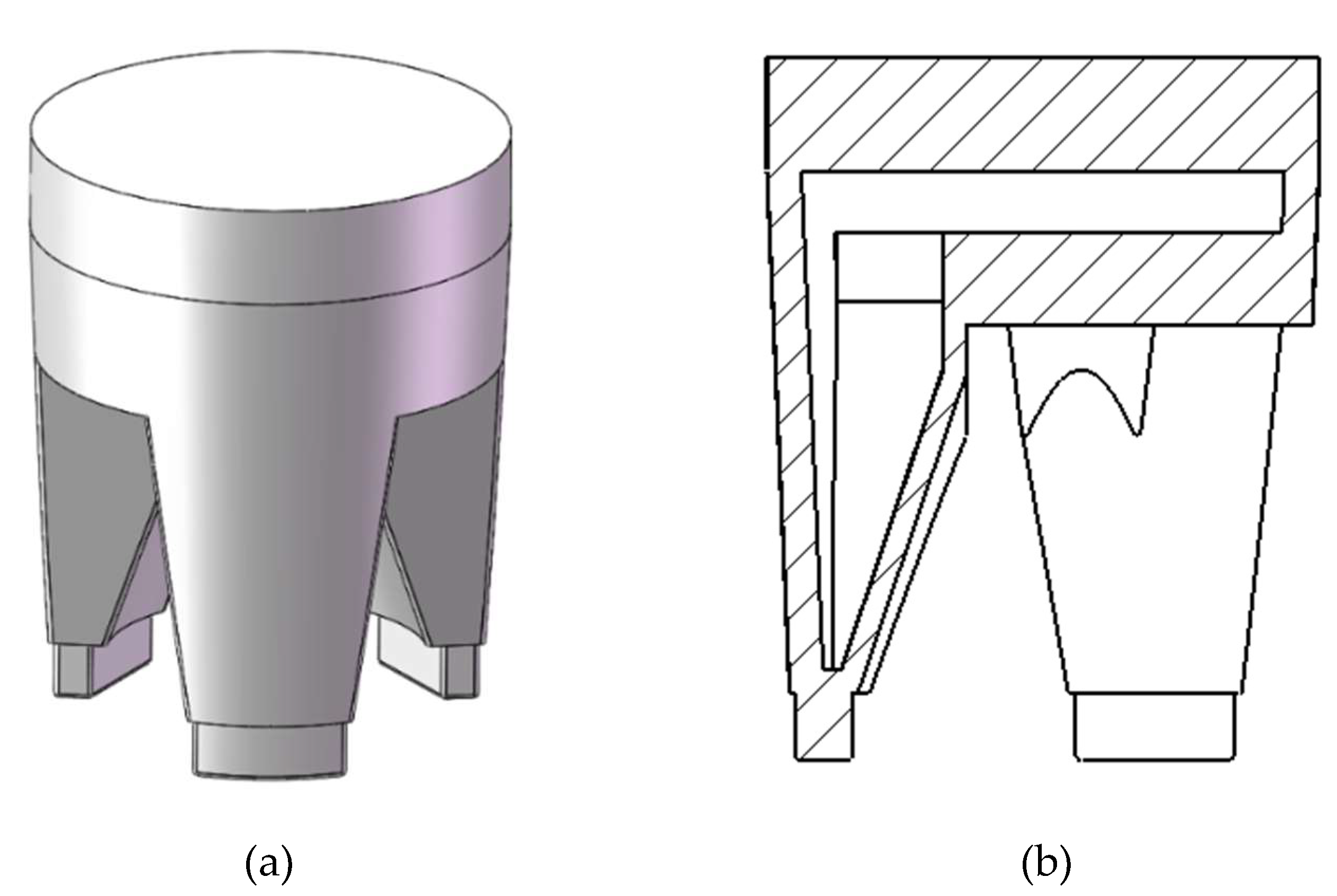
Figure 7.
Deformation results of the positive quadrilateral soft torsion actuator. (a) 0kPa, (b) -70kPa.
Figure 7.
Deformation results of the positive quadrilateral soft torsion actuator. (a) 0kPa, (b) -70kPa.
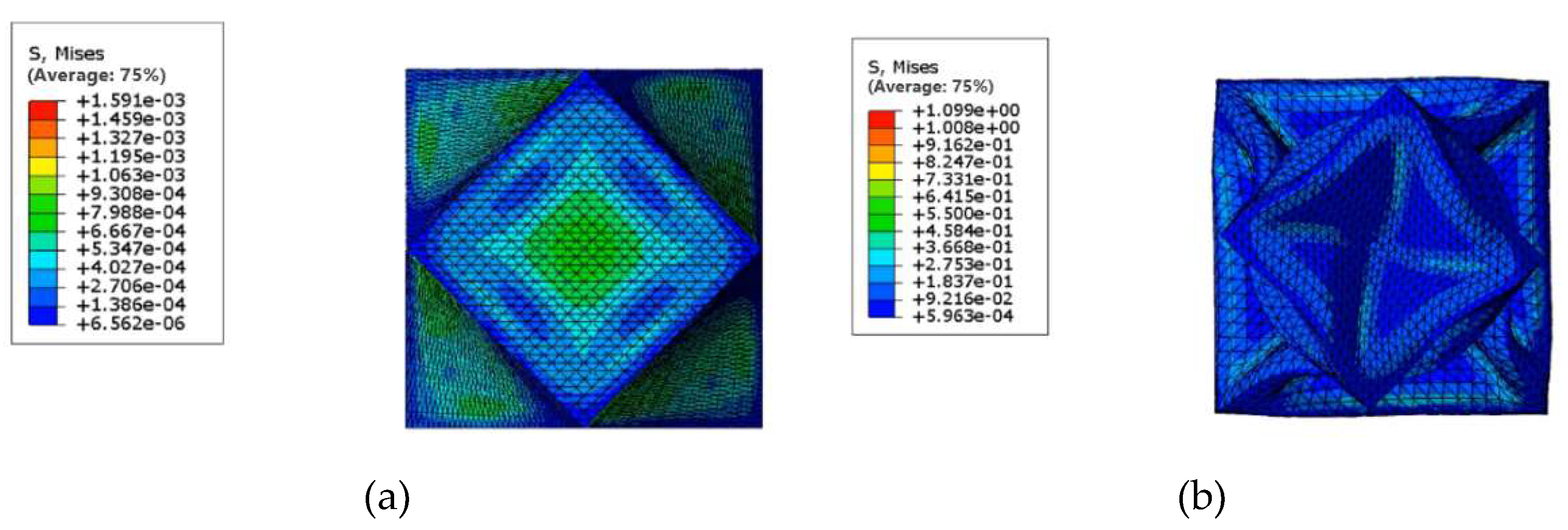
Figure 8.
Simulation results of torsional actuator with different side rib thickness at 70kPa. (a) Thickness of side ribs 2mm, (b) Thickness of side ribs 2.5mm, (c) Thickness of side ribs 3mm, (d) Thickness of side ribs 2mm.
Figure 8.
Simulation results of torsional actuator with different side rib thickness at 70kPa. (a) Thickness of side ribs 2mm, (b) Thickness of side ribs 2.5mm, (c) Thickness of side ribs 3mm, (d) Thickness of side ribs 2mm.
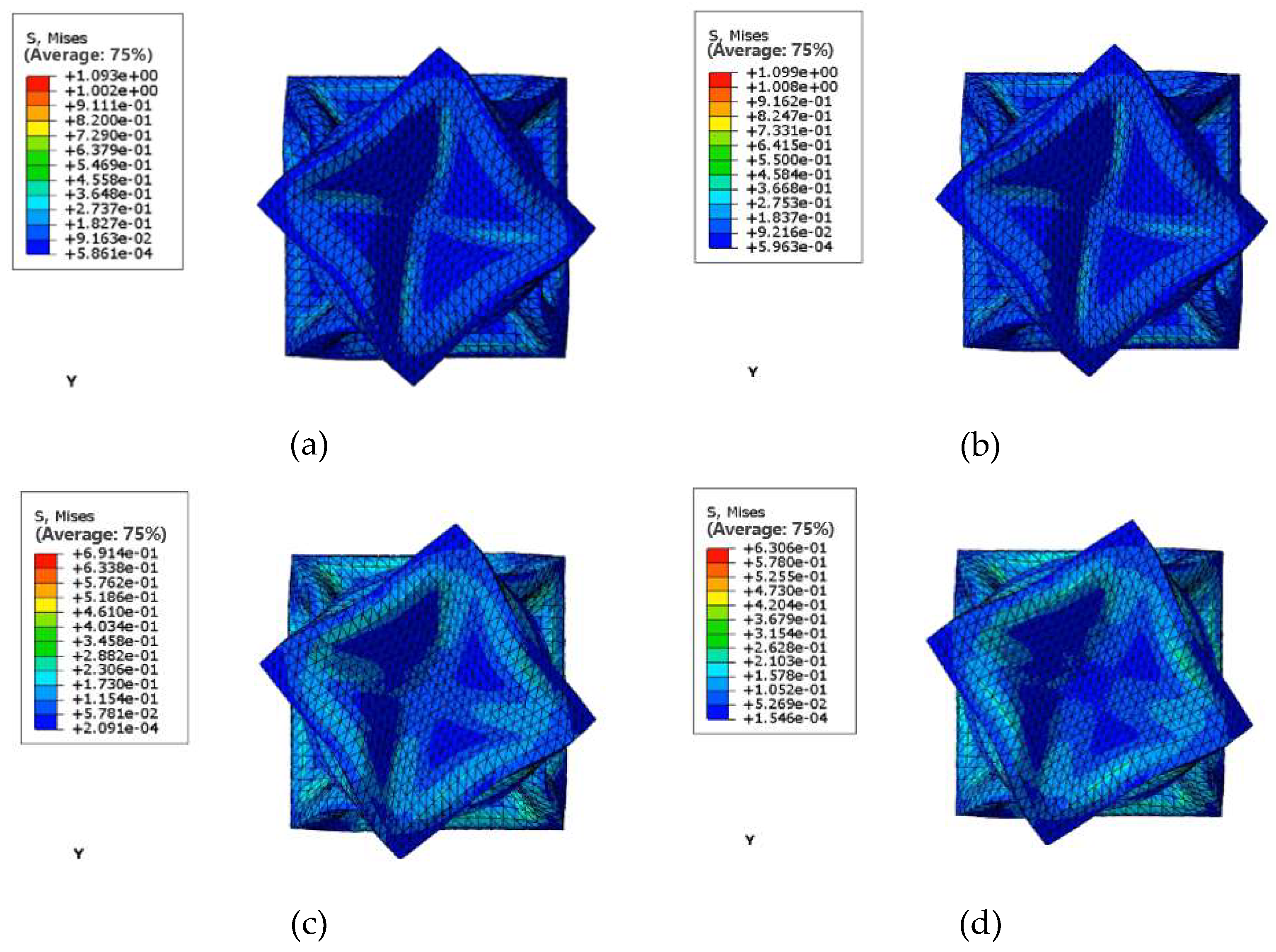
Figure 9.
Diagram of the results of the positive pressure finite element analysis. (a) 20 kPa front view, (b) 30 kPa front view, (c) 40 kPa front view, (d) 50 kPa front view, (e)(f) 50 kPa profile.
Figure 9.
Diagram of the results of the positive pressure finite element analysis. (a) 20 kPa front view, (b) 30 kPa front view, (c) 40 kPa front view, (d) 50 kPa front view, (e)(f) 50 kPa profile.
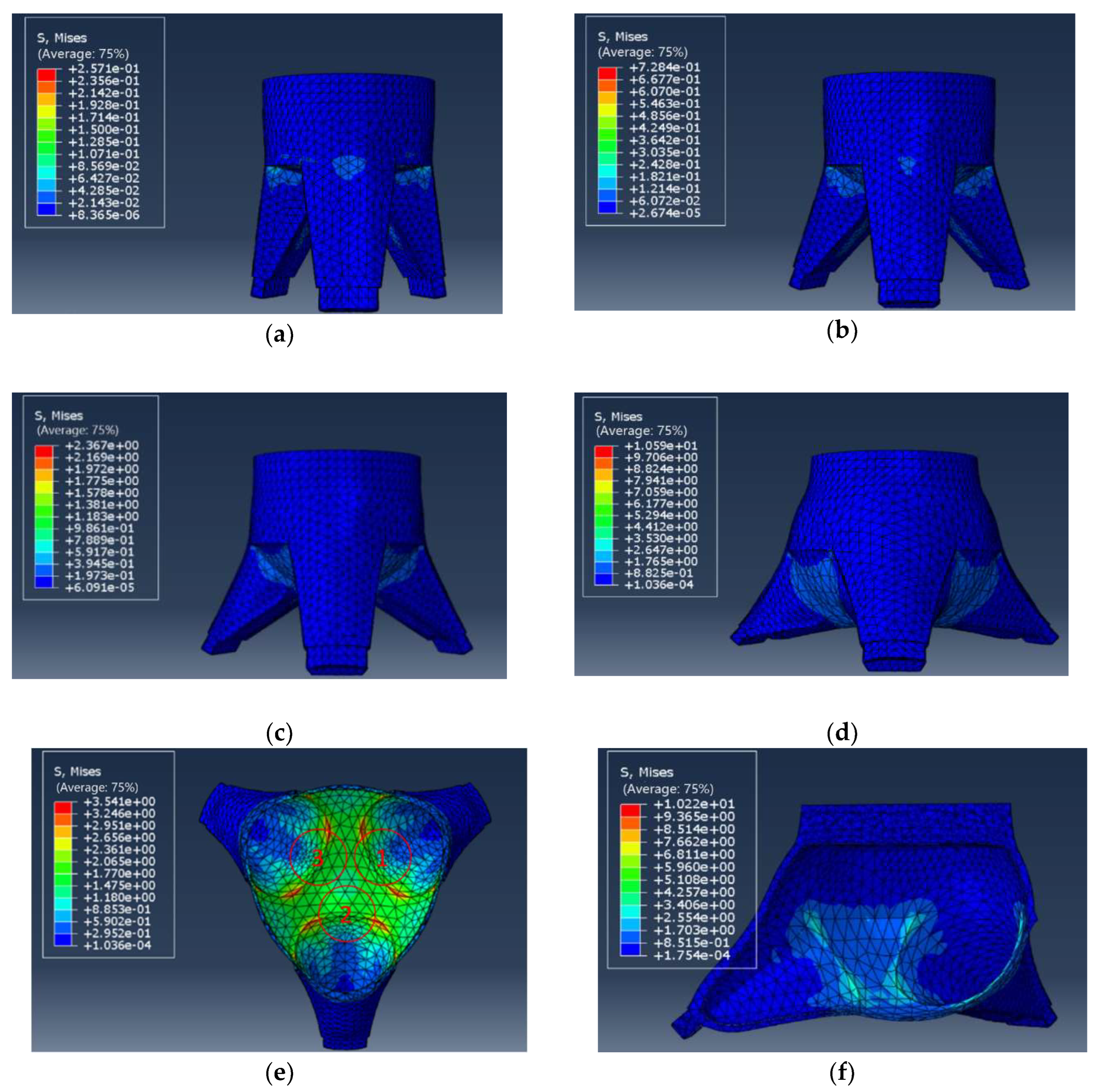
Figure 10.
Deformation of the bottom of the finger cavity of the gripping actuator after parameter changes. (a) Diagram showing the change in thickness of the base of the finger cavity, (b) Deformation diagram of the gripping actuator under positive pressure at 50kPa.
Figure 10.
Deformation of the bottom of the finger cavity of the gripping actuator after parameter changes. (a) Diagram showing the change in thickness of the base of the finger cavity, (b) Deformation diagram of the gripping actuator under positive pressure at 50kPa.
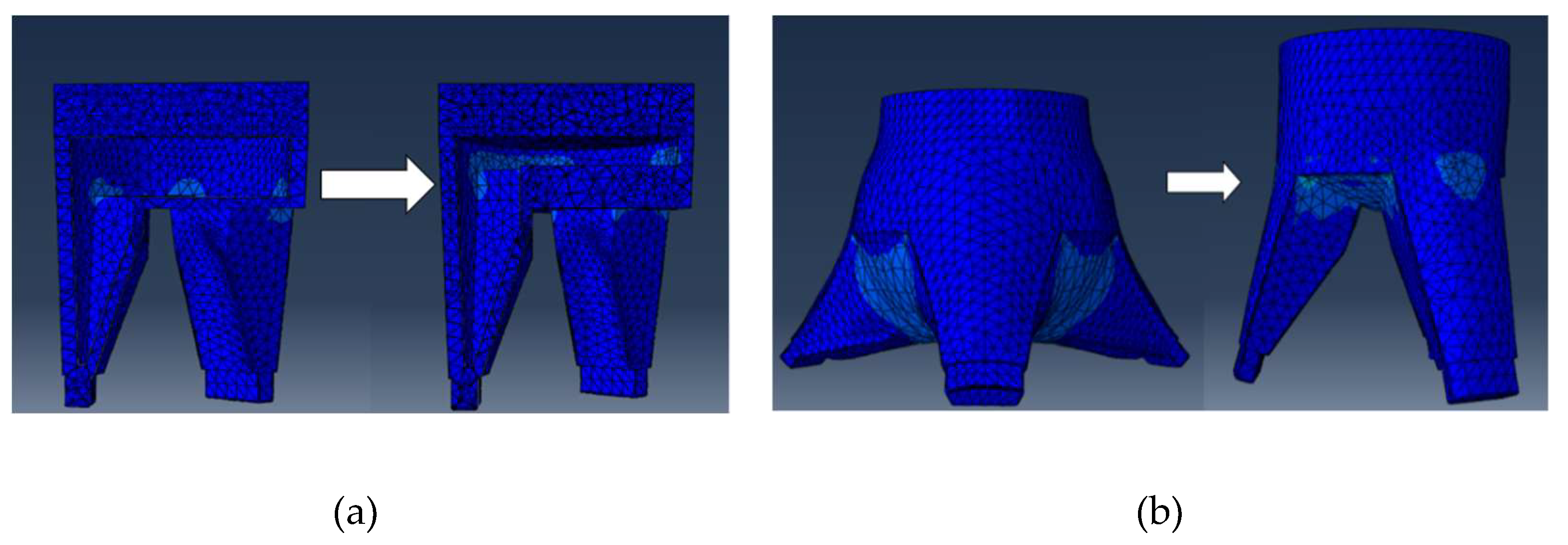
Figure 11.
Results of the negative pressure finite element analysis of the gripper actuator.
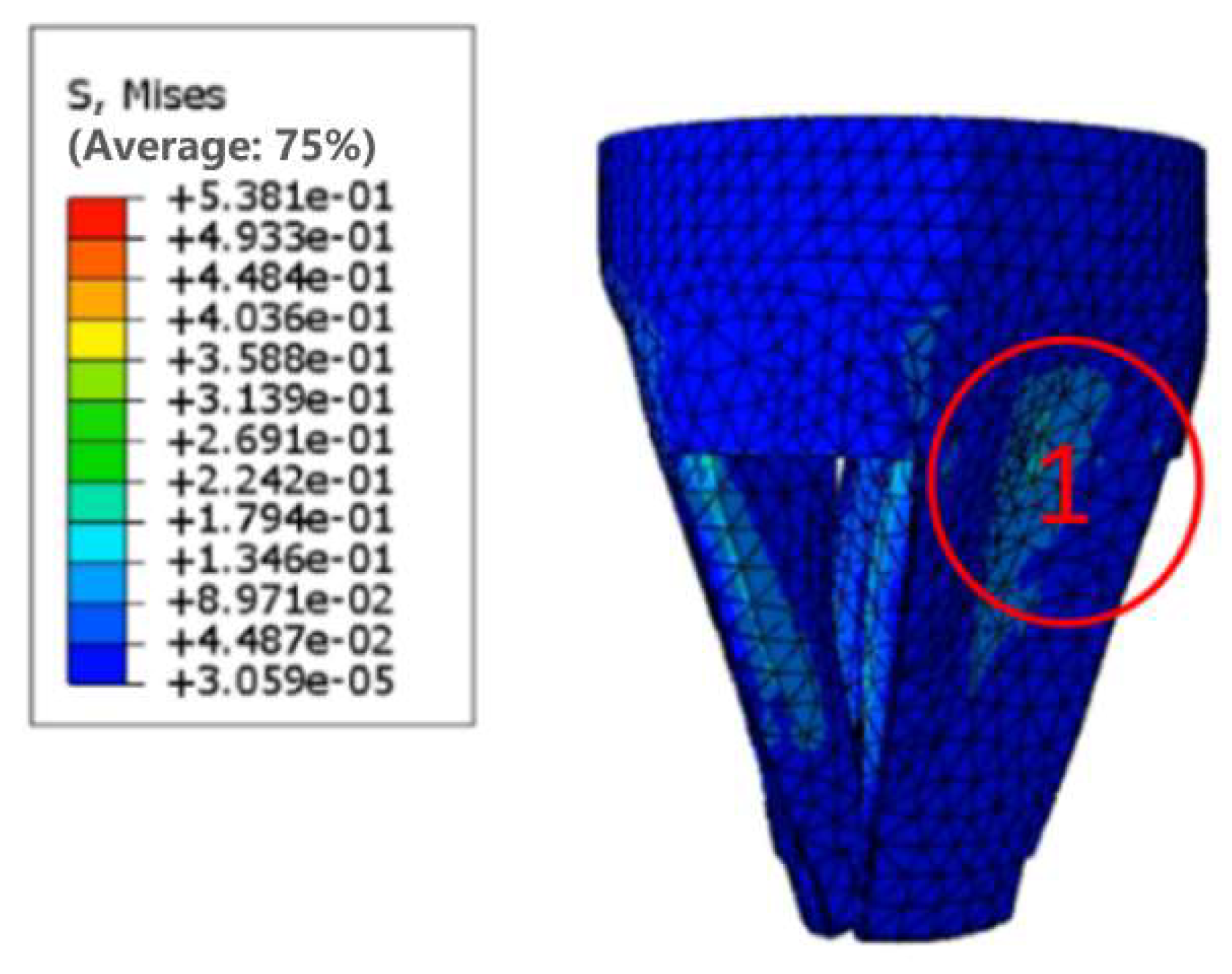
Figure 12.
Results of the negative pressure finite element analysis of the gripping actuator after changing the finger cavity thickness parameter.
Figure 12.
Results of the negative pressure finite element analysis of the gripping actuator after changing the finger cavity thickness parameter.
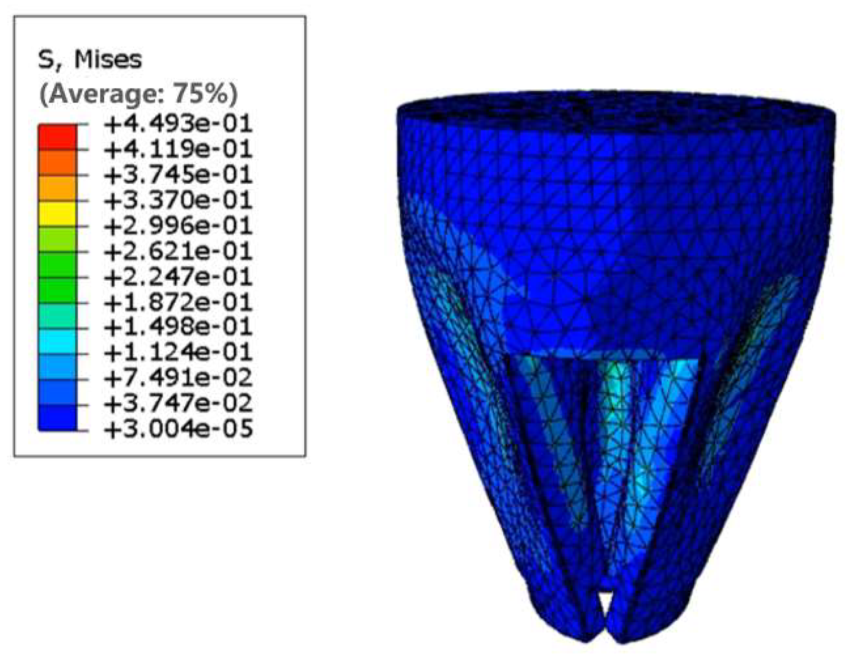
Figure 13.
Flow chart of algorithm model.
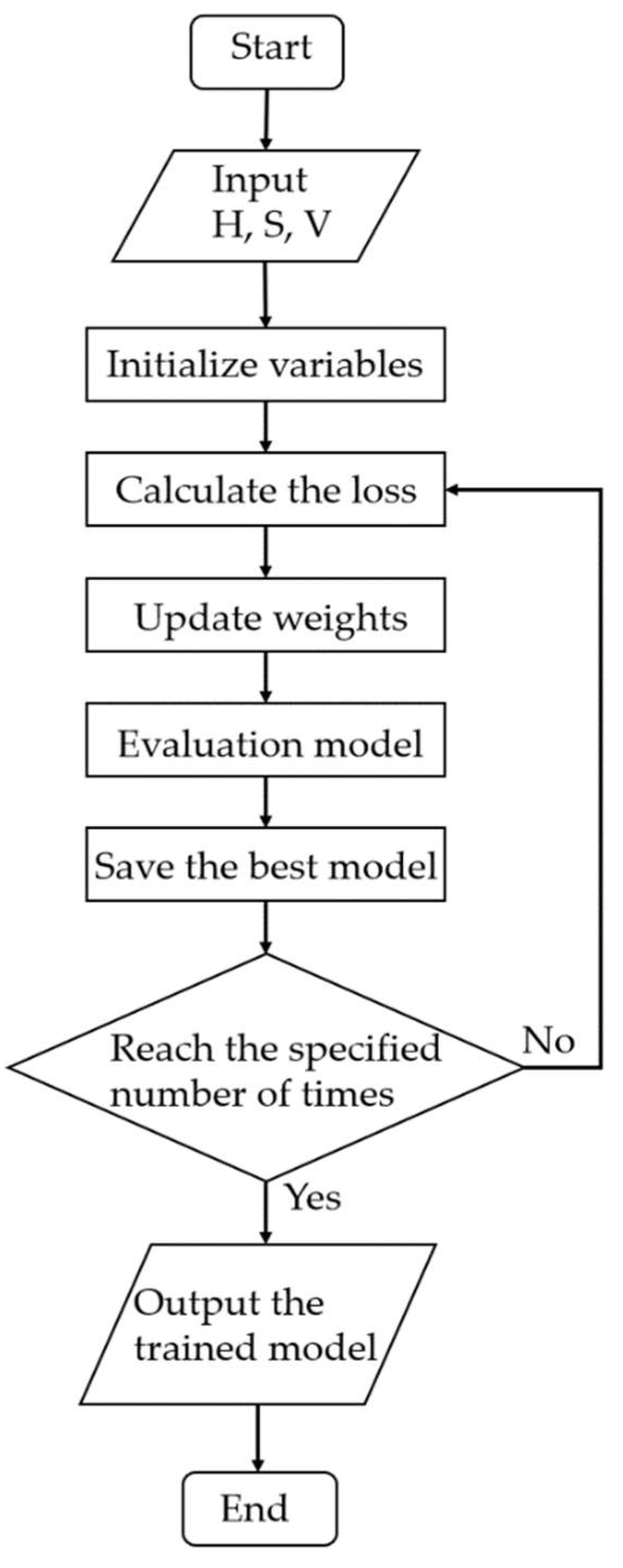
Figure 14.
Schematic diagram of the operation of the flexible actuator.
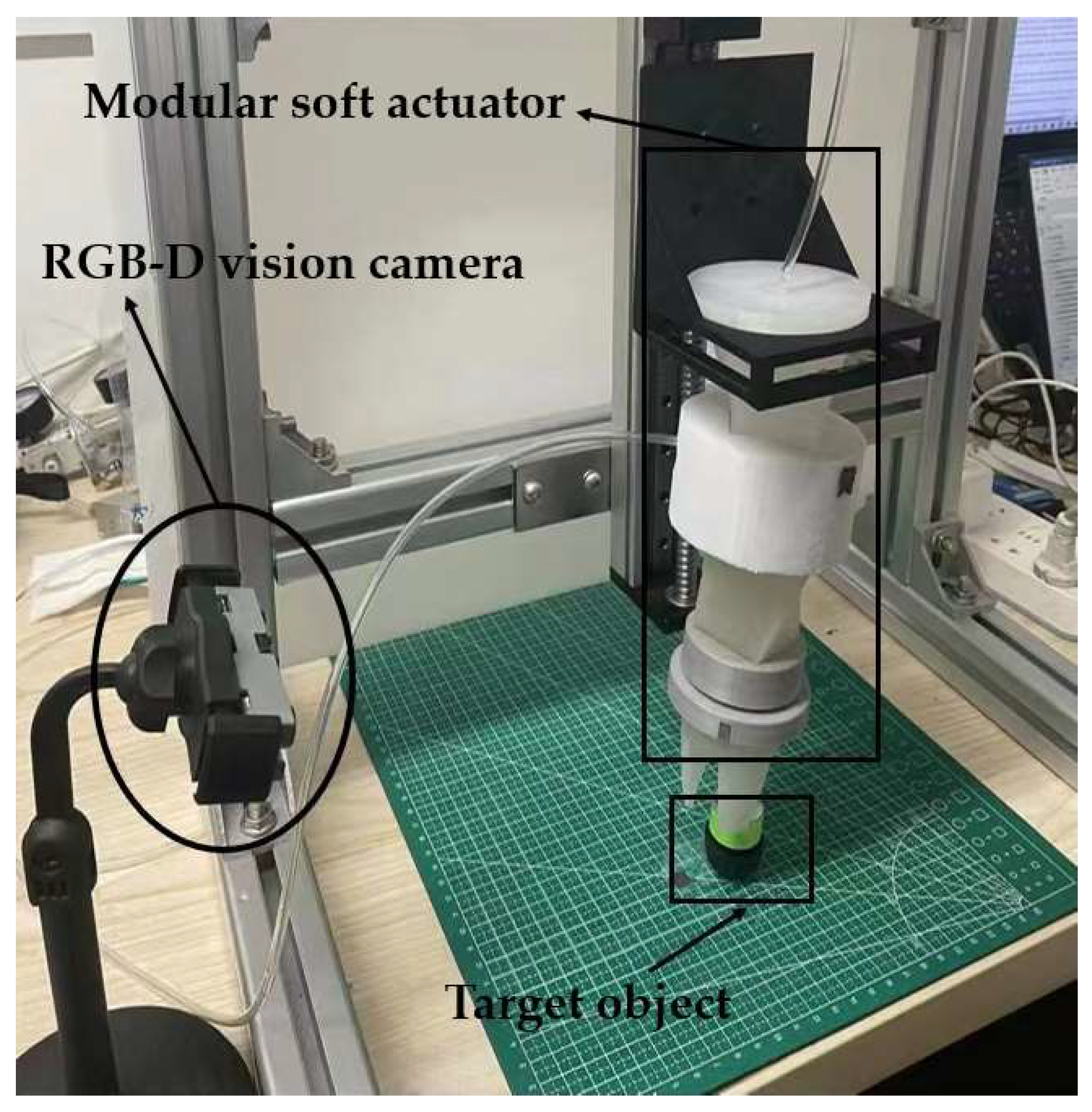
Figure 15.
Torsional actuator with different base shapes - 70 kPa torque measurement. (a) Positive quadrilateral bottom actuator, (b) Positive pentagonal bottom actuator, (c) Round bottom actuator.
Figure 15.
Torsional actuator with different base shapes - 70 kPa torque measurement. (a) Positive quadrilateral bottom actuator, (b) Positive pentagonal bottom actuator, (c) Round bottom actuator.
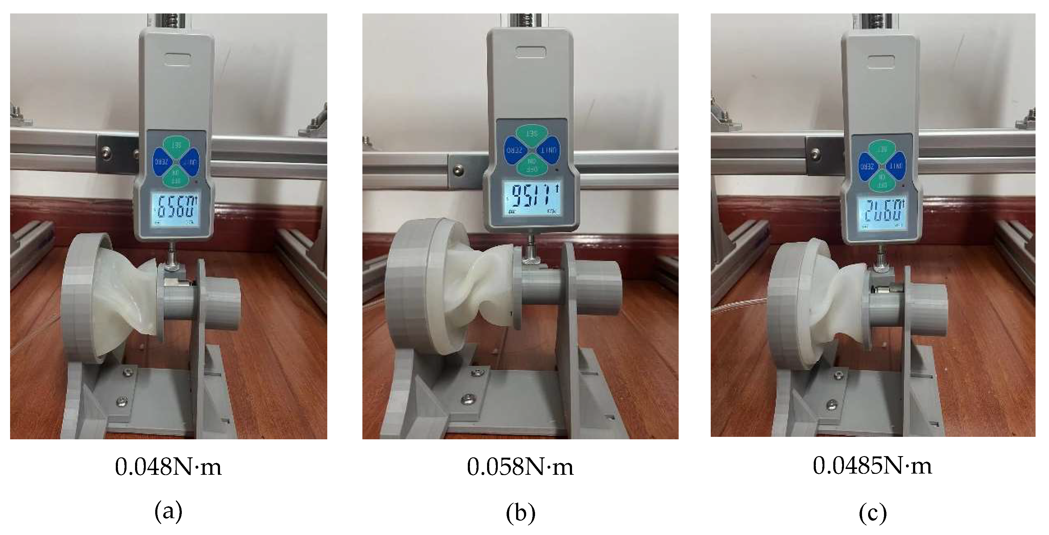
Figure 16.
Axial length characteristics of soft torsion actuator.
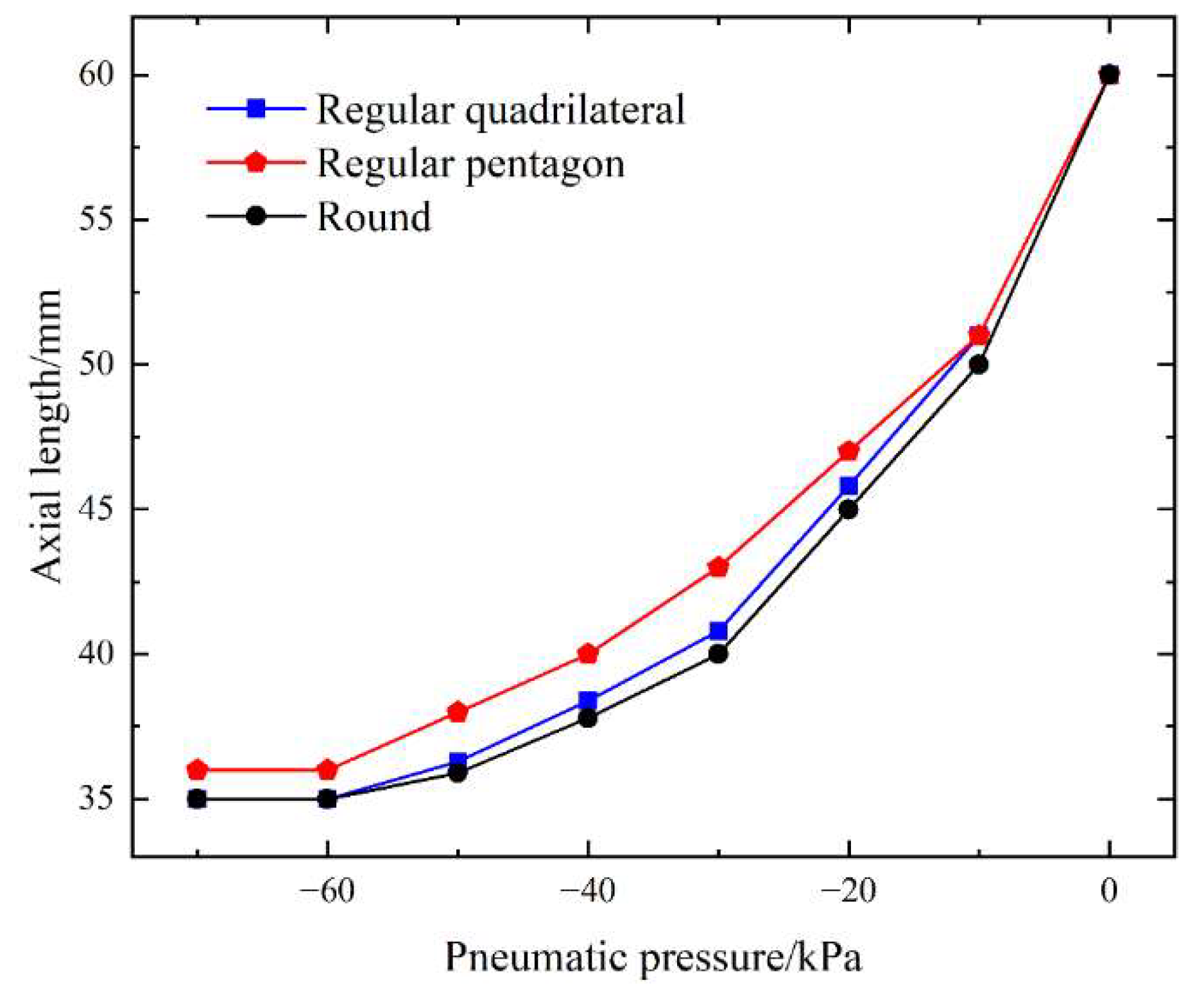
Figure 17.
Soft gripper gripping process diagram. (a) Initial state of the gripper, (b) The gripper moves to the vicinity of the target, (c) Gripper successfully grabs the target.
Figure 17.
Soft gripper gripping process diagram. (a) Initial state of the gripper, (b) The gripper moves to the vicinity of the target, (c) Gripper successfully grabs the target.
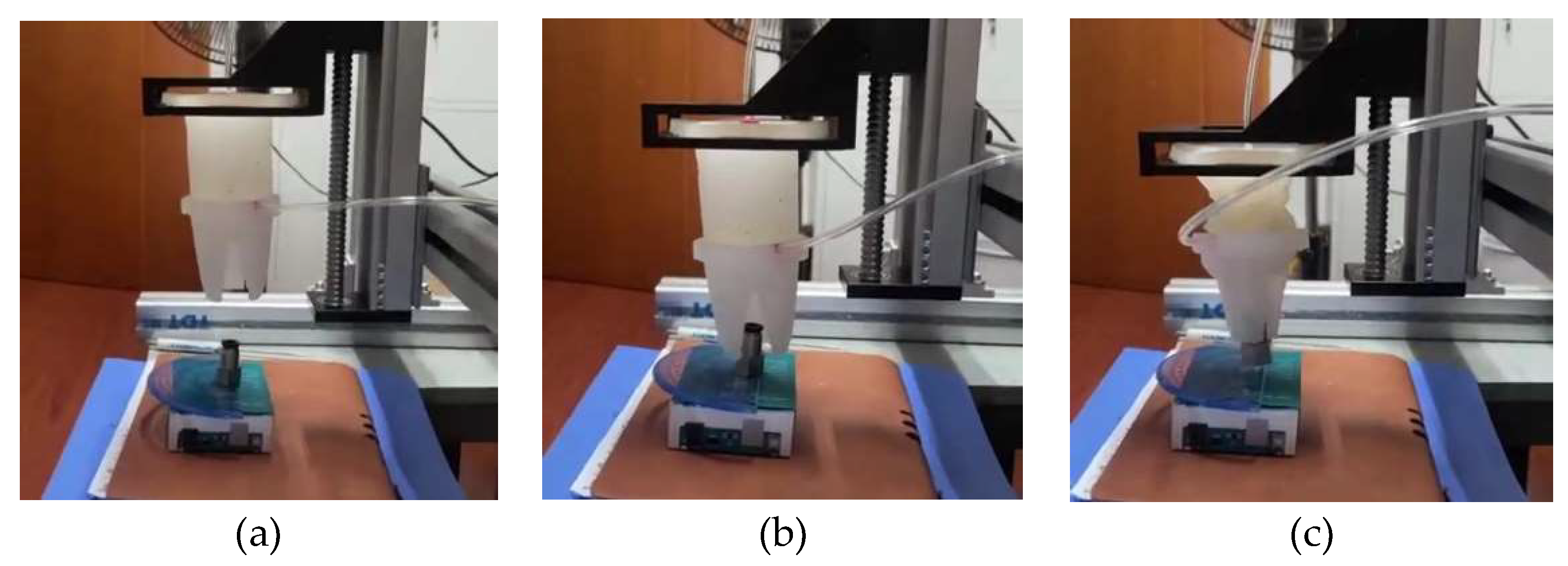
Figure 18.
Software gripper grasping test diagram. (a) USB flash drive, (b) circular industrial switch, (c) L-shaped Allen wrench, (d) quail egg.
Figure 18.
Software gripper grasping test diagram. (a) USB flash drive, (b) circular industrial switch, (c) L-shaped Allen wrench, (d) quail egg.
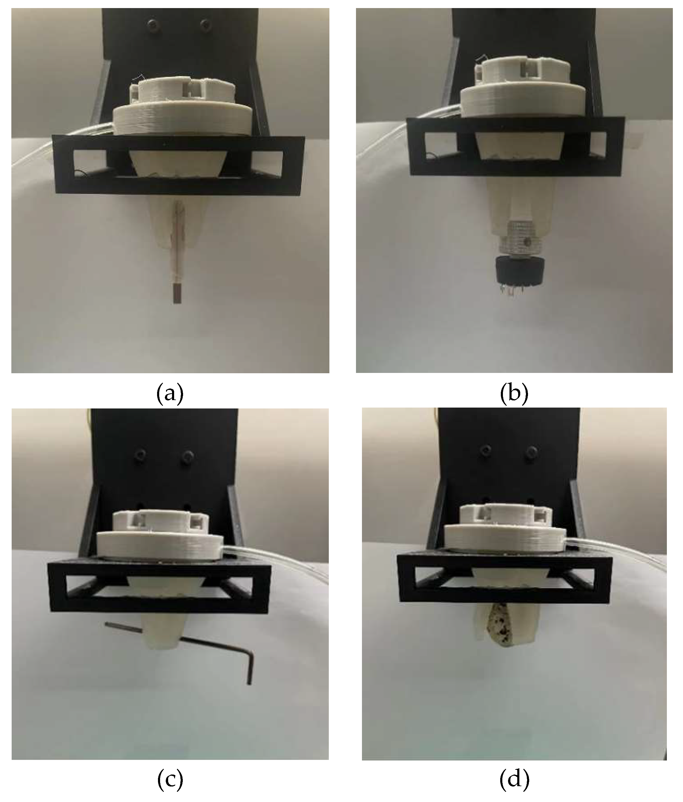
Figure 19.
The second modular combination experiment diagram.
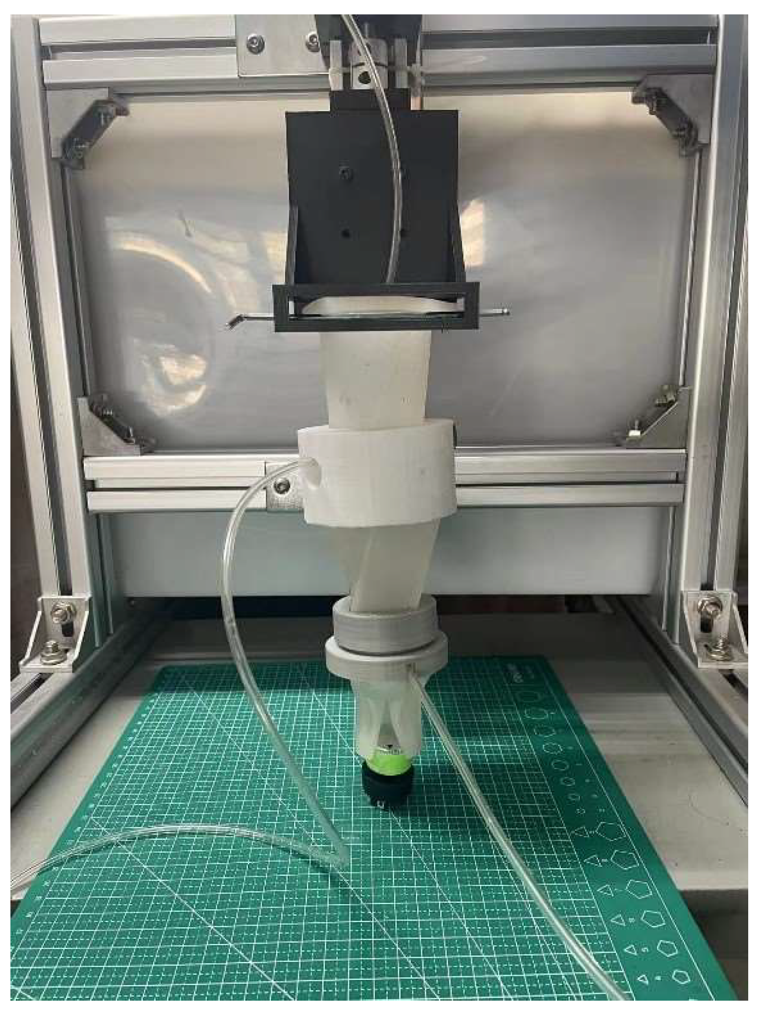
Figure 20.
Modular software gripper torsion process diagram. (a) Software gripper readiness, (b) Grab Actuator Negative Pressure Grab, (c) The negative pressure of actuator 1 is turned clockwise by 60°, (d) The negative pressure of actuator 2 is turned clockwise by 55°, (e) Actuator 2 deflates air and twists 55° counterclockwise, (f) The actuator deflates air and rotates 60° counterclockwise.
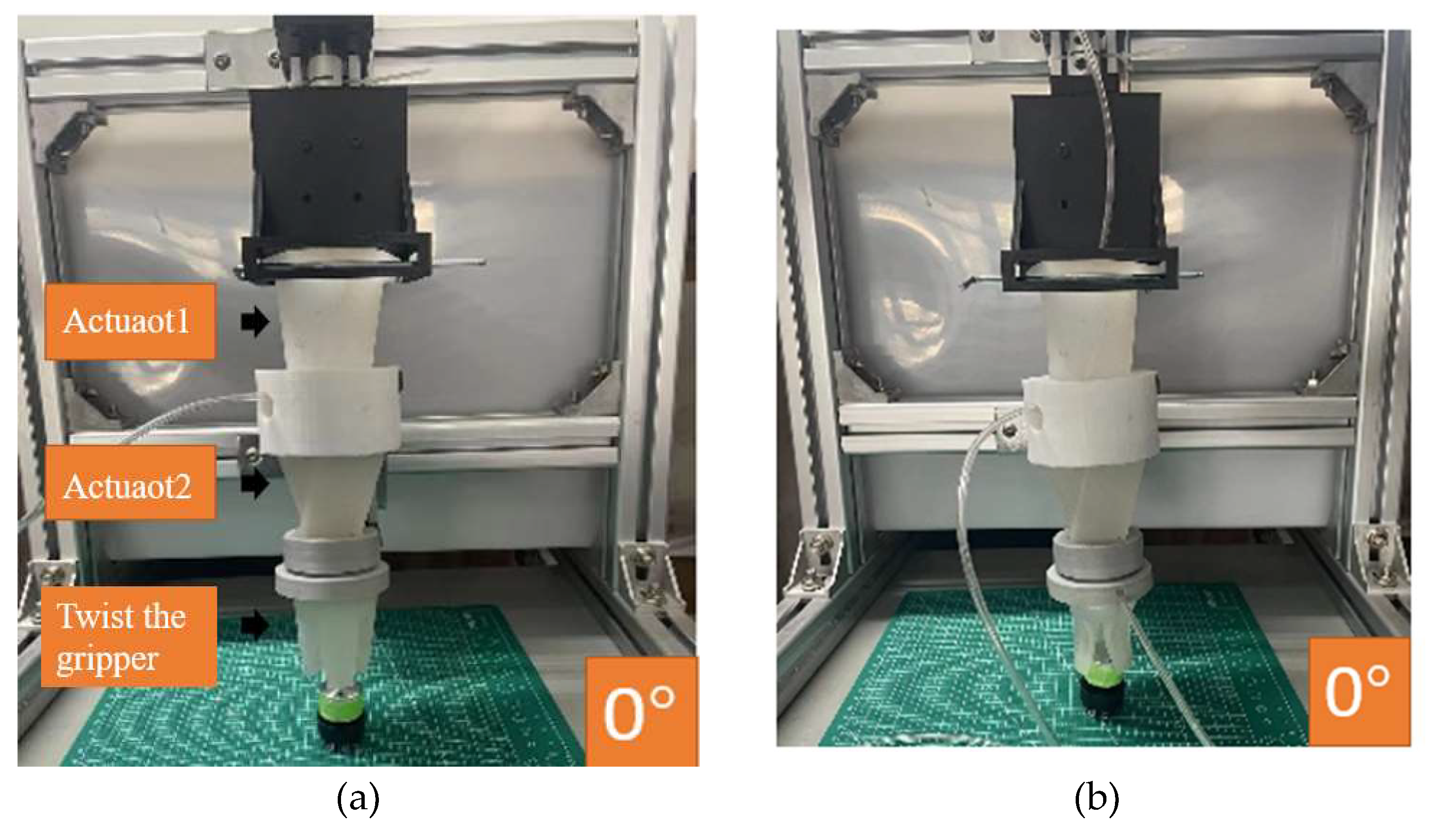
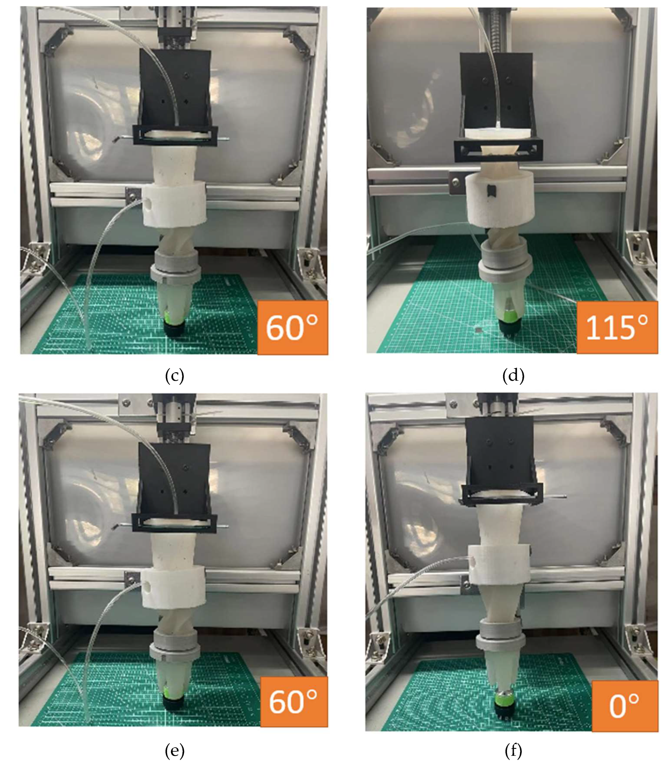
Figure 21.
Twisting grasp process diagram of modular software gripper. (a) Software gripper readiness, (b) Grab actuator negative pressure grab, (c) Actuator 1 is rotated clockwise, (d) Actuator 2 is rotated clockwise.
Figure 21.
Twisting grasp process diagram of modular software gripper. (a) Software gripper readiness, (b) Grab actuator negative pressure grab, (c) Actuator 1 is rotated clockwise, (d) Actuator 2 is rotated clockwise.
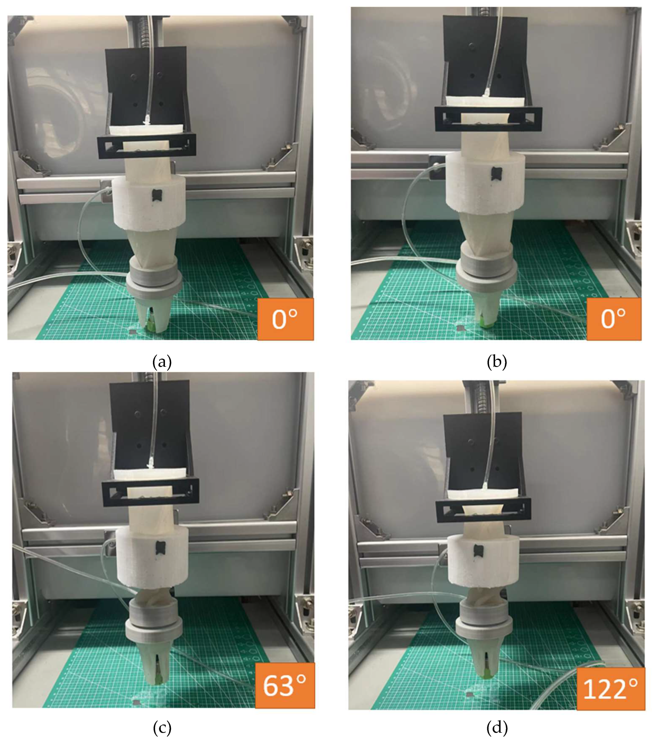
Table 1.
Specific material parameters for the Ecoflex series of silicone rubbers.
| Ecoflex series | 00-10 | 00-20 | 00-30 | 00-40 |
| Operable time | 40min | 30min | 45min | 18min |
| Curing time | 4h | 4h | 4h | 4h |
| Exercise elongation | 800% | 845% | 900% | 980% |
| Mixed viscosity | 14000 cps | 3000cps | 3000cps | 8000cps |
| Shore' s hardness | 00-10 | 00-20 | 00-30 | 00-40 |
| Tensile strength | 120psi | 160psi | 200psi | 315psi |
| Shrinkage ratio | <0.001% | <0.001% | <0.001% | <0.001% |
Table 2.
Lateral center thickness influence data sheet.
| Pressure | Twist angle of 2.5mm side thickness | Twist angle of 2mm side thickness | Twist angle of 1.5mm side thickness |
| 0kPa | 0° | 0° | 0° |
| 10kPa | 29° | 31° | 32° |
| 20kPa | 54° | 56° | 57° |
| 30kPa | 62° | 66° | 70° |
| 40kPa | 65° | 70° | 74° |
| 50kPa | 67° | 73° | 76° |
| 60kPa | 69° | 75° | 78° |
| 70kPa | 70° | 75° | 78° |
Table 3.
Test data of torsional actuator deformation angle with different side edge thickness parameters.
Table 3.
Test data of torsional actuator deformation angle with different side edge thickness parameters.
| Pressure | Twist angle of 3.5 mm thickness of side ribs | Twist angle of 3 mm thickness of side ribs | Twist angle of 2.5 mm thickness of side ribs | Twist angle of 2 mm thickness of side ribs |
| 0kPa | 0° | 0° | 0° | 0° |
| 10kPa | 27° | 29° | 32° | 34° |
| 20kPa | 52° | 54° | 57° | 59° |
| 30kPa | 60° | 64° | 70° | 72° |
| 40kPa | 65° | 70° | 74° | 75° |
| 50kPa | 67° | 73° | 76° | 77° |
| 60kPa | 69° | 74° | 78° | 78° |
| 70kPa | 70° | 74° | 78° | 78° |
Table 4.
Experimental torque data for torsional actuators with different base shapes.
| Air pressure | Positive quadrilateral actuator torque | Positive pentagonal actuator torque | Round actuator torque |
| 0kPa | 0N·m | 0N·m | 0N·m |
| -10kPa | 0.016N·m | 0.018N·m | 0.017N·m |
| -20kPa | 0.029N·m | 0.031N·m | 0.031N·m |
| -30kPa | 0.040N·m | 0.044N·m | 0.043N·m |
| -40kPa | 0.044N·m | 0.051N·m | 0.047N·m |
| -50kPa | 0.0477N·m | 0.055N·m | 0.0481N·m |
| -60kPa | 0.0479N·m | 0.057N·m | 0.0482N·m |
| -70kPa | 0.048N·m | 0.058N·m | 0.0485N·m |
Table 7.
Flow chart of the second modular combined control system.
 |
 |
Disclaimer/Publisher’s Note: The statements, opinions and data contained in all publications are solely those of the individual author(s) and contributor(s) and not of MDPI and/or the editor(s). MDPI and/or the editor(s) disclaim responsibility for any injury to people or property resulting from any ideas, methods, instructions or products referred to in the content. |
© 2023 by the authors. Licensee MDPI, Basel, Switzerland. This article is an open access article distributed under the terms and conditions of the Creative Commons Attribution (CC BY) license (http://creativecommons.org/licenses/by/4.0/).
Copyright: This open access article is published under a Creative Commons CC BY 4.0 license, which permit the free download, distribution, and reuse, provided that the author and preprint are cited in any reuse.


