
Submitted:
02 October 2025
Posted:
03 October 2025
You are already at the latest version
Abstract
Efficient heat transfer is crucial in modern electronics driven by the rise of artificial intelligence to maintain optimal system performance. In the last decades, scholars have explored various strategies to enhance electronic device thermal management, focusing on the effects of fin shape, dimension and spacing on heat transfer efficiency. Recent advancements in additive manufacturing have enabled fabrication of complex geometries, such as triply periodic minimal surfaces (TPMS), which offer promising alternatives to conventional designs. This study presents comparative analysis of thermal performance and fluid flow characteristics of two foam TPMS-based (gyroid and primitive) with foam wavy fin heat sinks made with the use of aluminum foam. COMSOL Multiphysics with implemented finite element method was used to simulate convective heat transfer, pressure drop, Nusselt number, and thermal performance at different fluid velocities along channel length. The foam structure was heated by copper plate, and the Nusselt number was evaluated over porosity levels from 0.1 to 0.9. Porosity between 0.5 and 0.7 offers the best balance of cooling performance and pumping power. Foam TPMS heat sinks, particularly gyroid structure, provide enhanced thermal dissipation owing to their high surface area-to-volume ratio and interconnected geometry. The finding confirms the potential of TPMS heat sinks as alternatives to conventional wavy designs for advanced thermal management applications.
Keywords:
heat sink
; TPMS
; porous structure
; fluid flow
; heat transfer
1. Introduction
Advancements in electronics, aerospace, automotive, and other industrial sectors demand compact and more efficient heat dissipation devices. Heat sink (HS) device dissipates heat from the source to the environment passively (naturally) or actively (using rotating elements such as fan and pumps) to regulate temperature and prevent overheating. The performance of electronic devices is directly limited by their ability to dissipate heat, and inadequate heat removal ultimately degrades performance, driving the development of more advanced HS [1]. Several factors, including vibration, humidity, temperature, and dust, contribute to electronic equipment failure. Thermal fatigue accounts for over 40% of device failure cases, making effective heat removal essential for long-term durability [2]. Researchers have investigated various mechanism to enhance heat transfer in heat sinks. In a conventional HS model, fin geometry, arrangements, spacing, and size strongly determine thermal performance [3,4,5,6]. Thermal performance of heat sink with rectangular, elliptical, cylindrical and plate fin geometry depends on flow condition and design constraints. Staggered fin arrangements, particularly for elliptical designs, outperform inline arrangements in heat transfer efficiency [7]. Perforated fins with cavities further improve performance than regular fins as the holes promote heat dissipation [2]. Fin spaces and its thickness has also significant influence on overall performance. Reduced fin spacing enhances efficiency in water-cooled minichannel heat sinks while thinner fins lower temperature rise [8,9]. Nevertheless, conventional heat sink design remain inadequate to meet the desired performance for the compactness and high thermal efficiency in advanced thermal systems.
For many years, cellular, lattice, foam and architectural materials and structures have been used in engineering [10], biomedicine [11], and other industries due to their lightweight, high-strength-to-weight ratio [12], and tunable mechanical and thermal properties. They have a wide range of applications, for example, energy absorption [13], thermal insulation or management [14,15], core in sandwich panels, as well as patients’ implants or prostheses [11]. Recently, Triply Periodic Minimal Surface (TPMS) structures have drawn much attention from researchers for Hs applications due to their significant thermophysical properties and compact design. The design of these structures has a high surface area to volume ratio, which is the basic requirement for thermal management. Such inherent qualities make TPMS structures highly effective in addressing challenges related to heat dissipation [9]. Triply periodic minimal surfaces (TPMS) are non-self-intersecting periodic implicit surfaces with a mean curvature of zero, meaning that the curvature along the principal plane is equal and opposite at every point, making the mean curvature zero. These surfaces are commonly found in natural structures, such as butterfly wings and weevil Lamprocyphus augustus [16,17]. TPMS lattices are classified into sheet and network based on their internal pore connectivity. Network lattice is continuous skeleton entire the volume, and sheet lattice is a continuous thin sheet that separate two distinct and interconnected porous regions [18]. Figure 1 illustrates different TPMS lattice configurations. The intricate internal channel of TPMS provides for an increased heat transfer area which leads to enhance heat transfer.
Several scholars investigated the effects of different TPMS design parameters on the overall heat transfer performance of heat sinks. Liu et al. (2025) [20] compared and reported fluid flow and heat transfer characteristics of traditional rectangular fin (RF) with TPMS lattice fabricated from AlSi10Mg alloys. The result revealed that TPMS lattice provide larger convective heat transfer area and more complex internal configuration which enhance the frictional resistance of the fluid and higher convective heat transfer coefficient under the same flow conditions. Numerical method was carried out to evaluate heat transfer and fluid flow characteristics of HS based on TPMS structures, including diamond-solid, gyroid-solid, and gyroid-sheet configurations, in natural free convection conditions [21]. Among the tested geometries, the gyroid-sheet configuration exhibited superior thermal efficiency when both the top and bottom surfaces were open. TPMS-based designs showed 35-50% improvement in performance compared to traditional pin-fin heat sinks. Attarzadeh et al. (2021) [16] presented in their work the contribution of TPMS thickness to determine the thermal efficiency of diamond-sheet structures. The result indicated that increasing the wall thickness initially boosted the convective heat transfer coefficient. However, exceedingly thick walls negatively impacted on the fluid flow, ultimately diminishing the overall thermal performance. Lattice cell size also another parameter determine fluid flow characteristics. The decrease in cell size from 10 mm to 6 mm increased the pressure drop across the diagonal cross-section by 63.1%, from 1.004 kPa to 1.632 kPa [22]. In Beer and Rybár paper [23] a comparative analysis of sheet, skeletal, and combined gyroid structures was conducted based on numerical simulations of fluid flow and heat transfer. Combined gyroid structure demonstrated the highest heat transfer efficiency, reflected in superior Nusselt numbers and Chilton–Colburn j-factors. A comparison of convective heat transfer enhancement of gyroid and diamond TPMS structures was conducted using the deform control parameter (β), varying from 0.1 to 0.75, based on numerical and experimental analysis. The result reveals that increasing β values also increases convective heat transfer coefficient both in gyroid and diamond but more increment is observed in the gyroid structure [24]. Convective properties of TPMS are sometimes incorporated with recursive or fractal structural characteristics [25]. The result of study shows a significant reduction in flow resistance for TPMS with first-order fractal characteristics when compared to the original TPMS structure. However, second-order fractal characteristics led to a substantial increase in flow resistance. Tang et al. [26] introduced TPMS-with-fin-structures (TFS-gyroid), showing that adding fins to gyroid TPMS enhances convective heat transfer by 27–34% while the pressure drop from inlet to outlet increased up to six times higher depending on fin height. Subsequently, Al-Ketan et al. [27] discovered that increasing wall thickness along the flow direction in TPMS structures simultaneously decreases both convective heat transfer coefficient and channel resistance.
This paper aims to evaluate the fluid flow and heat transfer characteristics of two foam TPMS structures (gyroid and primitive) and a traditional wavy fin in a heat sink using numerical methods. All structures were built from aluminium foam material with porosity range 0.1 to 0.9. Finite element analysis was used to solve governing equations with boundary conditions. The foam structure was heated by a copper plate, and the Nusselt number was evaluated over porosity levels. Porosity between 0.5 and 0.7 offers the best balance of cooling performance and pumping power. The heat sinks with foam TPMS structure, particularly, gyroid structure, provide enhanced thermal dissipation owing to their high surface area-to-volume ratio and interconnected geometry. The results confirm the potential of foam TPMS heat sinks as alternatives to conventional wavy designs for advanced thermal management applications.
Heat sinks are typically made of aluminium or copper and have fins, pins or other elements that increase the surface area of the component to improve and accelerate heat transfer to the surrounding environment (e.g. fluid or air). Usually, these elements are made of solid material, most often it is metal with high thermal conductivity. The main novelty of this paper is analysis of thermal performance of heat sink with foam TPMS and foam conventional wavy structures. For comparison, two TPMS structures (gyroid and primitive) and wavy fin conventional heat sink geometries were selected. All structures (TPMS and wavy) were built from aluminium foam material with porosity range from 0.1 to 0.9. Finite element analysis was used to solve governing equations with boundary conditions. It is shown that the porosity of the structure influences the thermal properties of the heat sink.
The paper consists of four chapters. The first presents an introduction and state-of-the-art. Second is devoted to materials and methods, mathematical equations of TPMS lattices geometries, geometric modelling, governing equations with boundary conditions and influence of mesh elements on computation results. The third chapter explain numerical results and discussion. The last chapter presents conclusions achieved in the computational analysis.
2. Materials and Methods
2.1. Mathematical Equations of TPMS Lattices
Triply periodic minimal surface (TPMS) is a minimal surface that extends periodically in three spatial directions and is designed using mathematical algorithms based on an implicit function. The level set equations are type of mathematical equations that describe a three-dimensional surface. This surface is defined by a trigonometric function, ϕ(x,y,z), where all points (x,y,z) on the surface satisfy the condition ϕ(x,y,z) = c. Where c is a constant called the level set value. Some of the common TPMS equations were described in Equations (1-4), which are found in the literature [17]:
where α, β and γ denote constants related to the unit cell size (L) in x, y and z respectively; c is the offset parameter. Sheet structure has nearly zero offset parameter while network TPMS structure has ϕ(x,y,z) ≥ C or ϕ(x,y,z) ≤ C. Figure 2 shows two solid TPMS lattice (gyroid and primitive) and solid wavy fin structures. As we can see from the figures, lattice structures have complex geometry and are not easily manufactured in every CAD tool. In the current work, 3D geometries of TPMS are generated using MSLattice software [28]. The material for the considered structures (Figure 2) is aluminum foam with various porosities (from 0.1 to 0.9).
As illustrated in Table 1, among HS structures with identical lattice thickness, gyroid lattice exhibits the highest surface-to-volume ratio, while the wavy structure has the lowest. In modelling of various lattice geometries, decreasing the unit length of a lattice causes its surface-to-volume ratio to increase linearly [29].
2.2. Geometric Modelling and Boundary Conditions
The full geometry of model contains fluid channel, uniform heat source from the bottom and three different heat sink geometries (gyroid, primitive and wavy – see Figure 2). The dimensions of all heat sink structures are 15 x 15 x 30 [mm3] with thickness of 2.5 [mm]. In order to allow the fluid to become fully developed at both inlet and outlet, 15 [mm] extension section is added to end structures. Additionally, cylindrical shapes are incorporated at both ends of the fluid channel model. To simplify the heat performance comparison between the TPMS and the traditional wavy fin heat sink, we considered that the heat transfer area of the fin structure closely matches that of the gyroid lattice. The edges of channels filleted to reduce pressure loss during analysis. The copper plate heat source size of 30 x 15 x 6 [mm3] is modelled at the bottom of fluid domain. Figure 3 illustrates 3D model of heat sink and the set of boundary conditions.
In the current study, the heat transfer medium (water) with constant inlet velocity, and inlet temperature, Tin flows into heat sink structure, and the copper plate from bottom generates heat uniformly at constant power, P = 36 Watts. Induced heat is transferred to shell and heat sink structures through conduction, then it dissipates to the environment via convection through the outlet region [30]. The outlet boundary is pressure outlet, . The outer walls of the channels were considered as adiabatic with a no-slip condition in order to neglect the effects of heat transfer from the lateral boundaries. The others boundary conditions for heat transfer are insulation, and for fluid flow in non-slip. The detail boundary conditions for inlet and outlet are presented in Table 2. Excellent thermal conductivity materials such as copper (heat plate) and aluminium (heat sink structure) were used to enhance overall heat dissipation. Table 3 presents detailed fluid and thermal properties of heat sink materials [31].
2.3. Governing Equations
A three-dimensional multiphysics stationary problem built in COMSOL V5.1 was selected to evaluate the heat transfer and fluid flow characteristics of gyroid, primitive TPMS, and wavy fin heat sink structures. Firstly, the simulation domain, created in MSLattice and saved in STL format, was imported into COMSOL and subsequently repaired. Computational fluid dynamics (CFD) simulations have been utilised to analyse the structural and fluid flow behaviour of heat sinks. In the analysis, some necessary assumptions were adopted: (1) the fluid passing through the channel is Newtonian, incompressible and steady state; (2) no heat generation occurs inside the porous/foam medium; (3) local thermal equilibrium between the fluid and the solid phase of metal foam.
Considering the above assumptions, COMSOL Multiphysics uses the following built-in governing equations to compute heat transfer between the fluid and solid domains.
Fluid flow is governed by the Navier-Stokes equations:
where: is fluid velocity vector, density of fluid [kg/m3], dynamic viscosity [Pa·s].
The Brinkman equation was used to describe the fluid flow through a porous/foam medium in the channel [25,32]:
where: is the porosity of the aluminum foam matrix, K is permeability of aluminum foam, is the dynamic viscosity of water, represents the Forchheimer coefficient and is the buoyancy term.
Heat transfer in a solid is governed by the equations:
The energy equation was also used to explain heat transfer inside the foam and solid, and it is defined by:
The effective thermal conductivity of the porous/foam medium filled with fluid can be described by the porosity () and thermal conductivity of the solid phase () and fluid phase () using the following equation [33]:
In the current study, hydraulic parameters of the TPMS structures were analyzed using the Reynolds number, friction factor, and pressure drop. Reynolds number was derived by [1,20]:
where, is the fluid density, is the hydraulic diameter of porous structure, u is the characteristic fluid velocity, is the viscosity of fluid and is porosity. Hydraulic diameter, , for TPMS structures was determined by [34]:
where represents void volume and is the wetted surface area of the structure.
The heat transfer efficiency of the TPMS structure evaluated through convective heat transfer coefficient () and the Nusselt number (Nu). Convective heat transfer coefficient indicates the rate at which heat is transferred by convection compared to conduction within the fluid and it calculated by [35]:
where q’’ is heat flux applied at the bottom of the copper plate and it is obtained from heat generated (36 Watts) per cross-sectional area (15 [mm] x 30 [mm]) giving 8 W/cm2. The logmean temperature difference, also determined by [34]:
The local Nusselt number () characterizes intensity of heat transfer from a fluid to a solid boundary and it estimated by equation [36]:
where, k is the thermal conductivity of water. The Darcy friction factor, f, and another dimensionless parameter, defined as [37]:
where , L and u are pressure loss between inlet and outlet, length of TPMS structure and inlet velocity, respectively. The overall performance evaluation criterion (PEC) was determined by combination of dimensionless f and . It is presented in next equation:
2.4. Meshing Independence Methods
Mesh independence check was performed using COMSOL Multiphysics, and it incorporates specific meshing strategies such as corner refinement, free tetrahedral elements, and boundary layers. Unstructured free tetrahedral used to discrete complex TPMS structure while hexahedral meshing type used for rectangular box of heat source. Three computational meshing domains (hot plate, heat sink and fluid domain are explained in Figure 4. Mesh is denser within internal TPMS structure compared to the outer surface and it helps to capture the complex flow and heat transfer phenomena. Mesh convergence testing (grid independence study) was conducted to validate the accuracy of the computed flow and thermal fields. Table 4 details average Nusselt number () computational results at different mesh sizes. The optimum Nuavg obtained at finer mesh size with domain elements of 504487 which is used in temperature, velocity and pressure calculations.
3. Results and Discussion
3.1. Fluid Flow Characteristics
Figure 5 represents the velocity map of heat transfer medium within lattice (gyroid and primitive) and traditional wavy fin models. From the figure we can identify that the complex contour surfaces of model strongly influence flow characteristics. The length of cross section are transversely taken with dimensions in millimeters of 5, 15, 25, 35, 45, 55 and 65 in the direction of fluid flow. The results indicated that, in comparison to wavy structure and primitive structure, gyroid TPMS displays a distinct flow pattern, with slightly higher flow velocity (0.0977 [m/s]) distributed non-uniformly within the channel. In the gyroid lattice, turbulent flow characteristics and a high surface area were observed, leading to high heat transfer. In primitive TPMS, high velocity is concentrated near channel center (37.5 [mm]), while a wavy flow is distributed uniformly along the parallel path. The less effective heat transfer is observed in the conventional heat sink (wavy fin) compared to TPMS heat sink.
Figure 6 illustrates streamlines velocity and temperature distribution profile for different heat sink models. In case of velocity profile, the most striking feature of gyroid structure is the highly intricate and tortuous flow paths. Within this lattice, the streamlines characterized by twists, turns, and interconnected passages distributed throughout the entire volume of the heat sink. Despite complex paths, the uniformly streamlines filled in the channels, help for effective fluid distribution and maximized heat transfer area (Figure 6a).
The primitive lattice exhibits streamlines that are denser around its primitive cells. This configuration results in less tortuous flow paths and a consequently lower pressure drop when compared to the gyroid structure (Figure 6 (b)). Smooth and less convoluted parallel path of wavy lower the pressure drop compared to the gyroid and primitive lattice (Figure 6 (c)). Variation in temperature distribution is visible in different heat sink geometries as shown in Figure 6 (d), (e) and (f). At the initial region of inner structure, the heat source from bottom plate caused a rapid increase in temperature. Eventually, the temperature reached its peak and slightly began to decline beyond the end of structure. Among these models, the max temperature of 377 [K] was obtained from wavy-type heat sink. Primitive shows intermediate temperatures between the Wavy and gyroid model that performs better heat dissipation than Wavy structure. The gyroid structure consistently maintains the lowest temperature, thereby facilitating more efficient heat transfer away from the heat sources.
3.2. Effects of Porosity on the Temperature Distribution Across the Channel Length
The graph shown in Figure 7 represents the temperature profile along a line passing through the center of heat sink channel length for the porosity range 0.3 to 0.9 and constant permeability 1e-8 [m2]. The shape of temperature plot along the channel length are wave due to intricate geometry of gyroid heat sink. From the plot we understand that an increase in porosity value results in a higher fluid volume fraction and a reduced solid fraction within the TPMS structure, which weakens its ability to conduct heat away from the hotspot. Therefore, the foam structure thermally less effective and the temperature distribution along the channel become rises. A maximum temperature of 298 [K] is obtained from a foam material having a porosity value of 0.3 from the result of simulations. As noted, the minimum temperature along the channel length was observed for the highest porosity of the heat sink structure (porosity equal to 0.9, see Figure 7).
3.3. Logmean Temperature Difference (LMTD) in the Heat Sink
Figure 8 illustrates fluid flow velocity vs logmean temperature difference, between the inlet and outlet boundaries of the heat sink. During the fluid velocity increases, the convective heat transfer coefficient rises and the heat sink surface become cooled more effectively. This reduces the temperature gradient between heat sink and fluid, resulting in faster heat dissipation from heat sink. The finding reveals that the primitive heat sink design achieves a lower LMTD than both gyroid and wavy structures.
Figure 9 presents the heated temperature distribution along the line passes through the center of channel under different heat fluxes, 4 [W/cm2], 6 [W/cm2], 8 [W/cm2], 10 [W/cm2 ] and 12 [W/cm2] with 0.05 [m/s] inlet water fluid velocity at constant porosity of 0.9 and permeability 1e-8 [m2] The temperature in the gyroid lattice structure is increased in the fluid flow direction which indicates the heat generated by copper block transferred into the working fluid quickly due to high heat transfer performance of foam TPMS heat sink availability. The simulation results show that the maximum temperature of 302 [K] at a heat flux of 12 [W/cm²]occurs around the end edge of the heat source (23.5 [mm]). It indicates that an increase in the heat source from the bottom plate leads to an increase in the temperature distribution.
3.4. Pressure Gradient in Different HS Geometries
Comparison of pressure drop per unit length for gyroid, primitive and wavy configuration were presented in Figure 10. The suggested pressure gradient increases as the fluid velocity increases. This results from higher flow velocities leads to greater frictional losses and thus larger pressure gradient. Among the three structures, the gyroid architecture appears to be the most advantageous in minimizing pressure drop at a given fluid velocity.
3.5. Local Nusselt Number Distribution Along Channel Length
Figure 11 illustrates a comparison of the Nusselt number for the gyroid, primitive and wavy fin model at different porosity from 0.1 to 0.9. In all cases, the Nusselt number slightly declines along the channel length. It is evident from this result that, at lower porosities, enhanced surface area promotes higher Nusselt numbers and flow resistance is high, which can limit fluid penetration, while at higher porosities, reduced solid fraction lowers heat transfer. This is because the surface area decreases with increasing porosity. The best porosity range is typically 0.5 to 0.7 for the TPMS heat sink, where cooling performance and pumping power (hydraulic performance) are balanced.
Nusselt number variations are strongly influenced by the heat sink geometry. In Figure 12, the effects of three different heat sink geometries on Nusselt number are compared under conditions of 0.9 porosity and 1 × 10⁻⁸ [m²] permeability. In all models, the Nusselt number decreases with increasing channel length, due to the developed thermal resistance which leads to reduce the local heat transfer coefficient. These results clearly indicated that Gyroid structure exhibit the highest Nusselt number compared to primitive and wavy fin geometries. The complex and interconnected network gyroid structure creates a highly tortuous flow path, promoting greater fluid mixing and the most effective for heat removal.
4. Conclusions
Triply Periodic Minimal Surface (TPMS) structures draw much attention from researchers for HS applications. The advantage of these structures lies in their compact design and significant thermophysical properties. In the current paper, heat transfer performance and flow characteristics of two TPMS structures (gyroid and primitive) evaluated with a conventional wavy fin heat sink using numerical methods. The design of this structure has high surface area to volume ratio, which is the basic requirement for thermal management. Water is the fluid medium used in the analysis, and aluminium acts as the material of foam TPMS structure. The following conclusions are drawn from the findings of the research.
- 1)
- The average Nusselt number of the gyroid, primitive and wavy heat sink model decreases along the channel length due to the rising local temperature.
- 2)
- A TPMS heat sink with 0.7 porosity exhibits balanced hydraulic and better cooling performance in the heat sink analysis.
- 3)
- The temperature of TPMS increased in the fluid flow direction as the heat flux from the bottom plate increased from 4 [W/cm2] to 12 [W/cm2].
- 4)
- For the similar inlet parameters i.e. porosity, permeability, inlet velocity and inlet temperature, the gyroid HS model exhibits the highest Nusselt number compared to primitive and wavy structures. This promotes high fluid mixing and effective heat removal. This research summarised potential TPMS lattice in electronic thermal management, but further study is required to address challenges with thermal performance.
Author Contributions
Conceptualization, T.S.; methodology, W.I. and T.S.; software, W.I. and T.S.; computation and validation, W.I. and T.S.; formal analysis, W.I. and T.S.; investigation, W.I. and T.S.; resources, T.S; writing—original draft preparation, W.I. and T.S.; writing—review and editing, W.I. and T.S.; visualization, W.I.; supervision, T.S.; project administration, T.S.; funding acquisition, W.I. and T.S. All authors have read and agreed to the published version of the manuscript.
Funding
This work has been supported by a grant from the Ministry of Science and Higher Education in Poland: 0612/SBAD/3640 (2025-2026). The simulations were made at the Institute of Applied Mechanics (Poznan University of Technology).
Institutional Review Board Statement
Not applicable.
Informed Consent Statement
Not applicable.
Data Availability Statement
The original contributions presented in this study are included in the article. Further inquiries can be directed to the corresponding authors.
Conflicts of Interest
The authors declare no conflicts of interest.
References
- Tang, W.; Zhou, H.; Zeng, Y.; Yan, M.; Jiang, C.; Yang, P.; et al. Analysis on the convective heat transfer process and performance evaluation of Triply Periodic Minimal Surface (TPMS) based on Diamond, Gyroid and Iwp. Int J Heat Mass Transf. 2023, 201, 123642. [Google Scholar] [CrossRef]
- Gaikwad, A.; Sathe, A.; Sanap, S. A design approach for thermal enhancement in heat sinks using different types of fins: A review. Front Therm Eng. 2023, 2, 980985. [Google Scholar] [CrossRef]
- Behnia, M.; Copeland, D.; Soodphakdee, D. A comparison of heat sink geometries for laminar forced convection: Numerical simulation of periodically developed flow. In IEEE. 1998; 310–315. [Google Scholar] [CrossRef]
- Wang, Q.; Tao, J.; Cui, Z.; Zhang, T.; Chen, G. Numerical simulation of fluid and heat transfer characteristics of microchannel heat sink with fan-shaped grooves and triangular truncated ribs. Int Commun Heat Mass Transf. 2024, 155, 107580. [Google Scholar] [CrossRef]
- Zohora, FT.; Haque, MR.; Haque, MM. Numerical investigation of the hydrothermal performance of novel pin-fin heat sinks with hyperbolic, wavy, and crinkle geometries and various perforations. Int. J. Therm. Sci. 2023, 194, 108578. [Google Scholar] [CrossRef]
- Manisa, IW.; Abhishek, SS. Analysis of Fins with Varying Shapes for their thermal behavior in heat sink: A Review. Int J Adv Eng Manag IJAEM. 2022, 4, 1267–79. [Google Scholar] [CrossRef]
- Soodphakdee, D.; Behnia, M.; Copeland, DW. A comparison of fin geometries for heatsinks in laminar forced convection: Part I-round, elliptical, and plate fins in staggered and in-line configurations. Int J Microcircuits Electron Packag. 2001, 24, 68–76. [Google Scholar]
- Jajja, SA.; Ali, W.; Ali, HM.; Ali, AM. Water cooled minichannel heat sinks for microprocessor cooling: Effect of fin spacing. Appl Therm Eng. 2014, 64, 76–82. [Google Scholar] [CrossRef]
- Yaseen, SJ. Numerical study of the fluid flow and heat transfer in a finned heat sink using Ansys Icepak. Open Eng. 2023, 13, 20220440. [Google Scholar] [CrossRef]
- Mrozek, A.; Strek, T. Numerical Analysis of Dynamic Properties of an Auxetic Structure with Rotating Squares with Holes. Materials. 2022, 15, 8712. [Google Scholar] [CrossRef]
- Mrozek-Czajkowska, A.; Stręk, T. Design Optimization of the Mechanics of a Metamaterial-Based Prosthetic Foot. Materials. 2024, 18, 96. [Google Scholar] [CrossRef] [PubMed]
- Han, D.; Ren, X.; Zhang, Y.; Zhang, X.Y.; Zhang, X.G.; Luo, C.; Xie, Y.M. Lightweight auxetic metamaterials: Design and characteristic study. Compos. Struct. 2022, 293, 115706. [Google Scholar] [CrossRef]
- Novak, N.; Vesenjak, M.; Kennedy, G.; Thadhani, N.; Ren, Z. Response of Chiral Auxetic Composite Sandwich Panel to Fragment Simulating Projectile Impact. Phys. Status Solidi. 2019, 257, 1900099. [Google Scholar] [CrossRef]
- Burlaga, B.; Kroma, A.; Poszwa, P.; Kłosowiak, P.; Popielarski, P.; Stręk, T. Heat Transfer Analysis of 3D Printed Wax Injection Mold Used in Investment Casting. Materials. 2022, 15, 6545. [Google Scholar] [CrossRef]
- Grima-Cornish, J.N.; Attard, D.; Grima, J.N.; Evans, K.E. Auxetic Behavior and Other Negative Thermomechanical Properties from Rotating Rigid Units. Phys. Status Solidi RRL. 2022, 16, 2100322. [Google Scholar] [CrossRef]
- Attarzadeh, R.; Rovira, M.; Duwig, C. Design analysis of the “Schwartz D” based heat exchanger: A numerical study. Int J Heat Mass Transf. 2021, 177, 121415. [Google Scholar] [CrossRef]
- Yeranee, K.; Rao, Y. A review of recent investigations on flow and heat transfer enhancement in cooling channels embedded with triply periodic minimal surfaces (TPMS). Energies 2022, 15, 8994. [Google Scholar] [CrossRef]
- Singh, A.; Al-Ketan, O.; Karathanasopoulos, N. Mechanical performance of solid and sheet network-based stochastic interpenetrating phase composite materials. Compos Part B Eng. 2023, 251, 110478. [Google Scholar] [CrossRef]
- Liu, J.; Cheng, D.; Oo, K.; McCrimmon, TL.; Bai, S. Design and Additive Manufacturing of TPMS Heat Exchangers. Appl Sci. 2024, 14, 3970. [Google Scholar] [CrossRef]
- Liu, Z.; Gao, Z.; Dai, M.; Song, B.; Yang, B.; Zhang, T.; et al. Fluid Flow and Heat Transfer Performances of Aluminum Alloy Lattices with Triply Periodic Minimal Surfaces. Materials. 2025, 18, 1407. [Google Scholar] [CrossRef]
- Baobaid, N.; Ali, MI.; Khan, KA.; Al-Rub, RKA. Fluid flow and heat transfer of porous TPMS architected heat sinks in free convection environment. Case Stud Therm Eng. 2022, 33, 101944. [Google Scholar] [CrossRef]
- Oh, SH.; Kim, JE.; Jang, CH.; Kim, J.; Park, CY.; Park, K. Multifunctional gradations of TPMS architected heat exchanger for enhancements in flow and heat exchange performances. Sci Rep. 2025, 15, 19931. [Google Scholar] [CrossRef] [PubMed]
- Beer, M.; Rybár, R. Numerical Study of Fluid Flow in a Gyroid-Shaped Heat Transfer Element. Energies. 2024, 17, 2244. [Google Scholar] [CrossRef]
- Barakat, A.; Sun, B. Controlling TPMS lattice deformation for enhanced convective heat transfer: A comparative study of Diamond and Gyroid structures. Int Commun Heat Mass Transf. 2024, 154, 107443. [Google Scholar] [CrossRef]
- Beer, M.; Rybár, R. Optimisation of Heat Exchanger Performance Using Modified Gyroid-Based TPMS Structures. Processes. 2024, 12, 2943. [Google Scholar] [CrossRef]
- Tang, W.; Guo, J.; Yang, F.; Zeng, L.; Wang, X.; Liu, W.; et al. Performance analysis and optimization of the Gyroid-type triply periodic minimal surface heat sink incorporated with fin structures. Appl Therm Eng. 2024, 255, 123950. [Google Scholar] [CrossRef]
- Al-Ketan, O.; Ali, M.; Khalil, M.; Rowshan, R.; Khan, K.A.; Abu, Al-Rub RK. Forced convection computational fluid dynamics analysis of architected and three-dimensional printable heat sinks based on triply periodic minimal surfaces. J Therm Sci Eng Appl. 2021; 13, 021010. [Google Scholar] [CrossRef]
- Al-Ketan O; Abu Al-Rub RK. MSLattice: A free software for generating uniform and graded lattices based on triply periodic minimal surfaces. Mat Design Process Comm. 2021, 3, e205. [CrossRef]
- Dutkowski, K.; Kruzel, M.; Rokosz, K. Review of the state-of-the-art uses of minimal surfaces in heat transfer. Energies. 2022, 15, 7994. [Google Scholar] [CrossRef]
- Lin, L.; Zhao, J.; Lu, G.; Wang, XD.; Yan, WM. Heat transfer enhancement in microchannel heat sink by wavy channel with changing wavelength/amplitude. Int J Therm Sci. 2017, 118, 423–34. [Google Scholar] [CrossRef]
- Small, E.; Sadeghipour, SM.; Asheghi, M. Heat sinks with enhanced heat transfer capability for electronic cooling applications. J. Electron. Packag. 2006. [CrossRef]
- Bayomy, AM.; Saghir, Z. Thermal performance of finned aluminum heat sink filled with ERG aluminum foam: Experimental and numerical approach. Int J Energy Res. 2020, 44, 4411–25. [Google Scholar] [CrossRef]
- Bayomy, A.; Saghir, M. Experimental and Numerical Study of the Heat Transfer Characteristics of Aluminium Metal Foam (with/without channels) Subjected to Steady Water Flow. Pertanika J Sci Technol. 2017, 25. [Google Scholar]
- Barakat, A.; Pan, Y.; Sun, B. Comparative Heat Transfer Performance of TPMS Structures: Spotlight on Fisch Koch S versus Gyroid, Diamond and SplitP Lattices. EDP Sciences, 2024; 01009. [Google Scholar] [CrossRef]
- Arshad, A.; Saeed, M.; Ikhlaq, M.; Imran, M.; Yan, Y. Heat and fluid flow analysis of micro-porous heat sink for electronics cooling: Effect of porosities and pore densities. Therm Sci Eng Prog. 2025, 57, 103129. [Google Scholar] [CrossRef]
- Zhang, Y.; Peng, F.; Jia, H.; Zhao, Z.; Wang, P.; Duan, S.; et al. Conformal geometric design and additive manufacturing for special-shaped TPMS heat exchangers. Int J Heat Mass Transf. 2025, 247, 127146. [Google Scholar] [CrossRef]
- Saghir, MZ.; Rahman, MM. Effectiveness in Cooling a Heat Sink in the Presence of a TPMS Porous Structure Comparing Two Different Flow Directions. Fluids. 2024, 9, 297. [Google Scholar] [CrossRef]
Figure 1.
Types of TPMS lattice structure: (a) gyroid (b) neovius (c) diamond (d) Schwarz [19].
Figure 1.
Types of TPMS lattice structure: (a) gyroid (b) neovius (c) diamond (d) Schwarz [19].
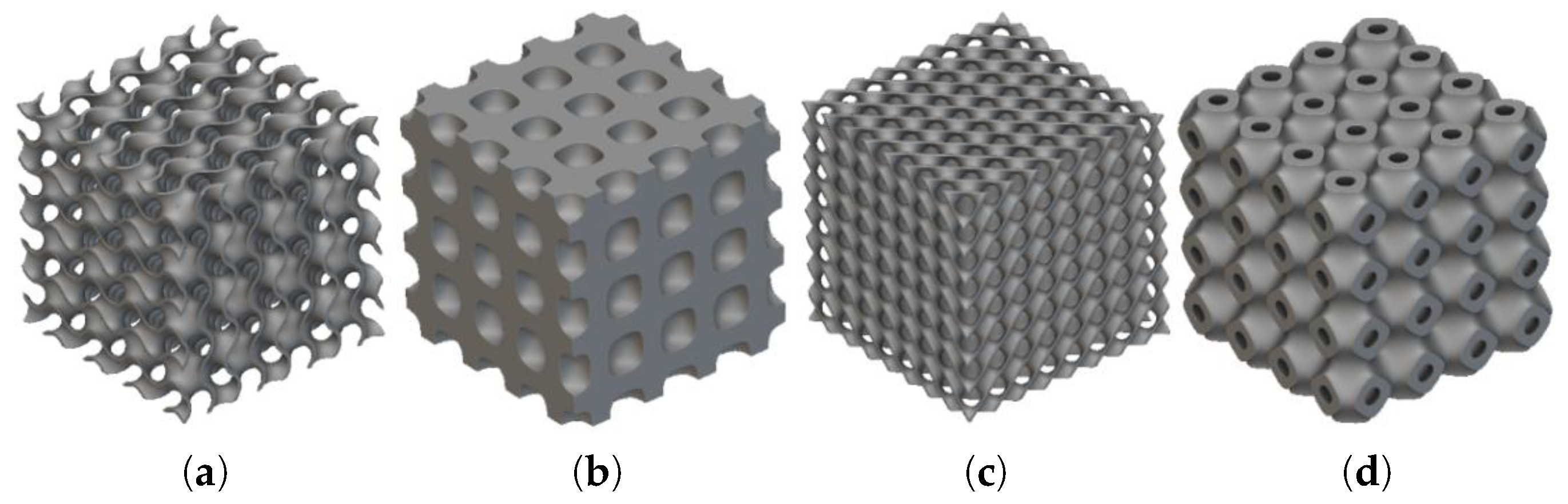
Figure 2.
Three dimensional model of heat sink structures: (a) gyroid, (b) primitive, and (c) wavy.
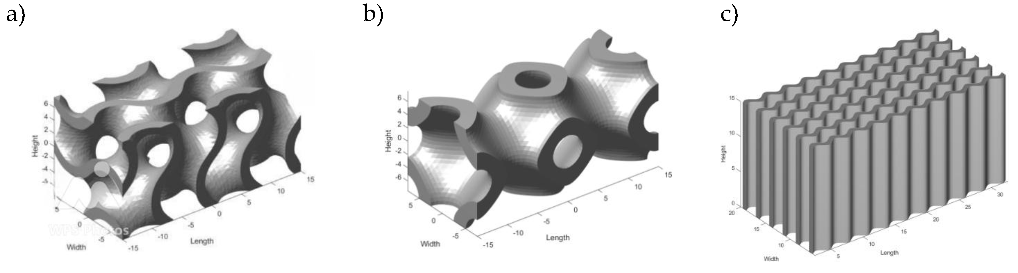
Figure 3.
Simulation domains and boundary conditions.
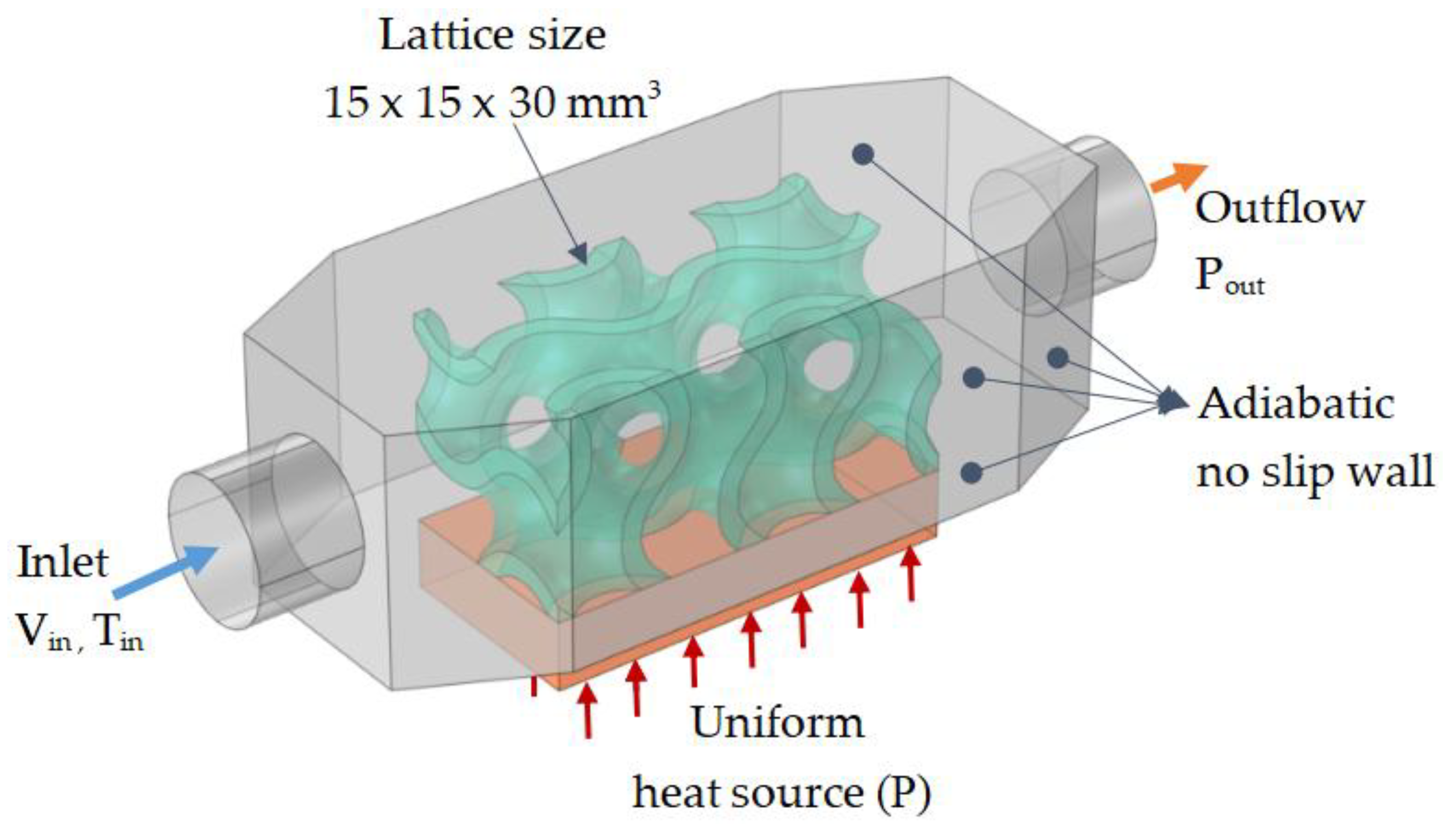
Figure 4.
Three dimensional a) model and b) meshes of heat sink domains.
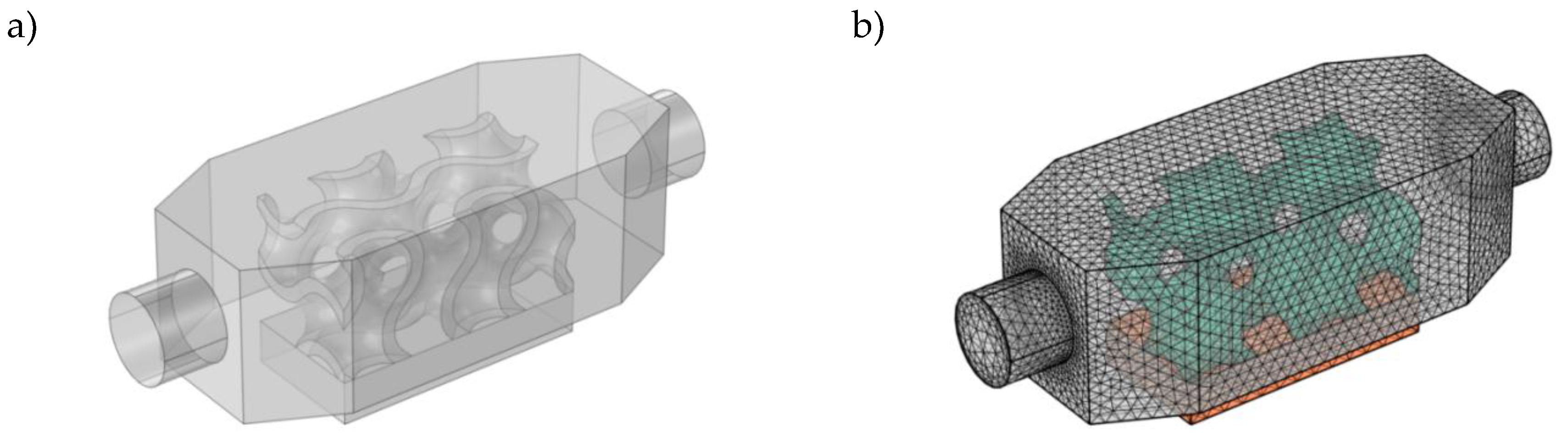
Figure 5.
Flow field distribution profile: (a) gyroid (b) primitive and (c) wavy.
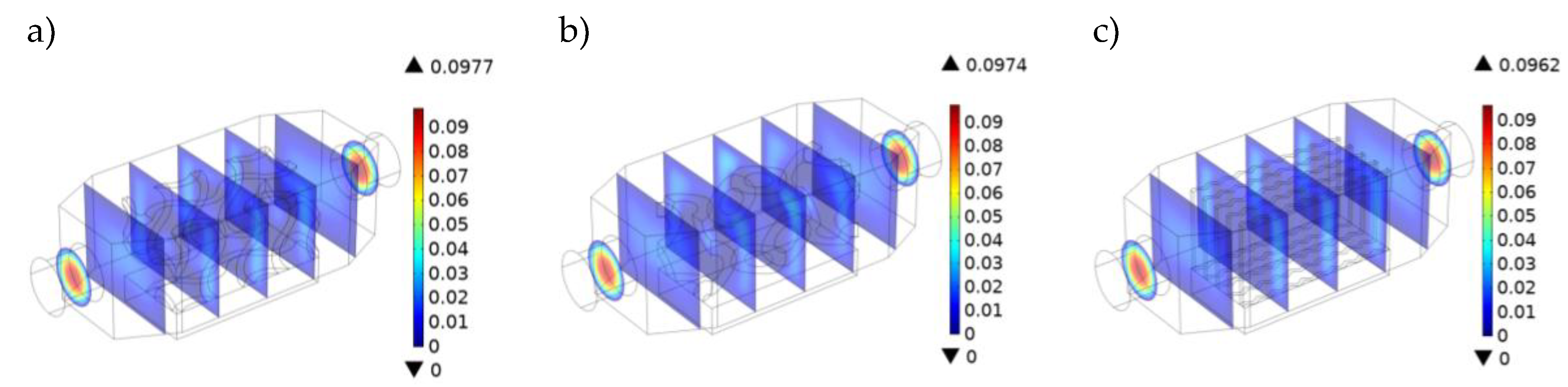
Figure 6.
Streamlines velocity profile and temperature distribution for different HS geometries: (a) velocity profile – gyroid, (b) velocity profile – primitive, (c) velocity profile – wavy, (d) temperature profile – gyroid, (e) temperature profile – primitive, and (f) temperature profile – wavy.
Figure 6.
Streamlines velocity profile and temperature distribution for different HS geometries: (a) velocity profile – gyroid, (b) velocity profile – primitive, (c) velocity profile – wavy, (d) temperature profile – gyroid, (e) temperature profile – primitive, and (f) temperature profile – wavy.
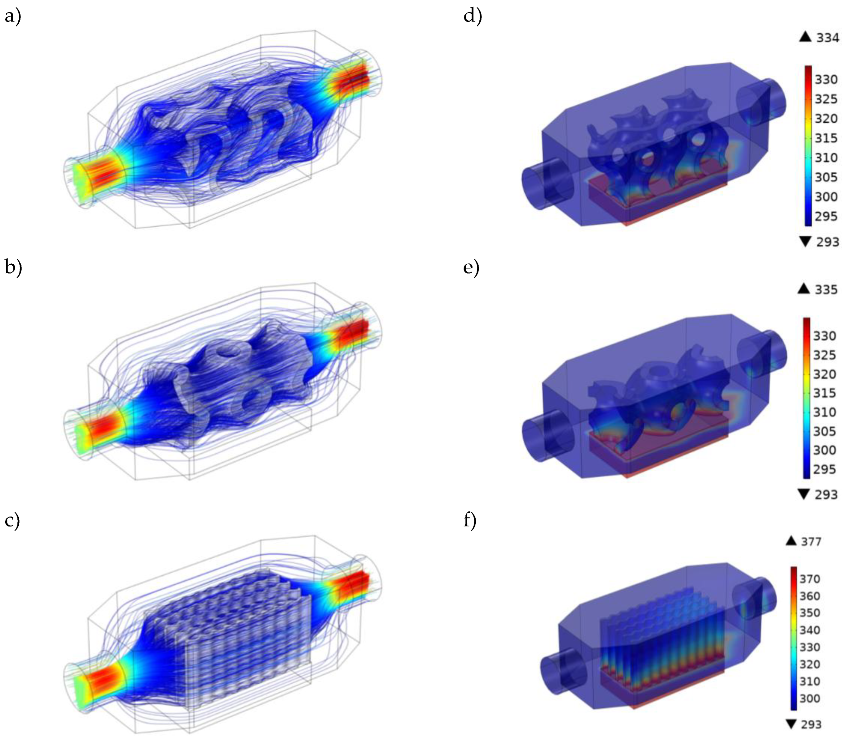
Figure 7.
The effect of porosity on the temperature profile along the channel length.
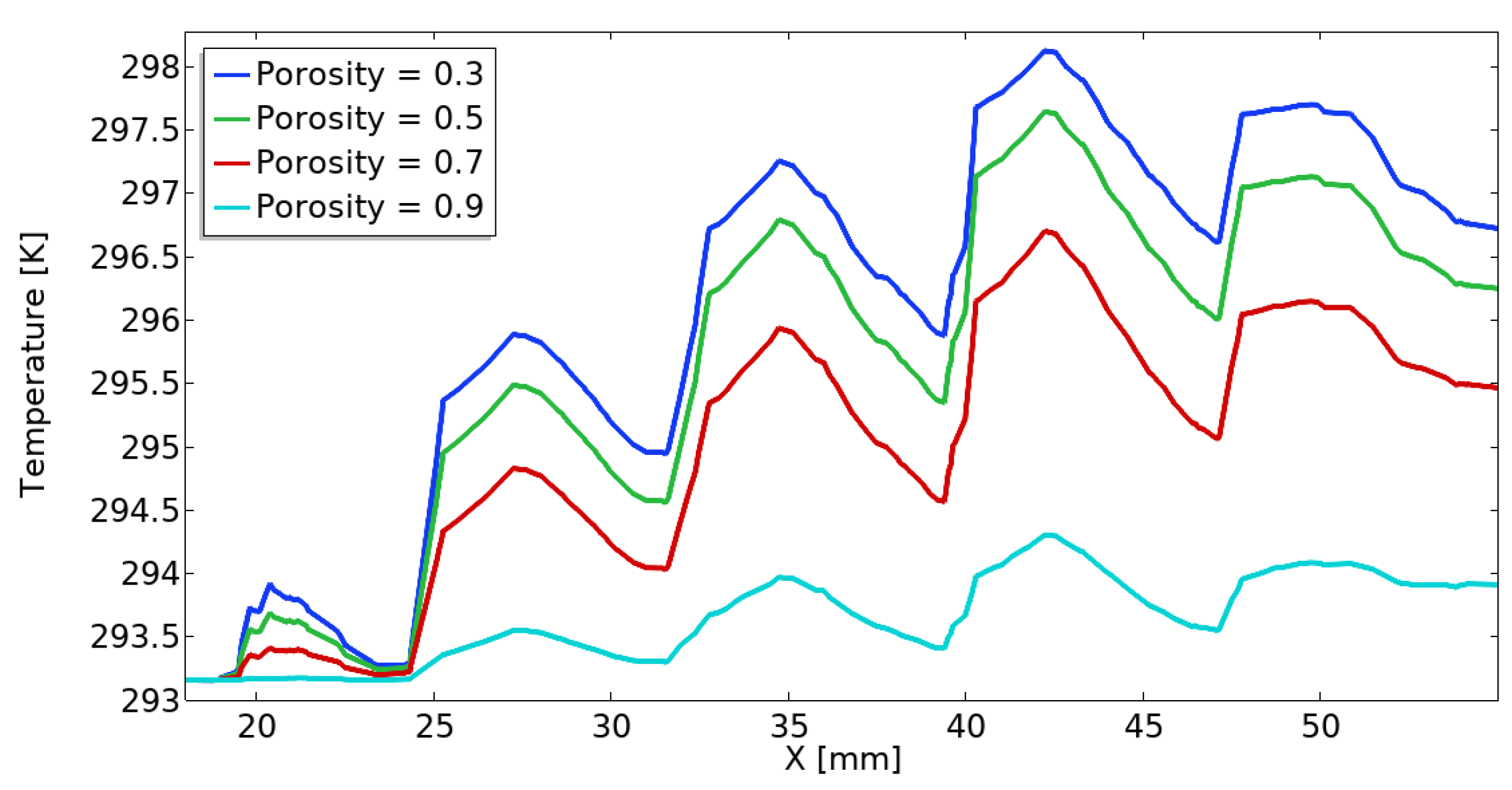
Figure 8.
Logmean temperature difference vs flow velocities.
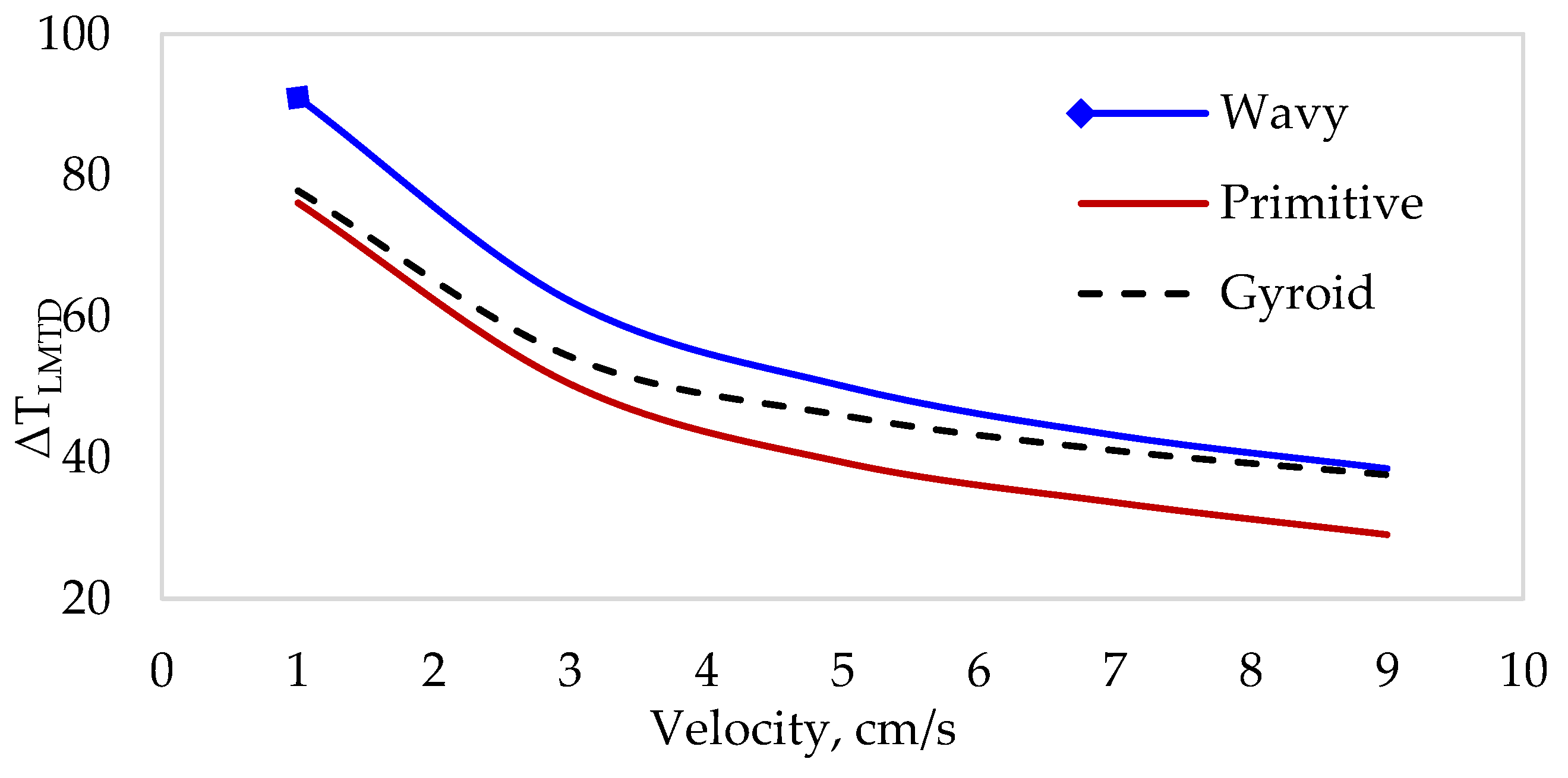
Figure 9.
Heat flux effect on the temperature profile along channel length.
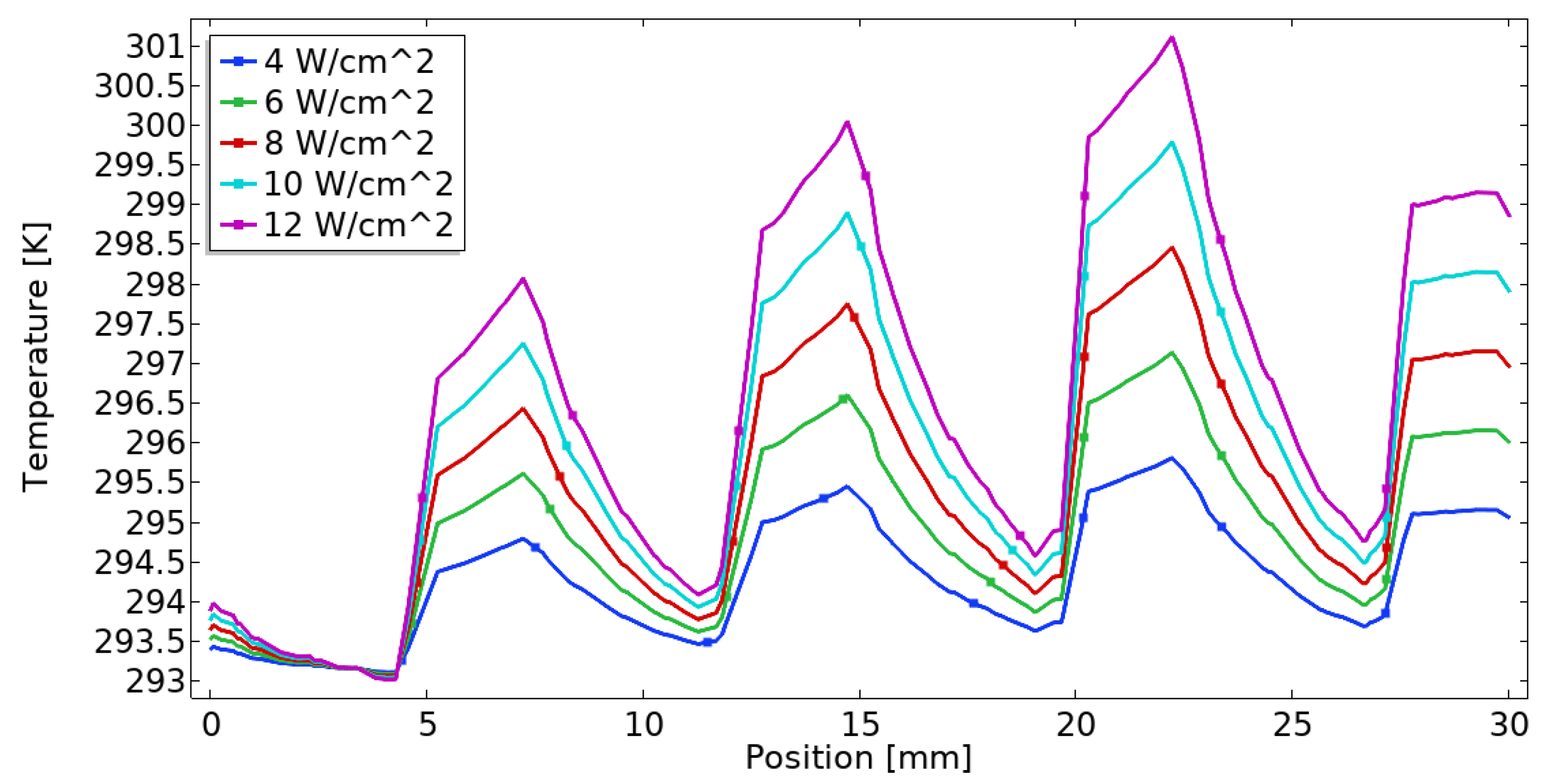
Figure 10.
Pressure gradient vs fluid flow velocity.
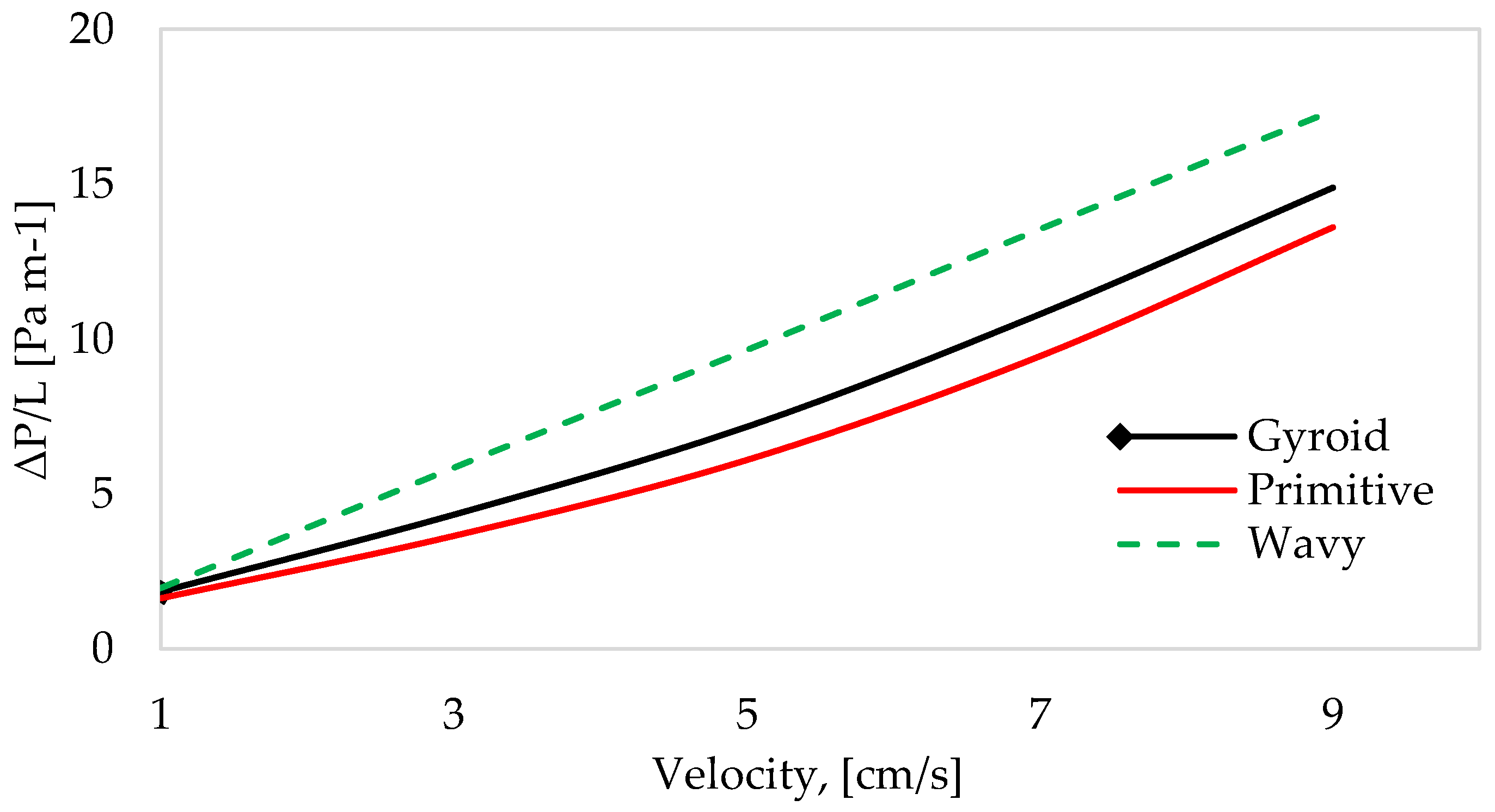
Figure 11.
Influence of porosity on Nusselt number along the channel section.
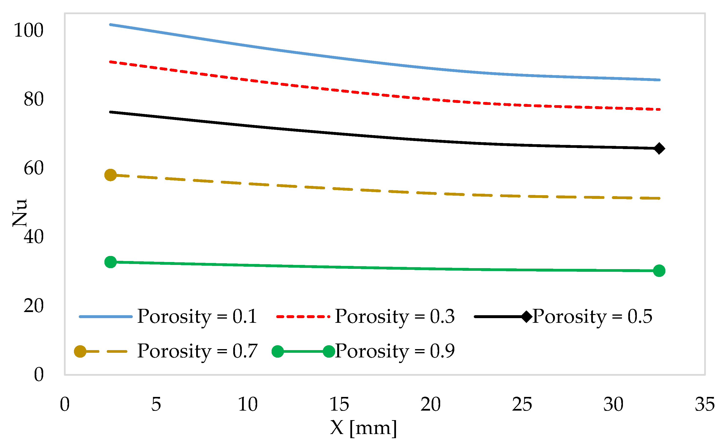
Figure 12.
Profile of Nusselt number along the channel.
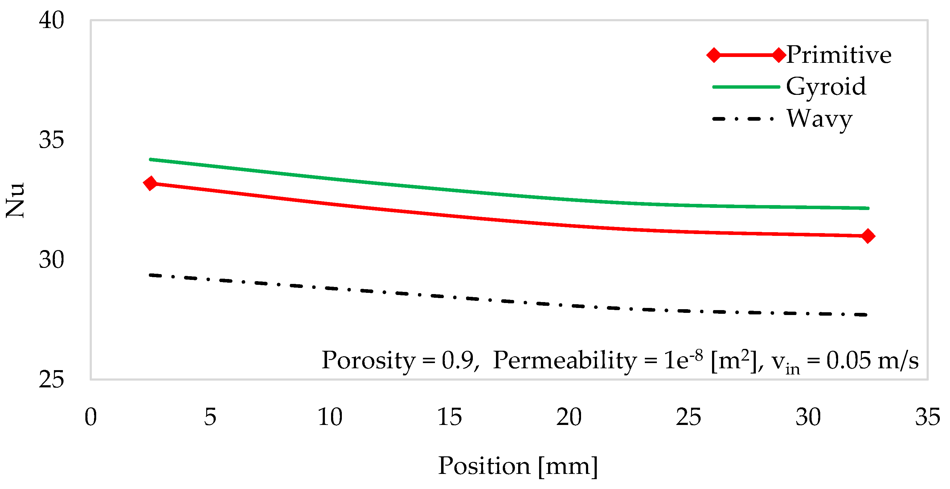

Table 1.
Geometric characteristics of various heat sink structures.
| Type | SA | SA to V ratio | Lattice length, [mm] |
|---|---|---|---|
| Primitive | 4288 | 2.32 | 15 x 15 x 30 |
| Gyroid | 5183 | 2.82 | |
| Wavy fin | 9496 | 1.86 |
Table 2.
Boundary conditions for inlet and outlet.
| Boundary | Temperature | Velocity | Pressure |
|---|---|---|---|
| Inlet | Tin = 293.15 [K] |
|
- |
| Outlet | - | - | . |
Table 3.
Fluid and thermal properties of materials.
| Materials | Thermal conductivity [W/(m K)] | Density [kg/m3] | Specific heat capacity [J/(kg K)] | Dynamic viscosity [kg/(m s)] |
|---|---|---|---|---|
| Copper | 400 | 8960 | 385 | - |
| Aluminium | 238 | 2700 | 900 | - |
| Water | 0.6 | 997 | 4182 | 0.89e-03 |
Table 4.
Mesh sensitivity analysis for average Nusselt number.
| Mesh size | Domain elements | Boundary elements |
Edge elements |
Average Nusselt number |
|---|---|---|---|---|
| Extra coarser | 20866 | 4813 | 693 | 52.3 |
| Coarser | 27225 | 5901 | 786 | 54.9 |
| Normal | 114512 | 14175 | 1228 | 60.9 |
| Fine | 195069 | 21295 | 1532 | 61.7 |
| Finer | 504487 | 39930 | 2101 | 63.4 |
Disclaimer/Publisher’s Note: The statements, opinions and data contained in all publications are solely those of the individual author(s) and contributor(s) and not of MDPI and/or the editor(s). MDPI and/or the editor(s) disclaim responsibility for any injury to people or property resulting from any ideas, methods, instructions or products referred to in the content. |
© 2025 by the authors. Licensee MDPI, Basel, Switzerland. This article is an open access article distributed under the terms and conditions of the Creative Commons Attribution (CC BY) license (http://creativecommons.org/licenses/by/4.0/).
Copyright: This open access article is published under a Creative Commons CC BY 4.0 license, which permit the free download, distribution, and reuse, provided that the author and preprint are cited in any reuse.


