
Submitted:
06 August 2025
Posted:
08 August 2025
You are already at the latest version
Abstract
This study presents a detailed numerical analysis of a three-dimensional micro pin fin heat sink incorporating 55 fins arranged in a single channel in four distinct cross-sectional geometries: square, circular, triangular, and pentagonal. A conventional microchannel heat sink (MCHS) without pin fins serves as a baseline for comparison. Water is employed as the working fluid, and simulations are conducted over a laminar flow regime with Reynolds numbers ranging from 500 to 1500. To efficiently capture the thermo-hydrodynamic behavior and reduce computational cost, a representative single flow channel is simulated under symmetrical boundary conditions, and key pin fin parameters such as height and spacing are systematically varied. The cross-sectional hydraulic diameter and spacing are held constant for all cases, with step sizes and non-dimensional spacing ratios sp/hp adjusted to assess their effect on heat sink performance. Results indicate that among all geometries, circular fins exhibit the highest heat transfer enhancement, with the Nusselt number increasing by 60% at Re = 500 and by 90% at Re = 1500 compared to the baseline. However, this improved thermal performance is accompanied by a greater pressure drop relative to the other tested pin fin shapes. Following the circular fins, triangular and square configurations offer progressively lower heat transfer rates, while pentagonal pin fins demonstrate the minimum enhancement. Furthermore, for all fin geometries, increasing the Reynolds number leads to a consistent improvement in heat transfer. Overall, the study provides quantitative insights into the impact of pin fin geometry and arrangement on the thermal and fluid dynamic performance of micro pin fin heat sinks, offering valuable guidelines for the design of advanced cooling solutions in microelectronics.
Keywords:
microchannel heat sink (MCHS)
; micro pin fin array
; thermal efficiency
; Nusselt number
; pressure drop
; heat transfer
; circular fins
; square fins
; triangular fins
; pentagonal fins
; hydraulic diameter
; pin fin design
; fin shape variation
1. Introduction
Mini and microchannel heat exchangers have garnered significant attention lately due to their compact size and high efficiency, making them ideal for various cutting-edge thermal management applications. These encompass not only the cooling of electronic components and microelectromechanical systems (MEMS), but also more intricate systems, including cooling procedures for nuclear reactors, high-performance computing units, and aerospace components. The global research effort has increased due to the need for more effective and compact thermal solutions. Numerous studies in our country that concentrate on the numerical simulation of microchannel flows demonstrate this interest [1,2,3,4]. To better understand heat transfer properties and fluid flow behaviour under various conditions, these studies investigate a range of channel designs, dimensions, and thermal barrier conditions [1].
A wide range of contemporary engineering systems now rely heavily on miniature heat exchangers, particularly those functioning at the mini and micro scales. Their small size and high heat transfer efficiency make them ideal for various applications, including fuel cell systems, air conditioners, heat pumps, gas turbines, and thermal control in electronic devices [2,3,4]. Although these systems are technologically advanced and have strong potential, their widespread integration remains largely confined to industrial sectors. Many domestic industries possess the technological and financial capabilities to purchase and implement these cutting-edge thermal management solutions. However, a significant portion of the technology is still imported due to a lack of local production and development. This dependency, combined with high initial costs and a lack of consumer-level awareness, has restricted the adoption of miniature and micro heat exchanger systems in the broader consumer market.
Many sophisticated engineering applications, especially the design of microscale heat exchangers and microchannel heat sinks (MCHS) for thermal management in microelectronic systems, are based on studying fluid dynamics and heat transfer within microchannels. Due to their advantageous features, including small size, low environmental impact, and affordability, MCHSs have garnered significant attention as highly effective thermal dissipation solutions since the groundbreaking research by Tuckerman and Pease [5]. A considerable amount of research has been conducted to investigate the impact of various design and operational parameters on the thermohydraulic behaviour of these systems, to enhance cooling performance. The channels’ diameters and cross-sectional configurations [6,7,8,9,10], their arrangement and pattern [7,8,9,10], the choice of working fluids and their thermophysical characteristics [11,12,13,14,15,16,17,18,19,20,21,22], and the features of solid–fluid interfaces [23,24,25,26,27] are some of these aspects. The goal of these studies is to maximise MCHSs’ overall performance in terms of pressure drop control and heat transfer efficiency. The cross-sectional geometry of microchannels plays a crucial role in determining the thermal and fluid flow performance of microchannel heat sinks (MCHS). Recent advances leverage principles from self-similar tree-like branching networks to further optimize fluid distribution, minimize hydraulic loss, and enhance thermal performance in microchannel systems, providing a generalizable framework that extends beyond conventional straight or parallel channel designs for both circular and rectangular channels with working fluid of power-law and yield stress rheologies as well as for smooth and roughened channel walls [28,29,30,31]. In addition, insights from continuum modeling of deformable nanochannels highlight how flexible, biomimetic conduits can achieve superior transport and adaptive thermal regulation at the micro- and nano-scale [32,33].
Gunnasegaran et al. [2] analysed the behaviour of water flow and convective heat transfer in microchannels with rectangular, trapezoidal, and triangular profiles. Their study revealed that, within each cross-sectional type, reducing the hydraulic diameter leads to a higher convective heat transfer coefficient, accompanied by an increase in pressure drop. Furthermore, the triangular microchannel showed the lowest heat transfer coefficient among the geometries under study, whereas the rectangular microchannel showed the greatest.
To investigate the fluid flow and convective heat transfer behaviour in microchannel heat sinks (MCHS) with rectangular, trapezoidal, and triangular cross-sectional shapes, Wang et al. [34] performed numerical simulations while keeping the channel cross-sectional area constant for comparison. According to their findings, the trapezoidal and triangular microchannels performed the best at dissipating heat, while the rectangular microchannel had the lowest thermal resistance. Chen et al. [35] conducted a similar investigation employing the same fin geometries as used in the studies by Wang et al. [34] and Gunnasegaran et al. [2] According to their research, microchannels with a triangular shape had the maximum thermal efficiency, while those with a rectangular shape had the lowest, illustrating the impact of flow conditions and evaluation criteria on performance results.
The primary cause of the contradictory findings in earlier research is that the majority of them only looked at particular microchannel sizes rather than a broad variety of dimensions. Comprehensive studies comparing the hydraulic and thermal performance of various microchannel forms under uniform size constraints are still lacking. Establishing a precise guideline or rule that can identify the cross-sectional shape that provides the best overall performance in terms of fluid flow and heat transfer would be highly beneficial. The hydraulic and thermal performance of microchannel heat sinks (MCHS) with different cross-sectional geometries is assessed numerically in this work. Four geometries, circular, square, pentagon, and triangular are chosen for examination because of their simplicity of production and widespread use in the structure of existing research. Microchannel size limits are used to provide a consistent evaluation under regulated dimensional limitations and to guarantee a fair and relevant comparison of performance across these various shapes. With this method, the fluid flow and heat transfer properties of microchannel heat sinks (MCHS) with four different cross-sectional geometries are methodically examined and contrasted in the current work. The main goal is to develop a trustworthy standard or selection criterion for determining which microchannel shape, among circular, square, pentagon, and triangle profiles, is most effective in terms of thermal management and hydraulic performance. Through a better knowledge of how cross-sectional geometry affects overall system efficiency, this study seeks to support the optimal design of MCHS.
Despite numerous comparative studies, there is a lack of unified understanding regarding how fin geometry affects overall thermal performance under identical dimensions and boundary conditions. This study numerically investigates and compares four fin geometries across multiple aspect ratios and Reynolds numbers, aiming to identify optimal configurations for enhanced heat transfer and minimal pressure drop.
2. Problem Description
The study investigates a 3D micro pin fin heat sink with 55 fins in four geometric shapes: square, circular, triangular, and pentagonal as shown in Figure 1. A traditional microchannel heat sink (MCHS) without pins was used as a baseline to evaluate thermal performance and flow behavior. To reduce computational cost and time, only a single flow channel of the MCHS was analyzed. The pin cross-section, including hydraulic diameter and spacing , was kept constant, while the pin height was varied. To extend the scope of comparison and analyze the effect of the non-dimensional spacing ratio / on MCHS thermal efficiency, pin step sizes of 60, 55, 50, 45, 40, and 35 m were used, corresponding to / ratios of 0.250, 0.272, 0.300, 0.330, 0.375, and 0.428. A total of 55 heat sink models were chosen based on the performance of the heat sink; standard MCHS designs without pin fins were numerically evaluated. Simulations were carried out at seven different Reynolds numbers between 500 and 1500, all within the laminar flow range. The base dimensions for both setups were = 600 m and = 265 m, giving a bottom surface area of 55 mm2. The non-dimensional aspect ratio of the pin fin is given by = /, where is the diameter and is the height of the fin. Table 1 shows the key geometric characteristics used in the computational domain. The simulation considers a computational zone consisting of a single row of solid structures surrounded by the working fluid. Symmetrical boundary conditions were used to save computational burden. Table 2 shows the physical properties of the coolant and heat sink.
2.1. Mathematical Modelling
A commercial multi-physics simulation program, ANSYS Fluent 19.2, was used to examine the thermal performance and flow characteristics of mini and micro heat sinks. Laminar flow in horizontal channels was the main focus of a single-phase, steady-state 3D solid-fluid conjugate heat transfer technique. Gravitational effects were disregarded, and fluid properties were assumed to be constant. Under the following presumptions, the conjugate heat transfer between the solid and fluid regions was investigated.
- A liquid is a Newtonian-incompressible fluid.
- All aspects of the system, including flow and heat transfer, are in a condition of steady state.
- Natural convection, heat radiation, gravitational force, and viscous dissipation are among the forces and losses that are not taken into account.
The governing equations are represented by the following mathematical equations:
Continuity equation:
Momentum equation:
Energy equation for liquid:
Energy equation for solid:
Here, u stands for the fluid velocity vector, p for hydrostatic pressure, and , , , , and for the liquid and solid’s density, dynamic viscosity, specific heat capacity, and thermal conductivity, respectively.
Deionised water was utilised as the coolant, while copper was chosen as the material for the heat sink. Boundary conditions for pressure and mass flow rate, respectively, determined the heat sink’s input and outflow. Assuming negligible surface resistance, a no-slip condition was implemented at the wall-fluid interface. To reach microchannel flow velocities () of 0.5, 0.7, 0.8, 1.0, 1.2, 1.35, and 1.5 m/s—corresponding to Reynolds numbers of 500, 700, 800, 1000, 1200, 1350, and 1500—the mass flow rates were adjusted. The output pressure was held at 0 Pascal (gauge), while the inlet fluid temperature was fixed at 300 K. The bottom surface of the channel received a consistent heat flux of 100 W/m2.
2.2. Data Reduction
Hydraulic diameter () is determined using the following formula
and are the height and width of the channel. The following formula is used to calculate the Reynolds number
In this equation, V denotes the mean velocity, represents the hydraulic diameter, and refers to the dynamic viscosity of the fluid. The heat transfer coefficient is calculated using the following formula
Here, Q represents the heat flux, while and refer to the temperatures of the wall and the fluid, respectively. The Nusselt number is calculated using the heat transfer coefficient as follows
where k is the thermal conductivity of the water. The overall efficacy of a finned microchannel is assessed and compared with that of a conventional straight microchannel using the Thermal Performance Factor (TPF).
where the friction factor can be calculated as
2.3. Numerical Method
In this study, fluid and solid domain equations were solved using ANSYS 19.2’s Finite Volume Method (FVM). Design Modeller had built-in geometry, and the SIMPLEC approach calculated pressure, temperature, and velocity. To ensure convergence, a second-order upwind technique was employed, with residuals for momentum and continuity reduced to below and for energy to below .
3. Grid Independence Test And Its Validation
To minimize inaccuracies caused by the coarseness of components without altering the physics of the computational model and to ensure efficient calculations, it is essential to conduct a grid test to determine the optimal grid size. A comprehensive mesh refinement study was conducted to determine an acceptable mesh size, ensuring the accuracy and reliability of the numerical results. The refining method entailed analysing the solution’s sensitivity to mesh density, and the final mesh was chosen when additional refinement resulted in insignificant changes in key output parameters, showing mesh independence and good solution correctness.
As shown in Table 3, the numerical solution is grid independent from the second mesh onwards, implying that further refinement produces insignificant changes in the findings. Consequently, to achieve both computational efficiency and maximum accuracy, the third mesh configuration, offering an optimal balance between precision and computational cost, was used for all simulations, including those with various fin geometries.
4. Results and Discussion
Pure water was used as the working fluid in the simulation, and its thermophysical characteristics were established by the mean temperature inside the heat sink domain and assumed to be constant. The micro pin fin heat sinks consist of circular, triangular, square, and pentagon pin fins having a constant hydraulic diameter of = 100 m with a varying pin height from 60 m to 35 m with an interval of 5 m, with a height of 60 m and a width of 264 m. The heat sinks consist of an array of 5 × 11 pin fins.
The input temperature was set at 300 K, and the inlet velocity was calculated using the heat sink’s geometric dimensions and volumetric flow rate. The bottom surface of the substrate was subjected to a thermal boundary condition of a constant heat flow of 100 W/m2.
Figure 2 presents the relationship between the heat transfer rate, or Nusselt number, and Reynolds number for finned heat sinks, utilizing various selected fin geometries. It is evident from the figure that the heat transfer rate consistently increases with rising Reynolds number across all configurations. This behavior is attributed to the enhanced fluid momentum and convective heat transport associated with higher flow rates at elevated Reynolds numbers. As the Reynolds number increases, the thickness of the thermal boundary layer decreases, leading to more effective heat removal from the heated surfaces. Additionally, the presence of fins and the use of working fluid further augment the thermal performance by increasing surface area and improving thermal conductivity, respectively. These combined effects contribute to a significant improvement in the overall heat transfer characteristics of the system. Using pins of greater height enhances the surface area for heat transfer, thereby improving the rate at which heat is transferred. Additionally, employing larger pins increases the fluctuating velocity components, leading to a higher heat transfer rate within fluid layers.
The results shown in Figure 2a demonstrate that the MCHS having a pin height of = 60 m or an aspect ratio of exhibits a highly elevated heat transfer as compared to other geometries’ pin fins. The percentage increment in the heat transfer at Re = 500 is 60%, 28%, 42%, and 48% for circular, pentagon, square, and triangular pin fins. Similarly, for Re = 1500, the percentage increment in Nusselt number is 90%, 30%, 45%, and 54% for circular, pentagon, square, and triangular, respectively. Thus, it can be seen that from Figure 2a, circular fin geometries show the enhanced heat transfer process by increasing the amount of heat transfer due to the increasing fluid’s exit temperature. Thus, it has been observed from Figure 1 that fin height has a significant impact on heat transfer.
The primary factor causing power loss in the flow domain from the inlet to the outlet section of the channel is the pressure drop, which is mainly influenced by frictional losses. Figure 3 depicts the variance in pressure drop as a function of Reynolds number for finned heat sink configurations, including various fin shapes. The findings show a consistent trend of increasing pressure drop with increasing Reynolds number across all working fluids and geometric configurations. This increase is mostly due to the higher flow velocities associated with higher Reynolds numbers, which cause increased frictional resistance within the microchannels. Furthermore, the presence of fins causes extra flow, an obstruction, and surface interaction, increasing flow resistance and contributing to overall pressure drop. The use of water is helpful for thermal performance, also has a modest effect on the viscosity and flow properties, impacting the pressure drop behaviour. However, as the microchannel’s flow domain becomes more intricate with the inclusion of fins, a larger surface area is exposed to the flowing fluid. Consequently, this results in increased friction loss and a higher pressure drop. The pressure drop increases as the Reynolds number increases. For instance, when considering Re = 1500, the percentage increment in the pressure drop is 33%, 40%,83%, and 50% for circular, pentagon, square, and triangular fins, respectively. Employing higher pins exacerbates the situation, leading to increased friction (f) and a greater pressure drop . Thus, it can be observed from the figure that the circular fins show the highest pressure drop. In the next section, we discussed the temperature and velocity distribution profiles at Re = 500 for two fin heights (35 m, 60 m). We chose a low Reynolds number to keep the case simple, knowing that heat transfer improves at higher Reynolds numbers.
Figure 4 and Figure 5 shows the spatial temperature distribution as contour plots extracted along the longitudinal (x-y) plane at a transverse point of z = 0.00003276 m at varying fin heights of 35 m and 60 m, respectively. We shown three temperature profiles plot for heat sink configurations of square, triangular, pentagon fins of different geometries and compared it with the circular fin geometry. All simulations were run under the same boundary conditions, using pure water as the working fluid and a Reynolds number of 500, which ensured laminar flow. The picture highlights the effect of fin geometry on heating parameters inside the microchannel domain, allowing for a comparative evaluation of heat dissipation effectiveness across different designs. The temperature contours clearly show a progressive rise in fluid temperature along the flow direction, which is due to heat absorption from the bottom wall that is kept at a constant temperature. The presence of fins improves thermal performance by increasing the effective heat transfer surface and causing secondary flow structures that encourage thermal mixing. Circular fins show the greatest temperature increase of any of the analysed shapes as shown in Figure 2, owing to their larger surface area and better flow interaction properties. This is followed by square, pentagon, and triangular fins, which demonstrate the effect of geometric configuration on convective heat transfer efficiency.
Under laminar flow conditions with pure water at Re = 500, Figure 6 and Figure 7 shows the velocity distribution using contour plots on the longitudinal (x–y) plane at z = 0.00003276m for heat sinks with different fin geometries—square, triangular, pentagon, and circular at varying fin heights of 35 m and 60 m, respectively. The contour patterns show that fin shape significantly affects the local velocity field, changing the flow route and causing disruptions that impact the microchannel’s overall hydrodynamic behaviour. The geometry of the fins has a significant impact on the amount and pattern of flow mixing in finned heat sinks. Triangle fins produce the most noticeable mixing effects because of their sharp edges and sudden flow obstruction, which increase turbulence and cause more disruption of the thermal boundary layer.
5. Conclusions
This study presents numerical investigation into the thermal and hydrodynamic performance enhancement of microchannel heat sinks (MCHSs) through the inclusion of pin fins with varying geometries and aspect ratios. A total of 55 configurations encompassing four fin cross-sectional shapes, circular, triangular, square, and pentagonal were analyzed within a representative single flow channel under laminar flow conditions (Reynolds numbers ranging from 500 to 1500). Water was used as the working fluid, and simulations were performed with systematically varied pin fin heights and spacings, while maintaining constant hydraulic diameter and spacing parameters.
The results demonstrate a significant improvement in heat transfer performance due to the incorporation of pin fins compared to a baseline traditional MCHS without pins. Among the geometries studied, circular pin fins consistently exhibited the highest enhancement in the Nusselt number, with increases of approximately 60% at Re = 500 and up to 90% at Re = 1500. Notably, the optimal pin-fin aspect ratio () corresponding to a pin height of 60 m yielded an Nusselt number improvement up to 80% compared to baseline values. This superior thermal performance, however, is accompanied by the greatest pressure drop, indicating increased flow resistance. Triangular and square fins provided moderate improvements in heat transfer with comparatively lower pressure drops, whereas pentagonal fins exhibited the least enhancement in both heat transfer and pressure loss.
Furthermore, heat transfer consistently increased with higher Reynolds numbers across all fin geometries, underscoring the strong influence of flow conditions on thermal-hydraulic performance. An optimal balance between heat transfer augmentation and flow resistance was observed predominantly at higher aspect ratios, highlighting the importance of fin geometry and dimensional scaling for efficient microchannel design.
The comprehensive parametric analysis presented here offers valuable guidance for the thermal optimization of micro pin fin heat sinks, emphasizing the critical role of fin geometry and arrangement in tailoring performance to specific application needs in microelectronics cooling and microsystem thermal management. Future research could extend these findings by investigating alternative working fluids, exploring transitional and turbulent flow regimes, and validating computational results through controlled experimental studies.
Data Availability Statement
All data generated and analyzed during this study are included within this manuscript.
Acknowledgments
Ashish Garg gratefully acknowledges research funding support from the Raman Research Institute (RRI).
Conflicts of Interest
The authors declared no potential conflicts of interest.
Nomenclature
| cp | Specific heat capacity, J/(kg·K) |
| Dh | Hydraulic diameter |
| f | Friction factor |
| hp | Height of pin fins |
| Hch | Height of the channel |
| h | Heat transfer coefficient, W/(m2·K) |
| k | Thermal conductivity, W/(m·K) |
| ks | Thermal conductivity of solid material, W/(m·K) |
| kl | Thermal conductivity of liquid material, W/(m·K) |
| Lch | Length of the channel |
| Nu | Nusselt number |
| p | Pressure, Pa |
| Q | Heat flux, W/m2 |
| Re | Reynolds number |
| T | Temperature, K |
| Tf | Average fluid temperature, K |
| Average wall temperature, K | |
| Fluid velocity vector, m/s | |
| dp | Diameter of fins |
| Wch | Width of the channel |
| Sp | Spacing of fins |
| Sp/hp | Pin spacing to pin height ratio |
| ρ | Density of fluid, kg/m3 |
| Np | Number of pin fins |
| l | Liquid |
| s | Solid |
| μ | Dynamic viscosity, Pa·s |
References
- Mutlu, E. Bir minikanal ısı değiştiricide kanal boyutlarının ısıl-hidrolik performansa etkisinin sayısal olarak incelenmesi. Master’s thesis, Fen Bilimleri Enstitüsü.
- Gunnasegaran, P.; Mohammed, H.; Shuaib, N.; Saidur, R. The effect of geometrical parameters on heat transfer characteristics of microchannels heat sink with different shapes. International communications in heat and mass transfer 2010, 37, 1078–1086. [Google Scholar] [CrossRef]
- Mohammed, H.; Gunnasegaran, P.; Shuaib, N. Influence of channel shape on the thermal and hydraulic performance of microchannel heat sink. International Communications in Heat and Mass Transfer 2011, 38, 474–480. [Google Scholar] [CrossRef]
- Alfaryjat, A.; Mohammed, H.; Adam, N.M.; Ariffin, M.; Najafabadi, M.I. Influence of geometrical parameters of hexagonal, circular, and rhombus microchannel heat sinks on the thermohydraulic characteristics. International Communications in Heat and Mass Transfer 2014, 52, 121–131. [Google Scholar] [CrossRef]
- Xia, G.; Jiang, J.; Wang, J.; Zhai, Y.; Ma, D. Effects of different geometric structures on fluid flow and heat transfer performance in microchannel heat sinks. International Journal of Heat and Mass Transfer 2015, 80, 439–447. [Google Scholar] [CrossRef]
- Ahmed, H.E.; Ahmed, M.I. Optimum thermal design of triangular, trapezoidal and rectangular grooved microchannel heat sinks. International Communications in Heat and Mass Transfer 2015, 66, 47–57. [Google Scholar] [CrossRef]
- Chen, Y.; Cheng, P. Heat transfer and pressure drop in fractal tree-like microchannel nets. International Journal of Heat and Mass Transfer 2002, 45, 2643–2648. [Google Scholar] [CrossRef]
- Jing, D.; Song, S.; He, L. Reexamination of Murray’s law for tree-like rectangular microchannel network with constant channel height. International Journal of Heat and Mass Transfer 2019, 128, 1344–1350. [Google Scholar] [CrossRef]
- Jing, D.; Song, J. Comparison on the hydraulic and thermal performances of two tree-like channel networks with different size constraints. International Journal of Heat and Mass Transfer 2019, 130, 1070–1074. [Google Scholar] [CrossRef]
- Jing, D.; Yi, S. Electroosmotic flow in tree-like branching microchannel network. Fractals 2019, 27, 1950095. [Google Scholar] [CrossRef]
- Heshmatian, S.; Bahiraei, M. Numerical investigation of entropy generation to predict irreversibilities in nanofluid flow within a microchannel: Effects of Brownian diffusion, shear rate and viscosity gradient. Chemical Engineering Science 2017, 172, 52–65. [Google Scholar] [CrossRef]
- Bahiraei, M.; Heshmatian, S.; Keshavarzi, M. Multi-attribute optimization of a novel micro liquid block working with green graphene nanofluid regarding preferences of decision maker. Applied Thermal Engineering 2018, 143, 11–21. [Google Scholar] [CrossRef]
- Bahiraei, M.; Heshmatian, S. Thermal performance and second law characteristics of two new microchannel heat sinks operated with hybrid nanofluid containing graphene–silver nanoparticles. Energy conversion and management 2018, 168, 357–370. [Google Scholar] [CrossRef]
- Bahiraei, M.; Jamshidmofid, M.; Goodarzi, M. Efficacy of a hybrid nanofluid in a new microchannel heat sink equipped with both secondary channels and ribs. Journal of Molecular Liquids 2019, 273, 88–98. [Google Scholar] [CrossRef]
- Sheikholeslami, M.; Haq, R.U.; Shafee, A.; Li, Z. Heat transfer behavior of nanoparticle enhanced PCM solidification through an enclosure with V shaped fins. International Journal of Heat and Mass Transfer 2019, 130, 1322–1342. [Google Scholar] [CrossRef]
- Sheikholeslami, M.; Haq, R.u.; Shafee, A.; Li, Z.; Elaraki, Y.G.; Tlili, I. Heat transfer simulation of heat storage unit with nanoparticles and fins through a heat exchanger. International Journal of Heat and Mass Transfer 2019, 135, 470–478. [Google Scholar] [CrossRef]
- Sheikholeslami, M.; Jafaryar, M.; Shafee, A.; Li, Z.; Haq, R.U. Heat transfer of nanoparticles employing innovative turbulator considering entropy generation. International Journal of Heat and Mass Transfer 2019, 136, 1233–1240. [Google Scholar] [CrossRef]
- Sheikholeslami, M.; Jafaryar, M.; Hedayat, M.; Shafee, A.; Li, Z.; Nguyen, T.K.; Bakouri, M. Heat transfer and turbulent simulation of nanomaterial due to compound turbulator including irreversibility analysis. International Journal of Heat and Mass Transfer 2019, 137, 1290–1300. [Google Scholar] [CrossRef]
- Sheikholeslami, M.; Rezaeianjouybari, B.; Darzi, M.; Shafee, A.; Li, Z.; Nguyen, T.K. Application of nano-refrigerant for boiling heat transfer enhancement employing an experimental study. International Journal of Heat and Mass Transfer 2019, 141, 974–980. [Google Scholar] [CrossRef]
- Sheikholeslami, M.; Gerdroodbary, M.B.; Moradi, R.; Shafee, A.; Li, Z. Application of Neural Network for estimation of heat transfer treatment of Al2O3-H2O nanofluid through a channel. Computer Methods in Applied Mechanics and Engineering 2019, 344, 1–12. [Google Scholar] [CrossRef]
- Sheikholeslami, M. New computational approach for exergy and entropy analysis of nanofluid under the impact of Lorentz force through a porous media. Computer Methods in Applied Mechanics and Engineering 2019, 344, 319–333. [Google Scholar] [CrossRef]
- Wu, H.; Cheng, P. An experimental study of convective heat transfer in silicon microchannels with different surface conditions. International journal of heat and mass transfer 2003, 46, 2547–2556. [Google Scholar] [CrossRef]
- Jing, D.; Song, S.; Pan, Y.; Wang, X. Size dependences of hydraulic resistance and heat transfer of fluid flow in elliptical microchannel heat sinks with boundary slip. International Journal of Heat and Mass Transfer 2018, 119, 647–653. [Google Scholar] [CrossRef]
- Jing, D.; Pan, Y. Electroviscous effect and convective heat transfer of pressure-driven flow through microtubes with surface charge-dependent slip. International Journal of Heat and Mass Transfer 2016, 101, 648–655. [Google Scholar] [CrossRef]
- Jing, D.; Pan, Y.; Wang, X. Joule heating, viscous dissipation and convective heat transfer of pressure-driven flow in a microchannel with surface charge-dependent slip. International Journal of Heat and Mass Transfer 2017, 108, 1305–1313. [Google Scholar] [CrossRef]
- Wang, H.; Chen, Z.; Gao, J. Influence of geometric parameters on flow and heat transfer performance of micro-channel heat sinks. Applied Thermal Engineering 2016, 107, 870–879. [Google Scholar] [CrossRef]
- Sheikholeslami, M.; Jafaryar, M.; Ali, J.A.; Hamad, S.M.; Divsalar, A.; Shafee, A.; Nguyen-Thoi, T.; Li, Z. Simulation of turbulent flow of nanofluid due to existence of new effective turbulator involving entropy generation. Journal of Molecular Liquids 2019, 291, 111283. [Google Scholar] [CrossRef]
- Garg, A.; Mishra, H.; Pattanayek, S.K. Scaling Laws for Optimized Power-Law Fluid Flow in Self-Similar Tree-like Branching Networks. Journal of Applied Physics 2024, 135, 204702. [Google Scholar] [CrossRef]
- Garg, A. Scaling laws for optimal power-law fluid flow within converging–diverging dendritic networks of tubes and rectangular channels. Physics of Fluids 2024, 36, 073116, [https://pubs.aip.org/aip/pof/articlepdf/doi/10.1063/5.0217953/20076362/073116_1_5.0217953.pdf]. [Google Scholar] [CrossRef]
- Fontana, J.V.; Garg, A. Optimal power-law fluid flow in tree-like branching networks with self-similar and uniform roughness models. Journal of Applied Physics 2025, 137, 044701. [Google Scholar] [CrossRef]
- Garg, A. Scaling laws for optimal herschel–bulkley yield stress fluid flow in self-similar tree-like branching networks. Physica Scripta 2025, 100, 035920. [Google Scholar] [CrossRef]
- Garg, A. Enhanced flow in deformable carbon nanotubes. Journal of Applied Physics 2024, 135, 074304. [Google Scholar] [CrossRef]
- Garg, A. Pulsatile pressure enhanced rapid water transport through flexible graphene nano/Angstrom-size channels: A continuum modeling approach using the micro-structure of nanoconfined water. New Journal of Physics 2023, 25, 103024. [Google Scholar] [CrossRef]
- Chen, Y.; Zhang, C.; Shi, M.; Wu, J. Three-dimensional numerical simulation of heat and fluid flow in noncircular microchannel heat sinks. International Communications in Heat and Mass Transfer 2009, 36, 917–920. [Google Scholar] [CrossRef]
- Kandlikar, S.; Garimella, S.; Li, D.; Colin, S.; King, M.R. Heat transfer and fluid flow in minichannels and microchannels; elsevier, 2005.
Figure 1.
Schematic diagram of micro pin fin heat sink having circular, pentagon, square, and triangular pin fins.
Figure 1.
Schematic diagram of micro pin fin heat sink having circular, pentagon, square, and triangular pin fins.
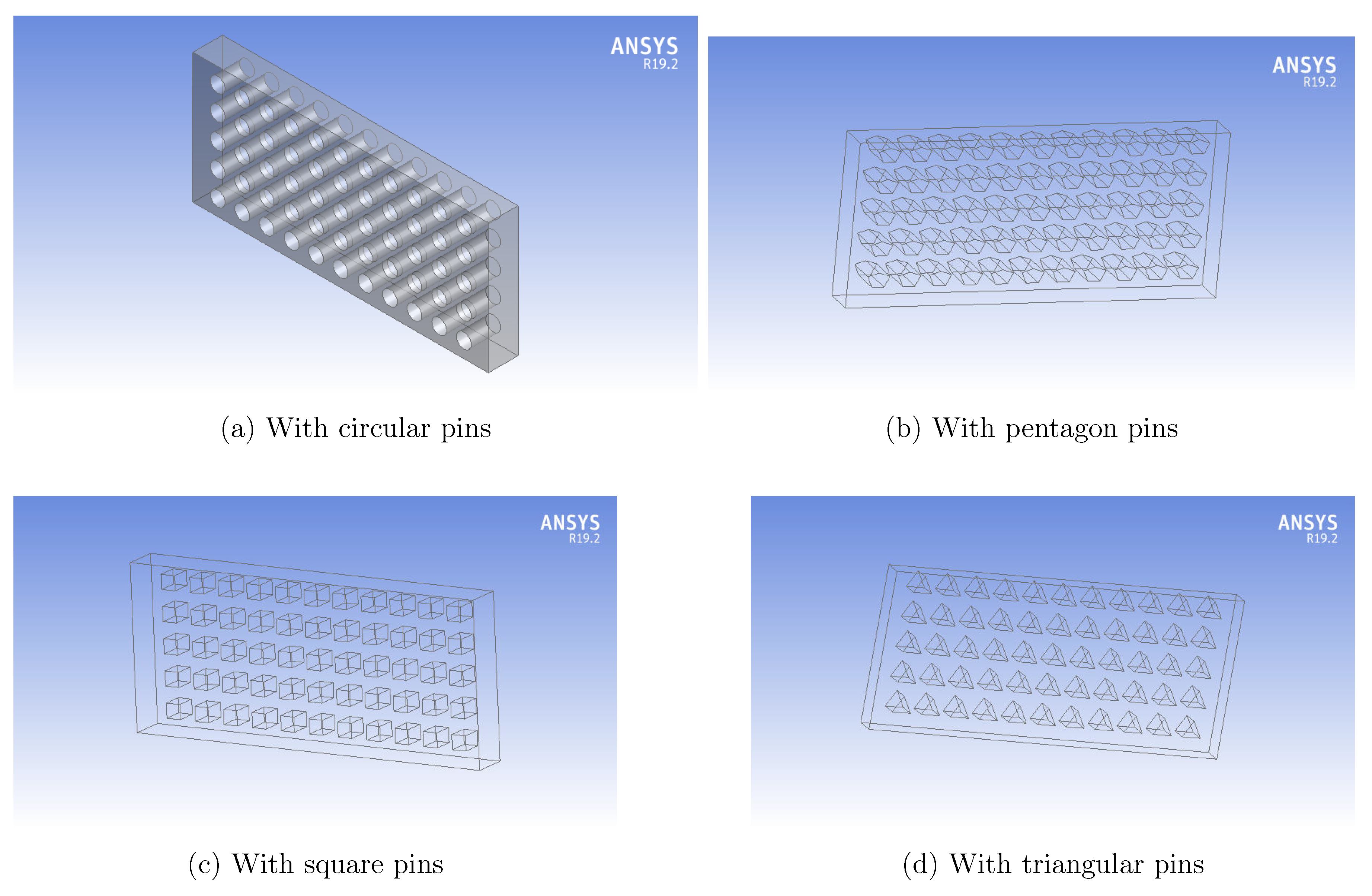
Figure 2.
Variation of Nusselt number with different with different fins profile.
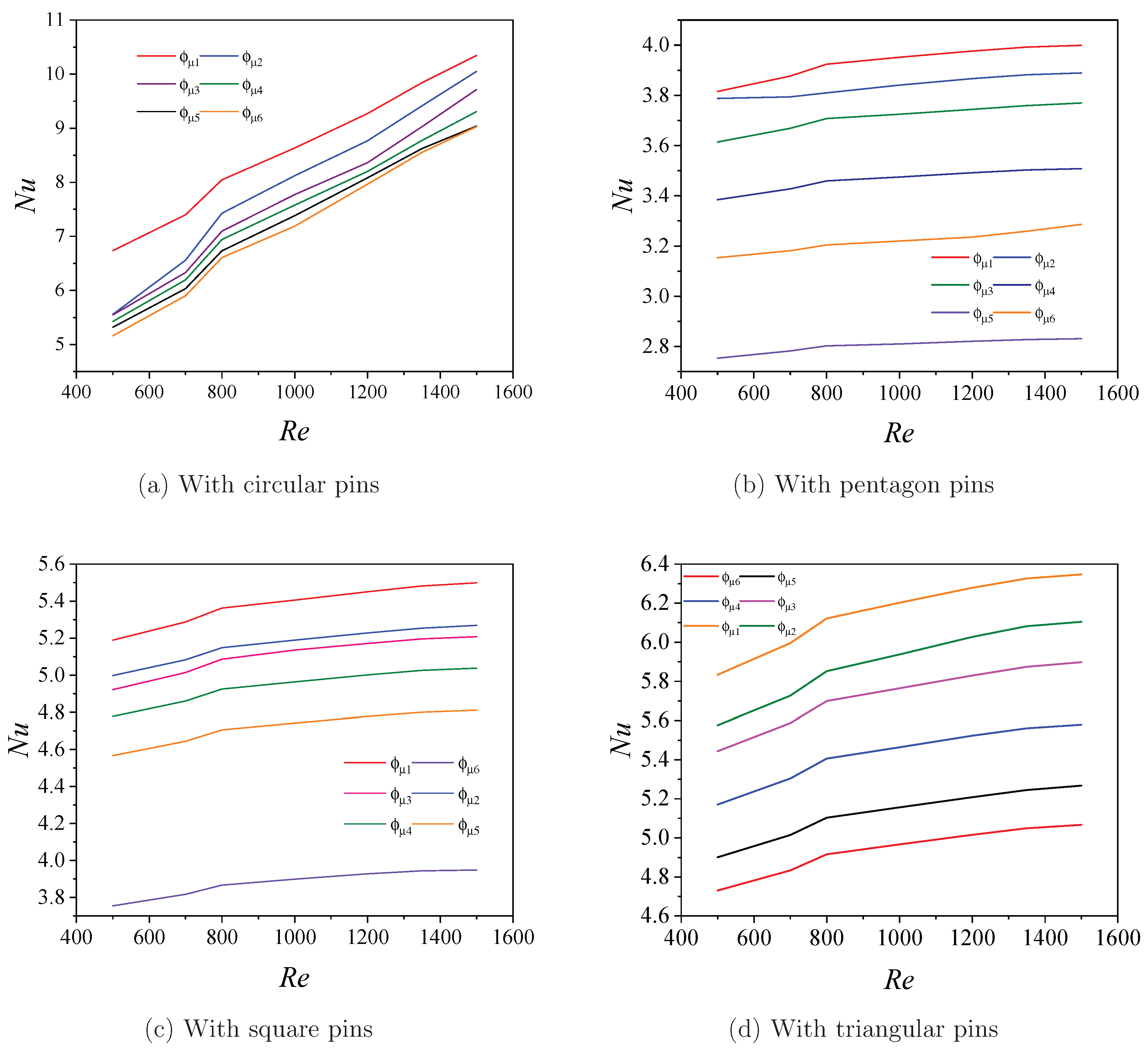
Figure 3.
Variation of Pressure drop with different with different fins profile.
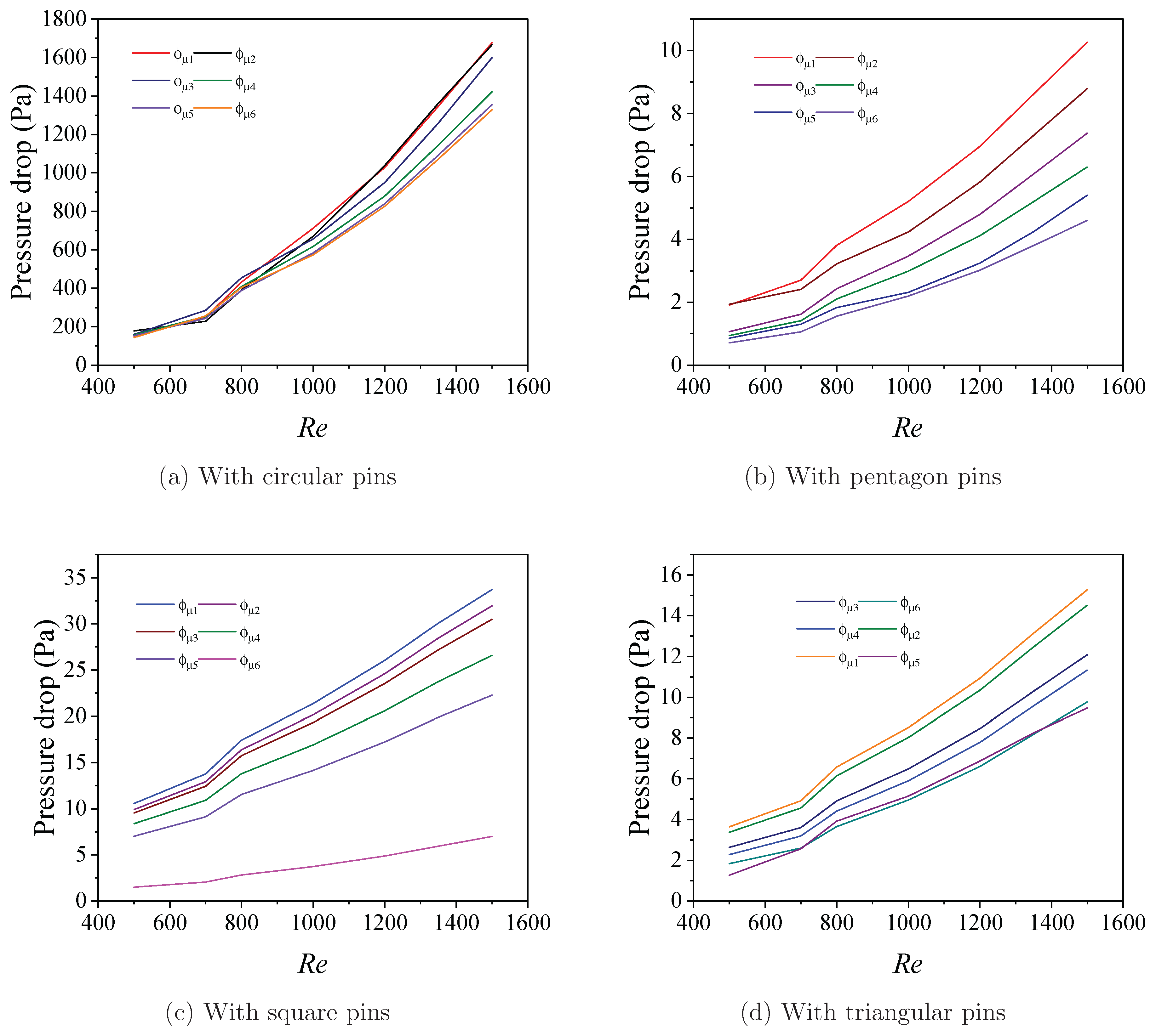
Figure 4.
Temperature profile at different geometries at Re = 500 for fin height = 35 m.
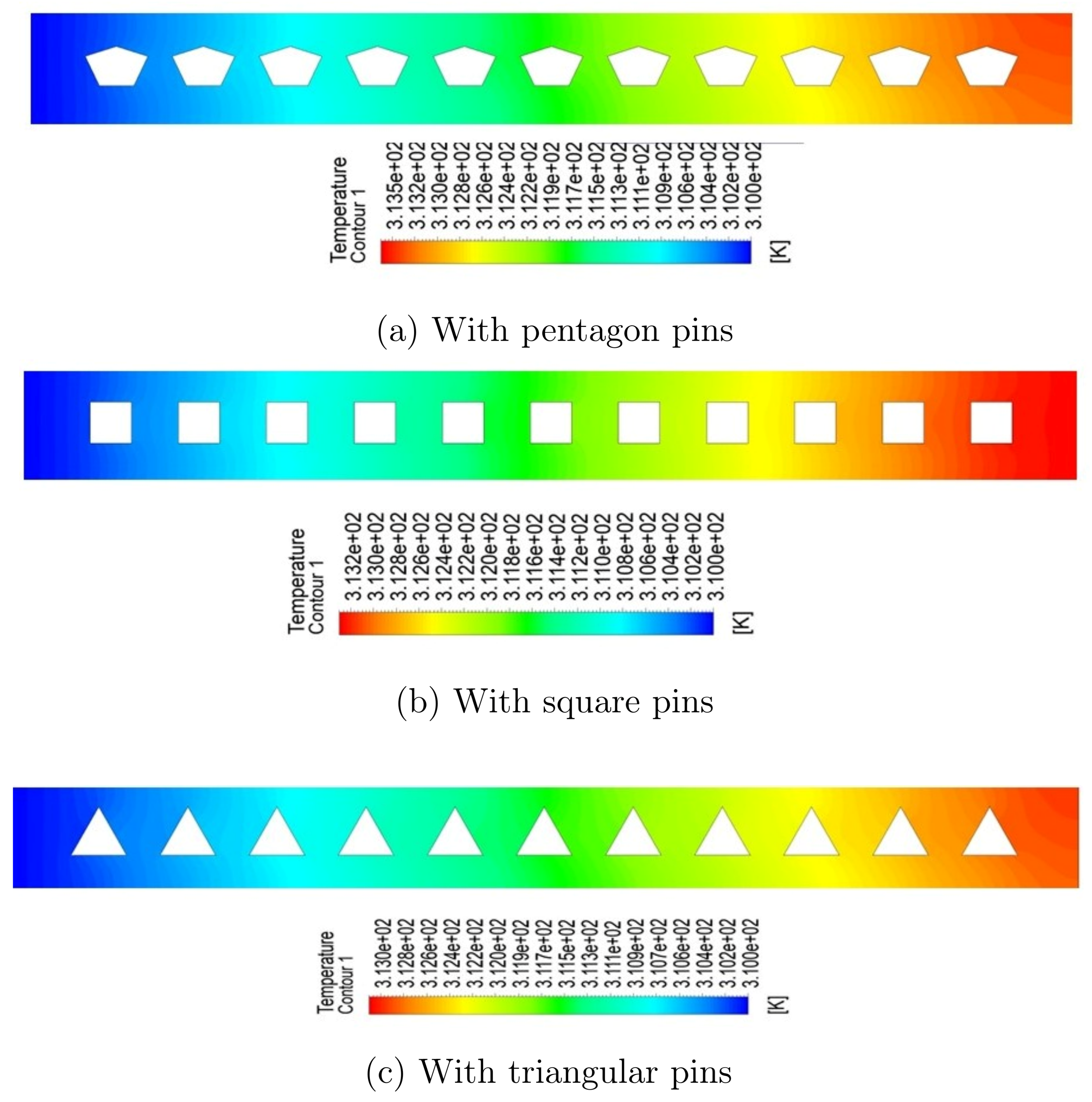
Figure 5.
Temperature profile at different geometries at Re = 500 for fin height = 60 m.
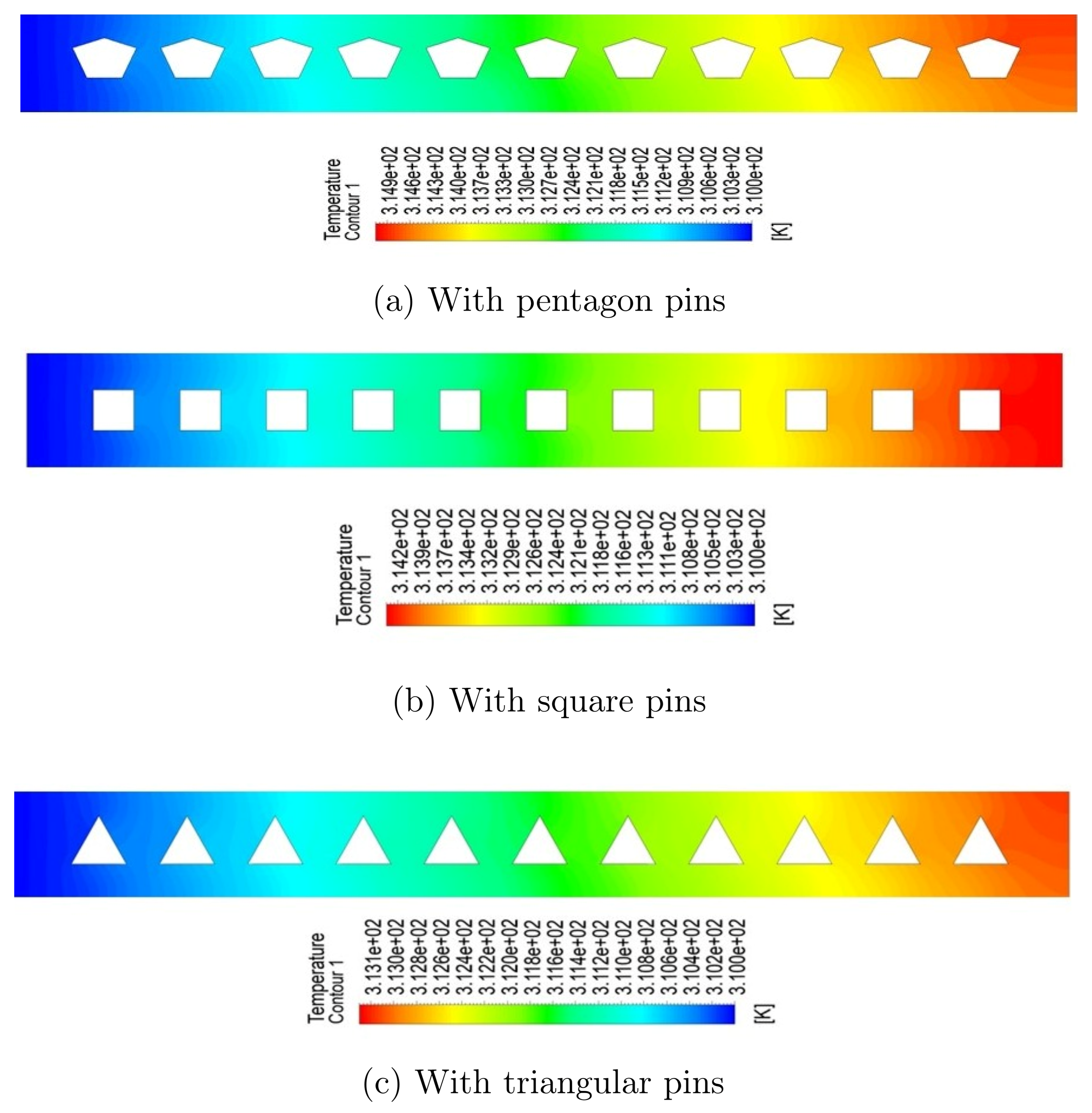
Figure 6.
Velocity profile at different geometries at Re = 500 for fin height = 35 m.
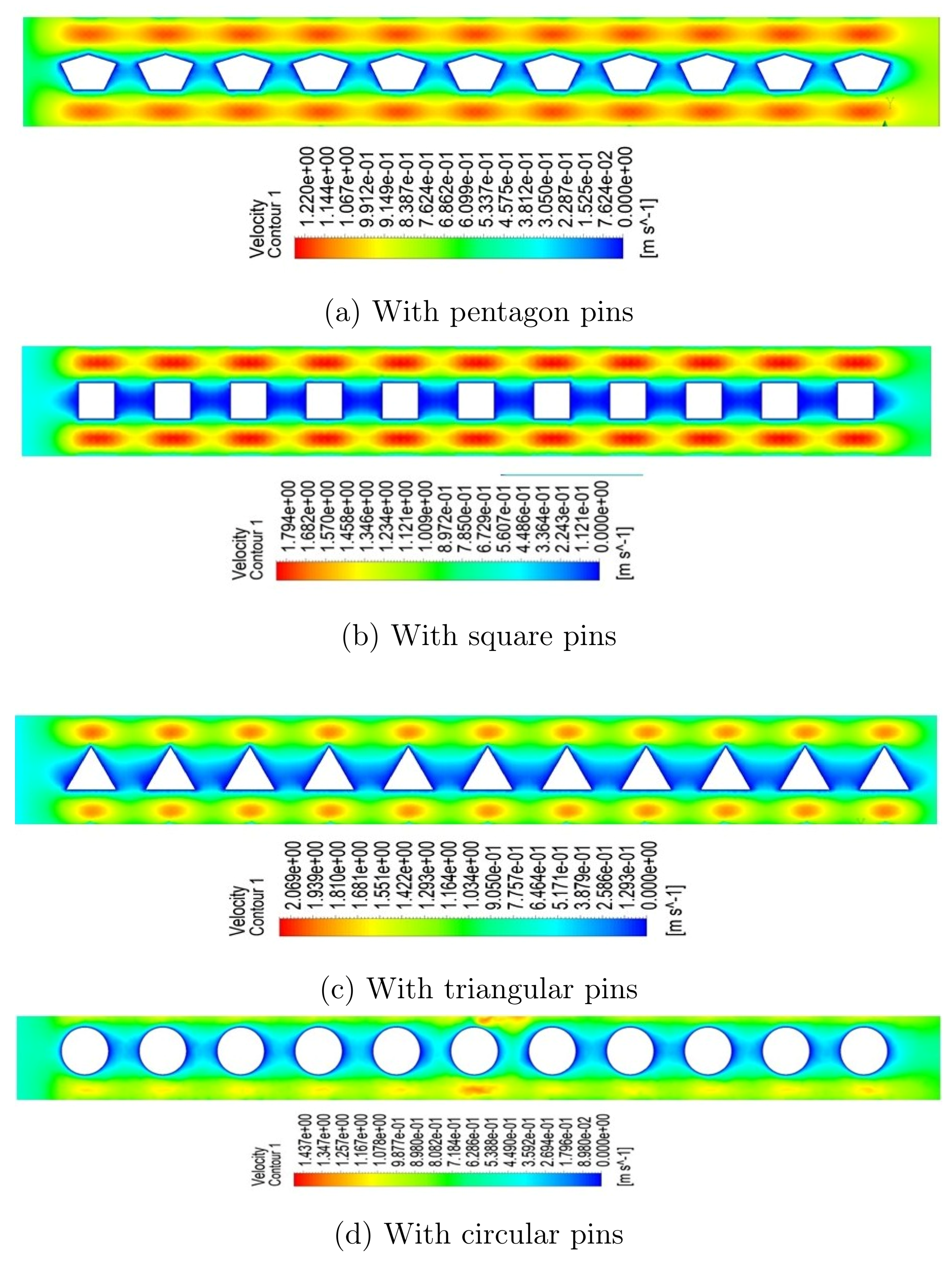
Figure 7.
Velocity profile at different geometries at Re = 500 for fin height = 60 m.
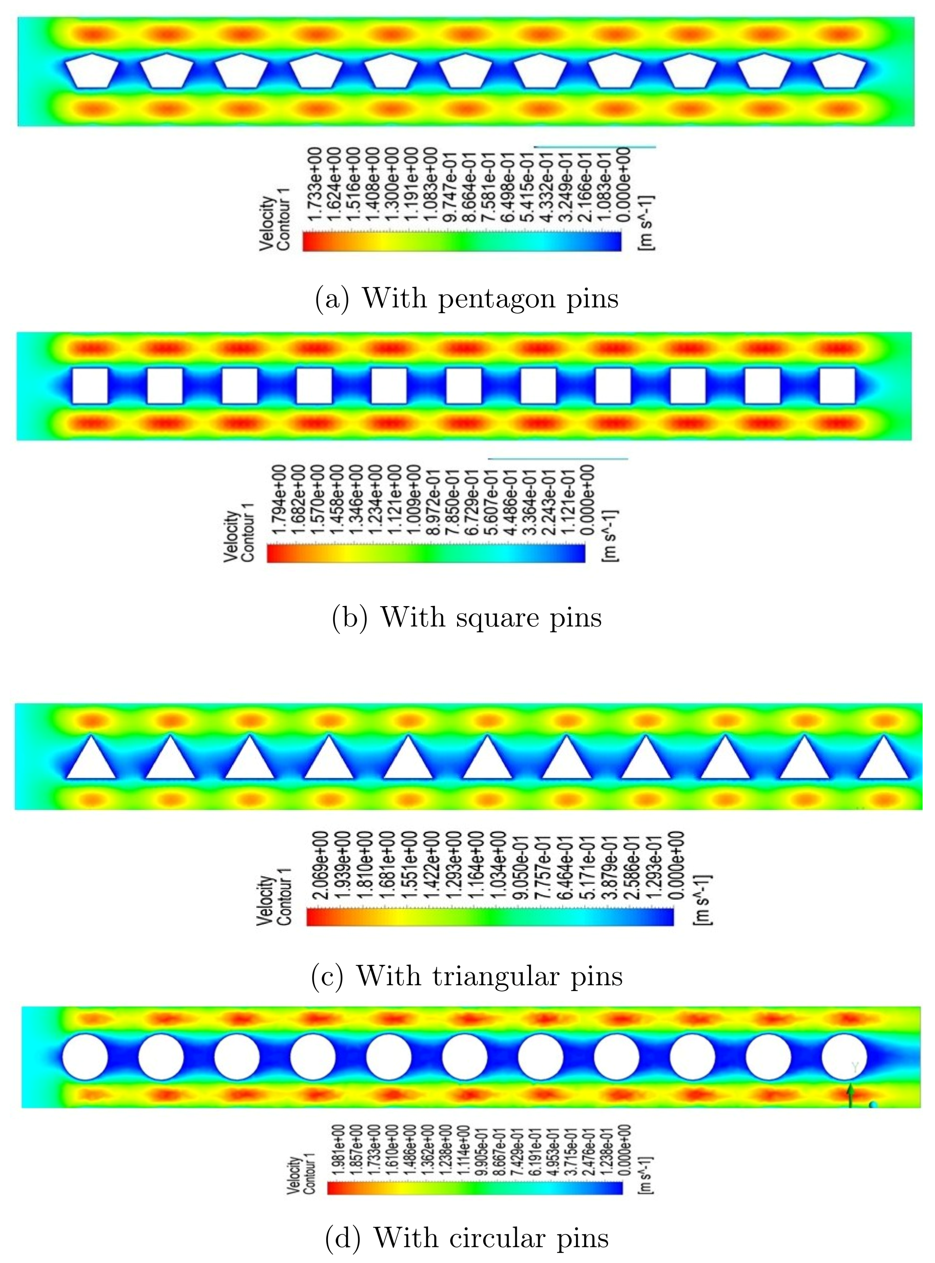

Table 1.
Geometrical dimensions of microchannel.
| Parameters | Value () | |
|---|---|---|
| Length of the channel | 600 | |
| Width of the channel | 265 | |
| Height of the channel | 62 | |
| Pin fins hydraulic diameter | 15 | |
| Spacing of pin fins | 50 | |
| Height of pin fin | 60, 55, 50, 45, 40, 35 | |
| Pin spacing to pin height ratio | 0.25, 0.272, 0.3, 0.33, 0.375, 0.428 | |
| Number of Pin fins | 55 |
Table 2.
Physical properties of coolant and heat sink.
| () | (J/kg-K) | K () | ||
|---|---|---|---|---|
| Fluid (water) | 981.3 | 4189 | 0.643 | 0.000598 |
| Heat Sink (copper) | 2719 | 871 | 273 | ——— |
Table 3.
Grid Independence test.
| Mesh size interval | Outlet temperature |
|---|---|
| Mesh1 (element size | 312.45 |
| Mesh2 (element size | 310.62 |
| Mesh3 (element size | 310.31 |
Disclaimer/Publisher’s Note: The statements, opinions and data contained in all publications are solely those of the individual author(s) and contributor(s) and not of MDPI and/or the editor(s). MDPI and/or the editor(s) disclaim responsibility for any injury to people or property resulting from any ideas, methods, instructions or products referred to in the content. |
© 2025 by the authors. Licensee MDPI, Basel, Switzerland. This article is an open access article distributed under the terms and conditions of the Creative Commons Attribution (CC BY) license (http://creativecommons.org/licenses/by/4.0/).
Copyright: This open access article is published under a Creative Commons CC BY 4.0 license, which permit the free download, distribution, and reuse, provided that the author and preprint are cited in any reuse.


