
Submitted:
27 September 2025
Posted:
02 October 2025
You are already at the latest version
Abstract
This work presents an analysis of a novel approach to motion planning for serial manipulators, based on an explicit and conservative representation of the configuration space (Cspace). Traditional sampling-based planners typically rely on implicit Cspace representations defined by workspace obstacles, resulting in limitations such as discrete configuration validity checks and the need for dense roadmaps with many samples. We investigate the Free Volume Graph (FVG) planner, which constructs roadmaps using hypercube volumes of verified free Cspace. This method enables a resolution-free certificate of continuous path validity, addressing key challenges in standard planning frameworks. Through a series of case studies involving 6- and 7-DOF manipulators across single and multi-query planning tasks, we evaluate the performance of FVG against Probabilistic Roadmap (PRM) method. Our findings indicate that FVG provides significant benefits in memory efficiency and computation time. Additionally, we examine the applicability of this approach to an open motion planning problem, identifying both its advantages and the remaining challenges in extending the method to broader scenarios.
Keywords:
Configuration space volumes
; serial-link manipulator
; motion planning
1. Introduction
Motion planning is a foundational technique in robotics, and configuration space () [1] representations are broadly applied, particularly in motion planning for manipulators. The for robot manipulators, however, are typically specified implicitly based on workspace (2D or 3D) obstacles, the manipulator’s link geometry and its forward kinematics. Implicitly specified poses certain challenges. First, though off-the-shelf libraries can find distances and free volumes in 3D workspaces [2,3,4], identifying corresponding free volumes in is more difficult. Instead, planning approaches often consider only individual configurations (rather than continuous sets or volumes of configurations). Evaluating configurations one-by-one may yield large roadmaps and leads to the second challenge: strictly guaranteeing collision-freedom on continuous plans. Checking validity only for configurations at regular intervals along a plan assume the validity between checked configurations and may require a large number of such checks down to a specified resolution. We address the challenges of implicit by deriving an explicit representation of free space volumes that are fast to compute and guarantees collision-freedom for all configurations within the volume.
We derive an explicit, conservation representation for volumes of free configurations, and we incorporate these free volumes into sampling-based planning to strengthen efficiency and correctness guarantees. We perform experiments for serial-link manipulators with 6-7 DOF (degrees of freedom) in single and multi-query settings, showing that our approach offers time, memory, and correctness improvements over PRM roadmaps (see 6).
2. Related Work
Sampling-based motion planners grow trees or graphs through a and often provide both theoretically robust convergence and efficient performance in practice [5,6,7,8,9,10,11,12,13,14,15,16]. We discuss related approaches for representation based on cell decomposition, learning, and optimization.
Cell decomposition methods, sometimes integrated with sampling-based methods [17,18], can offer resolution-completeness due to the underlying cell decomposition. However, decomposing the entire configuration space poses scalability challenges in higher dimensions. Other approaches deterministically sample configurations using the harmonic function to create a hierarchical cell decomposition [19] or define a resolution parameter to generate simplicial polytopes in a goal-biased direction to cover the [20]. The approach of [21] uses hyperspheres to approximate free regions for explicit or produces inexact approximations of implicit . Generally, determining cells or volumes for implicitly defined is a key challenge that this work addresses.
Several approaches have applied learning and optimization to represent the . Learned approximations of support fast planning [22,23]. Learning connectivity has enabled proofs of plan non-existence [24] and fast convergence when planning through narrow passages [25]. Optimization-based free space approximations using convex formulations offer strict validity certificates [26,27] or using nonlinear programming supports fast convergence [28]. General challenges of such learning and optimization approaches include inexactness or error of the representation, convergence guarantees, and overhead to construct the representation. Our work addresses these challenges with a representation that is conservative (we never misrepresent an obstacle configuration as free), robustly computable for serial manipulators in a 3D workspace, and efficient to construct on-the-fly during sampling-based planning.
Some previous studies utilized resolution-independent collision checking methods [29,30,31,32,33] to develop efficient Bounding Volumes (BVs) for robotic manipulator arms. This approach ensures that there are no missing parts of the robot’s rigid body during collision checking. In contrast, other methods [21,34,35,36,37,38] create conservative variants of bubbles, such as diamonds, burrs, hypercubes, or hyperspheres, of the to validate line segments. These methods utilize heuristic functions, like A*, for safety assessments, aiming to establish a continuous, collision-free path that connects the centers of intersecting volumes. In this work, we use the similar approach to study and compare the efficiency of hypercube volumes for serial manipulators in high-dimensional space.
3. Problem Definition
We address geometric motion planning for serial manipulators with revolute joints operating in a 3D workspace.
A geometric motion planning problem consists of a configuration space composed of disjoint free space and obstacle region , a start configuration , and goal configuration [39]. A feasible plan is a path , such that , , and .
Following common practice for manipulator motion planning, we start from an implicitly defined in terms of a 3D workspace composed of disjoint free and obstacle regions coupled with the manipulator forward kinematics, , to determine all manipulator workspace points at a particular configuration. We then define components as and .
Our analysis assumes that the maximum workspace displacement occurs at the manipulator’s end-effector point. Generally, this assumption holds for the typical case of serial link manipulators with thin links along straight lines between joints, though manipulators with differently-shaped link geometries would require additional considerations.
4. Free Space Volumes
We find volumes of free space to support efficient and correct motion planning. While direct methods exist to find separation and penetration distances in [2,3], the typical implicit representations present challenges to finding similar exact distances in . Instead, we find bounds on distances relative to displacement. These bounds determine volumes to enable the construction of compact planning graphs with guaranteed continuity.
We identify configuration volumes from an upper bound on displacement and lower bound on separation. Specifically, two conditions determine the volume around a configuration (see Section 4.1). First, for all configurations in the volume, the actual displacement from is no more than the bound (4.2). Second, the bound is less than the workspace separation at (4.3). When these two conditions hold, all points in the volume are free.
4.1. Preliminary Definitions and Bound Condition
We first define separation/penetration in terms of metric and signed distance functions [40]. Then, we will precisely state the bound condition for volumes.
We write workspace metric functions as and metric functions as , where a metric function is non-negative, symmetric, satisfies the triangle inequality, and .
4.1.1. Signed Distance Functions
In general, a signed distance function determines a level of separation or penetration based on distance to a boundary .
Definition 1.
A Signed Distance Function (SDF) is,
where is a distance to free space boundary .
SDFs may incorporate metric functions operating in either or .
Definition 2.
A Workspace SDF : finds separation or penetration using a workspace metric,
where are points on the robot at that are respectively free or colliding, is an obstacle point, and is on the obstacle surface.
Definition 3.
A Cspace SDF finds separation or penetration using a metric,
where is a configuration on the free space boundary.
4.1.2. Bound Condition
We address SDFs for implicit of serial manipulators by identifying bounds to ensure separation. The idea is to satisfy two properties between a free configuration and another configuration . First, we need an upper bound on workspace displacements going from to . Second, we need a lower bound on separation distance at . These properties form the following inequality,
where are corresponding robot points at , with the greatest displacement. The first part of the inequality bounds the maximum workspace displacement; from to , where robot points move by at most . The second part of the inequality is the lower bound on separation, i.e., distance from to is less than separation at . When this inequality holds, must also be free.
4.2. Workspace Displacement Bound
We now determine the upper bounds on workspace displacement for serial manipulators with revolute joints, addressing the first part of relation (1). Our analysis considers the end-effector, assuming it is the point of maximum displacement, which holds for typical cases of manipulators with thin links. Several prior research [29,36,37,38] used arc length at each joint to define displacement within convex volumes of ,
where represents the radius of the cylinder whose axis is collocated with the axis of the joint and that encloses all the links starting from joint to the end-effector (see Figure 1a). The expression for is a conservative upper bound on the workspace displacement of any point on the manipulator when the configuration changes from to . Moving the robot from configuration to an arbitrary configuration within a lower bound () means that no point on the kinematic chain will move more than separation (in case of free space displacement) and thus no collision will occur.
We use the chord length (see Figure 1b) between and to define tighter bound on our volumes,
Hence, the inequality can be restated as,
4.3. Separation Bound
Next, we use distances that lower-bound separation to identify free space volumes, addressing the second part of relation in 1. First, displacements from a free configuration that are less than separation must also yield another free configuration (Lemma 1). Then, we determine free volumes based on the separation distance (Theorem 1).
Lemma 1.
Given configurations , when and relation holds, then also.
Proof.
From Figure 1b, the maximum workspace displacement from ) to cannot exceed . When this displacement is less than workspace separation , the robot has not moved far enough to collide with any obstacle, so must also be free. □
Theorem 1.
Let be the hypercube centered at with radial length in . Hypercube is fully in the free space, if . Similarly, for if .
Proof.
Using Theorem 1, we construct hypercubes with circumscribed radius where is the center. Given the circumradius of a hypercube, we get the side length s in n-dimension, as
Our hypercubes at any configuration is axis-aligned and the bounding box along each joint axis can be represented by set of linear inequalities.
Here, refers to lower limit and is upper limit of an edge (1D) at each dimension. We can determine the lower and upper limit along each joint axis of hypercube for known centroid configuration and its side length s by computing and .
The result of Theorem 1 is an explicit representation of that requires only an implicit specification in terms of workspace obstacles and robot kinematics. Specifically, we have derived a conservative under-approximation of the free configuration space. That is, every configuration within an identified free hypercube must necessarily be free, while some configurations just beyond the boundaries of could—and typically will—also be free. Further, the free hypercubes can be efficiently computed at any free configuration just by finding the workspace separation distance at (computable using off-the-shelf libraries [2,3]) and computing hypercube circumradius from the robot link lengths. Despite the conservatism of the approximation, such efficiently computable free space volumes offer a new capability to reason about sets of free configurations. In the next section, we will apply the free space volumes of Theorem 1 to strengthen efficiency and correctness guarantees of sampling-based planners.
5. Free Volume Graphs
We construct compact and certifiably continuous roadmaps as Free Volume Graphs (FVGs) where nodes are free space volumes and edges represent valid plans between nodes.
5.1. Graph Construction
Our approach to constructing FVGs is similar to PRM construction [8], with two key properties to support sparsity and guarantee the continuity of edges. First, each FVG node represents a volume or set of configurations. In contrast, nodes in baseline planning approaches commonly represent a single configuration. We further promote sparsity by rejecting new configurations enclosed by existing free volumes. Second, we ensure FVG edge continuity by only adding edges between free volumes that intersect. In contrast, baseline planners commonly check validity at discrete configurations along regular intervals between nodes. These two properties result in FVGs that are compact roadmaps in which graph paths guarantee the existence of continuous, collision-free motion plans.
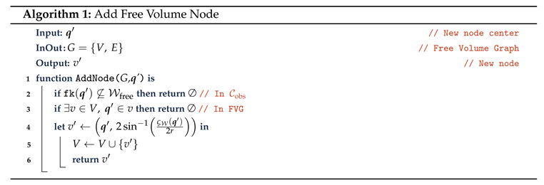
5.1.1. Nodes
We add a new node to the FVG in a similar manner as PRMs by sampling a configuration and attempting to connect the existing graph to the new configuration (see Figure 1). However, there are two important differences in adding FVG nodes. First, when a newly sampled node is enclosed by a volume already in the FVG, we reject the sample (see Figure 2). Second, we must store the volume information for each node. In the case of hypercube nodes , we store the center configuration and the edge length as described in Theorem 1. The additional volume information means that each FVG node will require more memory than a PRM node. However, our experimental results in Section 6 show that vastly fewer nodes are required for an FVG compared to a PRM, resulting in overall memory savings, even though each FVG node takes more space. Finally, our implementation in Section 6 is multi-directional and grows FVGs from a start and goal, similar to RRT-Connect [6], for faster convergence.
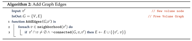
5.1.2. Edges
We add edges to the FVG between intersecting volume nodes (see Algorithm 2 and Figure 3). When adding a new node , we create an edge to any existing node in the FVG that intersects . Compared to validity checking at regular intervals, adding edges based on intersection guarantees the existence of continuous, collision-free plans between nodes.
We find an intersection/overlap between any two hypercubes ( and ) using the edge bounding condition, such that the maxima of the lower limit are strictly less than or equal to the minima of the upper limit of the hypercubes.
The edges are formed between the centers of hypercubes by interpolating through the intersecting regions between them.
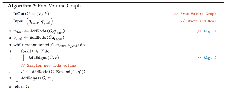
5.1.3. Overall Graph
Finally, Algorithm 3 describes overall FVG construction. We progressively grow the graph until a start and goal node are in the same connected component.
5.2. Analysis
An FVG is an explicit, conservative representation of free space and valid motion plans. We provide a brief proof that an FVG path certifies the existence of a continuous motion plan, offering a stronger correctness guarantee than checking the validity of only individual configurations.
Proposition 1.
Let be an FVG and be path through FVG (i.e., each and each ). For a motion planning problem from to , where and , path p guarantees the existence of a continuous, collision-free motion plan from to .
Proof.
We prove this by induction. For the basis, means path p contains a free configuration for the start. For the inductive step, means and are intersecting volumes, so there exists a collision-free plan from every to every . By induction, there exists a continuous, collision-free plan from to . □
Proposition 1 shows that FVGs offer strict correctness guarantees by connecting nodes with intersecting volumes to provide a certificate of continuous motion plan existence.
6. Experimental Results
We evaluate the efficiency and correctness of our algorithm with a baseline PRM [8] from OMPL [42] to analyze for sampling density, multi-query, and uniform-randomness criteria during roadmap construction, collision checking and planning.
6.1. Experimental Setup
We run tests for the three manipulators and environments shown in Figure 4. The environments cover pick and place, kitchen, and industrial workcell tasks, and the robots are 6 or 7 DOF UR5, Franka, and Schunk LWA4D manipulators. We implement our planner through OMPL [42], model robot kinematics using Amino [43], and check collisions using the Collision Library [3]. We run our experiments on AMD 9 7950X CPU with 16 cores at 4.5GHz.
6.2. Bound Consistency and Tightness
We compare the consistency of our upper bound () on workspace displacement with the SNG bound [35], which employs the Euclidean distance metric in Equation 2. In contrast, our approach uses the Manhattan distance metric. Despite this difference in metric, we observe that both methods ensure a tight upper bound on workspace displacement, as illustrated in Figure 5.
Interestingly, the choice of distance metric can influence how tight the upper bound on workspace displacement is, allowing for a potentially more precise estimate in .
6.3. Time and Memory Use
We construct roadmaps using the baseline planner and our approach (see Table 1). We varied robot and obstacle locations within the scenes to create different and then constructed roadmaps covering several goal configurations. Each table row shows averages plus-minus standard deviation error for 50 trials of one roadmap construction problem.
6.3.1. Overall Time and Memory
We compare the overall time and memory use of our method and the baseline PRM to determine speedup and memory reduction. We compute speedup as , where T is time use, and we compute memory reduction as , where M is memory use. We note that each FVG node requires one additional value to store the hypercube circumradius compared to PRM nodes that store only the configuration.
Overall, the results show FVGs require (times) less memory than PRMs to cover the same configurations in tested scenes. Time use improves up to for some scenes, but is slightly slower () in others, which we describe next through profiling results.
6.3.2. Collision Checking Time
We profiled the baseline and our approach to determine bottlenecks and subroutine costs (see Table 2). We used the gperftools [44] statistical profiler and ran 100 trials in each environment setting to collect sufficient statistics to identify bottlenecks and costs.
The bottlenecks for both our algorithm and the baseline are collision and distance checking. We compute average time T for a subroutine as , where t is the total running time, p is the percent of time spent in the subroutine (from profiling), and n is the number of subroutines calls (from a counter in the program). The FVGs required fewer collision-related calls than PRMs largely due to the fewer FVG nodes. However, distance checks are more expensive than collision checks, leading to overall similar running times.
7. Discussion and Future Work
This work introduces an approach to constructing conservative approximations of free space for serial manipulators and presents the Free Volume Graph (FVG) planning framework. The FVG enables the generation of sparse roadmaps using hypercubes to determine certification of continuous collision-free paths. Experimental comparisons demonstrate that, relative to traditional Probabilistic Roadmap Methods (PRM), the FVG approach achieves comparable construction times, up to 23× lower memory usage, and provides stronger correctness guarantees due to its conservative volumetric representation.
While the core ideas build upon earlier efforts in conservative motion planning and volumetric approximations [e.g., [29,36,37,38]], the FVG method was developed with extensibility in mind. In particular, it opens new possibilities for reasoning not only about the free space but also about the configuration space () regions that are in collision or out-of-bounds. This dual characterization could be highly beneficial for improving rejection sampling efficiency by explicitly modeling invalid regions, thereby reducing the sampling burden in complex or constrained environments.
A key avenue for future work involves extending the FVG framework to approximate the boundary and interior of the invalid configuration space. If tight and enclosed intersections of high-dimensional hypercubes can be accurately computed, this would allow the construction of conservative collision regions, complementing the current free-space approximations. Such capability could significantly advance the development of tools for proving motion plan infeasibility, a critical but underexplored aspect of motion planning.
Additionally, we further plan to investigate the application of FVG in real-time planning scenarios, particularly for manipulators operating in high-dimensional and cluttered workspaces. Enhancements in incremental graph construction, parallelism, and data structure optimization [45,46,47,48,49] could further improve FVG’s practical deployment in robotics systems.
Acknowledgments
I would like to thank Neil Dantam for the suggestions and feedback provided during the development of this work.
References
- Lozano-Pérez, T. Spatial planning: A configuration space approach. IEEE Transactions on Computers 1983, 100, 108–120. [Google Scholar] [CrossRef]
- Gilbert, E.G.; Johnson, D.W.; Keerthi, S.S. A fast procedure for computing the distance between complex objects in three-dimensional space. IEEE Journal on Robotics and Automation 1988, 4, 193–203. [Google Scholar] [CrossRef]
- Pan, J.; Chitta, S.; Manocha, D. FCL: A general purpose library for collision and proximity queries. In Proceedings of the 2012 IEEE International Conference on Robotics and Automation (ICRA); 2012; pp. 3859–3866. [Google Scholar]
- Coumans, E.; Bai, Y. PyBullet, a Python module for physics simulation for games, robotics and machine learning. http://pybullet.org, 2016–2021.
- LaValle, S.M. Rapidly-exploring random trees: A new tool for path planning. Technical Report TR-98-11, Computer Science Deptartment, Iowa State University, 1998.
- Kuffner, J.J.; LaValle, S.M. RRT-connect: An efficient approach to single-query path planning. In Proceedings of the 2000 IEEE International Conference on Robotics and Automation (ICRA), 2000, Vol. 2, pp. 995–1001 .
- LaValle, S.M.; Kuffner, J.J. Randomized kinodynamic planning. The International Journal of Robotics Research 2001, 20, 378–400.
- Kavraki, L.E.; Švestka, P.; Latombe, J.C.; Overmars, M.H. Probabilistic roadmaps for path planning in high-dimensional configuration spaces. IEEE Transactions on Robotics 1996, 12, 566–580. [CrossRef]
- Kavraki, L.E.; Kolountzakis, M.N.; Latombe, J.C. Analysis of probabilistic roadmaps for path planning. IEEE Transactions on Robotics 1998, 14, 166–171. [CrossRef]
- Hsu, D.; Latombe, J.C.; Motwani, R. Path Planning in Expansive Configuration Spaces. International Journal of Computational Geometry & Applications 1999, 09, 495–512. [Google Scholar] [CrossRef]
- Karaman, S.; Frazzoli, E. Sampling-based algorithms for optimal motion planning. The International Journal of Robotics Research 2011, 30, 846–894.
- Şucan, I.A.; Kavraki, L.E. Kinodynamic motion planning by interior-exterior cell exploration. In Proceedings of the Algorithmic Foundation of Robotics VIII: Selected Contributions of the Eight International Workshop on the Algorithmic Foundations of Robotics. Springer; 2009; pp. 449–464. [Google Scholar]
- Jaillet, L.; Cortés, J.; Siméon, T. Sampling-Based Path Planning on Configuration-Space Costmaps. IEEE Transactions on Robotics 2010, 26, 635–646. [CrossRef]
- Devaurs, D.; Siméon, T.; Cortés, J. Enhancing the transition-based RRT to deal with complex cost spaces. In Proceedings of the 2013 IEEE International Conference on Robotics and Automation (ICRA). IEEE; 2013; pp. 4120–4125. [Google Scholar]
- Dobson, A.; Bekris, K.E. Sparse roadmap spanners for asymptotically near-optimal motion planning. The International Journal of Robotics Research 2014, 33, 18–47. [CrossRef]
- Janson, L.; Schmerling, E.; Clark, A.; Pavone, M. Fast marching tree: A fast marching sampling-based method for optimal motion planning in many dimensions. The International Journal of Robotics Research 2015, 34, 883–921. [CrossRef]
- Zhang, L.; Kim, Y.J.; Manocha, D. A hybrid approach for complete motion planning. In Proceedings of the 2007 IEEE/RSJ International Conference on Intelligent Robots and Systems (IROS), 2007, pp. 7–14.
- Varadhan, G.; Krishnan, S.; Sriram, T.; Manocha, D. A simple algorithm for complete motion planning of translating polyhedral robots. The International Journal of Robotics Research 2006, 25, 1049–1070.
- Rosell, J.; Vázquez, C.; Pérez, A. C-space decomposition using deterministic sampling and distance. In Proceedings of the 2007 IEEE/RSJ International Conference on Intelligent Robots and Systems (IROS). IEEE; 2007; pp. 15–20. [Google Scholar]
- Upadhyay, A.; Goldfarb, B.; Ekenna, C. Incremental path planning algorithm via topological mapping with metric gluing. In Proceedings of the 2022 IEEE/RSJ International Conference on Intelligent Robots and Systems (IROS). IEEE; 2022; pp. 1290–1296. [Google Scholar]
- Shkolnik, A.; Tedrake, R. Sample-based planning with volumes in configuration space. arXiv preprint arXiv:1109.3145 2011.
- Pan, J.; Manocha, D. Efficient configuration space construction and optimization for motion planning. Engineering 2015, 1, 046–057. [Google Scholar] [CrossRef]
- Kim, D.; Kwon, Y.; Yoon, S.E. Dancing PRM*: Simultaneous planning of sampling and optimization with configuration free space approximation. In Proceedings of the 2018 IEEE International Conference on Robotics and Automation (ICRA). IEEE; 2018; pp. 7071–7078. [Google Scholar]
- Li, S.; Dantam, N.T. A sampling and learning framework to prove motion planning infeasibility. The International Journal of Robotics Research 2023, 42, 938–956. [CrossRef]
- Li, S.; Dantam, N.T. Sample-Driven Connectivity Learning for Motion Planning in Narrow Passages. In Proceedings of the 2023 IEEE International Conference on Robotics and Automation (ICRA),, 2023.
- Amice, A.; Dai, H.; Werner, P.; Zhang, A.; Tedrake, R. Finding and Optimizing Certified, Collision-Free Regions in Configuration Space for Robot Manipulators. In Proceedings of the Workshop on the Algorithmic 106 Foundations of Robotics (WAFR), 2022.
- Dai, H.; Amice, A.; Werner, P.; Zhang, A.; Tedrake, R. Certified polyhedral decompositions of collision-free configuration space. The International Journal of Robotics Research 2024, 43, 1322–1341. [CrossRef]
- Petersen, M.; Tedrake, R. Growing convex collision-free regions in configuration space using nonlinear programming. arXiv preprint arXiv:2303.14737 2023.
- Quinlan, S. Real-time modification of collision-free paths; Stanford University, 1995.
- Schwarzer, F.; Saha, M.; Latombe, J.C. Exact collision checking of robot paths. Algorithmic foundations of robotics V 2004, pp. 25–41.
- Schwarzer, F.; Saha, M.; Latombe, J.C. Adaptive dynamic collision checking for single and multiple articulated robots in complex environments. IEEE Transactions on Robotics 2005, 21, 338–353. [Google Scholar] [CrossRef]
- Tarbouriech, S.; Suleiman, W. On bisection continuous collision checking method: Spherical joints and minimum distance to obstacles. In Proceedings of the 2018 IEEE International Conference on Robotics and Automation (ICRA). IEEE; 2018; pp. 7613–7619. [Google Scholar]
- Tarbouriech, S.; Suleiman, W. Bi-objective motion planning approach for safe motions: Application to a collaborative robot. Journal of Intelligent & Robotic Systems 2020, 99, 45–63. [Google Scholar]
- Bialkowski, J.; Otte, M.; Karaman, S.; Frazzoli, E. Efficient collision checking in sampling-based motion planning via safety certificates. The International Journal of Robotics Research 2016, 35, 767–796. [Google Scholar] [CrossRef]
- Yang, L.; Lavalle, S.M. The sampling-based neighborhood graph: An approach to computing and executing feedback motion strategies. IEEE Transactions on Robotics and Automation 2004, 20, 419–432. [Google Scholar] [CrossRef]
- Ademovic, A.; Lacevic, B. Path planning for robotic manipulators using expanded bubbles of free c-space. In Proceedings of the 2016 IEEE International Conference on Robotics and Automation (ICRA). IEEE; 2016; pp. 77–82. [Google Scholar]
- Lacevic, B.; Rocco, P. Sampling-based safe path planning for robotic manipulators. In Proceedings of the 2010 IEEE 15th Conference on Emerging Technologies &, 2010, Factory Automation (ETFA 2010). IEEE; pp. 1–7. [Google Scholar]
- Lacevic, B.; Osmankovic, D. Improved C-space exploration and path planning for robotic manipulators using distance information. In Proceedings of the 2020 IEEE International Conference on Robotics and Automation (ICRA). IEEE; 2020; pp. 1176–1182. [Google Scholar]
- LaValle, S.M. Planning algorithms; Cambridge university press, 2006.
- Hauser, K. Semi-infinite programming for trajectory optimization with non-convex obstacles. The International Journal of Robotics Research2021, 40, 1106–1122.
- Zhang, L.; Kim, Y.J.; Manocha, D. A Fast and Practical Algorithm for Generalized Penetration Depth Computation. In Proceedings of the, Proceedings of Robotics: Science and Systems 2007.
- Şucan, I.A.; Moll, M.; Kavraki, L.E. The open motion planning library. EEE Robotics Automation Magazine 2012, 19, 72–82.
- Dantam, N.T. Robust and efficient forward, differential, and inverse kinematics using dual quaternions. The International Journal of Robotics Research2021, 40, 1087–1105.
- Ghemawat, S. (gperftools) Google Performance Tools, 2024. Accessed: 09/12/2024.
- Thomason, W.; Kingston, Z.; Kavraki, L.E. Motions in microseconds via vectorized sampling-based planning. In Proceedings of the 2024 IEEE International Conference on Robotics and Automation (ICRA). IEEE; 2024; pp. 8749–8756. [Google Scholar]
- Sundaralingam, B.; Hari, S.K.S.; Fishman, A.; Garrett, C.; Van Wyk, K.; Blukis, V.; Millane, A.; Oleynikova, H.; Handa, A.; Ramos, F.; et al. CuRobo: Parallelized Collision-Free Robot Motion Generation. In Proceedings of the 2023 IEEE International Conference on Robotics and Automation (ICRA), 2023, pp. 8112–8119. [CrossRef]
- Schulman, J.; Duan, Y.; Ho, J.; Lee, A.; Awwal, I.; Bradlow, H.; Pan, J.; Patil, S.; Goldberg, K.; Abbeel, P. Motion planning with sequential convex optimization and convex collision checking. The International Journal of Robotics Research2014, 33, 1251–1270.
- Fishman, A.; Murali, A.; Eppner, C.; Peele, B.; Boots, B.; Fox, D. Motion policy networks. In Proceedings of the Conference on Robot Learning. PMLR; 2023; pp. 967–977. [Google Scholar]
- Mukadam, M.; Dong, J.; Yan, X.; Dellaert, F.; Boots, B. Continuous-time Gaussian process motion planning via probabilistic inference. The International Journal of Robotics Research2018, 37, 1319–1340.
Figure 1.
Figures show an N-link serial manipulator projecting (a) axis-aligned case, and (b) distance between any two non-zero configurations and in .
Figure 1.
Figures show an N-link serial manipulator projecting (a) axis-aligned case, and (b) distance between any two non-zero configurations and in .
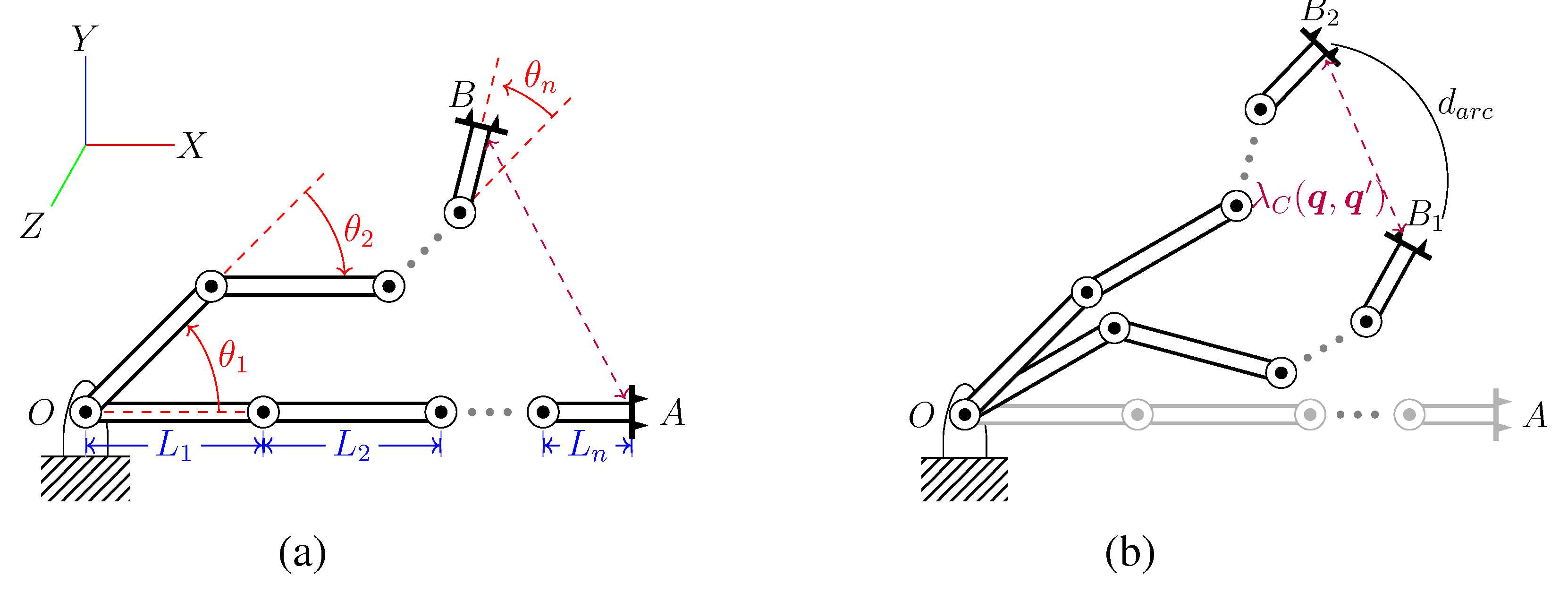
Figure 2.
Selective sampling of a new node volume in .
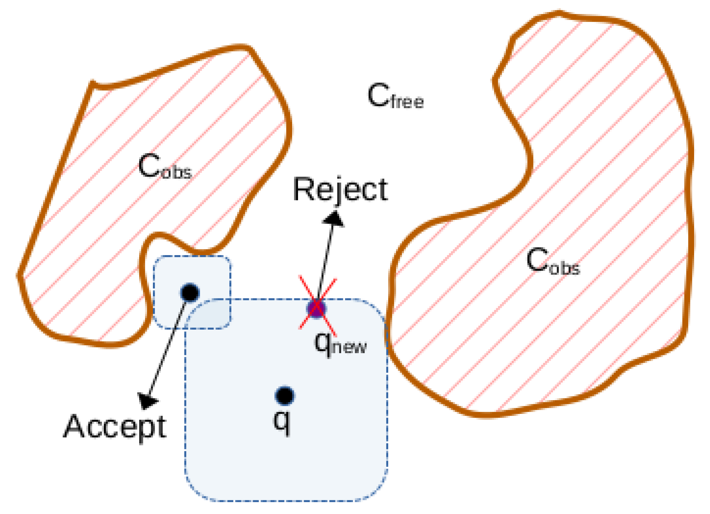
Figure 3.
Connecting nodes of intersecting volumes of
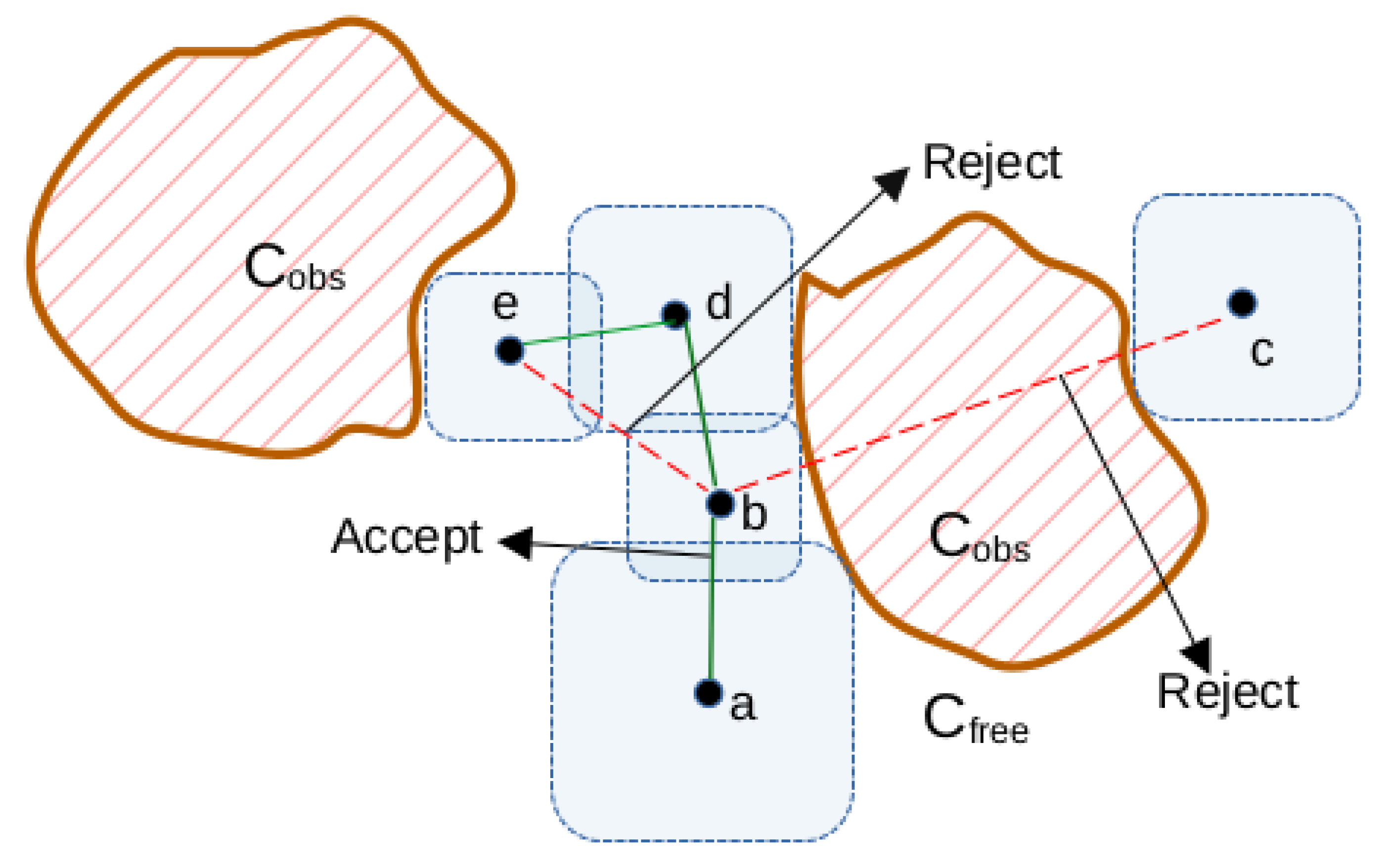
Figure 4.
Figure shows a (a) single query scenario for UR5 robot, where it moves rod from start to goal in the presence of a thin wall. (b) multi-query kitchen setting for Franka arm making motion from sink to dishwasher to cupboard. (c) multi-query industry workcell setting for Schunk arm arranging objects between a table and a shelf.
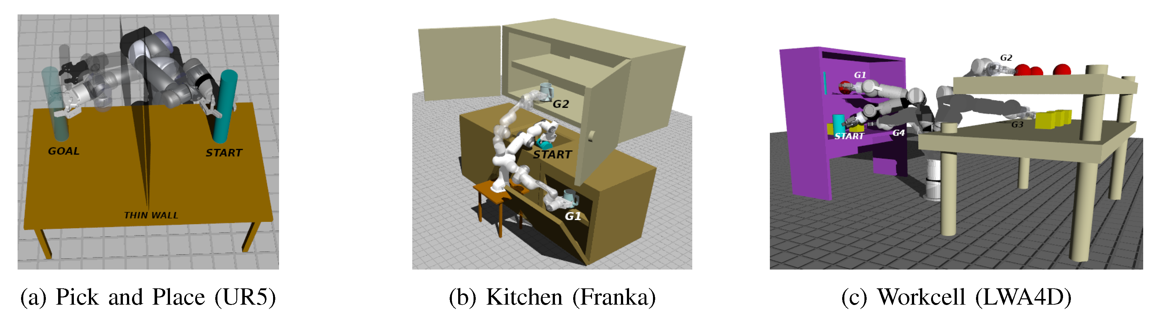
Figure 5.
FVG vs. SNG bound
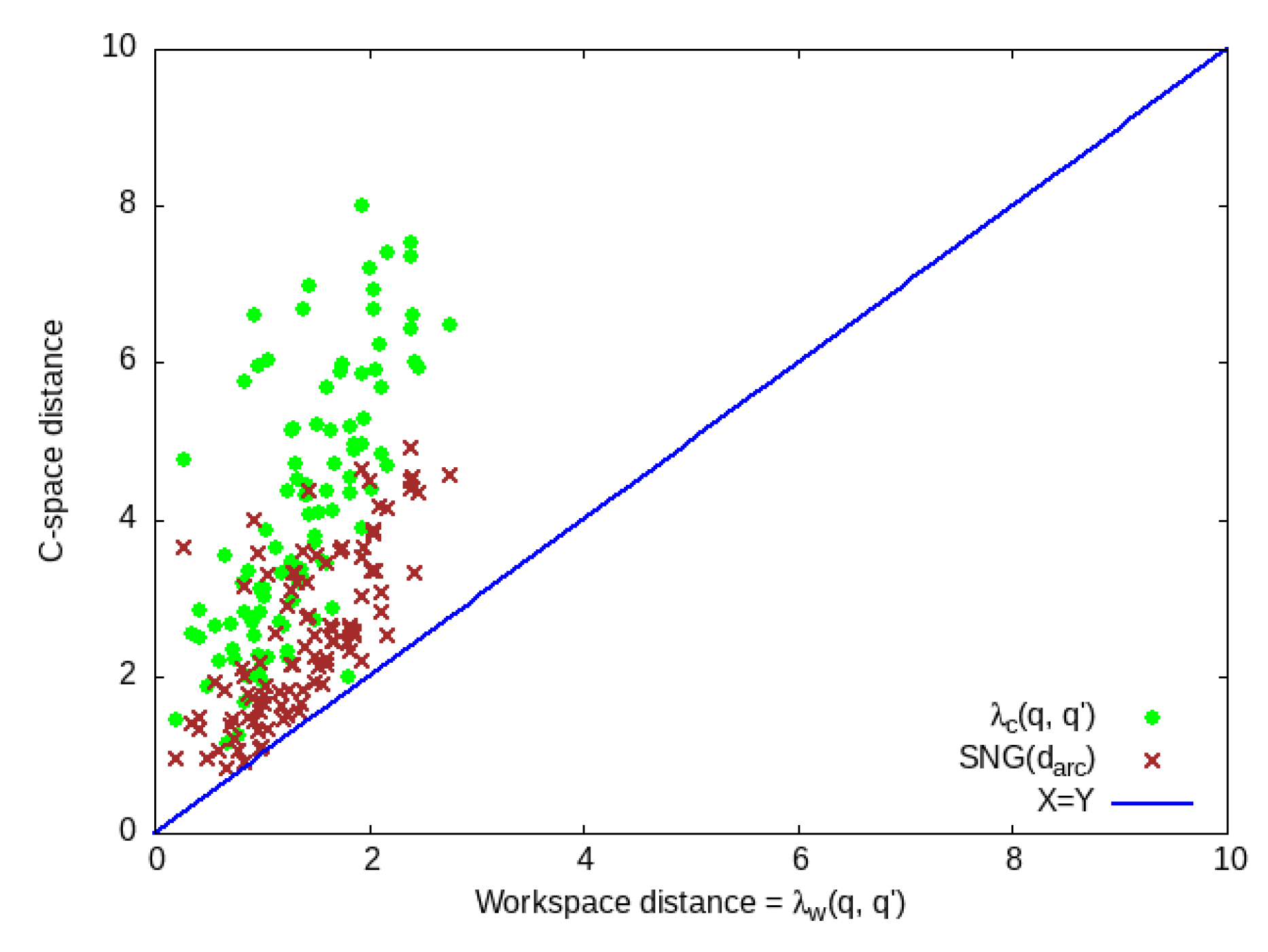

Table 1.
Time and Memory Use Comparison.
| Environment | PRM (baseline) | FVG (ours) | Speedup | Memory | ||||
|---|---|---|---|---|---|---|---|---|
| Nodes | Edges | Time (s) | Nodes | Edges | Time (s) | Reduction | ||
| Pick and Place | ||||||||
| Kitchen | ||||||||
| Workcell | ||||||||
Table 2.
Profiling Collision and Distance Check Time.
| Environment | PRM (baseline) | FVG (ours) | |||||||
| Total collision checks | % time in collision check | Time per collision check | Total collision checks | % time in collision check | Time per collision check | Total distance checks | % time in distance check | Time per distance check | |
| Pick and Place | 2107021 | 99.8 | 0.2 | 86398 | 2.3 | 0.2 | 37314 | 88 | 8.5 |
| Kitchen | 14479186 | 99.9 | 0.8 | 279924 | 7.1 | 0.7 | 126218 | 66 | 6.6 |
| 10109138 | 100 | 0.8 | 392563 | 7 | 0.8 | 164947 | 58.9 | 6.5 | |
| 8271757 | 99.9 | 0.7 | 355818 | 6.5 | 0.7 | 147804 | 57.1 | 6.1 | |
| Workcell | 1076676 | 99.9 | 0.9 | 87353 | 4.7 | 0.9 | 36405 | 92.4 | 17.1 |
| 8569594 | 99.9 | 0.9 | 99862 | 4.1 | 1 | 45922 | 93.2 | 23.4 | |
| 8442970 | 100 | 0.9 | 92801 | 4.1 | 0.9 | 37390 | 94.1 | 20.5 | |
Disclaimer/Publisher’s Note: The statements, opinions and data contained in all publications are solely those of the individual author(s) and contributor(s) and not of MDPI and/or the editor(s). MDPI and/or the editor(s) disclaim responsibility for any injury to people or property resulting from any ideas, methods, instructions or products referred to in the content. |
© 2025 by the authors. Licensee MDPI, Basel, Switzerland. This article is an open access article distributed under the terms and conditions of the Creative Commons Attribution (CC BY) license (http://creativecommons.org/licenses/by/4.0/).
Copyright: This open access article is published under a Creative Commons CC BY 4.0 license, which permit the free download, distribution, and reuse, provided that the author and preprint are cited in any reuse.


