
Submitted:
29 September 2025
Posted:
30 September 2025
You are already at the latest version
Abstract
This paper explores methods of simulating the behaviour of building structures under progressive collapse conditions through alternative models of different levels of structural idealization. Such alternative simulation models have been applied in many previous studies of the problem, but there is insufficient information regarding the degree of reliability and appropriate representation of the actual structural behaviour as the model is simplified by reducing the level of structural idealization. To investigate the problem, the study adopts the alternative load path method through the well-established concept of notional column removal. The study focuses on the interaction of the directly affected structural members with their neighboring structural components. The results demonstrate the significant influence of this parameter on the overall structural response under progressive collapse conditions. Most importantly, it is demonstrated that this parameter depends on many factors and is difficult to quantify without explicitly analyzing the behaviour of the surrounding structure. As a conclusion, a local failure that can potentially lead to progressive collapse should be analyzed in the context of the global behaviour of the structure. Alternatively, effective methods for simulating the boundary conditions of individual structural members should be studied and developed to enable the application of reduced analysis models.
Keywords:
axial restraint
; column removal
; concrete structures
; geometric nonlinearity
; moment capacity
; plastic hinge
; tensile catenary action
1. Introduction
Structural robustness has been a key research topic in the field of structural engineering in recent years [1], as due to the escalating exposure of structures and infrastructures to threats of various origins it has become increasingly imperative to understand their response against accidental extreme actions and to develop appropriate design methods that will ensure an acceptable level of structural safety. The latter is considered sufficient when an extreme load does not cause disproportionate damage to the structure [2]. This can be achieved when the structure is sufficiently robust so that a local damage does not spread progressively, thus leading to a potential disproportionate collapse [3,4,5].
Through intensive research activity over the past decades, the “notional column removal” approach has been established as the most effective method for assessing the response of frame structures to progressive collapse [6,7,8]. This method aims to assess structural redundancy which is a fundamental component of structural robustness of building structures. Structural redundancy is assessed in terms of the ability of the structure to sustain damage of a single load-bearing element, usually through the mobilization of different load-resistance mechanisms and the activation of alternative load paths [9,10] so that a new state of stable equilibrium is achieved to prevent collapse propagation [11].
The column removal approach has been studied extensively in recent decades [12,13,14,15], and it is found in various forms in most current design codes [16,17,18]. Following column removal, the remaining structural components are expected to act as alternative load paths, thus beams and slabs need to compensate for the column failure by transferring its load to the surrounding structure [19,20]. This imposes large deformations that activate additional load-resistance mechanisms in these elements [21,22]. Figure 1 describes the structural behaviour of beams simulated through a double-span mechanism (Figure 1a) that is subject to large vertical displacement at the midspan [14]. In the presence of axial restraint due to the interaction with the surrounding structure, nonlinear geometric effects significantly affect the structural behaviour as they induce the development of axial forces in the beams [23,24]. Of particular importance is the axial tensile force developed at large deformations which may considerably increase the load-carrying capacity as shown in Figure 1b [25,26].
Both beams and slabs [27,28,29], as well as other load bearing and non-bearing elements such as infilled walls [30,31,32] and diagonal bracing systems [33,34], may contribute considerably to structural robustness. Beams usually have a predominant role as they provide resistance through different mechanisms [14,22]. Also, for the mobilization of these mechanisms, the beam-column connections must be able to transfer substantial axial forces in addition to increased bending moments and shear forces whilst undergoing large axial and rotational deformations [35,36]. For these reasons, many studies have focused on understanding the response characteristics of the double-span beam mechanism of Figure 1.
Through the extensive study of the problem, the structural parameters that govern the progressive collapse response of the double-span beam mechanism are now well understood. Based on these parameters, it is therefore possible to determine ways in which the beam response will be enhanced in a column removal scenario [5,22,37]. Where there is still a lack of sufficient knowledge, however, is the interaction between the beams and the surrounding structure [14,24,36]. Understanding this issue is important both for the proper evaluation of the information obtained from previous studies that were restricted to the double-span beam mechanism (experimental, numerical and analytical studies) and the correct application of the column removal approach through representative simulation models that will take into account the effects of interaction with the surrounding structure.
This paper aims to investigate this problem by comparing the results of different structural behaviour simulation models, which represent different levels of structural idealization. Specifically, by applying the notional column removal approach, the feasibility of simulating the progressive collapse response of building structures through reduced simulation models that represent reduced levels of structural idealization is examined. A reinforced concrete frame structure, designed specifically for the purposes of this study, is adopted and a carefully selected column removal scenario is employed. The reduced levels of structural idealization include three-dimensional multiple floor and single floor assemblies, a grillage representation, a two-dimensional plane frame structure, and an isolated double-span beam system. The analysis results of these models are compared with the results of the analysis of the full structure. Therefore, important conclusions are drawn regarding the reliability of such models and the parameters that should be considered when applied to assess the progressive collapse resistance of building structures.
2. Methodology
This section aims to describe the methodology of the study, providing the necessary information regarding the details and characteristics of the structure under consideration (Section 2.1), the modelling approaches employed for simulating the response against progressive collapse based on a carefully selected column removal scenario (Section 2.2), and the analysis methods aimed at drawing specific conclusions in accordance with the objectives of the study (Section 2.3).
2.1. Prototype Structure
For the purposes of the study, a prototype reinforced concrete multi-storey building is considered. The building consists of 8 floors of identical plan layouts as shown in Figure 2. The floor layout is shown in Figure 2a, and the three-dimensional layout of the structure is presented in Figure 2b. The structure type, its layout and the structural details were carefully determined to allow a comprehensive study of the problem under consideration. As shown in Figure 2a, the structure has an almost square plan layout, with a longitudinal dimension of 15 m and a transverse dimension of 15.3 m. The height of each floor is 3 m, so the total height of the 8-storey structure is 24 m plus 3 m of an extended part on the roof.
The building structure was designed against conventional design loads, according to the Eurocode ultimate and serviceability limit state design rules. Structural components, i.e. columns, beams and slabs, are made of C35/45 concrete and steel reinforcing with a yield stress of 500 MPa. Based on the design calculations, the dimensions and properties of the cross-sections of columns, external beams and internal beams were determined as shown in Figure 3a, 3b, and 3c, respectively.
2.2. Modelling Approaches
Previous studies have shown that the structural response to progressive collapse can vary significantly depending on the location of the removed column [9,15,21]. However, it was found that the parameters that influence behaviour are the geometry of the directly affected structure, the structural properties of its constitutive components, and the degree of axial restraint [38,39]. The latter is probably the most influential parameter, as well as the one that is most difficult to quantify [5,36,40]. Taking this data into account and aiming not to extend the study to examining different column removal scenarios, as this would be beyond the scope of the study, only the column removal scenario described in Figure 4 is considered.
The study mainly focuses on the response of the directly affected structural components and in particular the double-span beam mechanism created by beams B1 and B2. According to Figure 4a, the end connections of beam B1 are denoted by C1-1 and C1-2, and the end connections of beam B2 are denoted by C2-1 and C2-2. The lengths of the two beams were chosen to be different (i.e. 5.5 m and 3.0 m respectively) to examine the influence of this parameter. Beams B1 and B2 intersect at joint J2 (Figure 4b), which is defined as the reference node for measuring vertical displacement following column removal.
The structural response is assessed through different modelling approaches based on different levels of structural idealization as shown in Figure 5. In addition to the full structure model (i.e. Model I), four reduced models are analyzed in which appropriate boundary conditions are considered where required. These involve three 3D substructure models (i.e. Models II-IV) and one 2D plane frame model (i.e. Model V). The double-span beam model (i.e. Model VI) that represents the lowest level of structural idealization is also examined. The contribution of the slabs was excluded from all models in order to focus on the behaviour of the beams and thereby enable comparative results.
2.3. Analysis Approach
A nonlinear pushdown analysis [41,42,43] that accounts for large displacements and geometric nonlinearity is performed through the structural analysis program SAP2000. The analysis starts from the unloading stage in the absence of the removed column, and the gravity loading is applied and gradually increased until the load carrying capacity of the structure is exhausted. The structural response is governed by large deformations due to the formation of plastic hinges in beams and columns, and the creation of a plastic collapse mechanism is taken as the failure criterion. The hinge type employed is deformation controlled (ductile) that accounts for moment-axial force interaction effects.
The analysis method enables a step-by-step simulation of structural response, which is representative of a notional column removal scenario [44]. Therefore, performance is traced from the initial unloaded stage up to failure, and a complete set of data on variations in the different structural parameters is obtained. As noted previously, the study focuses mainly on the response of the directly affected beams B1 and B2 and examines how this is described by the different analysis models. The structural response is evaluated based on the following nodal displacements and element joint forces, which are defined in Figure 6:
- Vertical displacement of joint J2, denoted by w.
- Horizontal displacements of joints J1 and J3, denoted by Δ1 and Δ3 respectively.
- Bending moments at the ends of beam B1 (i.e. M1-1 and M1-2) and beam B2 (i.e. M2-1 and M2-2).
- Shear forces at the ends of beam B1 (i.e. V1-1 and V1-2) and beam B2 (i.e. V2-1 and V2-2).
- Axial forces at the ends of beam B1 (i.e. N1-1 and N1-2) and beam B2 (i.e. N2-1 and N2-2).
The beam gravity loading (q) is obtained by considering equilibrium of beam B1 or beam B2, as follows:
Alternatively, the beam gravity loading is determined based on a different equilibrium equation as follows [29]:
Equations (1) and (2) are expected to yield identical results. Moreover, the uniformly distributed gravity loading applied to the two adjacent beams, B1 and B2, should be the same. Finally, the axial forces at the ends of both beams are required to be equal to satisfy equilibrium of the system.
3. Analysis of Full Structure Model
This section presents the results of the analysis of the full structure model (i.e. Model I in Figure 5). Initially, a detailed analysis of the behavior of the directly affected beams B1 and B2 is performed in Section 3.1. Subsequently, Section 3.2 examines the possible influence of the upper floors on the overall response of the structure.
3.1. Response of Beams B1 and B2
The load-deflection response of a single beam is shown in Figure 7. Since the load is considered as uniformly distributed along the beam span, the response is the same for both beam B1 and beam B2, while it is also the same for all the corresponding beams of the upper floors. The curve is representative of the load-deflection response of concrete beams following column removal [15,39,45,46]. That is, at low beam deflections performance is governed by flexural action while the effects of compressive arching action are insignificant. At higher deflections, structural resistance is enhanced by the effects of tensile catenary action.
The structural response of beams B1 and B2 is analyzed in Figure 8. When the connection moment resistances are exhausted (Figure 8a and 8b), the beam tensile force increases considerably as shown in Figure 8c. This causes a reduction in the connection bending moments [46,47] as shown in Figure 8a and 8b. The connection bending moments of beam B1 are slightly different, since performance is influenced by flexural deformation of the beam section [5,29]. The flexural stiffness of the shorter beam B2 is substantially higher, thus the variation in the bending moments of its two end connections is essentially identical. The interaction between the beam axial force and the bending moments of the end connections of the double-span beam is described in Figure 8d.
Figure 8e and 8f show the variation in the axial displacements of the end joints of the double-span beam against the beam axial force and the beam deflection respectively. In both cases, the increase in the axial displacements is highly nonlinear. The curves of Figure 8f confirm that performance is governed by geometric nonlinearity. The curves of Figure 8e demonstrate that the degree of axial restraint changes due to material nonlinearity. These effects are mainly described by the axial displacement of joint J3. The decrease in the slope of this curve indicates that the axial restraint provided by the free edge decreases due to the formation of plastic hinges in the constitutive components (transverse beams and columns). Due to the higher redundancy of the structure in the left end of beam B1, the rate of decrease in the slope of the blue curve is smaller.
3.2. Contribution of the Upper Floors
Figure 9 describes the sequential formation of plastic hinges, focusing for clarity only on the edge plane frame of the structural system. It is observed that plastic hinges have been created at the ends of all directly affected beams from the initial stages of the response. However, the structure continues to maintain and increase its load-carrying capacity, mainly due to the presence of axial tensile force in the beams as well as due to structural redundancy. The same figure depicts the sequential deformation of the structural system. In addition to the vertical displacement due to the loss of the column, the horizontal displacements of the nodes at the right edge of the structure due to the axial forces transferred from the beams to the supports are clearly visible.
However, it is evident from Figure 9 that the relative horizontal displacements of the upper floors are much smaller than those of the first floor. According to Figure 8e and 8f, the horizontal displacements of joints J1 and J3 at the ultimate vertical deflection of 891 mm are equal to 18.5 mm and 188 mm respectively. The horizontal relative displacements of the corresponding joints on the upper floors are given in Figure 10a. The left-side joint displacements decrease with a specific trend. The right-side joint displacements, however, are almost equal and opposite to those of the left side. Firstly, this means that the right-side joints of the upper floors are slightly displaced in the opposite direction relative to joint J3. Secondly, it is shown that the axial deformations of the beams on the upper floors are considerably small, which suggests that the axial forces in these beams are also small.
The latter is confirmed by the axial force-bending moment (N-M) diagrams of the left-side end connections shown in Figure 10b. The dashed grey curve corresponds to connection C1-1, and it is the same as the blue curve of Figure 8d. The remaining curves describe N-M interaction of the corresponding connections on the upper floors. During the elastic stage, the tensile forces of the beams on the upper floors are smaller than the tensile force of beam B1 and in some cases (i.e. 2nd and 8th floors) are even compressive. This results in higher bending moment capacities for the connections of these beams [44,47]. During the plastic stage, these tensile forces increase, but at a much lower rate than beam Β1, reaching much smaller maximum values. Similarly, the connection bending moments exhibit a correspondingly reduced rate of decrease.
The fact that the beam axial force and the connection bending moments are both in the numerator of Equation (2), justifies why the beam load-displacement curves of all floors are the same. However, the beams on the upper floors are governed by different resistance mechanisms, transferring the gravity load mainly through flexural action with a small contribution from tensile catenary action at large displacements. The response of beam B1, on the other hand, is mainly governed by tensile catenary action, with flexural action effects having a limited contribution at large displacements.
4. Analysis of Reduced 3D and 2D Models
The objective is to examine whether the response of building structures following column removal can be simulated through lower levels of structural idealization. Reduced 3D models are examined in Section 4.1, where the level of structural idealization of the structure examined in Section 3 is gradually reduced through appropriate simplifications in the analysis models. A planar 2D model is studied in Section 4.2.
4.1. Three-Dimensional Structural Systems
With respect to Figure 5, the 3D multiple floor system (Model II), the 3D single floor system (Model III), and the 3D grillage system (Model IV) are studied in this section. The analysis models as well as the deformed shapes of the systems along with the distribution of plastic hinges at the plastic collapse limit state are presented in Figure 11.
The structural responses following column removal are described by the curves of Figure 12 – which correspond to the behaviour of the double-span mechanism consisting of beams B1 and B2 – and they are compared with the response of the full structure presented in Figure 8.
4.1.1. Multiple Floor System
In the multiple floor system, only the directly affected multi-storey structural bay and its boundary conditions are considered. The latter parameter is difficult to model accurately, as it must account in a quantitative manner for the degree of axial restraint provided by the surrounding structure. As demonstrated in Section 3, the degree of axial restraint can vary nonlinearly, which makes its quantification even more difficult. Therefore, the modelling approach should be based on some reasonable assumptions. In many previous studies in which reduced analysis models were adopted, the common assumption made is that the degree of axial restraint of a double-span beam is equal to the effective axial stiffness of the adjacent beams [5,29,44]. This assumption is also adopted and examined in this study, so all the beams adjacent to the directly affected structural bay are included in the model as shown in Figure 11a. The interaction of these beams with the neighboring structure, however, is ignored; thus, their end nodes are assumed as simply supported.
Due to the above simplification, the left-hand side is inevitably stiffer against lateral displacement as compared to the full structure model. However, as shown in Figure 8e and 8f, this side was already substantially stiff compared to the other side on the right edge of the structure. Therefore, since the axial displacement of joint J3 is simulated with sufficient accuracy as shown in Figure 12d, it is proven that the overestimation of the axial restraint on the left-hand side is of minor significance. That is, because the beam axial force and the connection bending moments are predicted with reasonable accuracy with respect to the full structure model results, as shown in Figure 12c and 12b respectively. Since the component forces and deformations are accurate, the load-deflection curve is also very similar to the corresponding curve of the full structure model as shown in Figure 12a.
4.1.2. Single Floor System
The single floor system is modelled by reducing the multiple floor system examined in Section 4.1.1 to a single floor sub-assembly with the same boundary conditions along the planar directions, as shown in Figure 11b. The columns of the second floor are also included to simulate boundary conditions, with their top nodes being considered as simply supported. This is a simplified assumption, as the exact resistance of these nodes against horizontal displacement is particularly difficult to determine and simulate quantitatively.
Although the above assumption can be considered conservative as it seems to potentially increase the degree of axial restraint of the right-hand side of the structure, the results shown in Figure 12 prove the opposite. Within the elastic stage, the slope of the red curve in Figure 12d coincides with the slopes of the full structure model and the multiple floor system model. However, the degree of axial restraint decreases rapidly due to the formation of plastic hinges. The reduced degree of structural redundancy of this system plays an important role in this. When plastic hinges are created at the ends of all members connected to joint J3, the resistance of this joint to horizontal displacement is significantly reduced. In the previous models, however, plastic hinges needed to be formed on many more structural members (i.e. mainly the members of the upper floors) for this to happen.
Due to the lower degree of axial restraint, the beam axial force decreases as shown in Figure 12c. However, as the horizontal displacement of joint J3 increases, the columns connected to this joint are subject to axial tension due to geometric nonlinearity. This causes an increase in the degree of axial restraint as shown in Figure 12d and a corresponding increase in the beam axial force as shown in Figure 12c. The high rate of increase in the beam axial force increases considerably the load-carrying capacity of the system at large deflections as shown in Figure 12a. This phenomenon, however, is not representative of the actual structural behaviour.
4.1.3. Grillage System
By eliminating the columns from the single floor model, the system is reduced to a grillage model as depicted in Figure 11c. This model has been adopted in many previous studies [8,9,38,48], mainly because it is the simplest model that may consider 3-dimensional effects. As compared to the higher-level models examined above, however, the resistance against lateral displacements of joint J3 provided by the flexural stiffness of the columns is ignored. Essentially, the only component left to provide lateral resistance is the transverse beam connected to this joint. Since the stiffness of the beams against out-of-plane bending is usually limited, the degree of axial restraint is expected to be relatively small, which is confirmed by the curve shown in Figure 12d.
Therefore, the axial force developed in the beams of the double-span mechanism is limited as shown in Figure 12c, so it has less influence on the reduction of the bending moments of the connections as depicted in Figure 12b. The load-deflection curve is very close to the corresponding curve of the full structure as shown in Figure 12a, but the responses of the two models are governed by different collapse resistance mechanisms. Therefore, a reliable simulation of structural behavior cannot be verified only through the load-deflection curve, but it should also be confirmed that the mechanics of structural behavior are appropriately modelled.
4.2. Multi-Storey Plane Frame
Many experimental and numerical studies usually focus on two-dimensional simulation models to analyze the behavior of frame structures under progressive collapse conditions [31,32,42,49]. This section aims to examine whether an isolated multi-storey plane frame model can simulate the actual response of the structure following notional column removal.
In this case, only the external 8-storey plane frame that includes beams B1 and B2 is considered. The model layout is presented in Figure 13a, where it is shown that it was obtained simply by isolating this frame from the structure without considering any boundary conditions. As a plane frame analysis is applied, the structure cannot undergo out-of-plane deformations. The deformed shape of the system and the distribution of plastic hinges at the plastic collapse limit state are presented in Figure 13b, while the structural behaviour is described by the dashed purple curves of Figure 14. The same figure includes also the corresponding curves of the full structure (i.e. solid grey curves), determined in Section 3.
As compared to the response of the full structure, the plane frame model exhibits a substantially different behaviour, especially at large deflections. This is mainly due to the absence of tensile catenary effects. As shown in Figure 14d, the degree of axial restraint on the right-hand side (i.e. at the edge of the structure) is the same for the two systems as long as the structure behaves elastically. However, a significant decrease occurs in the axial restraint of the plane frame when a plastic hinge is created at the top of the ground floor edge column. Beyond this point, and since the bending stiffness of this element is significantly reduced, there is no additional mechanism available to provide resistance against lateral displacement. For similar reasons, the axial restraint degree of the left-hand side is also reduced, although to a comparatively lesser extent, but this is not illustrated by the curves of Figure 14.
The beam tensile force shows a decreasing trend as shown in Figure 14c, with corresponding effects on the bending moments of the connections which tend to increase (Figure 14b) as the beam deflection increases, instead of decreasing as it happens in the presence of substantial tensile axial force in the beams. In this manner, the system is governed almost exclusively by pure flexural action, with its post-elastic response characterised by a plateau curve as presented in Figure 14a
The only way to modify the model to more effectively simulate the actual behavior is to increase the degree of axial restraint. As also noted in the previous sections, however, a detailed simulation of the degree of axial restraint provided by the surrounding structure is quite challenging, especially as it depends on a combination of parameters and varies nonlinearly with the successive creation of plastic hinges in the various components. Even if an approximate value of the degree of axial restraint is quantified and simulated using elastic supports to maintain the simplicity of the model, nonlinear behavior cannot be taken into account.
The above simplified solution is examined herein in two steps. First, an approximate value of the degree of axial restraint provided to the right-hand side of the structure is calculated. For joint J3, this value is taken as the post-limit slope of the red curve in Figure 8e, determined through linear regression. Similarly, the degree of axial restraint provided to all corresponding nodes of the upper floors is calculated based on the relevant curves obtained from the analysis of the full structure. On average, it was calculated that the degree of axial restraint is approximately equal to 2030 kN/m. Therefore, in a new model, linear springs of axial stiffness equal to this value are introduced at all nodes on the right-hand side.
As described by the red dashed curves of Figure 14, this modification has an impact on the behaviour, but it still does not satisfactorily approximate the response of the full structure. In the same manner as described above, the average value of the degree of axial restraint provided at the joints of the left-hand side (i.e. joint J1 and corresponding joints of upper floors) was calculated to be equal to approximately 20150 kN/m. By introducing a set of linear springs of axial stiffness equal to this value at all nodes on the left-hand side, the behaviour is modified as described by the green dashed curves of Figure 14. As in the case of the grillage system, the load-deflection curve resembles closely the corresponding curve of the full structure, but it is observed that the component forces are quite different. It is concluded that the simulation of the behaviour through a simplified 2-dimensional model is limited by insufficient representation of the axial restraint provided by the surrounding structure.
5. Double-Span Beam System
Although several limitations that may arise in the simulation of structural behavior through lesser levels of structural idealization have already been identified in the previous section, it is worth examining as a final case the double-span beam system in isolation. It is easily understood that this system cannot be examined without the consideration of appropriate boundary conditions simulating axial restraint on either side of the double-span beam structure, as then the behavior will be governed only by flexural action. Therefore, boundary conditions are introduced in the model through two approaches. In Section 5.1, the axial restraint is simulated by linear springs with appropriate axial stiffness. Through a more detailed approach, Section 5.2 examines the case of the change in the axial stiffness of the supports using bi-linear link elements. The layout of the model and the typical form of the deformed shape at the plastic collapse limit state are shown in Figure 15.
5.1. Simulation of Axial Restraint Through Linear Springs
Many studies on the progressive collapse of structures focus on the double-span beam mechanism [4,13,15,45]. To enable the mobilization of compressive arching and tensile catenary actions, particular importance is given in these studies to ensure an appropriate degree of axial restraint. In the absence of specific information, an approximation is usually made regarding this parameter, and a degree of axial restraint is determined based on assumptions and simple estimates. In most cases, the degree of axial restraint is approximated through a single value of axial stiffness, representing the resistance of the supports to elastic horizontal displacements.
Based on this consideration, the possibility of accurately approximating the degree of axial restraint in a double-span beam through linear springs is studied herein. There are two issues in this problem, as there is obviously the question – as demonstrated in the previous sections – whether the axial supports behave elastically as well as whether the value of the axial stiffness they provide can be easily estimated. Regarding the second issue, as the results of the analysis of the full structure are available (see Section 3), they will be used to determine the value of axial stiffness.
The same approach is adopted as in the plane frame of Section 4.2, thus the stiffness on either side of the double-span beam is taken as the slope of the post-limit parts of the curves of Figure 8e. Since only the first floor is considered, the values of axial stiffness are larger compared to the plane frame simulation, and specifically they are equal to 27200 kN/m and 3550 kN/m, respectively. The results of the analysis are presented in Figure 16, and they are compared with the corresponding results of the full structure. As in some of the cases examined in Section 4, a seemingly representative simulation of the behaviour is obtained through the load-deflection curve in Figure 16a, but this is not confirmed by the component forces presented in Figure 16b and 16c.
The difference in the connection bending moments is mainly due to the difference in the beam axial force, since the latter is considerably underestimated due to the assumption made about the axial restraint degree. The results shown in Figure 16d align with that assumption, as the curves corresponding to the double-span beam idealization are parallel to the post-limit parts of the curves corresponding to the full structure. The high initial value of the axial stiffness of the supports, however, which causes a significant and rapid increase in the axial tensile force of the beams at small deflections is not taken into account. Thus, it is confirmed that the nonlinear variation of the horizontal displacement of the supports with respect to the increase in the beam axial force significantly affects the behaviour.
5.2. Simulation of axial Restraint Through Bi-Linear Links
Provided the characteristics of the nonlinear behaviour of the supports are known, which of course in practice can hardly be the case, a more sophisticated approach can be adopted for simulating performance. The curves in Figure 8e describe an almost bi-linear force-deformation relationship. Therefore, the linear springs of the model of Section 5.1 are replaced herein by bi-linear links with their characteristics defined according to the curves of Figure 8e. The analysis results are shown in Figure 17, and they are compared again with the results of the full structure model.
Figure 17d confirms that the force-deformation responses of the supports are now represented with sufficient accuracy compared to the full structure model. For this reason, the variation of the beam axial force is also more accurate as shown in Figure 17c. Consequently, the variation of the connection bending moments is described more correctly compared to the model of Section 5.1, but at large deformations significant deviations are still observed according to Figure 17b. These deviations have a significant impact on the load-deflection curve as shown in Figure 17a.
The significant difference between the bending moments of the connections calculated by the two models indicates that the double-span beam system behaves differently. These results show that the degree of axial restraint is not the only boundary condition that significantly affects structural behavior. The other boundary condition is the rotational stiffness of the support joints J1 and J3. In addition to the elastic and plastic rotations of the connections, the structural joints undergo additional rigid-body rotations. This effect, however, can only be described by the full structure model, as the support joints J1 and J3 have been modeled as rigid in terms of rotation in the simplified double-span beam model.
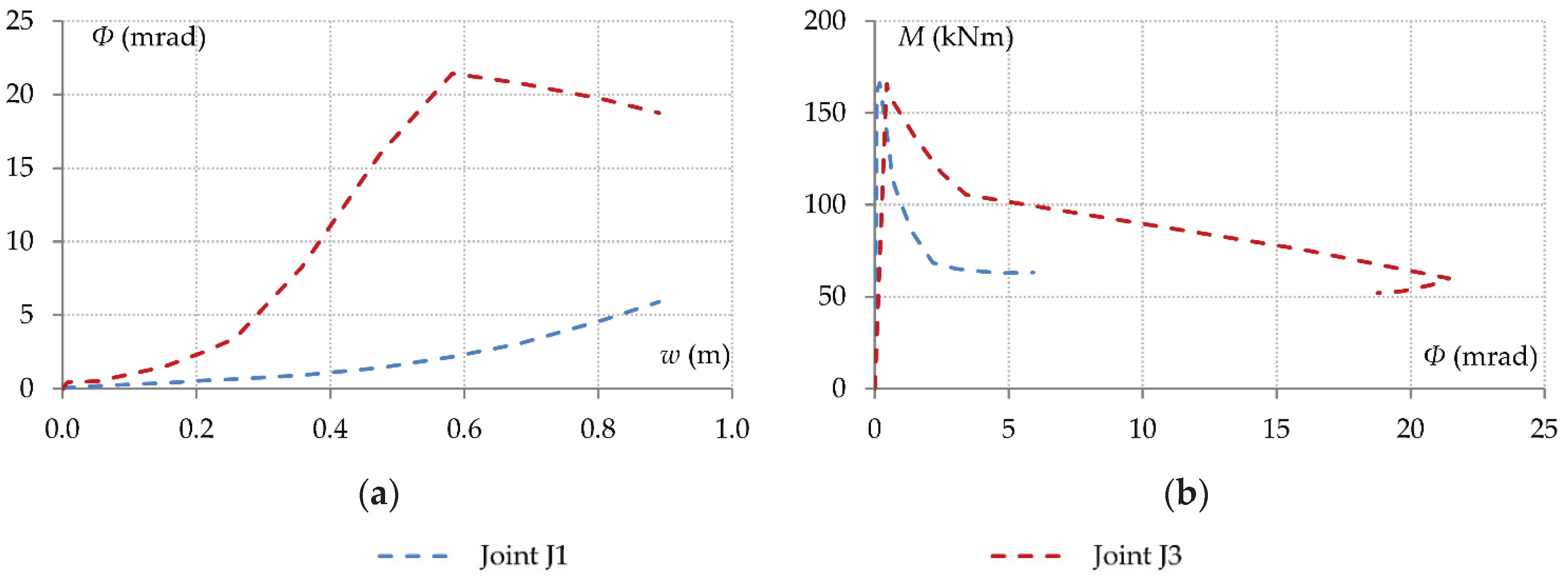
Further modification of the characteristics of the supports to take into account the deformability of the joints is extremely difficult to implement. On the one hand, it is almost impossible in practice to predict these rotational deformations. On the other hand, the rotations of the joints depend on how the load is redistributed to the various members as the stiffness of the elements connected at these joints decreases. The changes in the rotations (Φ) of joints J1 and J3 of the full structure model with respect to the beam displacement are presented in Figure 18a. It is observed that these curves are neither linear nor monotonic.
The corresponding relationships between the bending moments of the connections included in these joints and the joint rotations are presented in Figure 18b. The curves confirm that these rotations are independent of the corresponding moments transferred by beams B1 and B2 respectively, so they depend largely on the interaction with the structural components of the surrounding structure. Such interaction effects, however, can only be described by the full structure model, or by reduced models of a sufficient level of structural idealization such as, for example, the 3D multiple storey system examined in Section 4.
6. Conclusions
Through this study, it was sought to examine the possibility of simulating the progressive collapse behavior of frame structures through different analysis models that represent different levels of structural idealization. The characteristics of the structure under consideration as well as the method of analyzing structural behaviour through a specific notional column removal scenario were carefully determined so that useful conclusions could be drawn in accordance with the objectives of the study. In addition to the overall structure model, simplified three-dimensional and two-dimensional models were analyzed, as well as the double-span beam model, which essentially represents the lower possible level of structural idealization for progressive collapse analysis.
The main conclusions of the study are as follows:
- The axial displacement of the supports of the system that is directly affected by the column loss is influenced by material nonlinearity due to formation of plastic hinges in neighboring structural elements. For this reason, the variation in the support axial displacements with respect to the axial force transferred from the end connections is highly nonlinear. The degree of axial restraint is also governed by the redundancy of the structure on either side of the directly affected area, as well as on the out-of-plane flexural stiffness of the transverse beams and the in-plane bending stiffness of the surrounding columns.
- In a ground-floor column removal scenario, the ground-floor neighboring columns are subject to considerably higher bending moments and deformations due to their support boundary restraints, as compared to the columns of the upper floors. For this reason, the axial forces developed in the beams of the upper floors are substantially smaller than the axial force developed in the beams of the first floor. Therefore, the responses of the beams of different floors are governed by very different load-resistance mechanisms.
- A 3D multiple floor model can describe performance with reasonable accuracy. A 3D single floor model, on the other hand, is not sufficient to describe the effects of axial restraint accurately. The resistance of the supports to horizontal displacement decreases significantly when the strength of the neighboring elements is exhausted. At large deformation stages, however, the support axial stiffness increases due to geometric nonlinear effects, which is not representative of the actual structural behaviour. In a grillage model, a reasonable approximation of the load-deflection response was obtained in this study, but it was shown that this resulted from an inaccurate representation of the contribution from the different load resistance mechanisms.
- Plane frame models cannot simulate the boundary conditions sufficiently. Key elements of the surrounding structure such as the transverse beams are not taken into account. The representation of axial restraint through linear elastic springs will most likely lead to incorrect results, as the axial deformation of the supports varies nonlinearly. This approximation may also result in incorrect assessment of the contribution of the different load resistance mechanisms, similar to the comment made above about the grillage system.
- In the double-span beam model, the degree of axial restraint should be simulated with sufficient accuracy. Since the resistance provided by the supports against horizontal displacements varies nonlinearly with respect to the increase in the beam tensile force, linear elastic springs cannot describe the boundary conditions sufficiently. Instead, by employing suitable links with bi-linear force-deformation characteristics a more representative approximation is obtained. However, it is found that, although the beam axial force is described accurately, the connection bending moments exhibit deviations from the actual values. This shows that another parameter that influences the progressive collapse response is the rotational stiffness provided to the support joints from the surrounding structure.
Based on the above observations, it is concluded that in a progressive collapse analysis either the full structure should be considered, or at least a reduced model such as the multiple floor system that explicitly accounts for the axial and rotational stiffness of the supports. For lesser levels of structural idealization, suitable boundary conditions should be applied. This is however quite challenging, as appropriate values for the axial and rotational stiffness of the supports are difficult to determine, while both parameters vary highly nonlinearly. Consequently, it is demonstrated that this aspect of the problem requires more study and better understanding. As future work, detailed finite element models will be developed, considering similar boundary conditions, through the use of advanced finite element analysis (FEA) software, in order to further investigate the distribution of plastic stresses and plastic strains and to explore effective simulation strategies.
Author Contributions
Conceptualization, T.K.M. and P.M.S.; methodology, T.K.M. and P.M.S.; formal analysis, T.K.M., P.M.S.; investigation, T.K.M., P.M.S. and A.I.I.; resources, T.K.M., P.M.S. and A.I.I.; data curation, P.M.S. and A.I.I.; writing—original draft preparation, P.M.S.; writing—review and editing, T.K.M. and A.I.I.; supervision, P.M.S. and A.I.I.; project administration, P.M.S. All authors have read and agreed to the published version of the manuscript.
Funding
This research received no external funding.
Data Availability Statement
The original contributions presented in this study are included in the article. Further inquiries can be directed to the corresponding author.
Conflicts of Interest
The authors declare no conflict of interest.
References
- Elkady, N.; Nelson, L.A.; Weekes, L.; Makoond, N.; Buitrago, M. Progressive collapse: Past, present, future and beyond. Structures 2024, 62, 106131. [Google Scholar] [CrossRef]
- Nair, S.R. Preventing disproportionate collapse. J. Perform. Constr. Facil. 2006, 20, 309–314. [Google Scholar] [CrossRef]
- Starossek, U. Progressive Collapse of Structures; Thomas Telford: London, UK, 2009. [Google Scholar]
- Nethercot, D.A.; Stylianidis, P.; Izzuddin, B.A.; Elghazouli, A.Y. Enhancing the robustness of steel and composite buildings. Adv. Steel Constr. 2011, 7(1), 64–85. [Google Scholar]
- Stylianidis, P.; Nethercot, D. Considerations for robustness in the design of steel and composite frame structures. Struct. Eng. Int. 2017, 27, 263–280. [Google Scholar] [CrossRef]
- Gudmundsson, G.V.; Izzuddin, B.A. The ‘sudden column loss’ idealisation for disproportionate collapse assessment. Struct. Eng. 2010, 88, 22–26. [Google Scholar]
- Yu, J.; Tan, K.H. Structural behavior of RC beam-column subassemblages under a middle column removal scenario. J. Struct. Eng. 2013, 139(2), 233–250. [Google Scholar] [CrossRef]
- Lim, N.S.; Tan, K.H.; Lee, C.K. Experimental studies of 3D RC substructures under exterior and corner column removal scenarios. Eng. Struct. 2017, 150, 409–427. [Google Scholar] [CrossRef]
- Stylianidis, P.M. , Nethercot, D.A.; Izzuddin, B.A.; Elghazouli, A.Y. Robustness assessment of frame structures using simplified beam and grillage models. Eng. Struct. 2016, 115, 78–95. [Google Scholar]
- Shan, S.; Wang, H.; Li, S.; Wang, B. Evaluation of progressive collapse resistances of RC frame with contributions of beam, slab and infill wall. Structures 2023, 53, 1463–1475. [Google Scholar] [CrossRef]
- Stylianidis, P.M; Nethercot, D.A.; Izzuddin, B.A.; Elghazouli, A.Y. Progressive collapse: Failure criteria used in engineering analysis. In Proceedings of the 2009 Structures Congress, Austin, TX, USA, 30 April–2 May 2009; ASCE: New York, NY, USA, 2009; pp. 1811–1820. [Google Scholar]
- Yi, W.-J.; He, Q.-F.; Xiao, Y.; Kunnath, S.K. Experimental study on progressive collapse-resistant behavior of reinforced concrete frame structures. ACI Struct. J. 2008, 105(4), 433–439. [Google Scholar] [CrossRef]
- Yu, J.; Tan, K.H. Experimental and numerical investigation on progressive collapse resistance of reinforced concrete beam column sub-assemblages. Eng. Struct. 2013, 55, 90–106. [Google Scholar] [CrossRef]
- Stylianidis, P.M.; Nethercot, D.A.; Izzuddin, B.A.; Elghazouli, A.Y. Modelling of beam response for progressive collapse analysis. Structures 2015, 3, 137–152. [Google Scholar] [CrossRef]
- Pham, A.T.; Cao, D.K. Numerical and simplified analytical investigation on RC frame behaviours under progressive collapse scenarios. Structures 2022, 44, 880–892. [Google Scholar] [CrossRef]
- EN 1991-1-7, Eurocode 1: Actions on Structures – Part 1-7: General Actions – Accidental Actions, Brussels; 2006.
- GSA (General Services Administration), Alternate Path Analysis and Design Guidelines for Progressive Collapse Resistance, Washington, D.C., USA; 2016.
- DoD (Department of Defense), Unified Facilities Criteria-Design of Buildings to Resist Progressive Collapse, Washington, D.C., USA; 2016.
- Qian, K.; Li, B. Performance of three-dimensional reinforced concrete beam column substructures under loss of a corner column scenario. J. Struct. Eng. 2013, 139(4), 584–594. [Google Scholar] [CrossRef]
- Li, B.; Zhu, Y.; Wang, W.; Gu, L. A three-dimensional analytical framework for progressive collapse response of RC frames under column loss scenario. J. Build. Eng. 2025, 106, 112608. [Google Scholar] [CrossRef]
- Sagiroglu, S.; Sasani, M. Progressive collapse-resisting mechanisms of reinforced concrete structures and effects of initial damage locations. J. Struct. Eng. 2014, 140(3), 04013073. [Google Scholar] [CrossRef]
- Stylianidis, P.M.; Nethercot, D.A.; Izzuddin, B.A.; Elghazouli, A.Y. Study of the mechanics of progressive collapse with simplified beam models. Eng. Struct. 2016, 117, 287–304. [Google Scholar] [CrossRef]
- Lim, N.S.; Tan, K.H.; Lee, C.K. Effects of rotational capacity and horizontal restraint on development of catenary action in 2-D RC frames. Eng. Struct. 2017, 153, 613–627. [Google Scholar] [CrossRef]
- Tan, Z.; Zhong, W.-H.; Meng, B.; Zheng, Y.-H.; Duan, S.-C. Effect of various boundary constraints on the collapse behavior of multi-story composite frames. J. Build. Eng. 2022, 52, 104412. [Google Scholar] [CrossRef]
- Nethercot, D.A.; Stylianidis, P.; Izzuddin, B.A.; Elghazouli, A.Y. Resisting progressive collapse by the use of tying resistance. In Steel and Composite Structures; Uy, B., Ed.; Research Publishing: London, UK, 2010; pp. 94–109. [Google Scholar]
- Nethercot, D.A.; Stylianidis, P. Utilising catenary action as a method for resisting progressive collapse. In Advances in Steel and Aluminium Structures; Hieng, H.L., Ed.; Research Publishing: London, UK, 2011; pp. 22–28. [Google Scholar]
- Qian, K.; Li, B. Slab effects on response of reinforced concrete substructures after loss of corner column. ACI Struct. J. 2012, 109(6), 845–855. [Google Scholar] [CrossRef]
- Keyvani, L.; Sasani, M.; Mirzaei, Y. Compressive membrane action in progressive collapse resistance of RC flat plates. Eng. Struct. 2014, 59, 554–564. [Google Scholar] [CrossRef]
- Stylianidis, P.M.; Nethercot, D.A. Simplified methods for progressive collapse assessment of frame structures. J. Struct. Eng. 2021, 147(11), 04021183. [Google Scholar] [CrossRef]
- Shan, S.; Li, S.; Wang, S. Effect of infill walls on mechanisms of steel frames against progressive collapse. J. Constr. Steel Res. 2019, 162, 105720. [Google Scholar] [CrossRef]
- Qu, T.; Zeng, B.; Zhou, Z.; Huang, L.; Chang, D. Progressive collapse resistance of prestressed concrete frame structures with infill walls considering instantaneous column failure. Struct. Des. Tall Spec. Build. 2024, 33(18), e2175. [Google Scholar] [CrossRef]
- Moran, J.G.P.; de Oliveira, I.X.; Shauer, N.; Oliveira, H.L.; Siqueira, G.H. Comparison of displacement-based and force-based formulations for modeling collapse of infill and bare frames. J. Build. Eng. 2025, 113, 113923. [Google Scholar] [CrossRef]
- Qian, K.; Lan, X.; Li, Z.; Fu, F. Effects of steel braces on robustness of steel frames against progressive collapse. J. Struct. Eng. 2021, 147, 04021180. [Google Scholar] [CrossRef]
- Jadallah, M.; Almustafa, M.K.; Dogangün, A.; Nehdi, M.L. Performance of X and inverted V bracing systems in controlling progressive collapse of reinforced concrete buildings. Results Eng. 2025, 27, 105812. [Google Scholar] [CrossRef]
- Stylianidis, P.; Nethercot, D.A. Representation of connection behaviour for progressive collapse response. Int. J. Struct. Eng. 2010, 1, 340–360. [Google Scholar] [CrossRef]
- Stylianidis, P.; Bellos, J. Survey on the role of beam-column connections in the progressive collapse resistance of steel frame buildings. Buildings 2023, 13, 1696. [Google Scholar] [CrossRef]
- Azim, I.; Yang, J.; Bhatta, S.; Wang, F.; Liu, Q.F. Factors influencing the progressive collapse resistance of RC frame structures. J. Build. Eng. 2020, 100986. [Google Scholar] [CrossRef]
- Zolghadr Jahromi, H.; Vlassis, A.G.; Izzuddin, B.A. Modelling approaches for robustness assessment of multi-storey steel-composite buildings. Eng. Struct. 2013, 51, 278–294. [Google Scholar] [CrossRef]
- Senderovich, S.; Brodsky, A. Numerical analysis of RC frames under column removal: A review of current methods and development of a reduced-order approach. J. Build. Eng. 2025, 108, 112847. [Google Scholar] [CrossRef]
- Huanga, H.; Huang, M.; Zhang, W.; Guo, M.; Liu, B. Progressive collapse of multistory 3D reinforced concrete frame structures after the loss of an edge column. Struct. Infrastruct. Eng. 2022, 18(2), 249–265. [Google Scholar] [CrossRef]
- Marjanishvili, S.; Agnew, E. Comparison of various procedures for progressive collapse analysis. J. Perform. Constr. Facil. 2006, 20, 365–374. [Google Scholar] [CrossRef]
- Khandelwal, K.; El-Tawil, S. Pushdown resistance as a measure of robustness in progressive collapse analysis. Eng. Struct. 2011, 33, 2653–2661. [Google Scholar] [CrossRef]
- Vinay, M.; Rao, P.K.R.; Dey, S.; Swaroop, A.H.L.; Sreenivasulu, A.; Rao, K.V. Evaluation of progressive collapse behavior in reinforced concrete buildings. Structures 2022, 45, 1902–1919. [Google Scholar] [CrossRef]
- Stylianidis, P. Progressive Collapse Response of Steel and Composite Buildings. Ph.D. Thesis, Department of Civil and Environmental Engineering, Imperial College London, London, UK, 2011. [Google Scholar]
- Fu, Q.-L.; Tan, L.; Long, B.; Kang, S.-B. Numerical investigations of progressive collapse behaviour of multi-storey reinforced concrete frames. Buildings 2023, 13, 533. [Google Scholar] [CrossRef]
- Long, X.; Iyela, P.M.; Su, Y.; Atlaw, M.M.; Kang, S.-B. Numerical predictions of progressive collapse in reinforced concrete beam-column sub-assemblages: A focus on 3D multiscale modeling. Eng. Struct. 2024, 315, 118485. [Google Scholar] [CrossRef]
- Stylianidis, P.M.; Nethercot, D.A. Modelling of connection behaviour for progressive collapse analysis. J. Constr. Steel Res. 2015, 113, 169–184. [Google Scholar] [CrossRef]
- Elkholy, S.; Shehada, A.; El-Ariss, B. Innovative scheme for RC building progressive collapse prevention. Eng. Fail. Anal. 2023, 154, 107638. [Google Scholar] [CrossRef]
- Savin, S.; Kolchunov, V.; Fedorova, N.; Tuyen Vu, N. Experimental and numerical investigations of RC frame stability failure under a corner column removal scenario. Buildings 2023, 13, 908. [Google Scholar] [CrossRef]
Figure 1.
Beam response following column removal: (a) Representation of double-span beam mechanism; (b) Beam load-deflection response.
Figure 1.
Beam response following column removal: (a) Representation of double-span beam mechanism; (b) Beam load-deflection response.
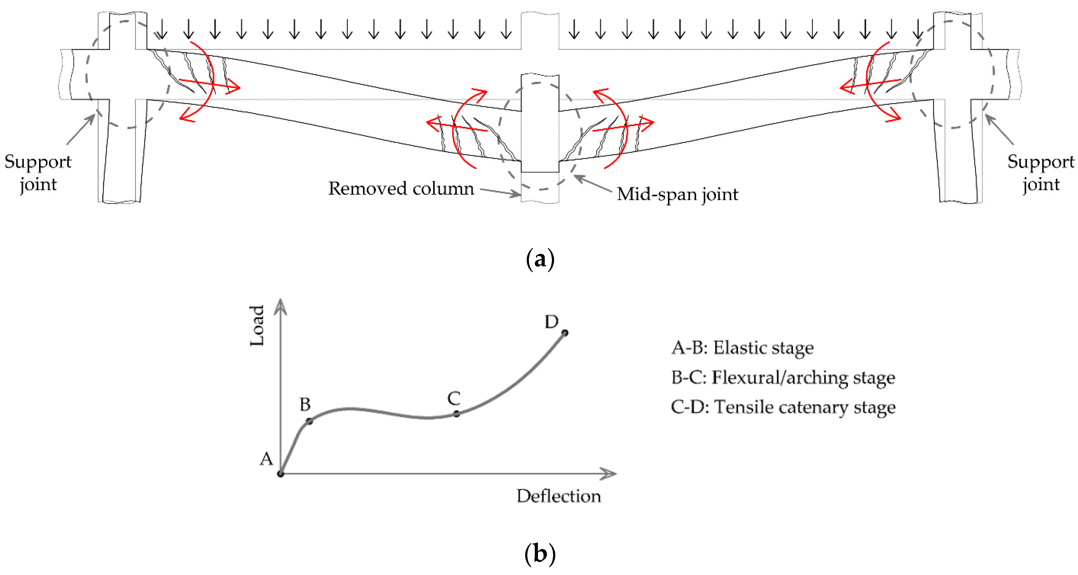
Figure 2.
Geometry of building structure: (a) Floor plan layout; (b) Three-dimensional layout.

Figure 3.
Cross sections of structural components (dimensions in mm): (a) Columns; (b) External beams; (c) Internal beams.
Figure 3.
Cross sections of structural components (dimensions in mm): (a) Columns; (b) External beams; (c) Internal beams.
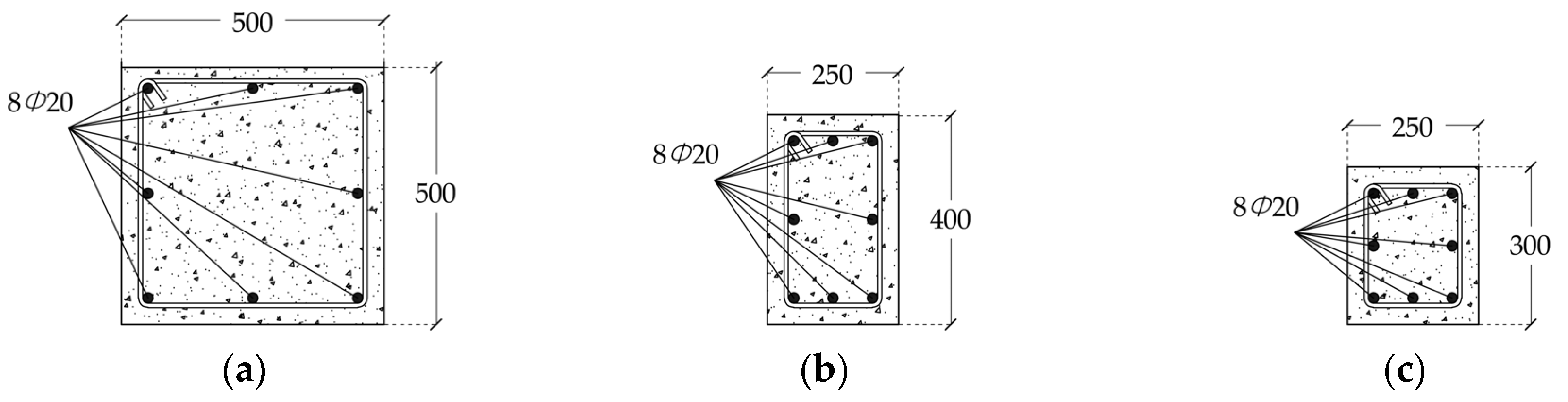
Figure 4.
Column removal scenario and directly affected structural components: (a) Planar view; (b) Three-dimensional view.
Figure 4.
Column removal scenario and directly affected structural components: (a) Planar view; (b) Three-dimensional view.
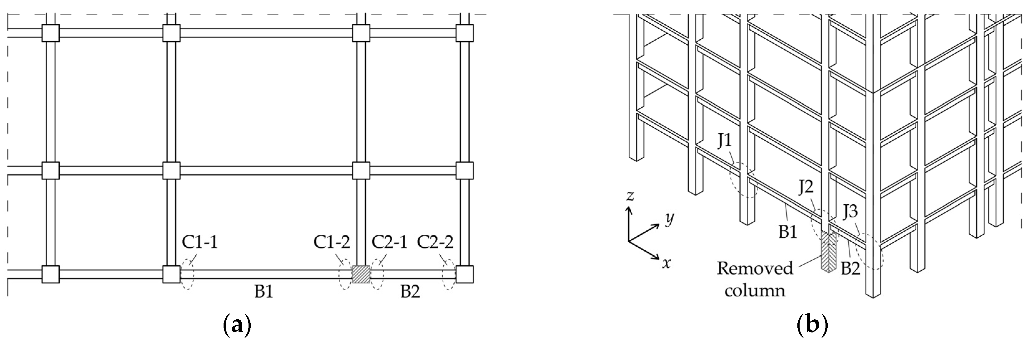
Figure 5.
Modelling approaches based on different levels of structural idealization.
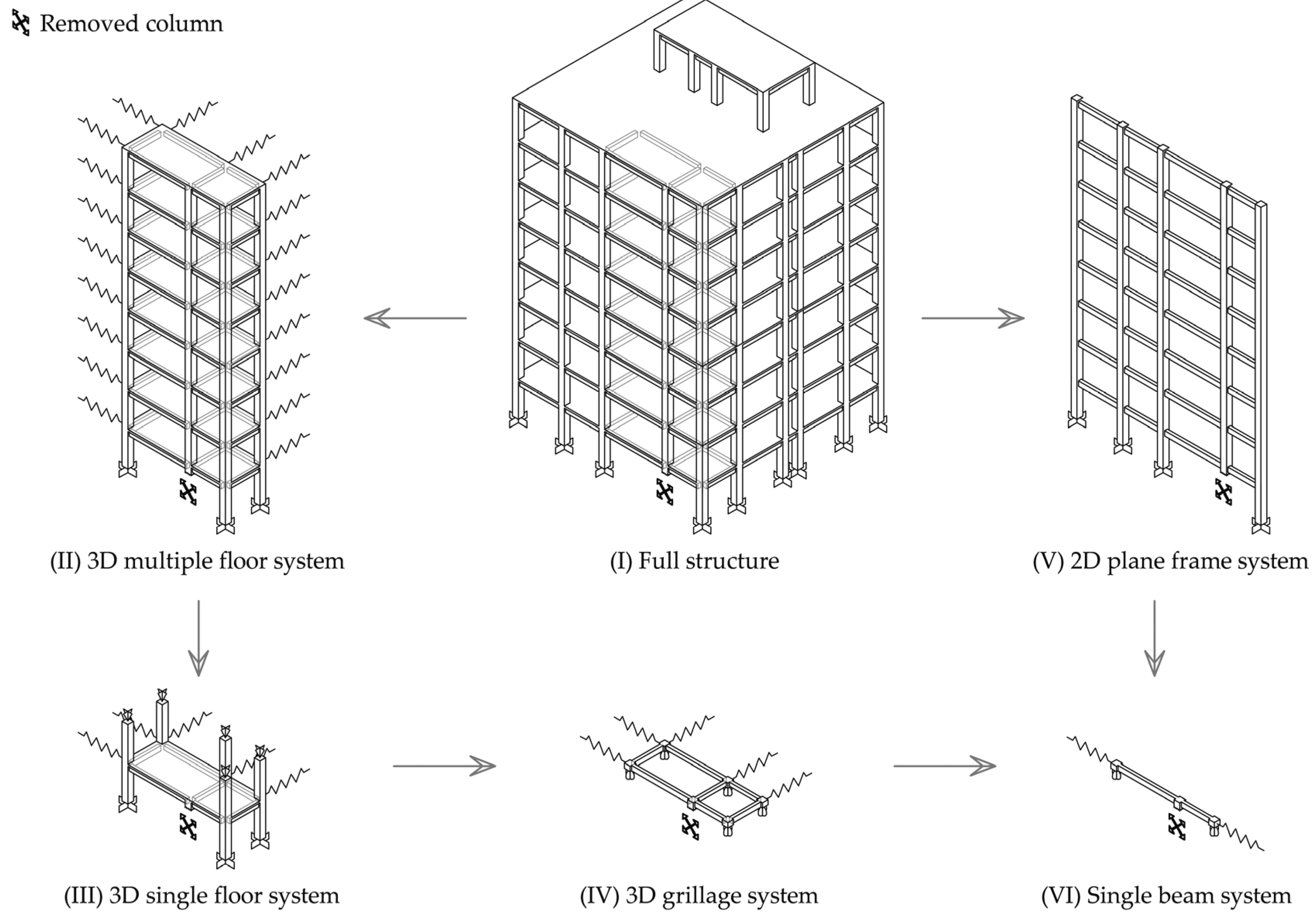
Figure 6.
Component forces and deformations of the double-span beam system.
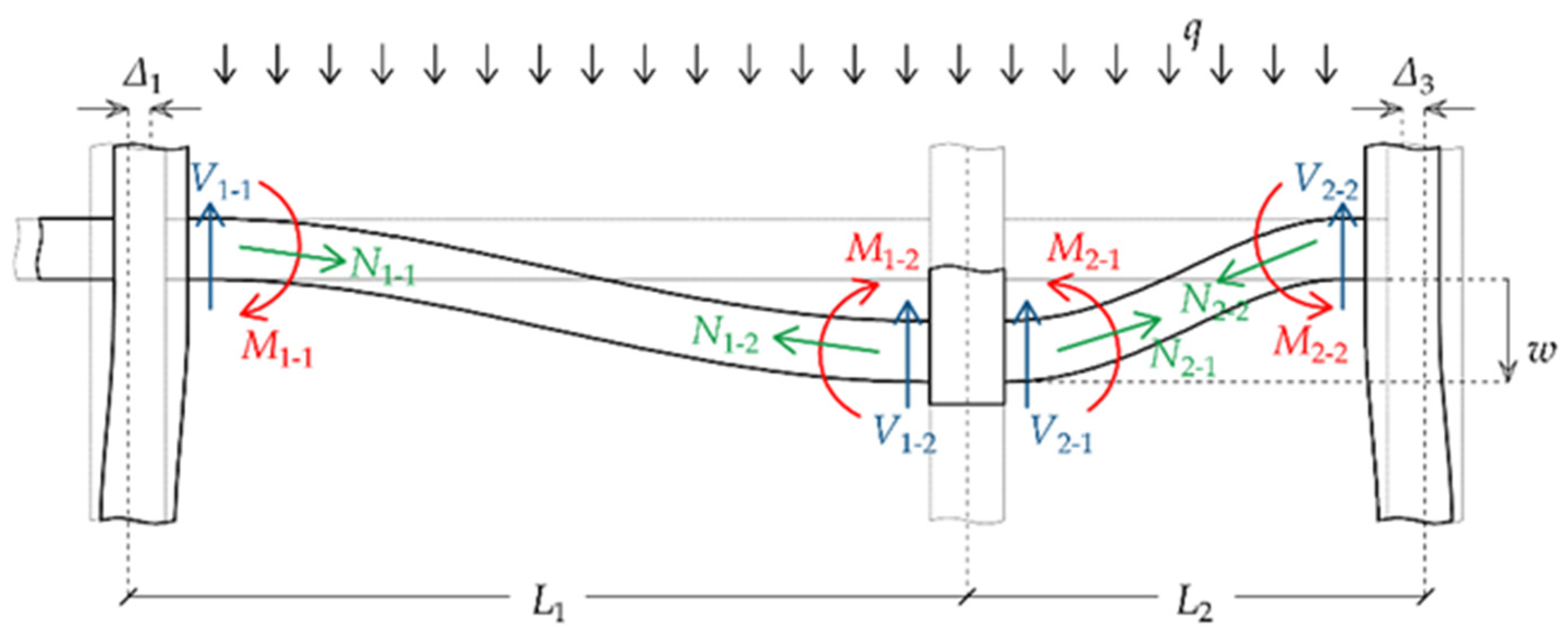
Figure 7.
Beam load-deflection response obtained from the full structure model.
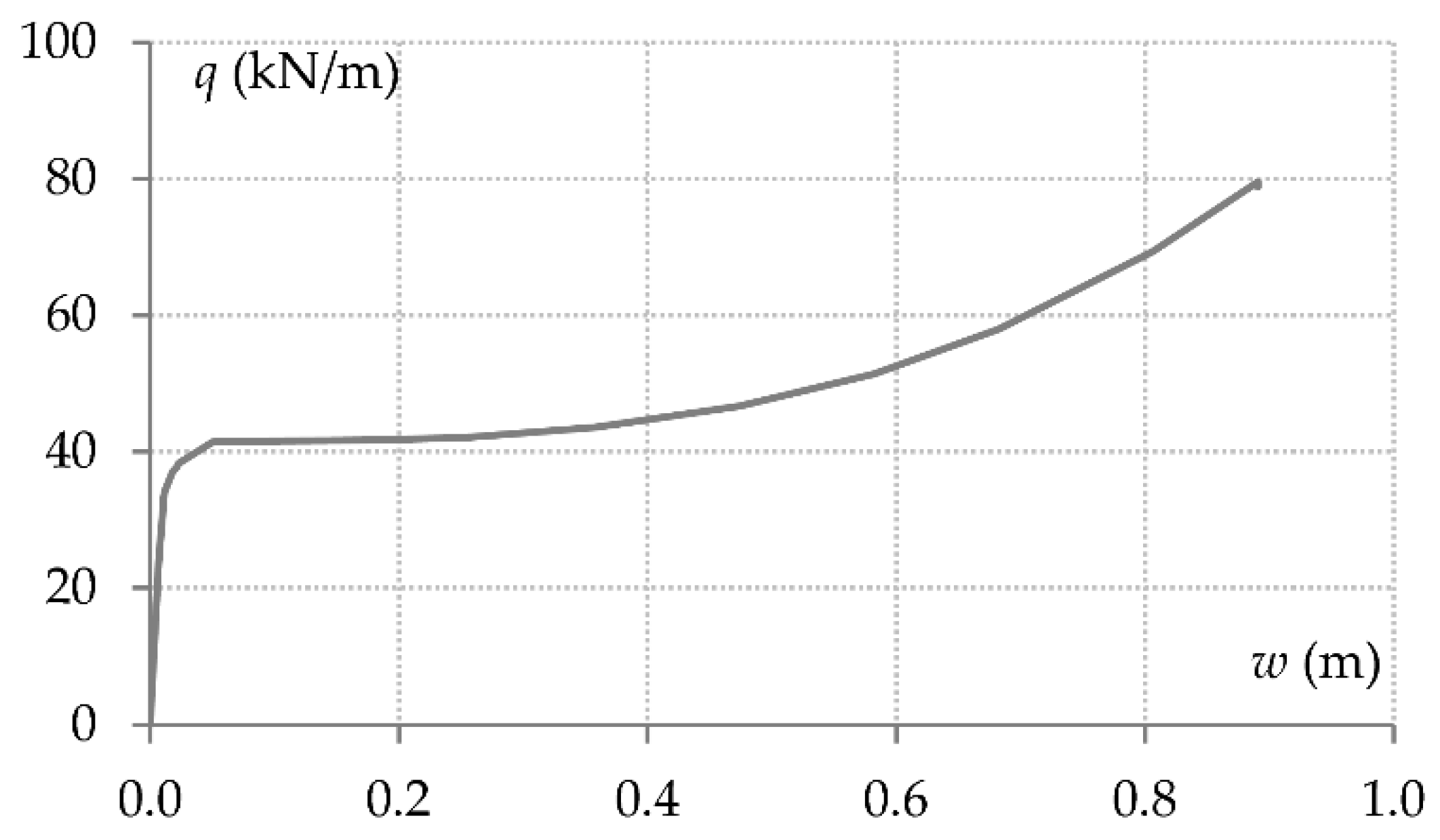
Figure 8.
Component response characteristics of full structure model: (a) End moments of beam B1; (b) End moments of beam B2; (c) Beam axial force; (d) Axial force-bending moment interaction of end connections; (e) Axial displacements of end joints vs. beam axial force; (f) Axial displacements of end joints vs. beam deflection.
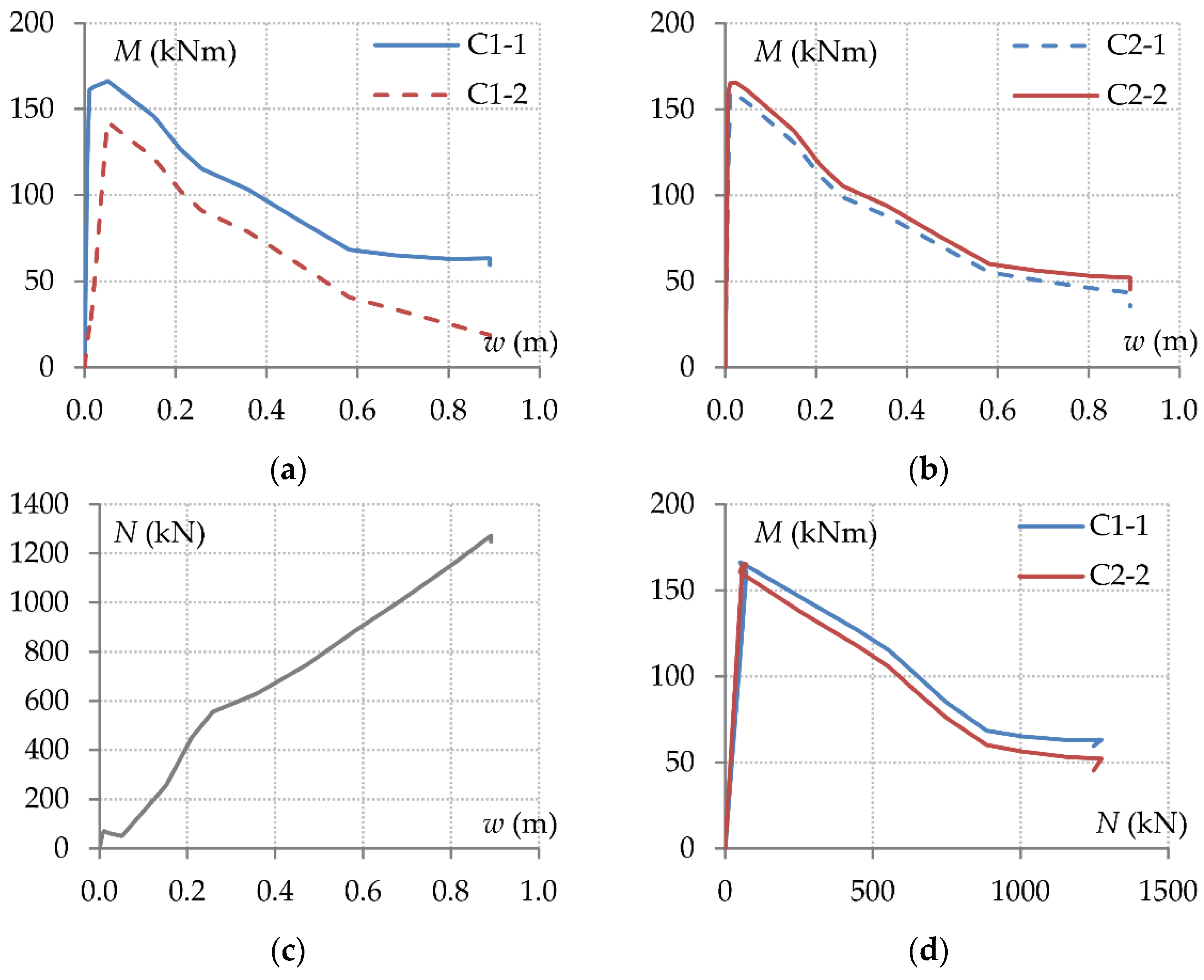
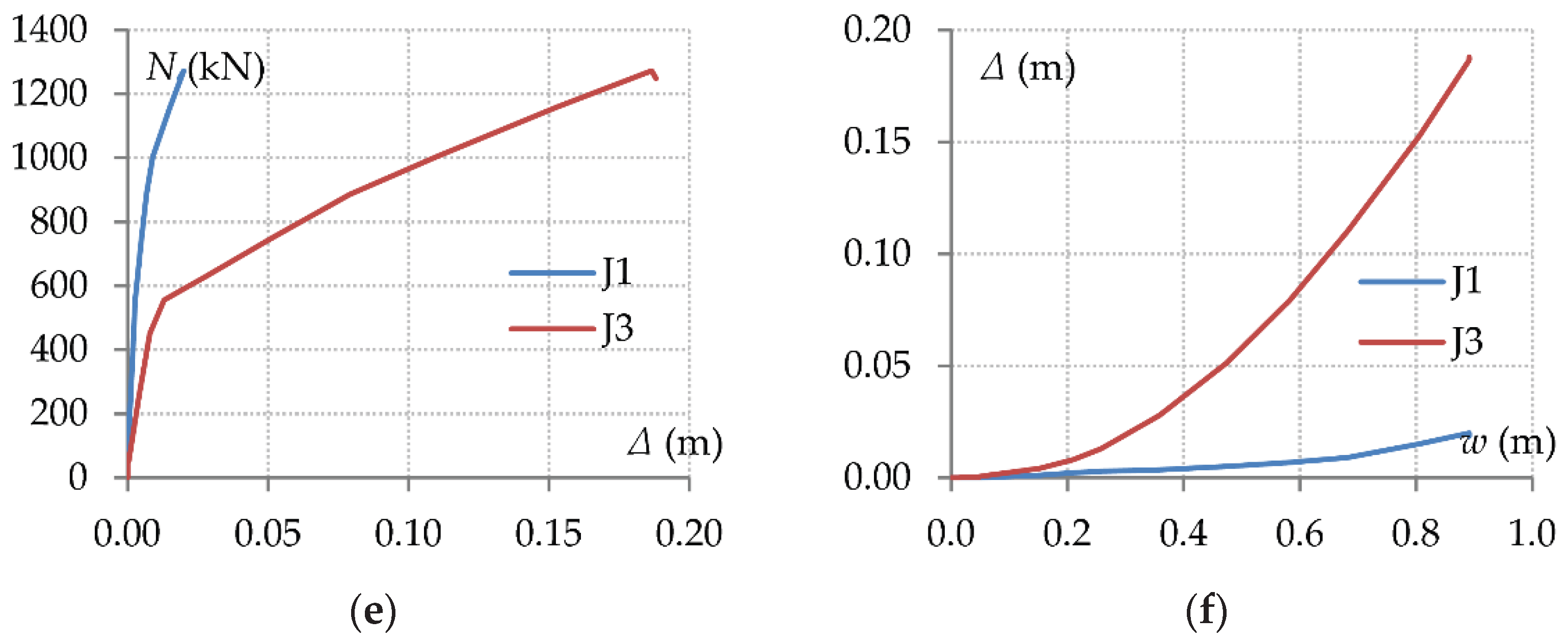
Figure 9.
Formation of plastic hinges at various stages of response following column removal.
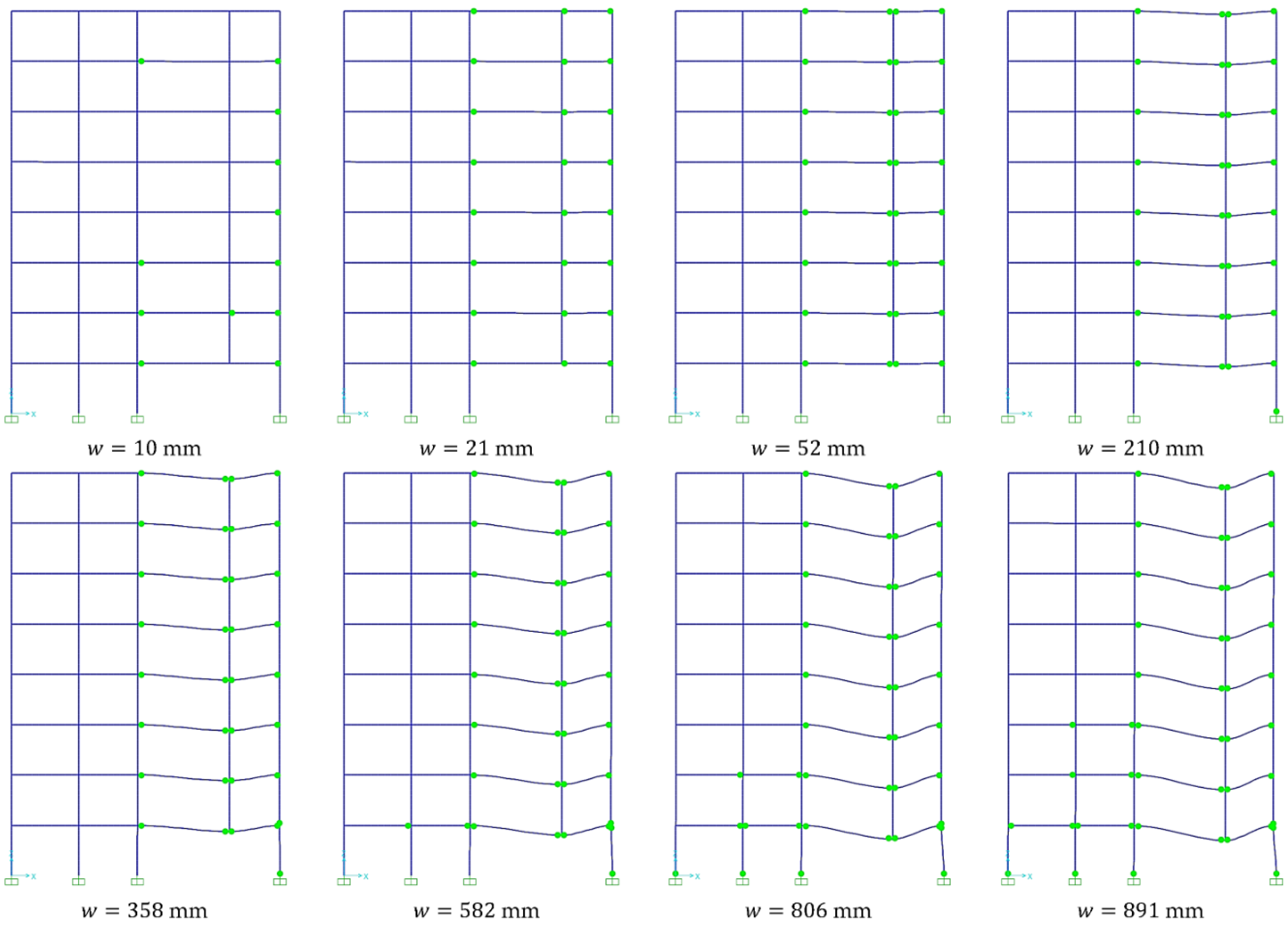
Figure 10.
Structural response of upper floors: (a) Relative displacement of the left-side and right-side joints; (b) Axial force-bending moment interaction diagrams of the left-side end connections.
Figure 10.
Structural response of upper floors: (a) Relative displacement of the left-side and right-side joints; (b) Axial force-bending moment interaction diagrams of the left-side end connections.
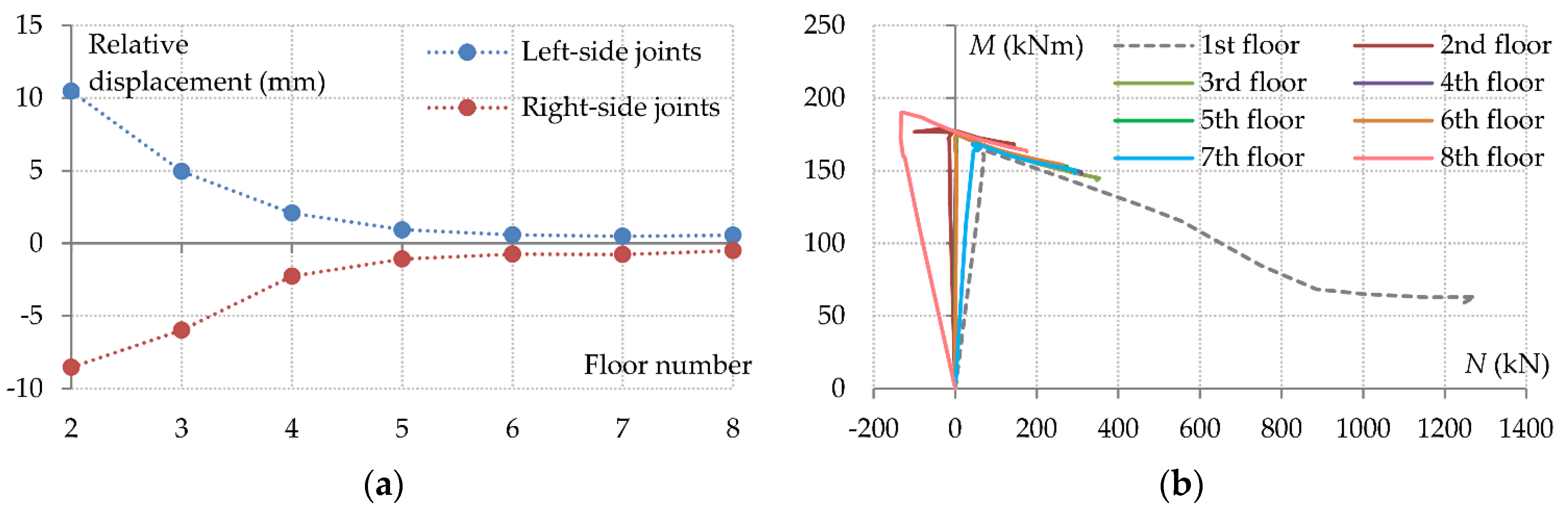
Figure 11.
Reduced 3-dimensional models and corresponding collapse mechanisms: (a) Multiple floor system; (b) Single floor system; (c) Grillage system.
Figure 11.
Reduced 3-dimensional models and corresponding collapse mechanisms: (a) Multiple floor system; (b) Single floor system; (c) Grillage system.
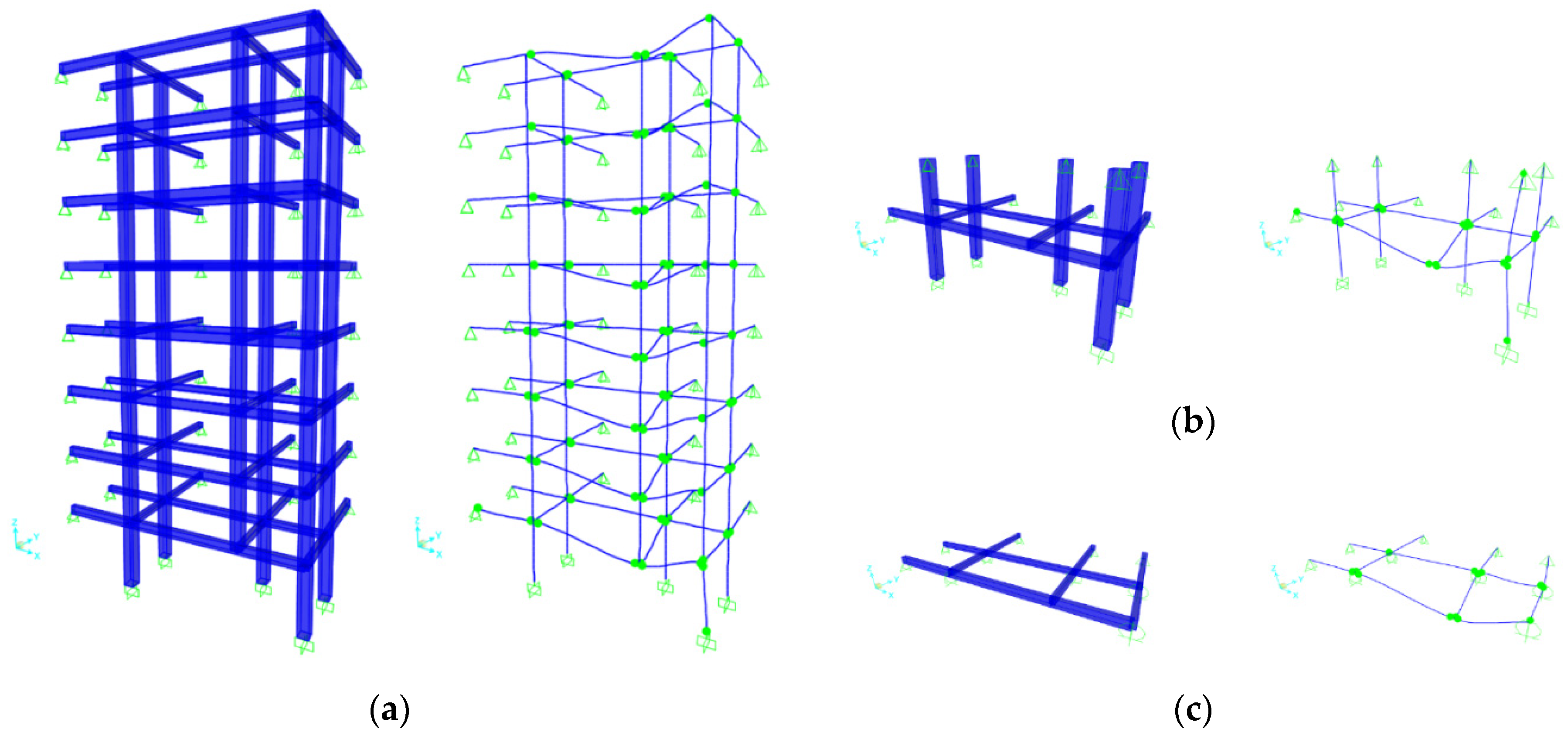
Figure 12.
Comparison between results from different models: (a) Beam load-deflection curves; (b) Bending moment of connection C1-1 vs. beam deflection; (c) Beam axial force vs. beam deflection; (d) Beam axial force vs. axial displacement of joint J3.
Figure 12.
Comparison between results from different models: (a) Beam load-deflection curves; (b) Bending moment of connection C1-1 vs. beam deflection; (c) Beam axial force vs. beam deflection; (d) Beam axial force vs. axial displacement of joint J3.
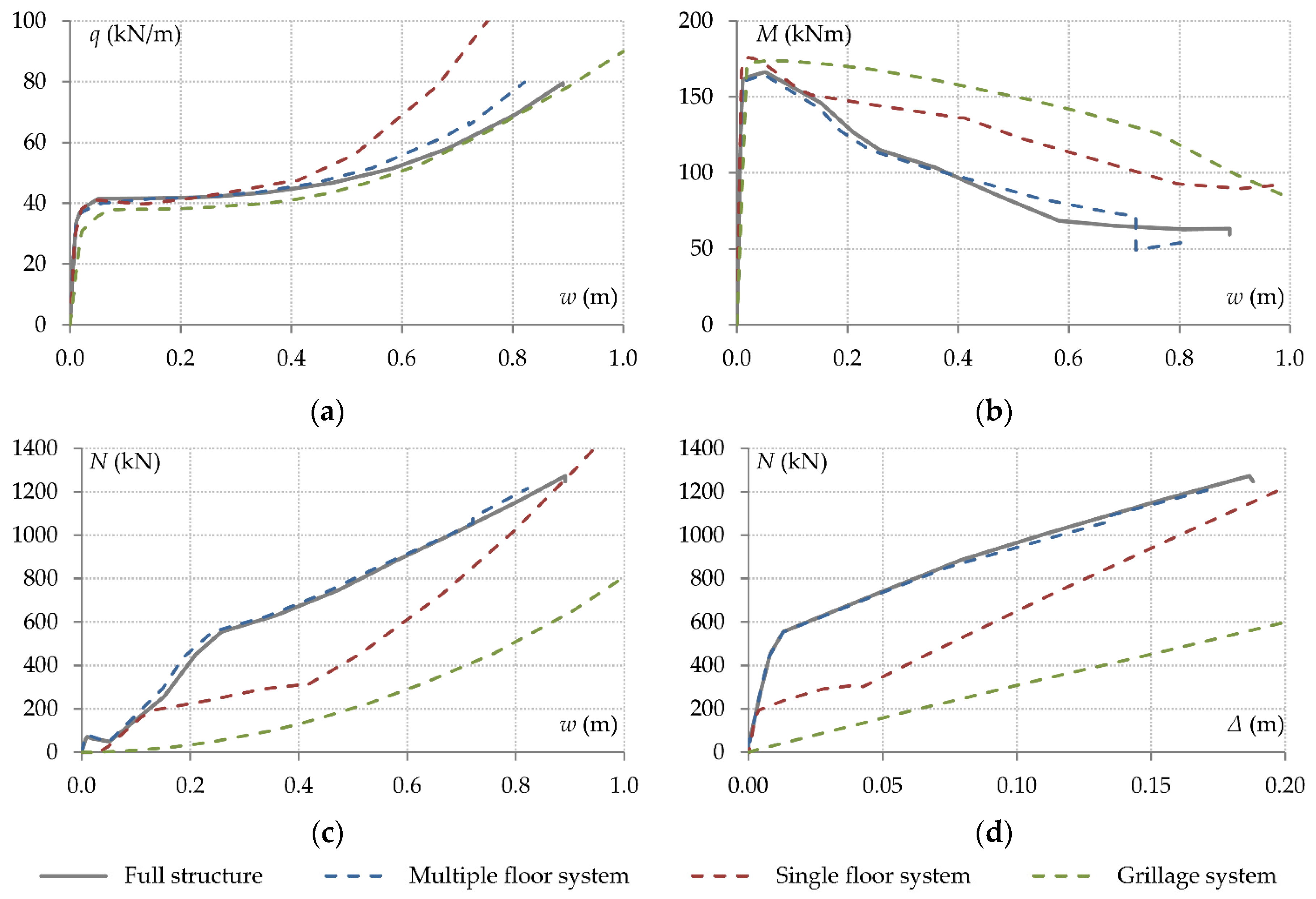
Figure 13.
Reduced 2-dimensional model: (a) Model layout; (b) Collapse mechanism and deformation mode.
Figure 13.
Reduced 2-dimensional model: (a) Model layout; (b) Collapse mechanism and deformation mode.
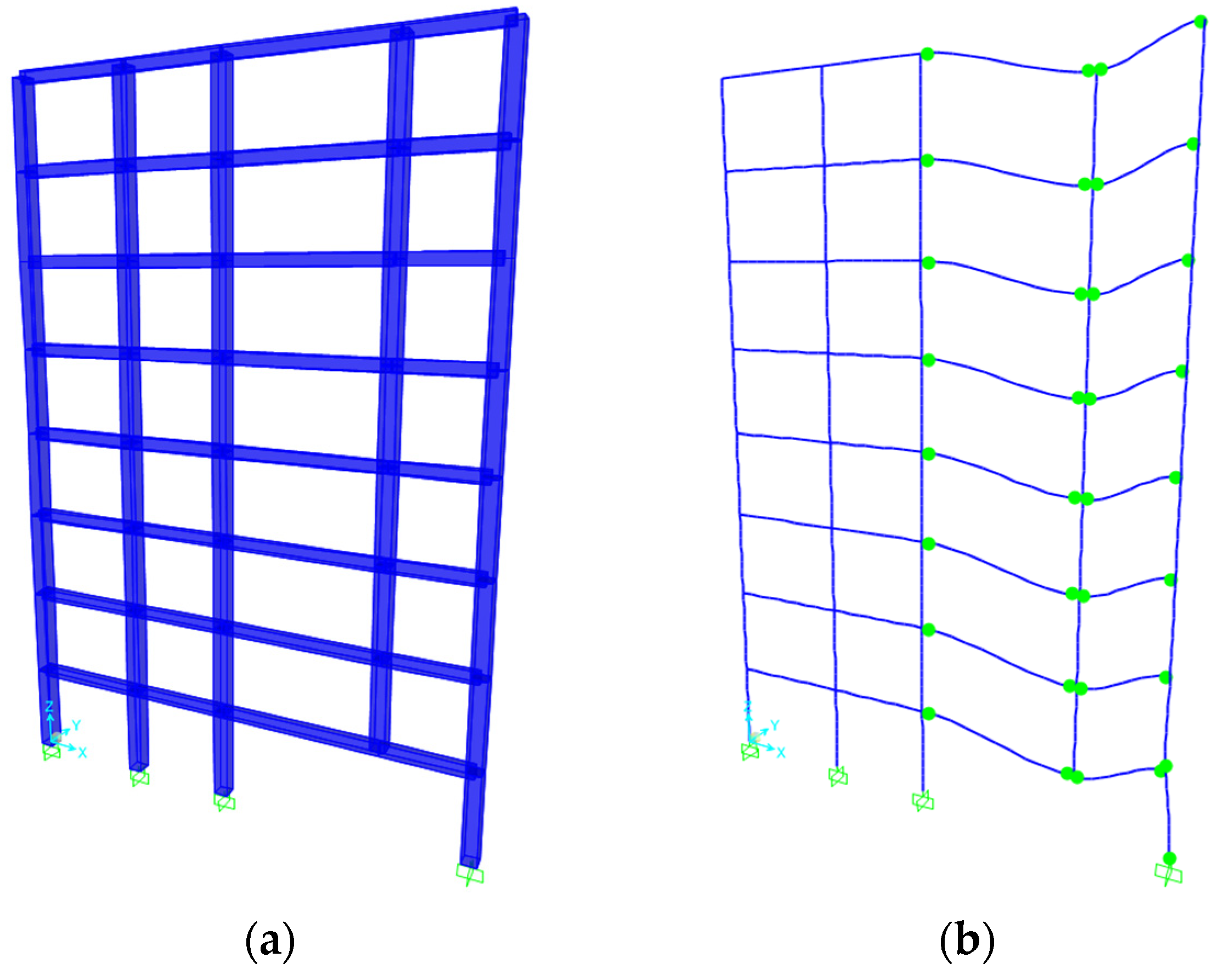
Figure 14.
Comparison between full structure and plane frame models: (a) Beam load-deflection curves; (b) Bending moment of connection C1-1 vs. beam deflection; (c) Beam axial force vs. beam deflection; (d) Beam axial force vs. axial displacement of joint J3.
Figure 14.
Comparison between full structure and plane frame models: (a) Beam load-deflection curves; (b) Bending moment of connection C1-1 vs. beam deflection; (c) Beam axial force vs. beam deflection; (d) Beam axial force vs. axial displacement of joint J3.
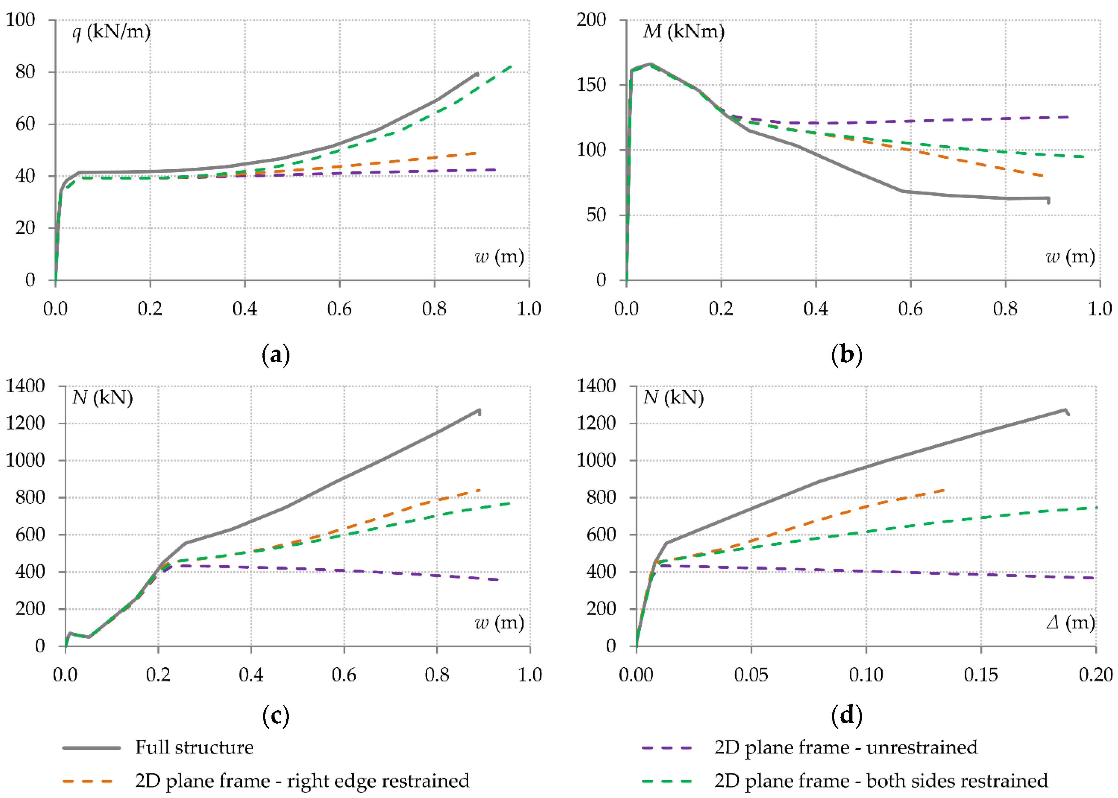
Figure 15.
Double-span beam model: (a) Model layout; (b) Collapse mechanism and deformation mode.
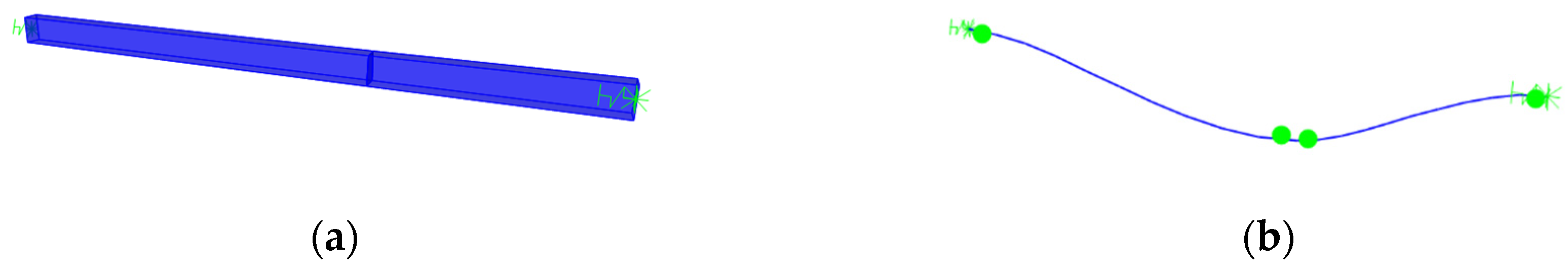
Figure 16.
Comparison between full structure model and double-span beam model with linear springs simulating axial support conditions: (a) Beam load-deflection curves; (b) Bending moment of connection C1-1 vs. beam deflection; (c) Beam axial force vs. beam deflection; (d) Beam axial force vs. axial displacement of joint J1 (dashed curves) and joint J3 (solid curves).
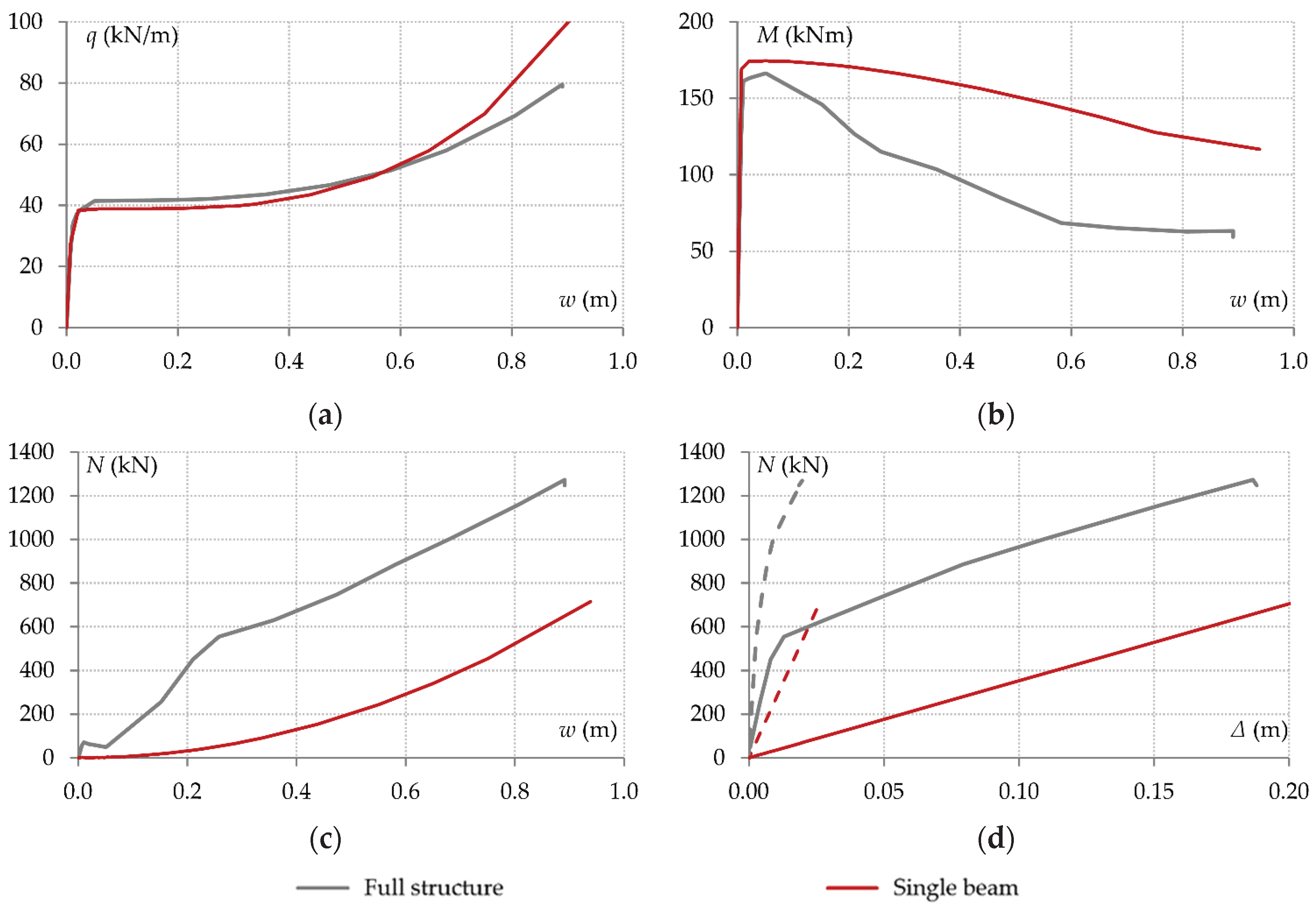
Figure 17.
Comparison between full structure model and double-span beam model with bi-linear springs simulating axial support conditions: (a) Beam load-deflection curves; (b) Bending moment of connection C1-1 vs. beam deflection; (c) Beam axial force vs. beam deflection; (d) Beam axial force vs. axial displacement of joint J1 (dashed curves) and joint J3 (solid curves).
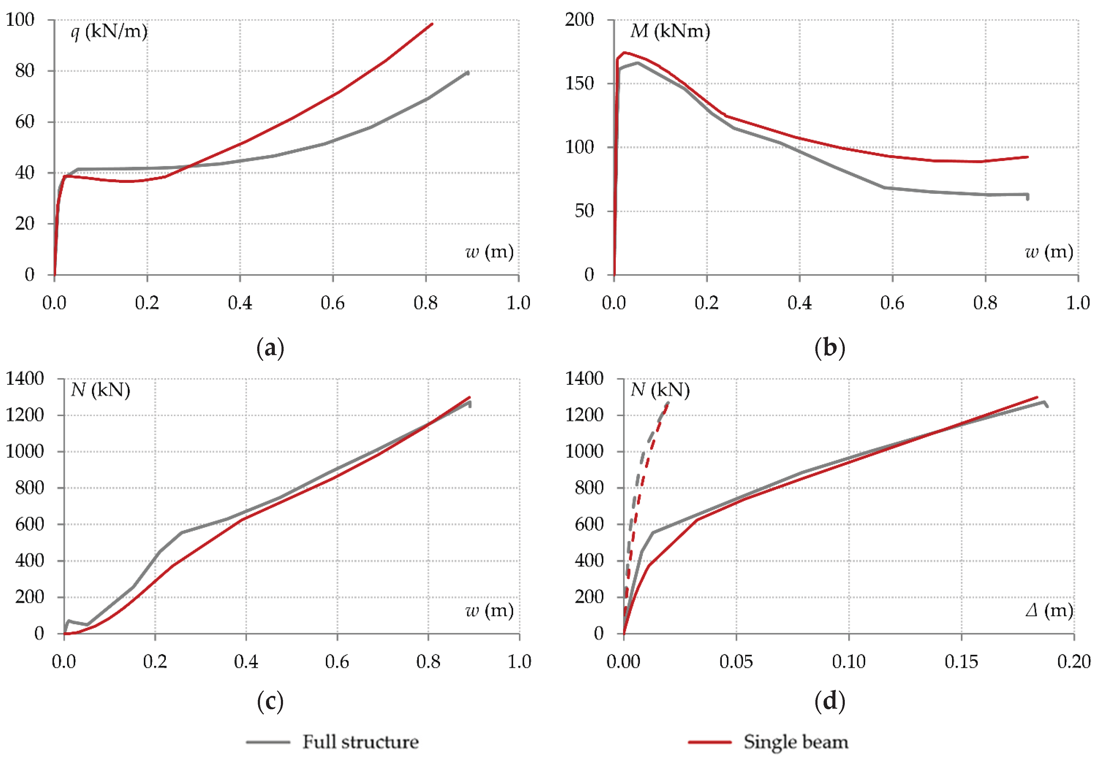
Figure 18.
Rotations of end joints of double-span beam system: (a) Joint rotation vs. beam deflection; (b) Connection bending moment vs. joint rotation (i.e. M1-1 vs. rotation of J1 and M2-2 vs. rotation of J3).
Figure 18.
Rotations of end joints of double-span beam system: (a) Joint rotation vs. beam deflection; (b) Connection bending moment vs. joint rotation (i.e. M1-1 vs. rotation of J1 and M2-2 vs. rotation of J3).
Disclaimer/Publisher’s Note: The statements, opinions and data contained in all publications are solely those of the individual author(s) and contributor(s) and not of MDPI and/or the editor(s). MDPI and/or the editor(s) disclaim responsibility for any injury to people or property resulting from any ideas, methods, instructions or products referred to in the content. |
© 2025 by the authors. Licensee MDPI, Basel, Switzerland. This article is an open access article distributed under the terms and conditions of the Creative Commons Attribution (CC BY) license (http://creativecommons.org/licenses/by/4.0/).
Copyright: This open access article is published under a Creative Commons CC BY 4.0 license, which permit the free download, distribution, and reuse, provided that the author and preprint are cited in any reuse.


