
Submitted:
28 September 2025
Posted:
29 September 2025
You are already at the latest version
Abstract
The power sector faces two main challenges of high greenhouse gas emissions responsible for global warming and high dependence on fossil fuels. Although geothermal energy is significant and can play a leading role in emission reduction through increased generation, most of the resources are low to medium temperature resources with most of the power being generated by flash power plants. The organic Rankine cycle (ORC) is a promising for waste heat and low to medium temperature heat recovery. This study analysis the feasibility of an Organic Rankine cycle (ORC) for extra power generation from used brim exiting flashing stations of an operating flash technology geothermal power plant. Depending on the thermodynamic conditions, it is possible to install an organic Rankine plant as a bottoming plant to a conventional geothermal power plant, most of which are the flash power plants. In this study, a review of the organic Rankine cycle is done as well as a preliminary design of an organic Rankine plant proposed to recover heat from waste brine for generation of extra electricity. The study targeted Olkaria 1 Power Plant in Kenya, which applied a single stage flash technology for power generation. to utilize waste heat in used geothermal fluid exiting the flash stations for Olkaria IV flash power plant in Kenya. It was demonstrated that used brine exists the flash station at 12 bar exits with heat content of about 2,268,960 MWth/hr (mega-watt thermal/hour) which can be used to generate to 7.39 MWe by development of an Organic Rankine cycle to use the waste energy in brine. The study proposes development of an ORC geothermal power plant to generate electricity from brine leaving flash tanks to reduce energy wastage in brine with on n-pentane as the working fluid. The preliminary design and analysis shows that the investment is technically and economically feasible.
Keywords:
- Geothermal energy is high but its contribution to electricity generation hence the need to maximize energy extraction from available resources.
- Over 70% of global electricity generation is from single flash generation plants, which implies loss of useful energy in used brine.
- The selection of the most appropriate working fluid influences the cost and performance of the organic Rankine cycle.
- Developing an organic Rankine cycle plant to use waste brine from flash plants will have economic and environmental benefits through generation of extra electricity from waste brine.
- The organic Rankine cycle is an effective thermodynamic cycle for waste heat and low to medium heat recovery.
- The overall cycle efficiency and power generation can be increased by waste heat recovery using binary cycles
1. Introduction
1.1. Problem Statement
1.2. Rationale of the Study
2. Methodology N
2.1. Novelty and Contribution
Geothermal Energy Conversion Cycles
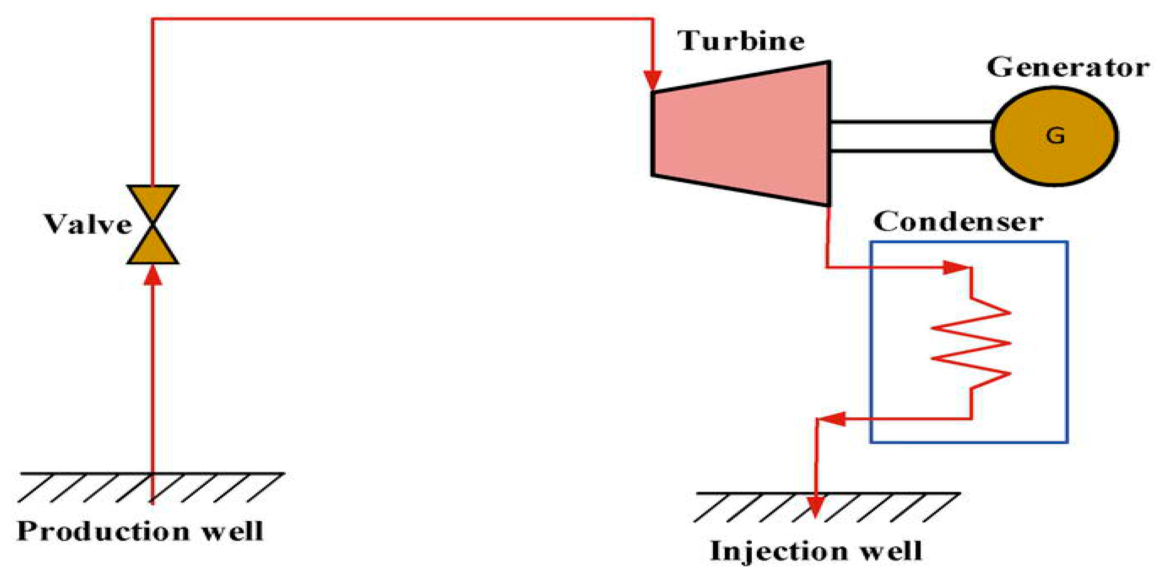
2.2. Dry Steam Plants
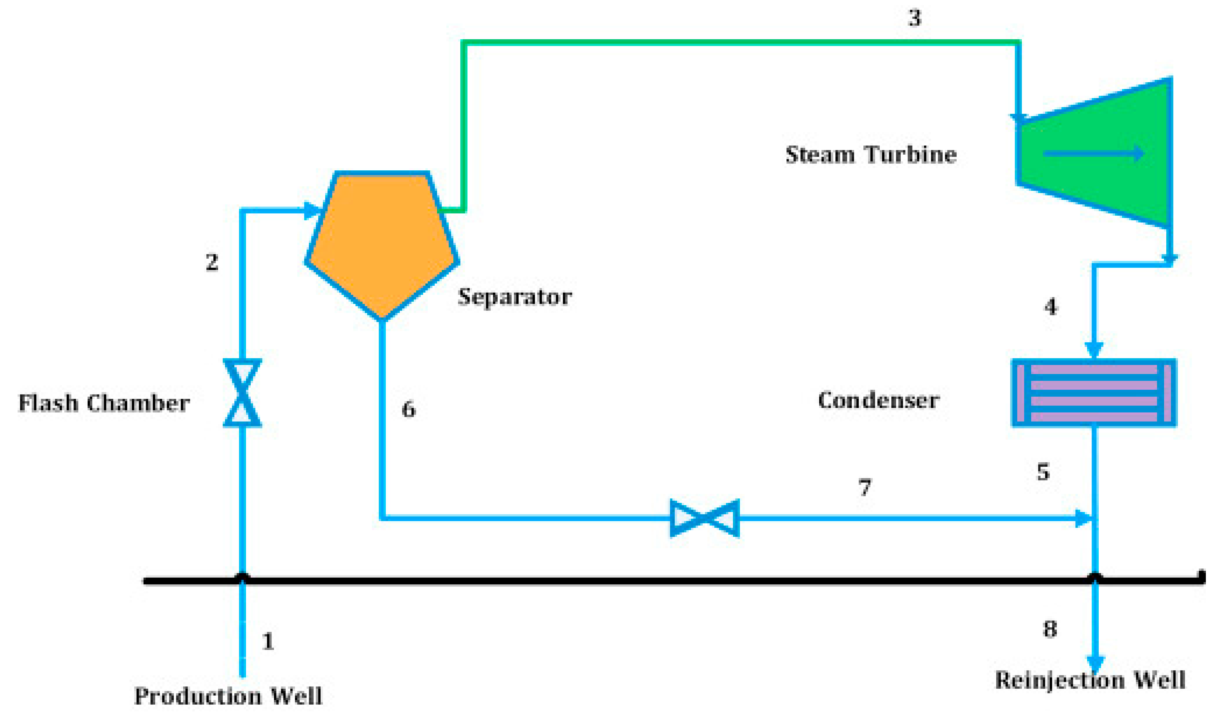
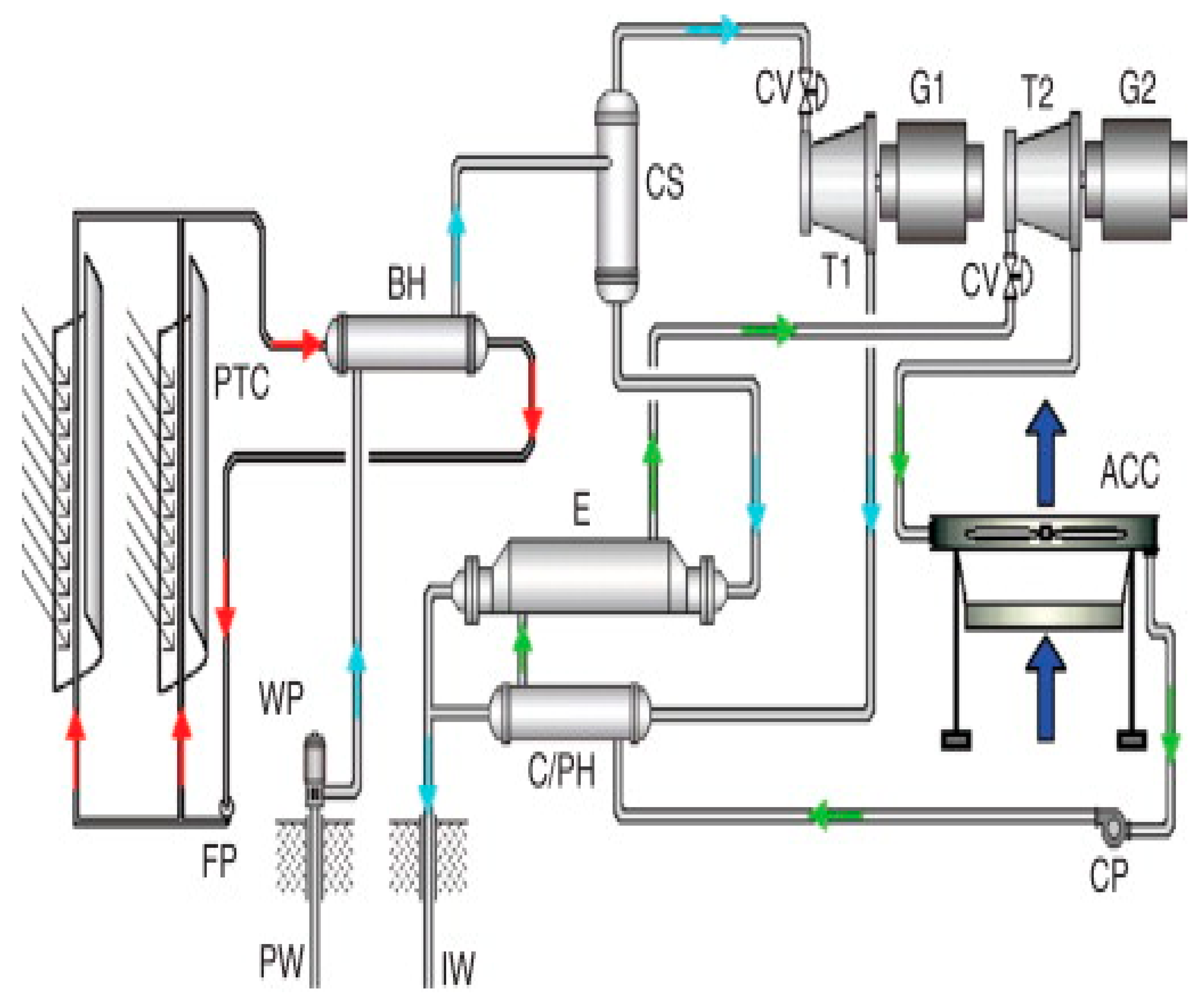
2.3. The Flash System
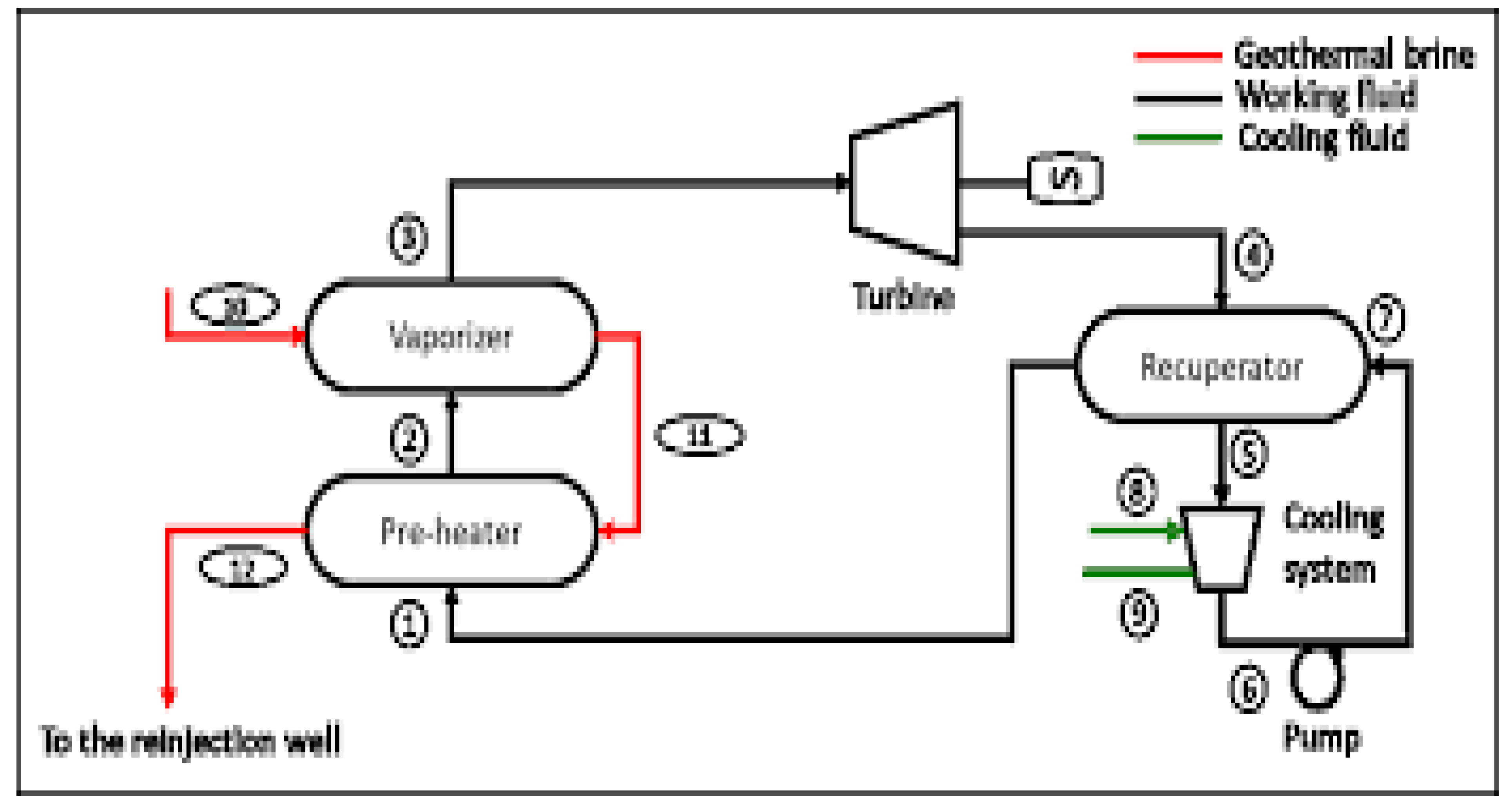
2.4. Binary Power Plants
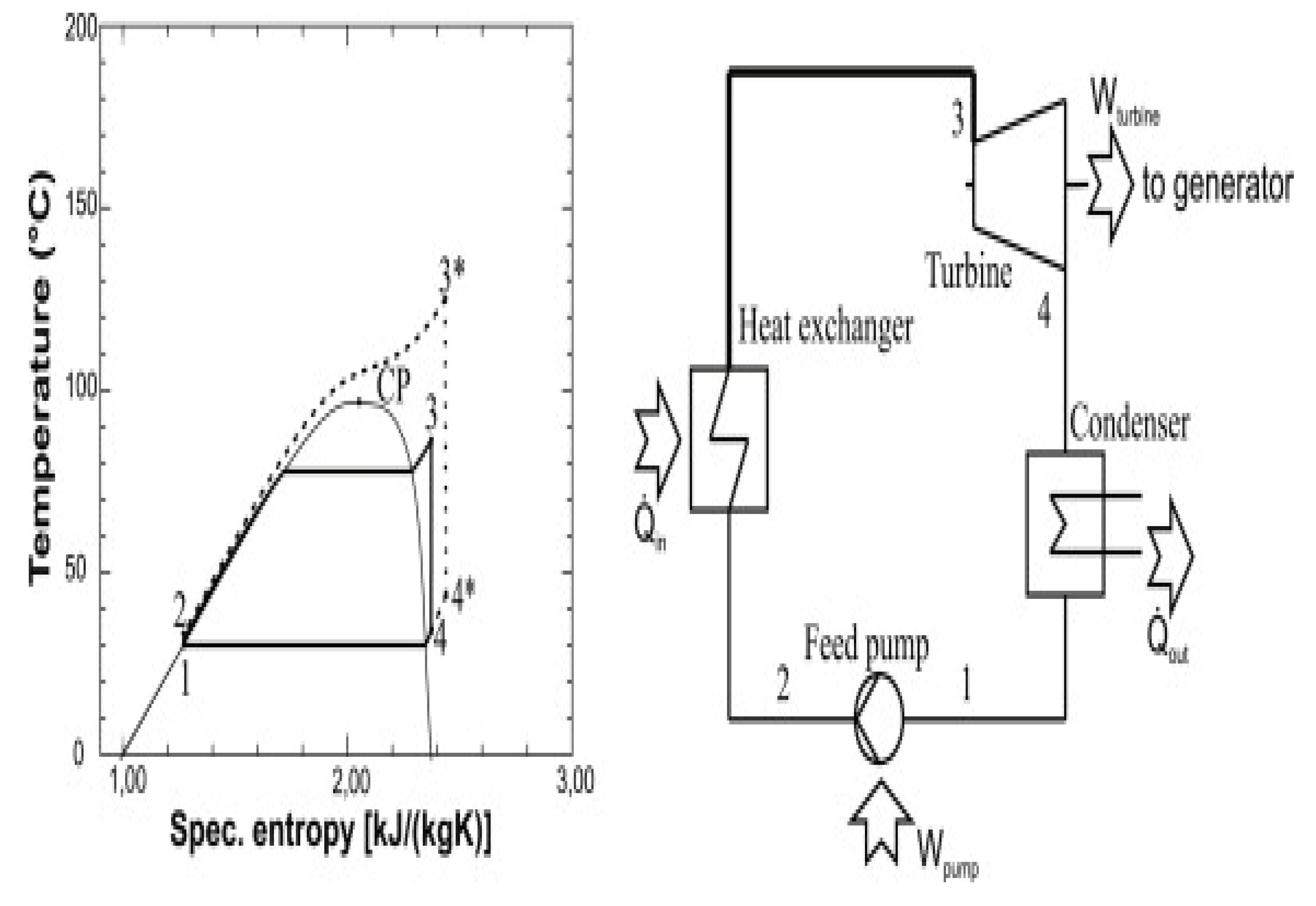
2.4.1. Organic Rankine and Kalina Cycles
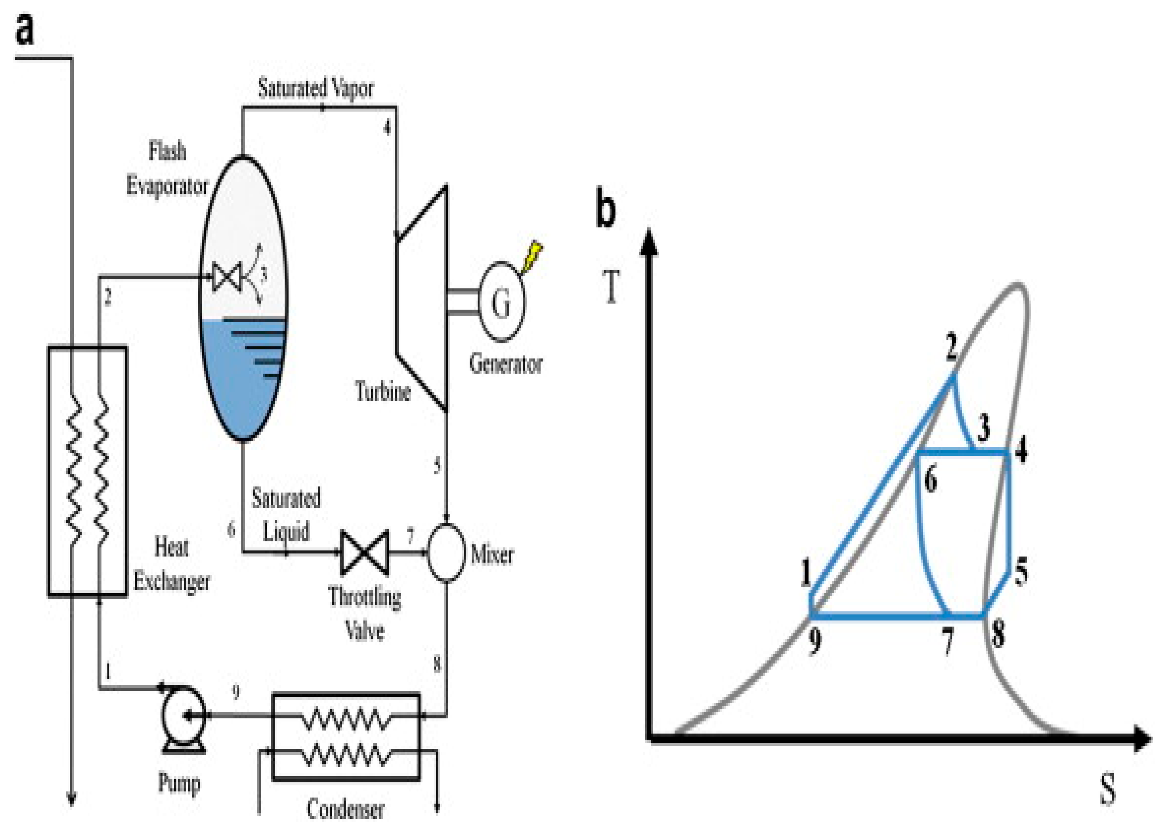
2.4.2. Organic Flash Cycle (OFC)/Regenerative Cycles
2.4.3. Supercritical Organic Rankine Cycles
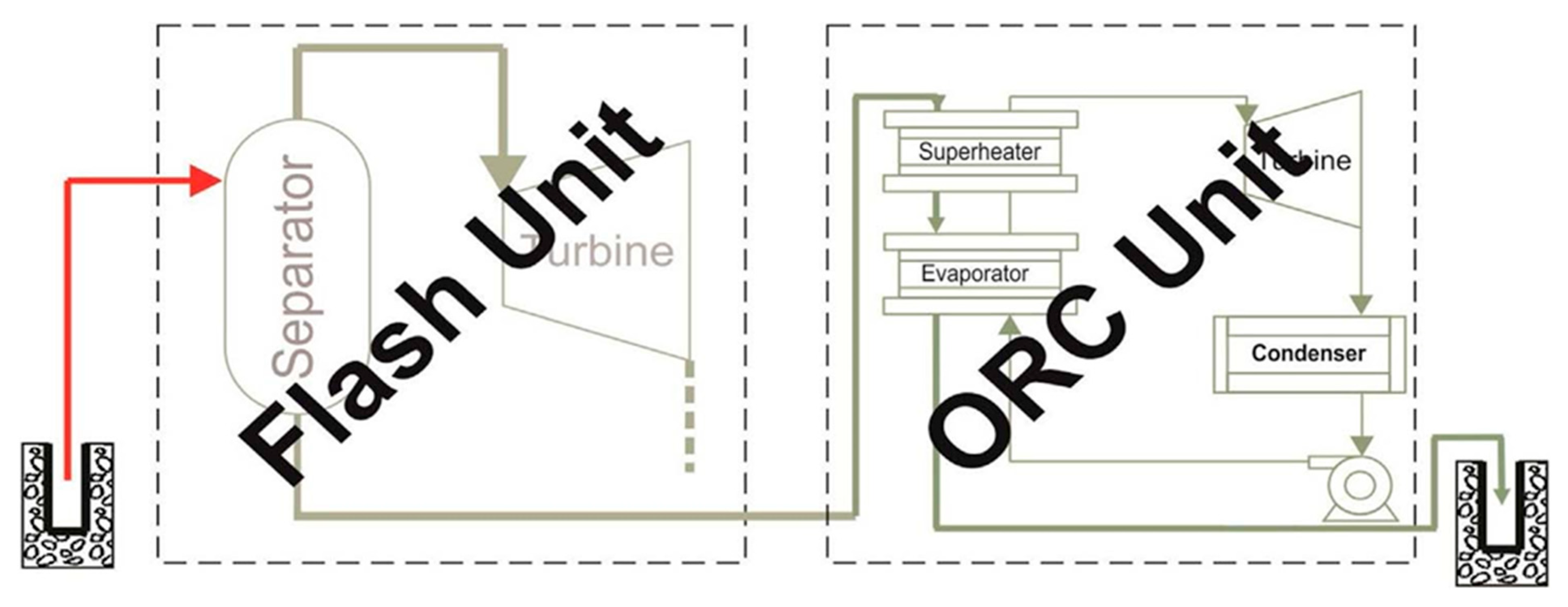
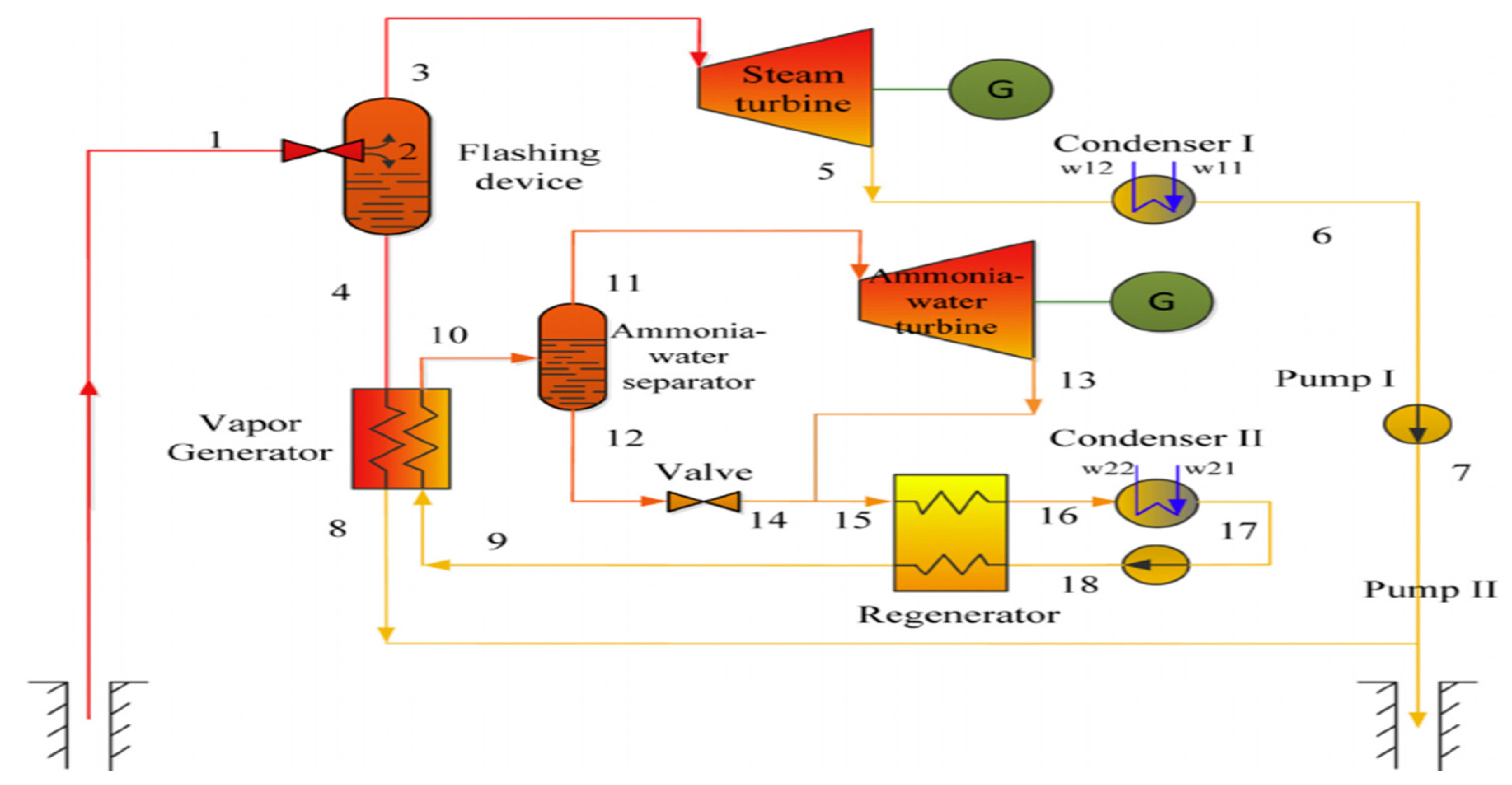
2.5. Combination Cycles
Flash/Binary Combined Cycle
2.6. Hybrid/Combined Cycles
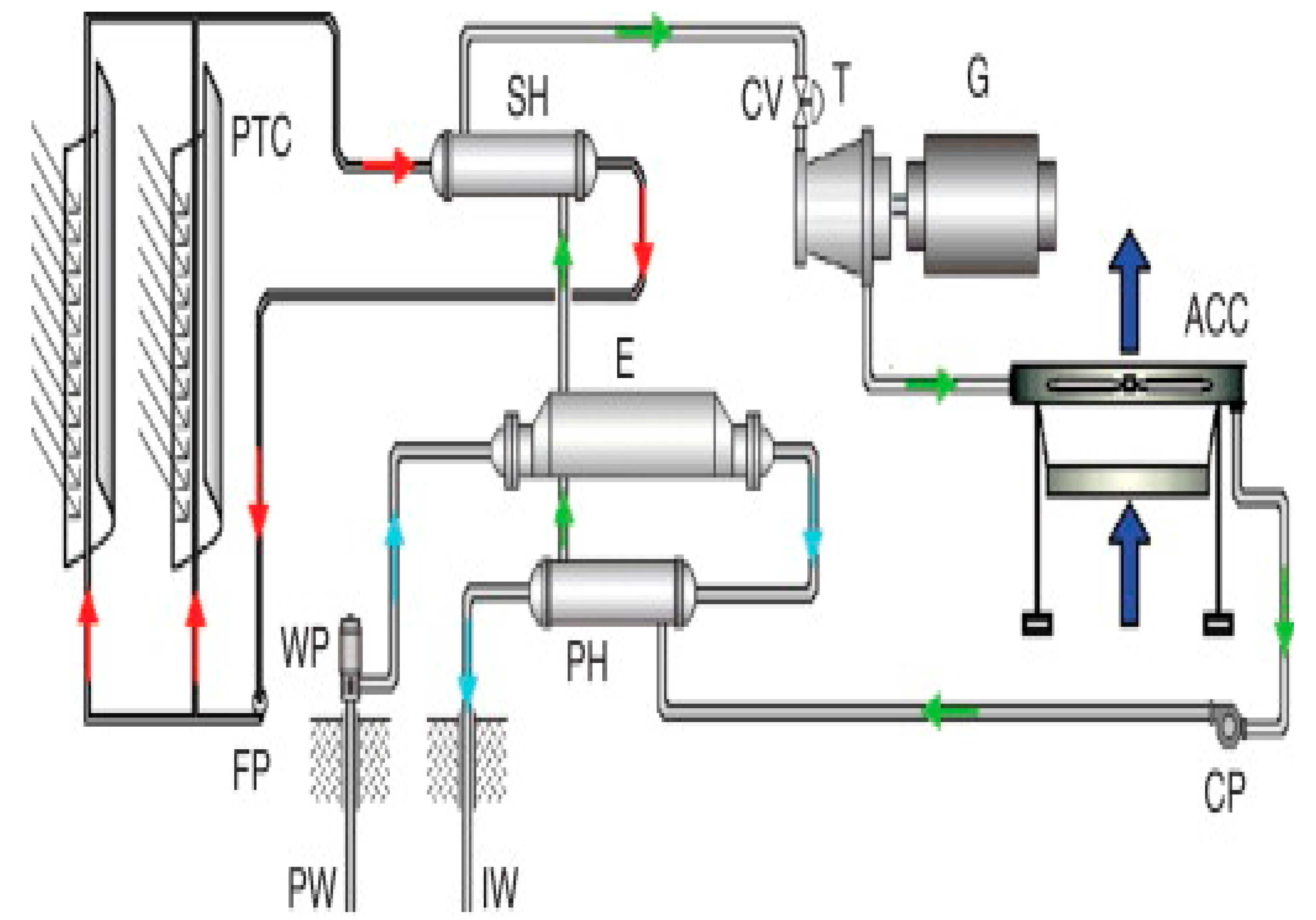
2.6.1. Solar-Thermal Combination Plant
2.6.2. Fossil-Geothermal Power Plants
2.7. Combined Heat and Power/Cogeneration Cycles
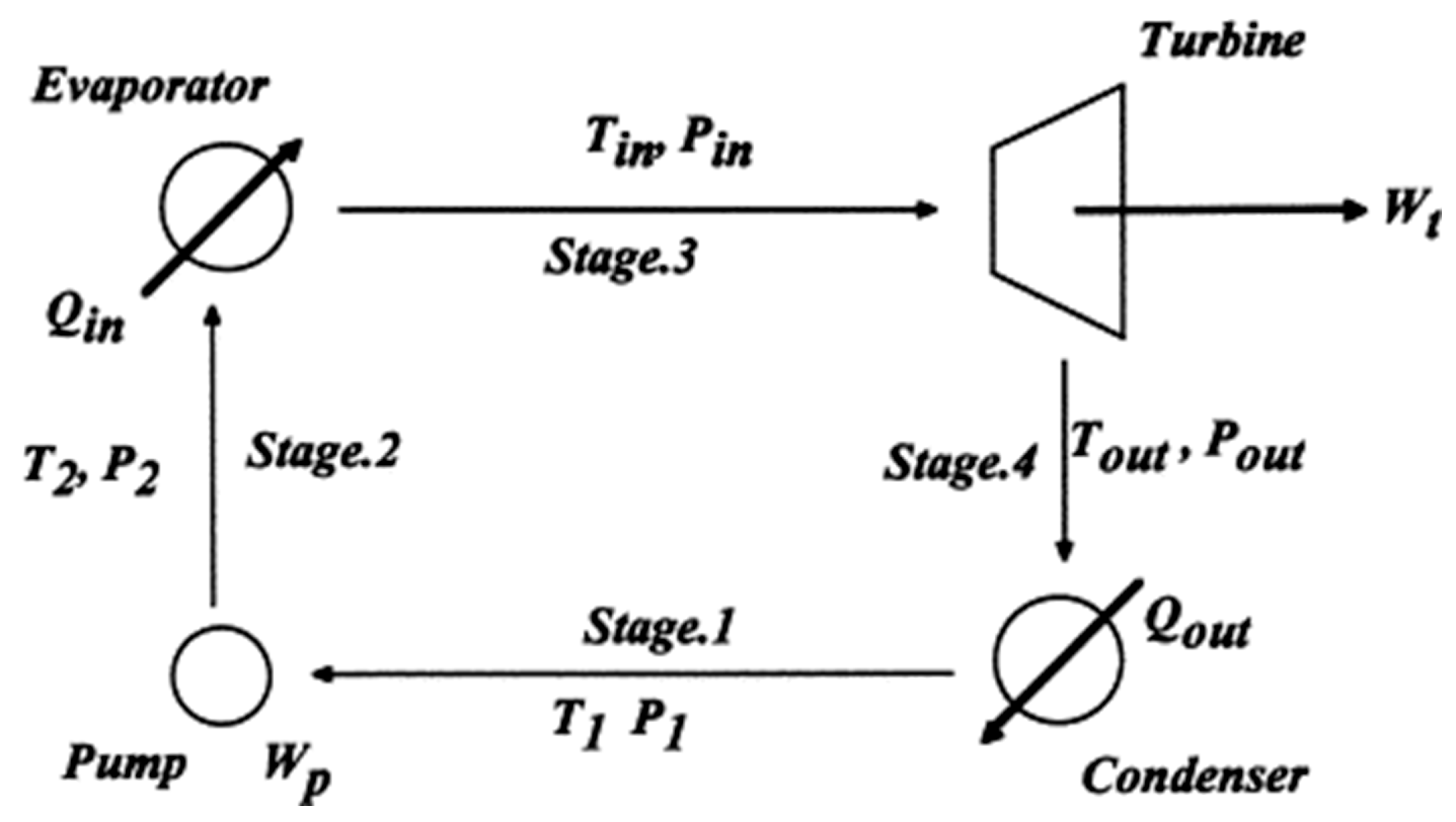
3. Design and Construction of Binary Cycle
3.1. Design Parameters
- i.)
- Identify the thermodynamic parameters for the cycle and hence identify the best working fluid.
- ii.)
- Determining the heat rates for the condenser and evaporator
- iii.)
- Model the expander and establish the expander [29].
- i.)
- It can use low temperature geothermal resources.
- ii.)
- It confines geothermal fluid to a closed loop and is pumped back to the ground through reinjection well without polluting the environment from the fluid and the no condensable gas.
- iii.)
3.2. Working Fluids for Organic Rankine Cycles
- i.)
- Exclude working fluids burnt in the Kyoto and Montreal protocol
- ii.)
- Exclude toxic or poisonous working fluids.
- iii.)
- Avoid fluids that can react with the equipment or environment.
- iv.)
- Avoid flammable working fluids.
- i.)
- The secondary medium may be flammable hence risky.
- ii.)
- The fluid may be hot water and medium temperature steam have higher requirements for piping and pumping compared to pure steam and is difficult to handle in mountainous areas.
- iii.)
- Higher operation costs and hence
- iv.)
- Some countries have stringent environmental regulations which do not allow the use of many of the organic fluids.
- v.)
- scaling, cavitation and corrosion of important parts like pumps and heat exchangers makes the system expensive due to shorter lifespan of equipment and increased cost of operation and maintenance [52].
3.3. Heat Exchangers
3.4. Optimum Design Operating Conditions
4. Material and Methods
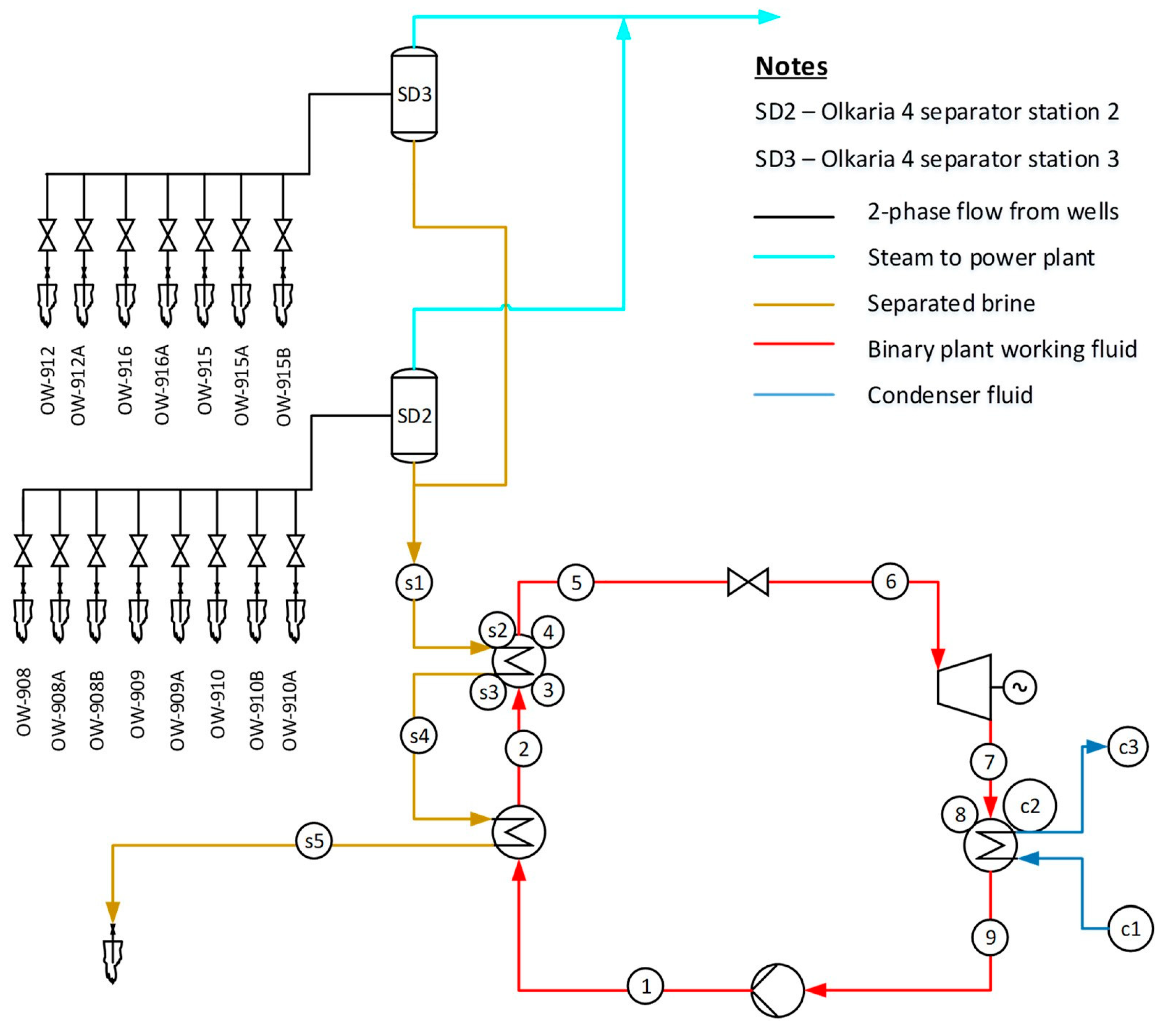
4.1. Performance Analysis of Olkaria IV
4.2. Proposed Design
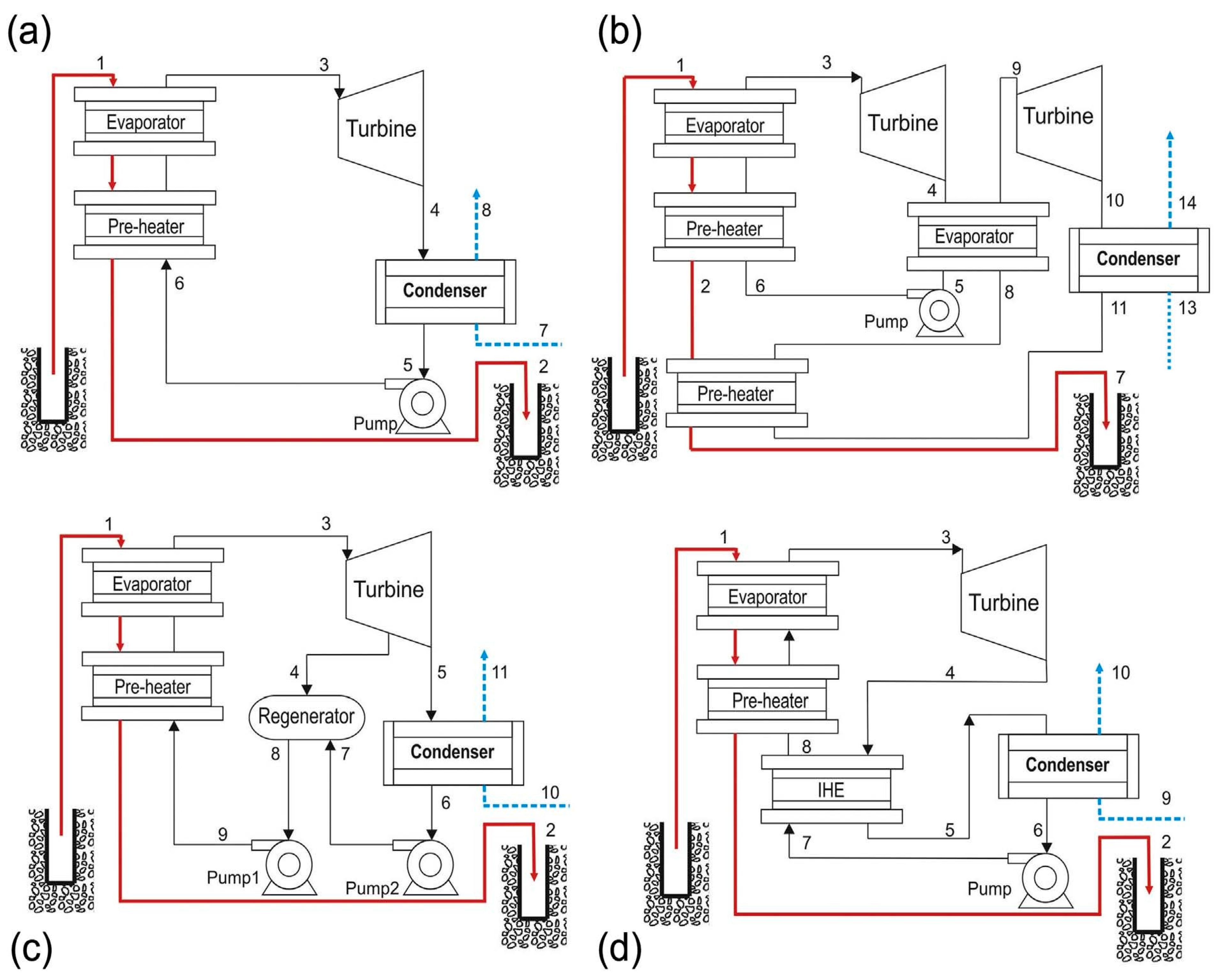
4.3. Cycle Selection
- i.)
- Basic ORC (B-ORC)
- ii.)
- Dual fluid ORC
- iii.)
- Regenerative ORC (R-ORC)
- iv.)
- ORC with Internal Heat Exchanger (IHE-ORC)
4.4. Thermodynamic Analysis and Assumption
- i.)
- The pressure and temperature losses in the equipment are neglected [83].
- ii.)
- The changes in the process assume steady state condition [30].
- iii.)
- iv.)
- The process assumes that compression and expansion take place the adiabatically and are also isentropic in pump and the turbine constant isentropic [30].
- v.)
- The ambient temperature is important for both a dead state and cooling water inlet temperature [30].
- vi.)
4.5. Working Fluid Selection
4.5.1. Pure Working Fluids
4.5.2. Working Fluid Mixtures
4.5.3. Cycle Optimization
4.6. The Heat Exchanger Design
- Area of heat transfer
- Overall heat transfers co-efficient.
- Temperature difference
4.6.1. Design and Construction
4.6.2. Type of Heat Exchangers
- Shell and tube heat exchangers
- Double pipe heat exchangers
- Plate heat exchangers
- Condensers, evaporators, and boilers
4.7. Shell and Tube
- i.)
- The tube and shell heat exchangers give very large surface area due to their design.
- ii.)
- Are simple to fabricate,
- iii.)
- Are easy to clean.
- iv.)
- Are adapted for high pressure vessels.
- v.)
- Can be made from several engineering materials.
- i.)
- mb(ha−hc) = m.wf(h1−h4)
- ii.)
- mbcb(Ta−Tc)=m.wf(h1−h4)
- iii.)
- mb=m. wfh1−h4cb (Ta−Tc)
- i.)
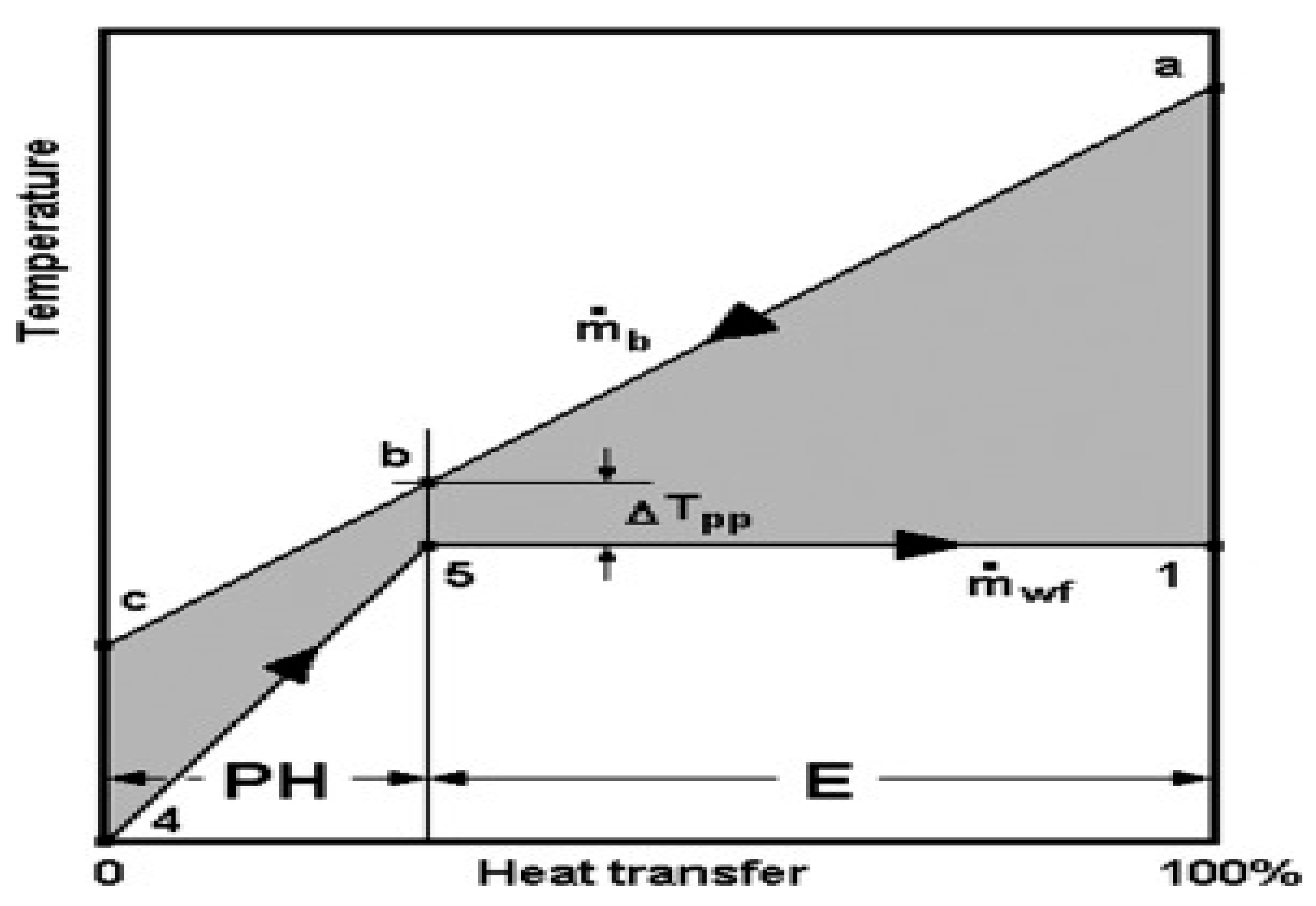
- Preheater: mbcb(Tb−Tc) =m·wf(h5−h4)
- ii.)
- Evaporator: mbcb(Ta−Tb) =m·wf(h1−h5)
- i.)
- Q·E=ŪAELMTD
- ii.)
- LMTD=(Ta−T1) −(Tb−T5) ln [Ta−T1/Tb−T5]
- iii.)
- Q·E=mbcb (Ta−Tb) =m·wf(h1−h5)
- iv.)
- QPH=ŪAPHLMTD
- v.)
- LMTDPH=(Tb−T5) −(Tc−T4) ln [Tb−T5Tc−T4]
- vi.)
- Q·PH=mbcb(Tb−Tc) =m·wf(h5−h4)
4.7.1. Heat Transfer Coefficients
4.7.2. Choice of Flow Configuration for the Heat Exchanger
4.7.3. Tube Sheets of the Heat Exchanger
4.7.4. Design of Heat Exchanger Baffles
4.7.5. Calculation of Heat Transfer Areas
4.8. Organic Rankine Cycle Design
4.8.1. Pre-Heaters
4.8.2. Evaporator
- i.)
- Heat used to raise the temperature of the working fluid to boiling point given by the expression, , where and stand for brine enthalpy at evaporator boiling point and exit point, is enthalpy at evaporator boiling point while is enthalpy of working fluid at evaporator.
- ii.)
- Latent heat of vaporization
- iii.)
- Heat for superheating the working fluid.
4.8.3. Condenser
4.8.4. Feed Pumps
4.8.5. ORC Turbine
4.8.6. Cycle Efficiency
5. Plant Design and Analysis
5.1. Comparison with Alternative Working Fluid
5.2. Assumptions
5.3. Design and Operations Characteristics
5.4. Power Produced
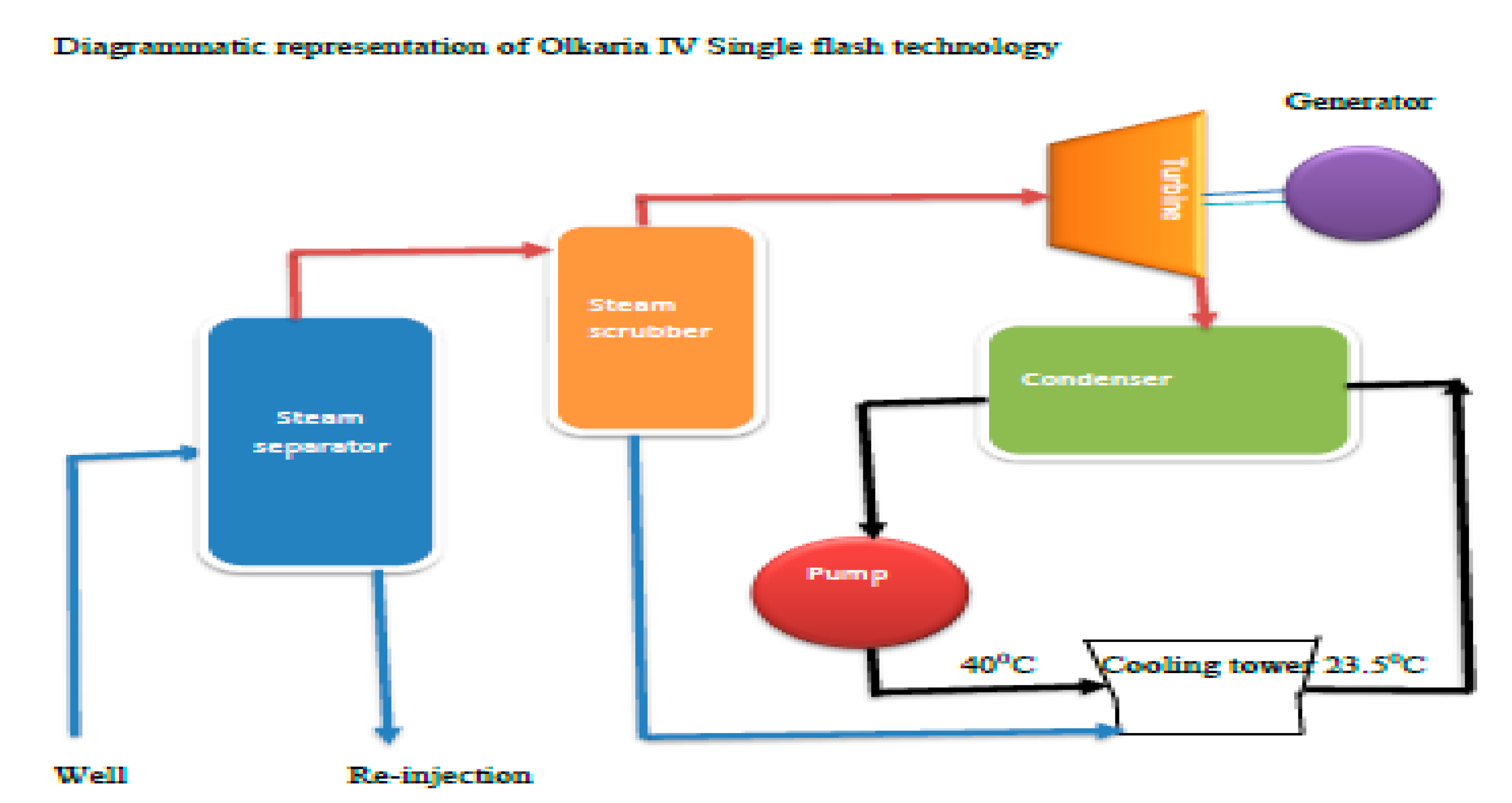
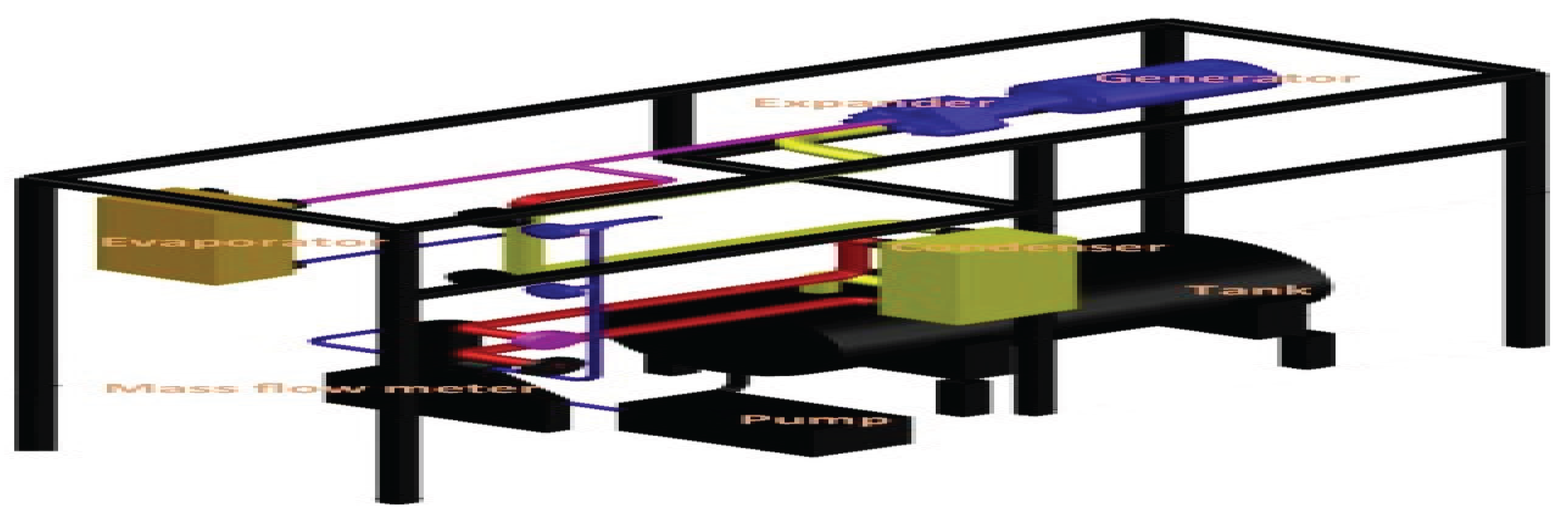
5.5. Technology in Use and Plant Description
5.6. Comparing the Optimum Operating Conditions
5.7. Comparing the Cost of Equipment
5.8. Economic Evaluation of the ORC Plant
5.9. Fouling/Scaling Effect
- i.)
- The heat exchanger is designed such that the working fluid i.e., pentane will flow through the shell side while the hot brine is contained in the copper tubes of the evaporator. This makes maintenance easier since the fouling fluid is on the easier to clean shell side.
- ii.)
- The temperature of the brine should not be cooled below 1300C. Below this temperature, precipitation will occur leading to formation of an insoluble calcium carbonate salt that will yield up to form scales that may cause pipe blockage or even pipe burst.
- iii.)
- To design against scaling in the heat exchanger, the flow direction and variables are considered to increase the velocity of the brine in the heat exchanger. The heat exchanger is tilted at an angle to allow brine flow to flow at higher velocity in the copper tubes.
- iv.)
- Furthermore, any formed scales can be wiped out and carried away by gravity as the brine flows in the copper tubes of the heat exchanger.
- v.)
- Use of chemical additives such as scale inhibitors and anti-scalants to reduce the carbonate concentration in the brine to reduce the Calcium carbonate formation.
5.10. Cavitation in the ORC Turbines/Expanders and Pumps
- i.)
- The match between pump and expander:
- ii.)
- The match between evaporator and condenser
- iii.)
- The match between heat source and ORC
- i.)
- proper material selection (either alloy steels or stainless steels), adequate polishing of turbine surfaces (proper machining)
- ii.)
- Selecting turbines with low specific speeds. This being a design Consideration, impulse turbine is selected because it operates at lower specific speeds.
5.11. Cooling for Organic Rankine Cycle
5.12. Non Condensable Gases
6. Results and Discussion
6.1. Summary of Results
6.2. Design Strength and Weaknesses
6.3. Recommendations
7. Conclusion
Author Contributions
Funding
Availability of Data
Acknowledgments
Conflicts of Interest
Ethical Approval and Consent to Participate
Consent for Publication
Abbreviations
References
- Ó. García-Afonso, A. M. Delgado-Torres, and B. González-Díaz, "Potential of Organic Rankine Cycle for waste heat recovery from piston engine-based power plants in isolated power systems," Applied Thermal Engineering, vol. 203, p. 117815, 2022/02/25/ 2022. [CrossRef]
- G. Polanco Piñerez, G. Valencia Ochoa, and J. Duarte-Forero, "Energy, exergy, and environmental assessment of a small-scale solar organic Rankine cycle using different organic fluids," Heliyon, vol. 7, no. 9, p. e07947, 2021/09/01/ 2021. [CrossRef]
- M. Usman, M. Imran, F. Haglind, A. Pesyridis, and B.-S. Park, "Experimental analysis of a micro-scale organic Rankine cycle system retrofitted to operate in grid-connected mode," Applied Thermal Engineering, vol. 180, p. 115889, 2020/11/05/ 2020. [CrossRef]
- S. Hu, Z. Yang, J. Li, and Y. Duan, "A Review of Multi-Objective Optimization in Organic Rankine Cycle (ORC) System Design," Energies, vol. 14, no. 20, 2021. [CrossRef]
- W. Li and Z. Yu, "Cavitation models with thermodynamic effect for organic fluid cavitating flows in organic Rankine cycle systems: A review," Thermal Science and Engineering Progress, vol. 26, p. 101079, 2021/12/01/ 2021. [CrossRef]
- L. Rybach and T. Kohl, "Waste heat problems and solutions in geothermal energy,", Special Publications, vol. 236, pp. 369-380. [CrossRef]
- M. J. B. Kabeyi and A. O. Oludolapo, "Central versus wellhead power plants in geothermal grid electricity generation," Energy, Sustainability and Society vol. 11, no. 7, pp. 1-23, 2021, Art no. ESSO-D-20-00011R4. [CrossRef]
- F. V. Hackstein and R. Madlener, "Sustainable operation of geothermal power plants: why economics matters," Geothermal Energy, vol. 9, no. 1, p. 10, 2021/03/15 2021. [CrossRef]
- M. J. B. Kabeyi and A. O. Oludolapo, "Central versus wellhead power plants in geothermal grid electricity generation," Energy, Sustainability and Society vol. 11, no. 7, p. 23, 2021. [CrossRef]
- R. DiPippo, Geothermal power plants. Principles, applications, case studies and environmental impact, 2 ed. Kidlington, United Kingdom: Elsevier, 2007, p. 493.
- M. J. B. Kabeyi and O. A. Olanrewaju, "Biogas Production and Applications in the Sustainable Energy Transition," Journal of Energy, vol. 2022, no. 8750221, p. 43, 2022/07/09 2022. [CrossRef]
- M. Kabeyi and O. Olanrewaju, "Slaughterhouse waste to energy in the energy transition with performance analysis and design of slaughterhouse biodigestor," (in en), Journal of Energy Management and Technology, vol. 6, no. 3, pp. 188-208, 2022. [CrossRef]
- M. J. B. Kabeyi, "Geothermal electricity generation, challenges, opportunities and recommendations," International Journal of Advances in Scientific Research and Engineering (ijasre), vol. 5, no. 8, pp. 53-95, 2019. [CrossRef]
- M. J. B. Kabeyi and A. O. Olanrewaju, "Feasibility of Wellhead Technology Power Plants for Electricity Generation," International Journal of Computer Engineering in Research Trends, vol. 7, no. 2, pp. 1-16, 2020. [CrossRef]
- S. Quoilin, M. V. D. Broek, S. Declaye, P. Dewallef, and V. Lemort, "Techno-economic survey of Organic Rankine Cycle (ORC) systems," Renewable and Sustainable Energy Reviews, vol. 22, pp. 168-186, 2013/06/01/ 2013. [CrossRef]
- I. Obernberger, H. Carlsen, and F. Biedermann, "State-of -the art and future developments regarding small scale biomass CHP systems with special focus on ORC and Stirling engine technologies," presented at the International Nordic Bioenergy 2003 conference, 2003. [Online]. Available: https://graz.pure.elsevier.com/en/publications/state-of-the-art-and-future-developments-regarding-small-scale-bi.
- A. Ahmadi et al., "Applications of geothermal organic Rankine Cycle for electricity production," Journal of Cleaner Production, vol. 274, p. 122950, 2020/11/20/ 2020. [CrossRef]
- M. J. B. Kabeyi and O. A. Olanrewaju, "Dual cycle cogeneration plant for an operating diesel powerplant," presented at the 11th Annual International Conference on Industrial Engineering and Operations Management, Singapore, March 7-11, 2021, 2021. [Online]. Available: http://www.ieomsociety.org/singapore2021/papers/200.pdf.
- M. J. B. Kabeyi and O. A. Olanrewaju, "Fuel from plastic wastes for sustainable energy transition," presented at the 11th Annual International Conference on Industrial Engineering and Operations Management, Singapore, March 7-11, 2021, 2021. [Online]. Available: http://www.ieomsociety.org/singapore2021/papers/199.pdf.
- US Department of Energy, "Modifications and Optimization of the Organic Rankine Cycle," June 2017 2017. [Online]. Available: https://www.energy.gov/sites/prod/files/2017/09/f36/0463-INL-062817-compliant.pdf.
- G. Di, L. Giovannelli, Ambra, B. Pietro, and F. Fantozzi, "Comparison of mini Organic Rankine Cycle plants for waste heat recovery," presented at the AIP Conference Proceedings 2191, 2019. [Online]. Available: https://aip.scitation.org/doi/abs/10.1063/1.5138799.
- C. Spadacini, L. G. Xodo, and M. Quaia, "14 - Geothermal energy exploitation with Organic Rankine Cycle technologies," in Organic Rankine Cycle (ORC) Power Systems, E. Macchi and M. Astolfi Eds.: Woodhead Publishing, 2017, pp. 473-525.
- D. Meng, Q. Liu, and Z. Ji, "Performance analyses of regenerative organic flash cycles for geothermal power generation," Energy Conversion and Management, vol. 224, p. 113396, 2020/11/15/ 2020. [CrossRef]
- P. Valdimarsson, " Geothermal power plant cycles and main components " in Geothermal Drilling, Resource Development and Power Plants, Santa Tecla, El Salvador, January 16-22, 2011 2011, p. 24. [Online]. Available: https://geothermalcommunities.eu/assets/elearning/7.32.UNU-GTP-SC-12-35.pdf. [Online]. Available: https://geothermalcommunities.eu/assets/elearning/7.32.UNU-GTP-SC-12-35.pdf.
- G. G. Gitobu, "Model organic Rankine Cycle for Brine at Olkaria geothermal fiels, Kenya," United Nations University, 15, 2016. [Online]. Available: https://orkustofnun.is/gogn/unu-gtp-report/UNU-GTP-2016-15.pdf.
- M. Kopuničová, "Feasibility study of binary geothermal power plants in Eastern Slovakia - Analysis of ORC and Kalina power plants," MSc., The School of Renewable Energy Science,, University of Iceland and University of Akureyri., Akureyri, Iceland, 2009. [Online]. Available: https://geothermalcommunities.eu/assets/elearning/7.23.Martina_Kopunicova.pdf.
- Wolverine, Heat transfer to air-cooled heat exchangers Wolverine Tube Inc.,, 2018, p. 280. [Online]. Available: https://pdfgoal.com/downloads/wolverine_engineering_data_book_iii.
- C. Alimonti, P. Conti, and E. Soldo, "Selecting the Optimal Use of the Geothermal Energy Produced with a Deep Borehole Heat Exchanger: Exergy Performance," Proceedings, vol. 58, no. 1, p. 20, 2020. [Online]. Available: https://www.mdpi.com/2504-3900/58/1/20.
- V. Pethurajan, S. Sivan, and G. C. Joy, "Issues, comparisons, turbine selections and applications – An overview in organic Rankine cycle," Energy Conversion and Management, vol. 166, pp. 474-488, 2018/06/15/ 2018. [CrossRef]
- A. F. Castelli, C. Elsido, R. Scaccabarozz, Nord, Lars O., and E. Martelli, "Optimization of Organic Rankine cycles for waste heat recovery from Aluminiun production plants," Frontiers in Energy Research, vol. 7, no. 44, p. 19, 2019. [CrossRef]
- F. A. Ahangar, "Feasibility study of developing a binary power plant in the low-temperature geothermal field in puga, jammu and kashmir, india," presented at the GEOTHERMAL TRAINING PROGRAMME, Reykjavik, Iceland, 2012. [Online]. Available: http://jkspdc.nic.in/publication_files/geothermal_puga.pdf.
- M. J. B. Kabeyi and A. O. Oludolapo, "Design and Modelling of a Waste Heat Recovery System for a 250KW Diesel Engine for Cereal Drying," presented at the 2nd African International Conference on Industrial Engineering and Operations Management, Harare, Zimbabwe, 5-7 December 2020, 2020, 078 [Online]. Available: http://ieomsociety.org/harare2020/papers/78.pdf.
- M. J. B. Kabeyi and O. A. Olanrewaju, "Central versus wellhead power plants in geothermal grid electricity generation," Energy, Sustainability and Society, vol. 11, no. 1, p. 7, 2021/03/20 2021, Art no. ESSO-D-20-00011R4. [CrossRef]
- M. J. B. Kabeyi and O. A. Olanrewaju, "Geothermal wellhead technology power plants in grid electricity generation: A review," Energy Strategy Reviews, vol. 39, no. January 2022, p. 100735, 2022/01/01/ 2022. [CrossRef]
- P. F. Windrem and G. L. Marr, "Environmental Problems and Geothermal Permitting," Natural Resources Lawyer,, vol. 14, no. 4, pp. 675-685, 1982. [Online]. Available: https://www.jstor.org/stable/40922700.
- Y. Cao and M. A. Ehyaei, "Energy, exergy, exergoenvironmental, and economic assessments of the multigeneration system powered by geothermal energy," Journal of Cleaner Production, vol. 313, p. 127823, 2021/09/01/ 2021. [CrossRef]
- I. Dincer and A. Abu-Rayash, "Chapter 3 - Energy systems," in Energy Sustainability, I. Dincer and A. Abu-Rayash Eds.: Academic Press, 2020, pp. 59-92.
- I. Dincer and A. Abu-Rayash, Energy Sustainability, 2020. [Online]. Available: https://www.sciencedirect.com/topics/engineering/geothermal-power-plant.
- M. J. B. Kabeyi and A. O. Oludolapo, "Viability of Wellhead Power Plants as substitutes of Permanent Power plants," presented at the 2nd African International Conference on Industrial Engineering and Operations Management, Harare, Zimbabwe, December 7-10, 2020, 2020, 77. [Online]. Available: http://www.ieomsociety.org/harare2020/papers/77.pdf.
- M. J. B. Kabeyi and A. O. Oludolapo, "Characteristics and applications of geothermal wellhead powerplants in electricity generation," in SAIIE31 Proceedings, South Africa, H. Teresa, Ed., 5th – 7th October 2020 2020, vol. 2020, no. 31, South Africa: South African Institution of Industrial Engineers, pp. 222-235. [Online]. Available: https://www.dropbox.com/s/o0sj1l08v8n9sgh/SAIIE31%20Conference%20Proceedings.pdf?dl=. [Online]. Available: https://www.dropbox.com/s/o0sj1l08v8n9sgh/SAIIE31%20Conference%20Proceedings.pdf?dl=.
- R. DiPippo, "Chapter 8 - Binary Cycle Power Plants," in Geothermal Power Plants, R. DiPippo Ed. Oxford: Elsevier Science, 2005, pp. 163-196.
- N. Brender, "Feasibility study for a medium-enthalpy geothermal power plant in Rosario de la Frontera, Salta, Argentina," Master of Science in Energy and Environment, Energy and Environment, Karlsruhe Institute of Technology, Buenos Aires, 2018. [Online]. Available: https://ri.itba.edu.ar/handle/123456789/1568.
- National Renewable Energy Laboratory. "Geothermal Electricity Production Basics." National Renewable Energy Laboratory. https://www.nrel.gov/research/re-geo-elec-production.html (accessed 2021).
- Geothermal Energy Association, "Geothermal energy ". [Online]. Available: http://geo-energy.org/basics.aspx.
- C. Karytsas and D. Mendrinos, "Global Geothermal Power Market " presented at the European Geothermal Congress, Pisa, Italy, june, 2013. [Online]. Available: https://www.researchgate.net/publication/258926033Global_Geothermal_Power_Market.
- R. DiPippo, Geothermal Power Plants: Principles, Applications, Case Studies and Environmental Impact, 3 ed. Oxford: Elsevier.Ltd, 2012, pp. 82-111.
- Khasani and F. S. Abdullah, "Thermodynamics analysis of single-flash wellhead geothermal power plant at Jailolo field, Halmahera," presented at the AIP Conference Proceedings 2001, 16 August 2018, 2018. [Online]. Available: https://aip.scitation.org/doi/abs/10.1063/1.5049984.
- H. M. D. P. Herath, M. A. Wijewardane, R. A. C. P. Ranasinghe, and J. G. A. S. Jayasekera, "Working fluid selection of Organic Rankine Cycles," Energy Reports, vol. 6, pp. 680-686, 2020/12/01/ 2020. [CrossRef]
- M. J. B. Kabeyi, "Investigating the challenges of bagasse cogeneration in the kenyan Sugar Industry," International Journal of Engineering Sciences & Research Technology, vol. 9, no. 5, pp. 7-64, May 2020 2020. [CrossRef]
- M. E. Assad, E. Bani-Hani, and M. Khalil, "Performance of geothermal power plants (single, dual, and binary) to compensate for LHC-CERN power consumption: comparative study," Geothermal Energy, vol. 5, no. 1, pp. 1-16, 2017. [CrossRef]
- M. H. Dickson and M. Fanelli, "Geothermal Energy," in Geothermal Energy: Utilization and Technology 1ed. Paris: UNESCO, 2003, p. 225.
- D. Bonalumi, P. A. Borbarda, and C. M. Inverrnizzi, "Zero emission geothermal flash power plant," presented at the 72nd Conference of the Italian Thermal Machines Engineering Association, Lecce, Italy, 6-8 September 2017, 2017, ATI2017. [Online]. Available: https://pdf.sciencedirectassets.com/277910/1-s2.0-S1876610217X00222/1-s2.0-S1876610217338146/main.pdf.
- C. Koroneos and D. Rovas, "Exergy analysis of geothermal electricity using kalian cycle" International Journal Exergy, vol. 12, no. 1, pp. 54-69, 2013.
- R. S. Marugun and P. M. Subbarao, "Thermodynamic analysis of Rankine-Kalina combined cycle," International Journal of Thermodynamics, vol. 11, no. 3, pp. 133-141. [Online]. Available: https://dergipark.org.tr/en/pub/ijot/issue/5769/76761.
- J. M. Shehata, "Power Generation System with Low Enthalpy Geothermal Source: Kalina Cycle," International Journal of Innovative Science and Research Technology, vol. 4, no. 3, pp. 208-216, 2019. [Online]. Available: https://ijisrt.com/wp-content/uploads/2019/04/IJISRT19MA352.pdf.
- R. DiPippo, "Small geothermal power plants: Design, performance and economics," GHC Bulletin. [Online]. Available: https://geothermalcommunities.eu/assets/elearning/7.10.art1.pdf.
- L. Y. Bronicki, "1 - Introduction to geothermal power generation," in Geothermal Power Generation, R. DiPippo Ed.: Woodhead Publishing, 2016, pp. 1-3.
- T. Ho, S. S. Mao, and R. Greif, "Increased power production through enhancements to the Organic Flash Cycle (OFC)," Energy, vol. 45, no. 1, pp. 686-695, 2012/09/01/ 2012. [CrossRef]
- A. Baccioli, M. Antonelli, and U. Desideri, "Technical and economic analysis of organic flash regenerative cycles (OFRCs) for low temperature waste heat recovery," Applied Energy, vol. 199, pp. 69-87, 2017/08/01/ 2017. [CrossRef]
- J. Fischer, "Comparison of trilateral cycles and organic Rankine cycles," Energy, vol. 36, no. 10, pp. 6208-6219, 2011/10/01/ 2011. [CrossRef]
- S. T. Elíasson, S. Thorhallsson, and B. Steingrímsson, "Geothermal power plants " in Short Course VI on Utilization of Low- and Medium-Enthalpy Geothermal Resources and Financial Aspects of Utilization Santa Tecla, El Salvador, March 23-29, 2014 2014: UNU-GTP.
- M. J. B. Kabeyi and A. O. Oludolapo, "Performance Analysis of an Open Cycle Gas Turbine Power Plant in Grid Electricity Generation," presented at the 2020 IEEE International Conference on Industrial Engineering and Engineering Management (IEEM), Singapore, Singapore, 14-17 December 2020, 2020, IEEM20-P-0438 [Online]. Available: https://ieeexplore.ieee.org/stamp/stamp.jsp?tp=&arnumber=9309840.
- R. DiPippo, "14 - Combined and hybrid geothermal power systems," in Geothermal Power Generation, R. DiPippo Ed.: Woodhead Publishing, 2016, pp. 391-420.
- M. Bruhn, K. Erbas, and E. Huenges, "Efficient geothermal-fossil hybrid electricity generation: geothermal feedwater preheating in conventional power plants," Bulletin d’Hydrogbologie vol. 17, pp. 403-413. [Online]. Available: https://pangea.stanford.edu/ERE/pdf/IGAstandard/EGC/1999/Bruhn.pdf.
- Q. Liu, L. Shang, and Y. Duan, "Performance analyses of a hybrid geothermal–fossil power generation system using low-enthalpy geothermal resources," Applied Energy, vol. 162, pp. 149-162, 2016/01/15/ 2016. [CrossRef]
- M. J. B. Kabeyi and A. O. Oludolapo, "Preliminary Design of a Bagasse Based Firm Power Plant for a Sugar Factory," presented at the South African Universities Power Engineering Conference (SAUPEC), Nortn West University, South Africa, 27-28 January 2021, 2021, 104. [Online]. Available: https://easychair.org/cfp/SRP2021.
- N. Javanshir, S. Mahmoudi S. M., M. A. Kordlar, and M. A. Rosen, "Energy and Cost Analysis and Optimization of a Geothermal-Based Cogeneration Cycle Using an Ammonia-Water Solution: Thermodynamic and Thermoeconomic Viewpoints," Sustainability, vol. 12, no. 2, p. 484, 2020. [Online]. Available: https://www.mdpi.com/2071-1050/12/2/484.
- S. C. Bhatia, "14 - Geothermal power generation," in Advanced Renewable Energy Systems, S. C. Bhatia Ed.: Woodhead Publishing India, 2014, pp. 334-388.
- T. Yamamoto, T. Furuhata, N. Arai, and K. Mori, "Design and testing of the Organic Rankine Cycle," Energy, vol. 26, no. 3, pp. 239-251, 2001/03/01/ 2001. [CrossRef]
- Y. Gudmundsson and E. Hallgrimsdottr, " Wellhead power plants," presented at the Proceedings of 6th African Rift Geothermal Congress, Addis Ababa, Ethiopia, 2016. [Online]. Available: http://theargeo.org/fullpapers/WELLHEAD%20POWER%20PLANTS.pdf.
- M. J. B. Kabeyi, "Project and Program Evaluation Process, Consultancy and Terms of reference with challenges, opportunities and recommendations International Journal of " Project Management and Productivity Assessment (IJPMPA) vol. 8, no. 2, 2019. [CrossRef]
- M. J. B. Kabeyi and O. A. Olanrewaju, "Characteristics and applications of geothermal wellhead power plants in electricity generation " presented at the SAIIE31 Proceedings, Virtual, South Africa, 5th – 7th October 2020, 2020, 4422.
- J. W. Lund, "Characteristics, development and utilization of geothermal resources " GHC Bulletin. [Online]. Available: https://pdfs.semanticscholar.org/084d/ecf2a958f35fa125251181253401600a5708.pdf.
- L. Wang, X. Bu, and H. Li, "Investigation on geothermal binary-flashing cycle employing zeotropic mixtures as working fluids" Geothermal Energy, vol. 7, no. 36, pp. 1-16, 2019. [CrossRef]
- S. Frick, S. Kranz, G. Kupfermann, A. Saadat, and E. Huenges, "Making use of geothermal brine in Indonesia: binary demonstration power plant Lahendong/Pangolombian," Geothermal Energy, vol. 7, no. 30, pp. 1-19, 2019. [Online]. [CrossRef]
- Q. Liu, Y. Duan, and Z. Yang, "Performance analyses of geothermal organic Rankine cycles with selected hydrocarbon working fluids," Energy, vol. 63, pp. 123-132, 2013/12/15/ 2013. [CrossRef]
- S. W. Lee, J. G. Kwon, M. H. Kim, and H. Jo, "Cycle analysis and economic evaluation for seawater-LNG Organic Rankine Cycles," Energy, vol. 234, p. 121259, 2021/11/01/ 2021. [CrossRef]
- K. Wada, J. Maedomari, and K. Furuya, "Geothermal Power Generation System for Well Head," GRC Transactions vol. 41, pp. 1-5. [Online]. Available: http://pubs.geothermal-library.org/lib/grc/1033778.pdf.
- M. J. B. Kabeyi and A. O. Oludolapo, "Performance analysis of diesel engine power plants for grid electricity supply," in 31ST Annual Southern African Institution for Industrial Engineering Conference, South Africa, H. Teresa, Ed., 5th – 7th October 2020 2020, vol. 2020, no. 31: South African Institution of Industrial Engineers, 2020, pp. 236-250. [Online]. Available: https://www.dropbox.com/s/o0sj1l08v8n9sgh/SAIIE31%20Conference%20Proceedings.pdf?dl=. [Online]. Available: https://www.dropbox.com/s/o0sj1l08v8n9sgh/SAIIE31%20Conference%20Proceedings.pdf?dl=.
- S. Mohammadzadeh Bina, S. Jalilinasrabady, and H. Fujii, "Thermo-economic evaluation of various bottoming ORCs for geothermal power plant, determination of optimum cycle for Sabalan power plant exhaust," Geothermics, vol. 70, pp. 181-191, 2017/11/01/ 2017. [CrossRef]
- P. J. Mago and L. M. Chanra, 2007, "Use of organic rankine cycles to produce electric power from waste heat source," in Electric Power Research Trends, M. C. Schmidt Ed.: Nova Science PublishersNova, Inc., 2007, pp. 177–208.
- A. H. Mosaffa, L. G. Farshi, C. A. Infante Ferreira, and M. A. Rosen, "Exergoeconomic and environmental analyses of CO2/NH3 cascade refrigeration systems equipped with different types of flash tank intercoolers," Energy Conversion and Management, vol. 117, pp. 442-453, 2016/06/01/ 2016. [CrossRef]
- M. Yari, "Exergetic analysis of various types of geothermal power plants," Renewable Energy, vol. 35, no. 1, pp. 112-121, 2010/01/01/ 2010. [CrossRef]
- C. Guo, X. Du, L. Yang, and Y. Yang, "Performance analysis of organic Rankine cycle based on location of heat transfer pinch point in evaporator," Applied Thermal Engineering, vol. 62, no. 1, pp. 176-186, 2014/01/10/ 2014. [CrossRef]
- U. Muhammad, M. Imran, D. H. Lee, and B. S. Park, "Design and experimental investigation of a 1kW organic Rankine cycle system using R245fa as working fluid for low-grade waste heat recovery from steam," Energy Conversion and Management, vol. 103, pp. 1089-1100, 2015/10/01/ 2015. [CrossRef]
- G. Györke, U. K. Deiters, A. Groniewsky, I. Lassu, and A. R. Imre, "Novel classification of pure working fluids for Organic Rankine Cycle," Energy, vol. 145, pp. 288-300, 2018/02/15/ 2018. [CrossRef]
- J. G. Andreasen, U. Larsen, T. Knudsen, L. Pierobon, and F. Haglind, "Selection and optimization of pure and mixed working fluids for low grade heat utilization using organic Rankine cycles," Energy, vol. 73, pp. 204-213, 2014/08/14/ 2014. [CrossRef]
- A. F. Castelli, C. Elsido, R. Scaccabarozzi, L. O. Nord, and E. Martelli, "Optimization of Organic Rankine Cycles for Waste Heat Recovery From Aluminum Production Plants," (in English), Frontiers in Energy Research, Original Research vol. 7, 2019-June-20 2019. [CrossRef]
- M. J. B. Kabeyi and O. A. Olanrewaju, "Development of a cereal grain drying system using internal combustion engine waste heat," presented at the 11th Annual International Conference on Industrial Engineering and Operations Management Singapore, March 7-11, 2021, 2021. [Online]. Available: http://www.ieomsociety.org/singapore2021/papers/188.pdf.
- T. Kowalczyk, P. Ziółkowski, and J. Badur, "Exergy Losses in the Szewalski Binary Vapor Cycle," Entropy, vol. 17, no. 10, pp. 7242-7265, 2015. [Online]. Available: https://www.mdpi.com/1099-4300/17/10/7242.
- X. Liu, X. Wang, and C. Zhang, "Sensitivity analysis of system parameters on the performance of the Organic Rankine Cycle system for binary-cycle geothermal power plants," Applied Thermal Engineering, vol. 71, no. 1, pp. 175-183, 2014/10/05/ 2014. [CrossRef]
- A. Franco and M. Villani, "Optimal design of binary cycle power plants for water-dominated, medium-temperature geothermal fields," Geothermics, vol. 38, no. 4, pp. 379-391, 2009/12/01/ 2009. [CrossRef]
- F. Yang et al., "Performance analysis of waste heat recovery with a dual loop organic Rankine cycle (ORC) system for diesel engine under various operating conditions," Energy Conversion and Management, vol. 80, pp. 243-255, 2014/04/01/ 2014. [CrossRef]
- Z. Shengjun, W. Huaixin, and G. Tao, "Performance comparison and parametric optimization of subcritical Organic Rankine Cycle (ORC) and transcritical power cycle system for low-temperature geothermal power generation," Applied Energy, vol. 88, no. 8, pp. 2740-2754, 2011/08/01/ 2011. [CrossRef]
- M. Kanoglu and A. Bolatturk, "Performance and parametric investigation of a binary geothermal power plant by exergy," Renewable Energy, vol. 33, no. 11, pp. 2366-2374, 2008/11/01/ 2008. [CrossRef]
- R. DiPippo, "Second Law assessment of binary plants generating power from low temperature geothermal fluids," Geothermics, vol. 33, no. 5, pp. 565–586, 2004. [CrossRef]
- R. Ronquillo. "Understanding Heat Exchangers." Romina. https://www.thomasnet.com/articles/process-equipment/understanding-heat-exchangers/ (accessed 7 July 2022, 2022).
- J. Saari, "Heat exchanger dimensioning," Lappeenranta University Of Technology, 2020. [Online]. Available: https://sistemas.eel.usp.br/docentes/arquivos/5817712/LOQ4086/saari__heat_exchanger_dimensioning.pdf.
- B. R. Lamb, "26 - Heat Exchangers," in Plant Engineer’s Handbook, R. K. Mobley Ed. Woburn: Butterworth-Heinemann, 2001, pp. 437-445.
- R. K. Shah and D. a. P. Sekulic, Fundamentals of heat exchanger design, Hoboken, New Jersey: John Wiley and Sons, 2003, p. 972. [Online]. Available: https://windyhm.files.wordpress.com/2008/11/fundamentals-of-heat-exchanger-design-0471321710.pdf.
- T. Budiati and T. R. Biyanto, "Optimization of Design Heat Exchanger to Reduce Fouling Resistance in Milk Pasteurization " presented at the 1st International Conference on Food and Agriculture 2018, 2018.
- R. DiPippo, "Copyright," in Geothermal Power Plants (Fourth Edition), R. DiPippo Ed. Oxford: Butterworth-Heinemann, 2016, p. iv.
- R. DiPippo, Geothermal Power Plants: Principles, Applications, Case Studies and Environmental Impact, 4 ed. Masssachusetts, USA: Butterworth-Heinemann, 2015.
- J. H. Lienhard IV and J. H. Lienhad V, A heat transfer texbook, 5 ed. Masachusetts, USA: Phlogiston Press, 2019. [Online]. Available: https://ahtt.mit.edu/wp-content/uploads/2019/08/AHTTv500.pdf.
- A. Almtairi, M. A. Sharaf Eldean, A. M. Soliman, A. Mabrouk, and H. E. S. Fath, "A new preliminary system design of using geothermal well brine heater for desalination/nanofiltration process," Cleaner Engineering and Technology, vol. 4, p. 100213, 2021/10/01/ 2021. [CrossRef]
- M. J. B. Kabeyi and O. A. Olanrewaju, "Performance analysis of a sugarcane bagasse cogeneration power plant in grid electricity generation," presented at the 11th Annual International Conference on Industrial Engineering and Operations Management Singapore, March 7-11, 2021, 2021. [Online]. Available: http://www.ieomsociety.org/singapore2021/papers/201.pdf.
- M. Orosz and R. Dickes, "16 - Solar thermal powered Organic Rankine Cycles," in Organic Rankine Cycle (ORC) Power Systems, E. Macchi and M. Astolfi Eds.: Woodhead Publishing, 2017, pp. 569-612.
- M. J. B. Kabeyi and A. O. Olanrewaju, "Application of Geothermal Wellhead Generators in Sustainable Power Generation," Geothermal Resources Council Transactions, vol. 46, no. 2022, pp. 1692-1718, 2022, Art no. 1034703. [Online]. Available: https://www.geothermal-library.org/index.php?mode=pubs&action=view&record=1034703.
- M. J. B. Kabeyi and A. O. Oludolapo, "Characteristics and applications of geothermal wellhead powerplants in electricity generation," in 31ST Annual Southern African Institution for Industrial Engineering Conference, South Africa, H. Teresa, Ed., 5th – 7th October 2020 2020, vol. 2020, no. 31, South Africa: South African Journal of Industrial Engineering, 2020, pp. 222-235. [Online]. Available: https://www.saiie.co.za/system/files/2021-11/SAIIE31%20Conference%20Proceedings.pdf. [Online]. Available: https://www.saiie.co.za/system/files/2021-11/SAIIE31%20Conference%20Proceedings.pdf.
- M. J. B. Kabeyi and O. A. Olanrewaju, "Cogeneration potential of an operating diesel engine power plant," Energy Reports, vol. 8, 16, pp. 744-754, 2022/12/01 2022. [CrossRef]
- M. J. B. Kabeyi, "Organizational Strategic Diversification with Case Studies of Successful and Unsuccessful Diversification," International Journal of Scientific & Engineering Research., vol. 9, no. 9, pp. 871-886., 2018. [CrossRef]
- M. J. B. Kabeyi, "Michael porter’s five competitive forces and generic strategies, market segmentation strategy and case study of competition in global smartphone manufacturing industry," International Journal of Applied Research, vol. 10, no. 4, pp. 39-45, 2018. [CrossRef]
- M. J. B. Kabeyi, "Evolution of Project Management, Monitoring and Evaluation, with Historical Events and Projects that Have Shaped the Development of Project Management as a Profession," International Journal of Science and Research (IJSR), vol. 8 no. 12, 2019. [CrossRef]
- M. J. B. Kabeyi, "Corporate Governance in Manufacturing and Management with Analysis of Governance Failures at Enron and Volkswagen Corporations," American Journal of Operations Management and Information Systems, vol. 4, no. 4, pp. 109-123., 2020. [CrossRef]
- M. J. B. Kabeyi, "Project and Program Evaluation Consultancy With Terms of Reference, Challenges, Opportunities, and Recommendations," International Journal of Project Management and Productivity Assessment (IJPMPA), vol. 8, no. 2, pp. 47-68, 2020. [CrossRef]
- E. Gunnlaugsson, Ármannsson, Halldór, S. Thorhallsson, and B. Steingrímsson, "Problems in geothermal operation – scaling and corrosion," presented at the Short Course VI on Utilization of Low- and Medium-Enthalpy Geothermal Resources and Financial Aspects of Utilization, Santa Tecla, El Salvador, March 23-29, 2014, 2014. [Online]. Available: https://orkustofnun.is/gogn/unu-gtp-sc/UNU-GTP-SC-18-19.pdf.
- R. Boch et al., "Scale-fragment formation impairing geothermal energy production: interacting H2S corrosion and CaCO3 crystal growth," Geothermal Energy, vol. 5, no. 1, p. 4, 2017/05/22 2017. [CrossRef]
- R. Corsi, "Scaling and corrosion in geothermal equipment: problems and preventive measures," Geothermics, vol. 15, no. 5, pp. 839-856, 1986/01/01/ 1986. [CrossRef]
- G. V. Tomarov, D. V. Kolesnikov, V. N. Semenov, V. M. Podverbny, and A. A. Shipkov, "Prevention of corrosion and scaling in geothermal power plants equipment," presented at the World Geothermal Congress 2015, Melbourne, Australia 19-25 April 2015, 2015. [Online]. Available: https://www.geothermal-energy.org/pdf/IGAstandard/WGC/2015/27032.pdf.
- W. Li, A. McKeown, and Z. Yu, "Correction of cavitation with thermodynamic effect for a diaphragm pump in organic Rankine cycle systems," Energy Reports, vol. 6, pp. 2956-2972, 2020/11/01/ 2020. [CrossRef]
- X. Yang, J. Xu, Z. Miao, J. Zou, and C. Yu, "Operation of an organic Rankine cycle dependent on pumping flow rates and expander torques," Energy, vol. 90, pp. 864-878, 2015/10/01/ 2015. [CrossRef]
- A. Borsukiewicz-Gozdur, "Pumping work in the organic Rankine cycle," Applied Thermal Engineering, vol. 51, no. 1-2, pp. 781-786, 2013. [CrossRef]
- S. Roy and L. Chen, "Water use for electricity generation and other sectors: recent changes (1985–2005) and future projections (2005–2030)," Electric Power Research Institute, Palo Alto, CA, USA, Tech. Rep, vol. 1023676, 2011.
- J. G. Bustamante, A. S. Rattner, and S. Garimella, "Achieving near-water-cooled power plant performance with air-cooled condensers," Applied Thermal Engineering, vol. 105, pp. 362-371, 2016/07/25/ 2016. [CrossRef]
- S. S. de la Fuente, U. Larsen, R. Bucknall, and Greig, Alistair "Cooling Fluids and Ambient Temperature: Sensitivity Performance of a Container Ship Organic Rankine Cycle Unit," presented at the 7th Transport Research Arena TRA 2018, Viena, Austria, April 16-19, 2018. [Online]. Available: https://www.scipedia.com/wd/images/2/26/Fuente_et_al_2018a-beopen1612-8042-document.pdf.
- Y.-G. Park and A. M. Jacobi, "Air-side heat transfer and friction correlations for flat-tube louver-fin heat exchangers," Journal of Heat Transfer, vol. 131, no. 2, 2009.
- J. Zachary, "10 - Integrated solar combined cycle (ISCC) systems," in Combined Cycle Systems for Near-Zero Emission Power Generation, A. D. Rao Ed.: Woodhead Publishing, 2012, pp. 283-305.
- L. Zhang, S. Spatari, and Y. Sun, "Life cycle assessment of novel heat exchanger for dry cooling of power plants based on encapsulated phase change materials," Applied Energy, vol. 271, p. 115227, 2020/08/01/ 2020. [CrossRef]
- J. Bao and L. Zhao, "A review of working fluid and expander selections for organic Rankine cycle," Renewable and Sustainable Energy Reviews, vol. 24, pp. 325-342, 2013. [CrossRef]
- J. Li et al., "Experimental study of organic Rankine cycle in the presence of non-condensable gases," Energy, vol. 142, pp. 739-753, 2018/01/01/ 2018. [CrossRef]
- A. F. Babatunde and O. O. Sunday, "A Review of Working Fluids for Organic Rankine Cycle (ORC) Applications," IOP Conference Series: Materials Science and Engineering, vol. 413, p. 012019, 2018/09/10 2018. [CrossRef]
- M. J. B. Kabeyi and O. A. Olanrewaju, "Conversion of a Flash Power Plant to Organic Rankine System for Olkaria Geothermal Power Plants," in 2021 International Conference on Electrical, Computer, Communications and Mechatronics Engineering (ICECCME), 7-8 Oct. 2021 2021: IEEE, pp. 1-8. [Online]. Available: https://ieeexplore.ieee.org/document/9591048. [CrossRef]
- M. J. B. Kabeyi and A. O. Oludolapo, "Managing Sustainability in Electricity Generation," presented at the 2020 IEEE International Conference on Industrial Engineering and Engineering Management, Singapore, Singapore, 14-17 December 2020, 2020, IEEM20-P-0406 [Online]. Available: https://ieeexplore.ieee.org/document/9309994.
- M. J. B. Kabeyi and O. A. Olanrewaju, "Sustainable Energy Transition for Renewable and Low Carbon Grid Electricity Generation and Supply," (in English), Frontiers in Energy Research, Review vol. 9, no. 743114, pp. 1-45, 2022-March-24 2022. [CrossRef]
- Y. Lu, A. P. Roskilly, and X. Yu, "The Development and Application of Organic Rankine Cycle for Vehicle Waste Heat Recovery " in Organic Rankine Cycle Technology for Heat Recovery. London, United Kingdom: IntechOpen, 2018.
- United Nations, "Ormat Olkaria III Geothermal Power Plant in Kenya," 22 April, 2018 2018. [Online]. Available: https://www.un.org/esa/ffd/ffdforum/wp-content/uploads/sites/3/2018/04/Background-Paper_Ormat-Olkaria-III-Geothermal-Power-Plant.pdf.
- M. J. B. Kabeyi, "Challenges of implementing thermal powerplant projects in Kenya, the case of Kipevu III 120MW power station, Mombasa Kenya," Masters, Department of Education Management, University of Nairobi, Nairobi, 5866, 2012. [Online]. Available: http://erepository.uonbi.ac.ke:8080/xmlui/handle/123456789/11023.

| Fluids | Critical pressure(bars) |
Critical Temp. (oC) |
Flammable | Ozone Depletion Potential |
Global Warming Potential |
|
| 1 | n-pentane(C5H12) | 32.40 | 193.90 | Yes | 0 | 3 |
| 2 | I-pentane (i- C5H12) | 34.09 | 187.80 | Yes | 0 | 3 |
| 3 | RE347mcc | 24.76 | 164.55 | No | 0 | 530 |
| 4 | Neopentane | 31.96 | 160.59 | Yes | 0 | 0 |
| 5 | Butane | 37.96 | 151.98 | Yes | 0 | 4 |
| 6 | I-butane (i-C2H10) | 36.95 | 135.92 | Yes | 0 | 4 |
| 7 | n-butane(n-C2H10) | 37.18 | 150. | Yes | 0 | 4 |
| 8 | R114(C2Cl2F4) | 32.57 | 145.68 | No | 1 | 10,040 |
| 9 | R115 | 31.29 | 79.95 | No | 1 | 7,370 |
| 10 | Isobutene | 40.09 | 144.94 | Yes | 0 | 0 |
| 11 | Ammonia (NH3) | 116.27 | 133.65 | Low | 0 | 0 |
| 12 | R143a | 37.61 | 72.71 | Yes | 0 | 4,470 |
| 13 | 1-Butene | 40.05 | 146.14 | Yes | 0 | 0 |
| 14 | Propylene (C3H6) | 45.55 | 91.06 | Yes | 0 | 1.8 |
| 16 | Propane(C3H8) | 42.36 | 96.95 | Yes | 0 | 3 |
| 17 | R245fa | 36.51 | 154.01 | No | 0 | 812 |
| 18 | R113 | 33.90 | 487.21 | NO | 0 | |
| 19 | R12 | 41.30 | 385.12 | No | 0 | |
| 20 | Benzene | 49.00 | 565.20 | Yes | 1 | |
| 21 | Toluene | 41.30 | 591.75 | Yes | 1 | |
| 22 | Methanol | 81.00 | 512.60 | Yes | 1 | |
| 23 | R11 | 44.1 | 471.00 | No | 0 | |
| 24 | R134a | 40.6 | 374.16 | No | 0 | |
| 25 | Water (H2O) | 220.89 | 374.14 | No | 0 | 0 |
| Mixing Ratio | Critical Temperature(oC) |
Critical Pressure (Bars) |
||
| 1 | Isobutane/Isopentane | 0.66/0.34 | 153.82 | 37.53 |
| 2 | Novec649/1-butene | 0.5/0.5 | 154.52 | 33.36 |
| 3 | Isobutane/Pentane | 0.73/0.27 | 152.57 | 37.99 |
| 4 | R1336mzz/1-Butene | 0.53/0.47 | 153.09 | 36.25 |
| 5 | Novec649/Isobutane | 0.43/0.57 | 148.83 | 35.87 |
| 6 | Butane/pentane | 0.67/0.33 | 167.43 | 37.85 |
| 7 | Isopentane/R245fa | 0.5/0.5 | 175.44 | 40.52 |
| 8 | Novec649/Transbutene | 0.4/0.6 | 147.41 | 36.16 |
| 9 | R1234ze/Cisbutene | 0.59/0.41 | 140.27 | 43.85 |
| 10 | R1336mzz/Isobutane | 0.45/0.55 | 142.94 | 34.19 |
| Heat From | Transfer To | Overall Heat Transfer Coefficient(Ū) W/m2. k |
| Ammonia (condensing) | Water | 850-1400 |
| Propane or butane (condensing) | Water | 700-765 |
| Refrigerant (Condensing) | Water | 450-850 |
| Refrigerant (Evaporating) | Brine | 170-850 |
| Refrigerant (Evaporating) | Water | 170-850 |
| Steam | Gases | 30-285 |
| Steam | Water | 1000-3400 |
| Steam (Condensing) | Water | 1000-6000 |
| Water | Air | 25-50 |
| Water | Brine | 570-1135 |
| Water | Water | 1020-1140 |
| Component | Unit | Cost (US$/unit) | |
| 1 | Preheater | Area (M2) | 450 |
| 2 | Evaporator | Area (M2) | 500 |
| 3 | Super heater | Area (M2) | 500 |
| 4 | Recuperator | Area (M2) | 400 |
| 5 | Condenser | Area (M2) | 600 |
| 6 | Feed pump | kW | 450 |
| 7 | Cooling Fan | kW | 450 |
| 8 | Turbine | kW | 450 |
| Design parameter | Parameter value |
| Isentropic efficiency of turbine | 0.85 |
| Turbine mechanical efficiency | 0.97 |
| Isentropic efficiency of working fluid pump | 0.65 |
| Efficiency of fan in the cooling tower | 0.65 |
| Efficiency of electric generator | 0.7 |
| Plant | Brine (t/hr.) Separation | Press. (bars) |
Brine temp. (°C) |
Enthalpy of Steam kJ/kg |
Total Energy (MJ)/hr |
| Olkaria I | 235 | 6 | 158.9 | 2757 | 647,895 |
| Olkaria II | 566 | 6 | 158.9 | 2757 | 1,560,462 |
| Olkaria IAU | 524 | 12 | 188.0 | 2784 | 1,458,816 |
| Olkaria IV | 815 | 12 | 188.0 | 2784 | 2,268,960 |
| Wellheads | 589 | 15 | 198.3 | 2792 | 1,644,488 |
| Total energy lost in the brine | 7,580,615 | ||||
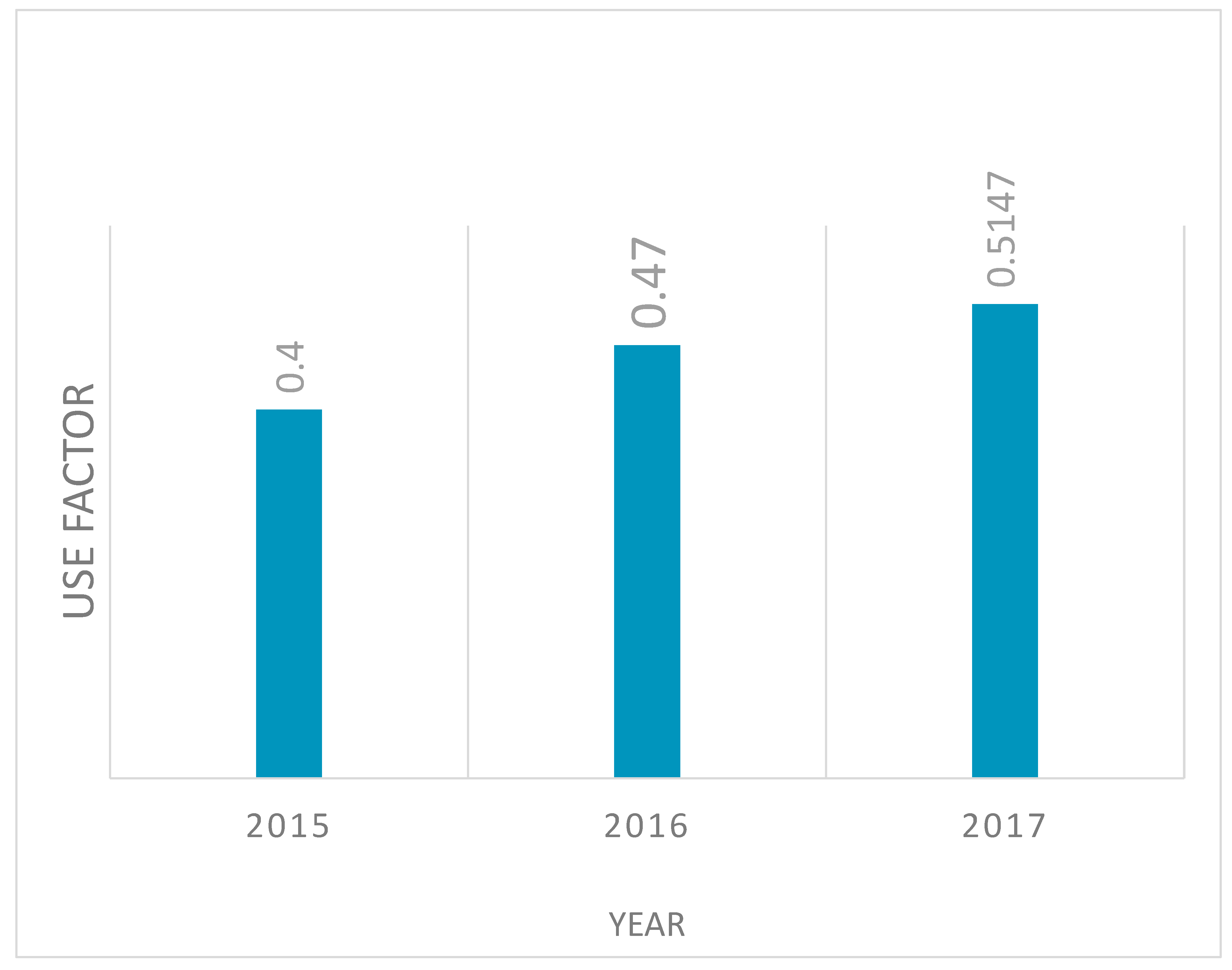
| Duration | 2015-2016 | 2016-2017 | 2017-2018 |
| Power generated | 525.6 GWh | 617.58 GWh | 675.5 GWh |
| Parameter | n-pentane | Iso-pentane | |
| 1 | Operating pressure (bars) | 15 | 18 |
| 2 | Mass flow rate of working fluid (kg/s) | 119.2 | 128.4 |
| 3 | Mass flow rate of cooling air | 1264 | 3176 |
| 4 | Evaporator area (m2) | 736.7 | 727.9 |
| 5 | Condenser area (m2) | 538.4 | 480.8 |
| 6 | Preheater area (m2) | 655.4 | 752.4 |
| 7 | Pump area (m2) | 969.2 | 615.5 |
| 8 | Fan area (m2) | 317.4 | 795.5 |
| 9 | Turbine work (kW) | 8585.2 | 7175.9 |
| 10 | Net work done (kW) | 7398.7 | 5764.9 |
| 11 | Cycle efficiency (%) | 13.9 | 10.1 |
| Component | N-pentene | Iso-pentane | |||||
| Size (m2) | Rate (USD) |
Total Cost | Size | Rate (USD) |
Total Cost | ||
| 1 | Preheater | 655.4 m2 | 450 | 294,930 | 752.4 m2 | 450 | 338,580 |
| 2 | Evaporator | 736.7 m2 | 500 | 368,350 | 727.9 m2 | 500 | 363,950 |
| 3 | Turbine work | 8585.2 kW | 450 | 3,863,340 | 7175.9 kW | 450 | 3,229,155 |
| 4 | Condenser | 538.4 m2 | 600 | 323,040 | 480.8 m2 | 600 | 288,480 |
| 5 | Feed pump | 969.2 kW | 450 | 436,140 | 615.5 kW | 450 | 276,975 |
| 6 | Cooling fan | 317.4 kW | 450 | 142,830 | 795.5 kW | 450 | 357,975 |
| 7 | Total | 5,428,630 | 4,855,115 | ||||
| 8 | Net power produced | 7398.7 | 5764.9 | ||||
| 9 | Specific cost of plant (USD/kW) | 733.7 | 842.2 | ||||
| Item | Total cost (USD) | Total cost (KES) | |
| Total cost of items | 5,275,210 | 527,521,000 | |
| Added project cost | 967,300 | 96,730,000 | |
| TOTAL | 6,242,510 | 624,251,000 | |
| ANNUAL REVENUE | |||
| Electricity produced in hour | cost of power/hr | Hrs/year | Revenue generated in a year |
| Revenue | 3 cents /kw/hr | 8760 | 97,218,392.4 |
| Pay Back Period Evaluation | |||
| Total cost/revenue generated | 627,751,000/97,218,392.4 | 6.42 = 6 Years 5 months | |
| The plant payback period is 6 years 5 months operating at 50% of the installed capacity | |||
| Criteria | Approach | |
| 1 | Price: | The price of the Organic fluids used affects the overall cost and preference should be fluids that have wider industrial applications which are generally cheaper. |
| 2 | Density of organic fluids | Generally, high density fluids are preferred to low density fluids. Low density fluids require higher volumetric flow rate which implies bigger size components which increases installation cost. There is however need for a tradeoff since high volumetric flow rate facilitate reduction of rotational speed of the expander which improves expander reliability. |
| 3 | Condensation pressure | The condenser should have a pressure as close as possible to the atmospheric pressure. This is because high condensation pressure technically increases system pressure which increases design cost. Too low pressure increases sealing needs and increases size of the condenser. |
| 4 | Freezing point | Freezing point should be below the minimum ambient temperature to avoid solidification of the working fluid especially during idle periods |
| 5 | Cycle top pressure | Top cycle pressure should be below the fluid critical pressure to prevent liquid droplets formation during expansion process and overcome instability during vaporization. This also reduces system cost in terms of design, operation, and maintenance costs. A trade-off must be found through a techno-economic analysis |
| 6 | Heat transfer coefficient | High heat transfer coefficient reduces surface area requirements hence the size of the installation as well as cost. |
| 7 | Decomposition temperature | The system and environmental temperatures should be lower than decomposition temperatures of the working fluids. |
| 8 | Molecular weight: | Working fluids with high molecular weight require less rotational speed of expanders which reduces generator cost. |
Disclaimer/Publisher’s Note: The statements, opinions and data contained in all publications are solely those of the individual author(s) and contributor(s) and not of MDPI and/or the editor(s). MDPI and/or the editor(s) disclaim responsibility for any injury to people or property resulting from any ideas, methods, instructions or products referred to in the content. |
© 2025 by the authors. Licensee MDPI, Basel, Switzerland. This article is an open access article distributed under the terms and conditions of the Creative Commons Attribution (CC BY) license (http://creativecommons.org/licenses/by/4.0/).


