
Submitted:
26 September 2025
Posted:
29 September 2025
You are already at the latest version
Abstract
Hydrogen embrittlement (HE) can degrade the mechanical integrity of steel pipes, increasing failure risks in naval fuel systems. This study assesses HE effects on ASTM A131 and A36 steels through tensile testing and numerical modeling. Tests at different hydrogen exposure times showed that A131 outperformed A36 in mechanical strength. However, both materials experienced property degradation after 6 hours. At 9 hours, a transient increase in strength occurred, due to temporary microstructural hardening, though the overall trend remained a decline. A131 and A36 exhibited maximum reductions in ultimate tensile strength of 19% and 47%, and in toughness of 39% and 61%, respectively. Additionally, microstructural analysis revealed the presence of inclusions, intergranular decohesion and micro-crack, in specimens exposed for longer periods. Finally, a combined GTN-PLNIH numerical model was implemented, demonstrating its effectiveness in predicting the mechanical behavior of structures exposed to hydrogen.
Keywords:
hydrogen embrittlement
; naval steels
; tensile tests
; microscopic damage detection
; FEM plasticity model
1. Introduction
The transition to renewable and sustainable energy has become a global priority to mitigate climate change and reduce dependence on fossil fuels. Green hydrogen has emerged as a key element in global energy sustainability strategies [1]. Although its production is still more expensive than that of grey hydrogen, the progressive reduction in renewable energy costs has opened up new opportunities for its competitiveness. However, to achieve the effective integration of hydrogen into a renewable energy matrix, challenges must be overcome in hydrogen production, transportation, and storage. Specifically, in the context of infrastructures intended for hydrogen transport and storage in maritime sector [2], which is the focus of this research, one of the main challenges is to ensure safe and reliable operation, avoiding any failure that could compromise structural integrity [3].
The high solubility of hydrogen in metals and alloys, such as ferritic steels used in pipelines, tubes, and pressure vessels, can cause severe degradation of the material’s mechanical properties, a phenomenon known as hydrogen embrittlement (HE) [4]. The hydrogen interacts with material defects, such as dislocations and grain boundaries, promoting the formation of microcracks that can lead to fracture [5]. Specifically, structural steels used in transmission pipelines and pressure vessels experience sudden and catastrophic failures after prolonged exposure to hydrogen, leading to serious implications in terms of safety, environmental impact, and economic repercussions. Therefore, hydrogen embrittlement has become a critical issue, intensely studied by the scientific community with the aim of developing effective solutions that ensure operational safety and reduce the costs associated with the development and maintenance of hydrogen transportation and storage infrastructure [6,7,8,9,10,11,12,13].
Given that theoretical methods are not sufficient to accurately predict the effects of hydrogen on these materials under real operational conditions, the need arises to conduct experimental studies and numerical simulations that directly assess the impact of hydrogen embrittlement on steel pipes [14] . In this context, this study aims to analyze the effects of HE on steel specimens through experimental and numerical methods to prevent potential structural collapse in steel pipes used in fuel systems in the naval sector. The findings of this work will enable researchers to evaluate new alloys and materials that promote the development of safe and sustainable renewable energy solutions.
2. Materials and Methods
This study analyzed hydrogen embrittlement in ASTM A131 and A36 steel specimens both experimentally and numerically. The experimental analysis was conducted through tensile tests performed on samples exposed to hydrogen for different time intervals. Based on these tests, the elastic and plastic mechanical properties of the steels were determined, allowing a quantitative evaluation of the effect of hydrogen on their structural behavior. Additionally, a metallographic analysis was carried out to visualize and microscopically characterize the hydrogen-induced embrittlement mechanisms. Finally, the results obtained experimentally were used to validate the developed numerical models, which accurately simulated the mechanical response of the materials until the ultimate load was reached.
2.1. Experimental Test
2.1.1. Specimen Construction
To reflect the real conditions of the steel pipes used in the fuel systems of the naval sector, ASTM A131 and A36 steel specimens were fabricated following the ASTM E8/E8M-08 standard [15]. Fifteen specimens of 4 mm thickness were made from the first steel type, which were used in the tensile tests with hydrogen exposure times of 0, 3, 6, 9, and 12 hours (3 specimens for each exposure time). The same procedure was followed for the second steel type, but with a thickness of 2 mm. The specimen dimensions, such as gauge length (G), width of effective length (w), radius of fillet (R), length of grip section (B), and width of grip section (C), are shown in Figure 1. The established design facilitated the hydrogenation of the material and proper execution of the tensile tests, allowing the analysis to focus on the area of interest, i.e., the effective length of each specimen.
2.1.2. Experimental Setting
Hydrogenation of steels
To achieve hydrogen insertion into the steel specimens, the constant current cathodic charging model [16] was applied. The specimens were immersed in a hydrochloric acid (HCl) solution with a concentration of 38%. A copper rod was used as the anode, and the steel specimens served as cathodes. A 220V-4A power supply was used to provide a current of 3.2 amperes, with the positive pole connected to wires arranged in series on the steel specimens and the negative pole connected to the copper electrode, as shown in Figure 2. The proper functioning of the electrolysis process was verified by the appearance of hydrogen bubbles in the solution. The atomic hydrogen generated by the reduction at the copper electrode penetrated the steel's metallic structure, promoting hydrogen embrittlement.
Tensile tests
After the steel specimens completed their hydrogen exposure time, extensometers were installed along the effective gauge length to record the strain and determine the Young's modulus of the materials. For this purpose, a National Instruments strain gauge register was used, connected to a computer running LabView software (see Figure 3). Additionally, the force and displacement during the tensile tests were recorded up to fracture using a Shimadzu universal testing machine, with a constant loading speed of 3 MPa/s for all specimens. These results allowed for the determination of both elastic and plastic mechanical properties of the steels.
Metallography method
After the steels were subjected to cathodic hydrogenation and tensile testing, metallographic specimens were prepared according to ASTM E3–95[17], which provides a systematic procedure for revealing, identifying, and analyzing the microstructure of metals. Initially, each specimen was selected and sectioned at a distance no greater than two centimeters from the necking zone, to ensure observation of the areas most affected by stress. Subsequently, the specimens were mounted in resin and meticulously polished to obtain a smooth surface that would not alter the internal microstructure. For phase revelation, a solution of nitric acid in alcohol was applied for five seconds, highlighting microstructural features. Finally, the specimens were examined under an optical microscope to identify phases, inclusions, and potential defects [18], with the information obtained correlated with the mechanical properties derived from the tensile tests.
2.2. Numerical Calculations
In this section, the computational package Ansys Workbench (version 2024 R2) was used. The Static Structural module was employed to simulate hydrogen embrittlement during tensile tests up to the ultimate load of the material. The models used for the plastic characterization of the material were the Power Law Nonlinear Isotropic Hardening (PLNIH) and the Gurson-Tvergaard-Needleman (GTN) Method [19]. The displacement approach was used, which iteratively applies the Newton-Raphson method until convergence is achieved [20]. The steps for the ultimate load analysis in Ansys Workbench include: definition of the elastic and plastic mechanical properties of the material, meshing, application of boundary conditions and loads, and ultimate load calculation [21].
2.2.1. Description of the Model
The geometry shown in Figure 1 was modeled using solid hexahedral elements. A mesh size of 10 mm was used for the length of the grip section, and a refined mesh of 1 mm was applied to the reduced parallel section, which is the region of interest. This meshing strategy was applied to both steels, as illustrated in Figure 4. Additionally, the applied boundary conditions can be observed: a fixed support at the lower end of the grip section and a controlled displacement at the upper end. These boundary conditions replicate the behavior of the experimental tensile test.
2.2.2. Description of Plastic Behavior of the Materials
The GTN model is combined with the PLNIH model to characterize the plastic behavior and damage evolution in ductile metals with porosity. In such cases, the material experiences void growth, nucleation, and coalescence. As porosity increases, material degradation intensifies, resulting in a reduced load-carrying capacity. The governing expressions of this combined model are presented below:
The GTN model is presented in Eq.(1), where σe, σy and p, denote the von Mises equivalent stress, yield stress, and hydrostatic pressure, respectively. The Tvergaard-Needleman constants were set as q1 =1.5, q2 =1.0, q3 =2.5 for ductile steels [22,23,24]. The modified void volume fraction f* is employed to represent the degradation in load-carrying capacity due to void coalescence. However, in this analysis, void coalescence was not considered, as the numerical simulations were carried out only up to the material's ultimate tensile strength.
Equation (2) presents PLNIH model, where σo, N represent the initial yield stress and the strain hardening exponent, respectively. These parameters were derived from the experimental tensile tests conducted as part of this study. The mechanical properties of ASTM A131 and A36 steels, as obtained from these tests, are summarized in Table 1 and Table 2. Additionally, the initial porosity f0 , included in the GTN model, accounts for hydrogen-induced voids, which have a significant effect on the mechanical behavior of the material.
The rate of change of void volume fraction is governed by two mechanisms: void growth and void nucleation, as described in Eq. (3). The first mechanism occurs when the solid matrix is subjected to a hydrostatic tensile state. Under such conditions, the increase in void volume fraction due to growth is proportional to the rate of volumetric plastic strain, as shown in Eq. (4). The second mechanism, void nucleation, takes place during plastic deformation when new voids are generated. In this study, void nucleation is modeled as a strain-controlled process, represented by Eq. (5). The nucleation parameters, mean strain εN =0.3 and standard deviation SN =0.1, were taken from experimental results [22,25].
3. Results and Discussion
To evidence HE in the steels, the dimensions of the specimens were recorded before hydrogen exposure and after the tensile tests. From these measurements, along with the force-displacement curves of each test, the elastic and plastic mechanical properties of the materials were obtained. The parameters considered included: Young’s modulus (E), yiel stress (σy), ultimate stress (σu), tenacidad (Ut) and ductility in terms of final elongation (Lf). This section presents the variation of mechanical properties due to HE in ASTM A131 and A36 steels. Tensile test results for A36 steel after 12 hours of hydrogen exposure are not shown, since one specimen exposed for 9 hours fractured prematurely during the cathodic charging process, before the tensile test could be performed, see Figure 5.
3.1. Experimental Analysis
The stress-strain curves for ASTM A131 and A36 steels subjected to different hydrogen exposure times of 0, 3, 6, 9, and 12 hours are shown in Figure 6. The strength of the steels decreases progressively with increasing hydrogen exposure time. As the hydrogen concentration in the specimens increases, the fracture stress is reached more quickly, indicating a degradation of their mechanical properties. Additionally, a loss of ductility is observed in both steels, with a more pronounced effect in A131 due to its higher strength. This behavior confirms the theory that high-strength steels are more susceptible to HE [26].
The yield stress and ultimate stress for each test are shown in Figure 7. For steel A131, a reduction of 4%, 12%, 7%, and 19% in ultimate strength and a reduction of 13%, 17%, 11%, and 25% in yield stress were observed after 3, 6, 9, and 12 hours of hydrogen exposure. For steel A36, a reduction of 30%, 47%, and 20% in ultimate strength and a reduction of 32%, 44%, and 19% in yield stress were observed after 3, 6, and 9 hours of hydrogen exposure. In the tests with 9 hours of hydrogen exposure, a temporary hardening was observed, attributed to the interaction between the hydrogen and the material’s microstructure. This behavior could be due to a temporary saturation effect, a transient hardening caused by hydrogen trapping in defects or dislocations, or a microstructural rearrangement, as suggested by researchers[7].
From the elastic region of the Stress-Strain curves in the tests, the slope data (Young's modulus) was extracted and are presented in Figure 8. The results show an increase in the elastic modulus of 4% and 9% for Steel A131 and A36, respectively, when the specimens were exposed to 3 hours in the aggressive environment. For the 6-hour exposure, a marked reduction in the Young's modulus was noted in comparison to the unhydrogenated specimens, with decreases of 6% and 16%, respectively. Subsequently, a decrease of 5% and 3% was observed for 9 and 12 hours of hydrogen exposure in Steel A131, and a 2% increase was seen for 9 hours of exposure in Steel A36. These variations in the Young's modulus can be attributed to the interaction between the hydrogen and the material’s microstructure, as previously mentioned.
The toughness of each specimen was obtained from the area under the Stress-Strain curve in Figure 6 and is presented in Figure 9. Although Steel A131 exhibits greater toughness compared to Steel A36, in both materials, this property gradually decreases after 6 hours of hydrogen exposure, with reductions of 14% and 61%, respectively. However, an increase in toughness is observed after 9 hours of hydrogen exposure. Despite this temporary variation, the long-term trend is decreasing, as evidenced in Steel A131 after 12 hours of hydrogen exposure, where the toughness is reduced by 30%.
The ductility of the steels, evaluated in terms of elongation, is shown in Figure 10. The greatest reduction was recorded in Steel A131 after 3 hours of hydrogen exposure, with a decrease of 28%, and in Steel A36 after 6 hours of hydrogen exposure, with a reduction of 26%. Overall, both materials show a progressive decrease in their plastic deformation capacity over time. However, Steel A36 maintains superior ductility, making it more suitable for structural applications subjected to prolonged exposure in hydrogen environments.
3.2. Metallographic Analysis
Microscopy images of the A131 steel specimens at 200x and 400x magnifications are presented in Figure 11. For the specimens without hydrogen exposure, the microstructure was predominantly composed of ferrite and pearlite, with a possible presence of bainite in higher-strength grades, as well as a non-uniform distribution of manganese sulfide (MnS) and complex oxide inclusions. In the specimens subjected to 3 hours of hydrogen charging, grain boundaries were not clearly distinguishable; however, two deep scratches were observed on the material surface, along with some visible inclusions. For the specimens exposed to hydrogen for 6 hours, the average grain size was 6.72 µm. Dark spots were observed, attributed to interactions between hydrogen and existing compounds or inclusions in the steel, such as oxides or carbides. In the specimens hydrogen-charged for 12 hours, elongated irregular grains were identified, likely due to plastic deformation, along with inclusions, intergranular decohesion, and micro-pitting. The presence of these defects provides clear evidence of hydrogen embrittlement in the material.
Microscopy images of the A36 steel specimens at 200x and 400x magnifications are presented in Figure 12. In the specimens without hydrogen exposure, a bimodal microstructure was observed, consisting of ferrite (light grains) and pearlite colonies (dark grains) heterogeneously distributed, with an average grain size of 9.93 µm. After 3 hours of hydrogen charging, the grain size increased to 16.89 µm, suggesting that hydrogen enhances grain boundary mobility by lowering the energy barriers that limit their movement, thus promoting the growth of larger grains at the expense of smaller ones. For the specimens subjected to 6 hours of hydrogen charging, the average grain size was 13.85 µm, and a more pronounced intergranular decohesion was observed, along with a brownish stain surrounding an inclusion, indicating possible metallurgical phenomena or localized chemical reactions. In the specimens exposed for 9 hours, the average grain size was 13.83 µm, with irregular grain morphology and elongated boundaries. Hydrogen diffusion into the material reduced atomic cohesion at grain boundaries, promoting the formation of coalescent micro-voids that facilitate intergranular fracture, thereby compromising the mechanical strength of steels used in naval applications.
3.3. Numerical analysis
To develop a model that accurately simulates the load and deformation behavior observed in the tensile tests, a comparison was made between the experimental and numerical results, as shown in Figure 13. In this analysis, the numerical model validation was performed using the stress-strain curves of ASTM A131 and A36 steels, exposed to hydrogen for 12 and 9 hours, respectively. By adjusting the parameters of the combined GTN-PLNIH model, a good match was achieved in the overall trend and behavior of the curves. However, a small gap was observed between the experimental and numerical curves in the region adjacent to the yield limit, which can be attributed to the strain hardening exponent, whose influence was not considered in this phase of the analysis.
Once the numerical model was validated, it was applied to the remaining numerical models, as shown in Figure 14. The stress vs. strain curves obtained up to the ultimate stress exhibit behavior similar to the experimental results. It is noteworthy that as the hydrogen concentration increases, the ultimate strength of the steels decreases proportionally. In the case of the models with a 9-hour exposure time, there is a deviation from this pattern, which could be due to the interaction between hydrogen and the grains of the material, according to researchers.
The initial porosity selected for each model, both with and without hydrogen exposure, plays a crucial role in determining the material's strength and ductility. When the initial porosity is higher, nucleation and coalescence of the voids occur more rapidly. As a result, the area under the curve in the plastic zone decreases, as shown in Figure 14. This is typical behavior for the loss of ductility and the onset of hydrogen embrittlement in the material.
The normal stresses in the "y" direction for the models A131_0H, A131_12H, A36_0H, and A36_9H are shown in Figure 15 and Figure 16. The results are displayed, when the ultimate stress of each model is reached. In all models, the onset of necking in the material is observed. This effect is more pronounced in the models without hydrogen exposure (zero initial porosity). Therefore, for the models with hydrogen exposure, the necking is less pronounced, highlighting the material's brittleness.
4. Conclusions
In this study, the effects of hydrogen on the naval steels ASTM A131 and A36 were investigated, with exposure to different hydrogenation times. Steel A131 exhibited superior mechanical properties compared to A36. However, both materials experienced a progressive decrease in their properties after 6 hours of hydrogen exposure. Notably, a transient increase in these properties was observed after 9 hours of exposure, attributed to a temporary hardening effect caused by the interaction between hydrogen and the material’s microstructure. Despite this isolated phenomenon, the long-term trend was generally decreasing. The maximum reduction in ultimate tensile strength was 19% for A131 steel and 47% for A36 steel. In terms of toughness, it decreased by 39% and 61%, respectively. These results demonstrate the detrimental effect of hydrogen on the structural integrity of these materials, particularly in industrial and maritime applications.
Microstructural analysis revealed defects in the material due to hydrogen embrittlement. Under magnification, the presence of inclusions, intergranular decohesion, cracks, micro-pitting, and fissures was observed, with a higher density in specimens exposed for longer times. These results emphasize the importance of developing mitigation strategies, such as protective coatings and optimized designs, to preserve structural integrity in industrial and marine applications exposed to corrosive conditions and hydrogen loading.
A combined GTN-PLNIH numerical model was implemented, which simulated the loading and deformation behavior in tensile tests of specimens with and without hydrogen exposure. The initial porosity induced by hydrogen was a critical parameter, as its increase accelerated void nucleation and coalescence, significantly reducing the material’s toughness and highlighting its brittleness. The model proved reliable for predicting the mechanical behavior up to ultimate load, making it a valuable tool for analyzing structures subjected to hydrogen-rich environments.
References
- The Committee on Industry Research and Energy of Europe, “Alternative and renewable energies,” 2020.
- De-Troya, J.J.; Álvarez, C.; Fernández-Garrido, C.; Carral, L. Analysing the possibilities of using fuel cells in ships. Int. J. Hydrogen Energy 2016, 41, 2853–2866. [Google Scholar] [CrossRef]
- Santana, L.; Pinto, D.L.; Osipov, N.; Furtado, J.; Bourguignon, F.; Marchais, P.-J.; Madi, Y.; Besson, J. Study of hydrogen embrittlement in steels using modified pressurized disks. Int. J. Hydrogen Energy 2024, 88, 498–514. [Google Scholar] [CrossRef]
- Dadfarnia, M.; Nagao, A.; Wang, S.; Martin, M.L.; Somerday, B.P.; Sofronis, P. Recent advances on hydrogen embrittlement of structural materials. Int. J. Fract. 2015, 196, 223–243. [Google Scholar] [CrossRef]
- Andeobu, L.; Wibowo, S.; Grandhi, S. Renewable hydrogen for the energy transition in Australia - Current trends, challenges and future directions. Int. J. Hydrogen Energy 2024, 87, 1207–1223. [Google Scholar] [CrossRef]
- Ruggieri, C.; Sarzosa, D.F.; Paredes, M. A local stress criterion to assess the effects of hydrogen embrittlement on the fracture strength of notched tensile specimens. Theor. Appl. Fract. Mech. 2023, 127. [Google Scholar] [CrossRef]
- Cao, J. Effect of hydrogen embrittlement on the safety assessment of low-strength hydrogen transmission pipeline. Eng. Fail. Anal. 2023, 156. [Google Scholar] [CrossRef]
- Shehata, M.; El-Shamy, A. Hydrogen-based failure in oil and gas pipelines a review. Gas Sci. Eng. 2023, 115. [Google Scholar] [CrossRef]
- Boukortt, H.; Amara, M.; Meliani, M.H.; Bouledroua, O.; Muthanna, B.; Suleiman, R.; Sorour, A.; Pluvinage, G. Hydrogen embrittlement effect on the structural integrity of API 5L X52 steel pipeline. Int. J. Hydrogen Energy 2018, 43, 19615–19624. [Google Scholar] [CrossRef]
- Bouledroua, O.; Hafsi, Z.; Djukic, M.B.; Elaoud, S. The synergistic effects of hydrogen embrittlement and transient gas flow conditions on integrity assessment of a precracked steel pipeline. Int. J. Hydrogen Energy 2020, 45, 18010–18020. [Google Scholar] [CrossRef]
- Zhang, R.; Ai, S.; Long, M.; Wan, L.; Li, Y.; Jia, D.; Duan, H.; Chen, D. Quantitative Study on Hydrogen Concentration–Hydrogen Embrittlement Sensitivity of X80 Pipeline Steel Based on Hydrogen Permeation Kinetics. Metals 2024, 14, 763. [Google Scholar] [CrossRef]
- Rivera-Vargas, G.A.; Matsumoto-Kuwabara, Y.; Baquero-Parra, R. Análisis para la obtención de hidrógeno a partir de biogás proveniente de la fermentación de bebidas naturales. 17. [CrossRef]
- Ghadiani, H.; Farhat, Z.; Alam, T.; Islam, A. Assessing Hydrogen Embrittlement in Pipeline Steels for Natural Gas-Hydrogen Blends: Implications for Existing Infrastructure. Solids 2024, 5, 375–393. [Google Scholar] [CrossRef]
- Garikoitz Artola Beobide, “Susceptibility to hydrogen embrittlement of high-strength steels: Behavior in marine environments and modeling of cracking patterns,” Universidad de Navarra, 2018.
- ASTM International, “Standard Test Methods for Tension Testing of Metallic Materials (E8/E8M – 08),” vol. 08, no. Reapproved 1989, pp. 3–4, 2000. [CrossRef]
- García, T.; Arroyo, B.; Rodríguez, C.; Belzunce, F.; Álvarez, J. Small punch test methodologies for the analysis of the hydrogen embrittlement of structural steels. Theor. Appl. Fract. Mech. 2016, 86, 89–100. [Google Scholar] [CrossRef]
- ASTM International, “Standard Practice for Preparation of Metallographic Specimens,” 1995.
- A.H. Committee, ASM Handbook: Metallography And Microstructures, vol. 9. 2004.
- Ansys, “Material Reference 2024R2.” pp. 13–345, 2024, [Online]. Available: http://www.ansys.com.
- Madenci, E.; Guven, I. The Finite Element Method and Applications in Engineering Using ANSYS®; Springer Nature: Dordrecht, GX, Netherlands, 2015. [Google Scholar]
- Mendoza, J.I.; Marín-López, J.R. Ultimate local strength of a submarine structure considering the influence of localized reduction of thickness. Ocean Eng. 2023, 271. [Google Scholar] [CrossRef]
- V. Tvergaard and A. Needleman, “Analysis of the cup-cone round tensile fracture,” vol. 32, no. I, pp. 157–169, 1984.
- Springmann, M.; Kuna, M. Identification of material parameters of the Gurson–Tvergaard–Needleman model by combined experimental and numerical techniques. Comput. Mater. Sci. 2005, 33, 501–509. [Google Scholar] [CrossRef]
- Vadillo, G.; Fernández-Sáez, J. An analysis of Gurson model with parameters dependent on triaxiality based on unitary cells. Eur. J. Mech. - A/Solids 2009, 28, 417–427. [Google Scholar] [CrossRef]
- Depraetere, R.; De Waele, W.; Hertelé, S. Fully-coupled continuum damage model for simulation of plasticity dominated hydrogen embrittlement mechanisms. Comput. Mater. Sci. 2021, 200. [Google Scholar] [CrossRef]
- Norman, E. Dowling, “Mechanical Behavior of Materials,” Fourth Edi., PEARSON, 2015, pp. 334–400.
Figure 1.
Specimen cutting plane for the experimental test.
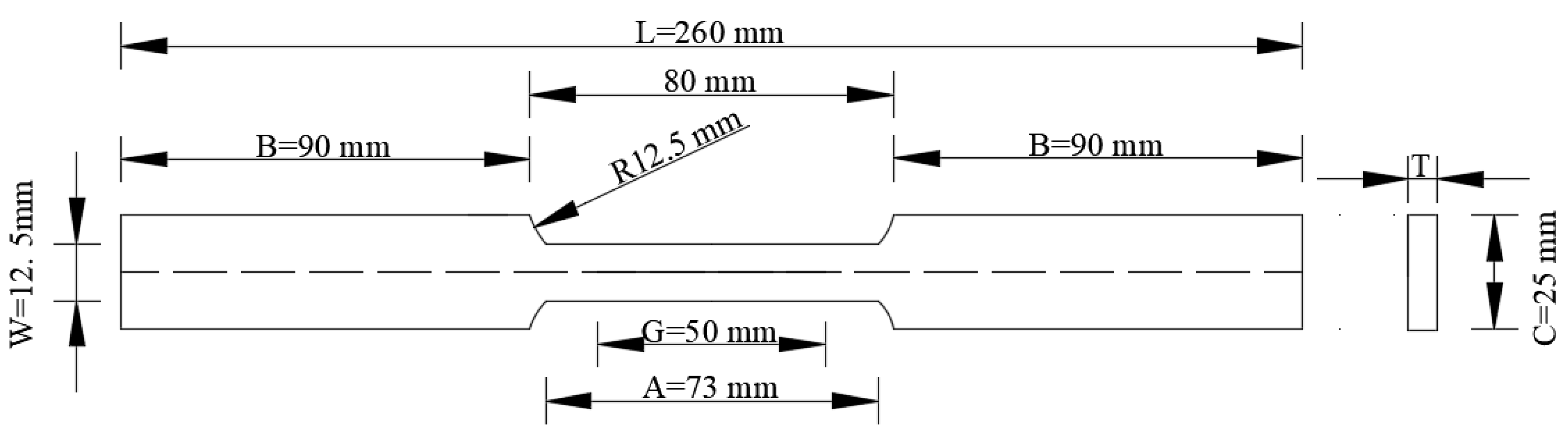
Figure 2.
Settings of the cathodic charge on the specimens.
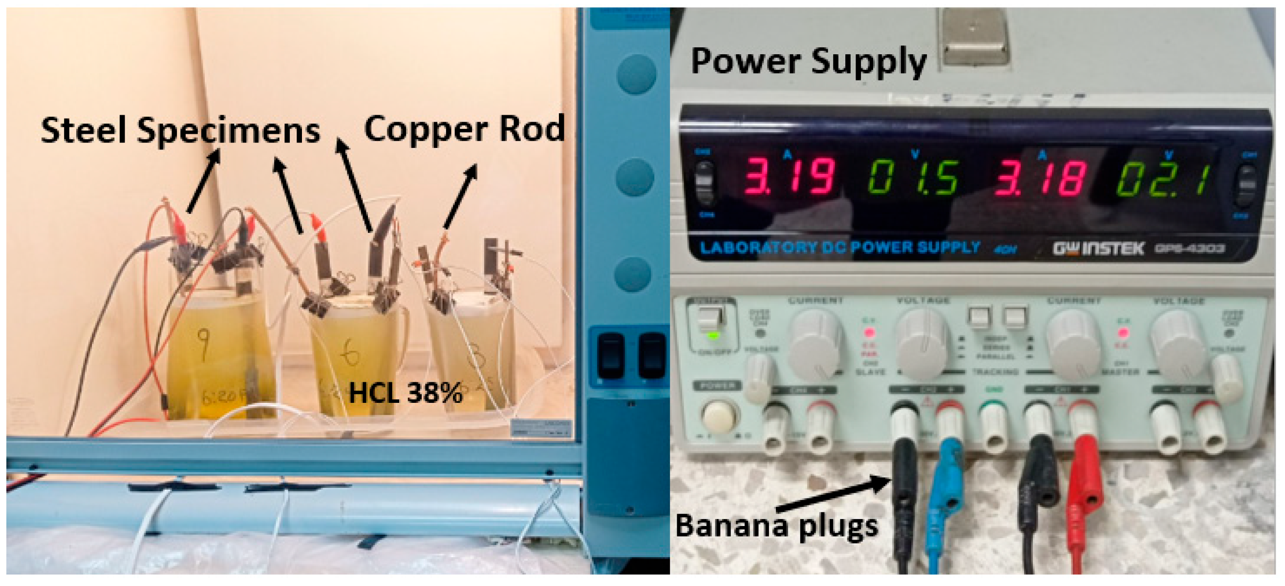
Figure 3.
Settings of the tensile test.
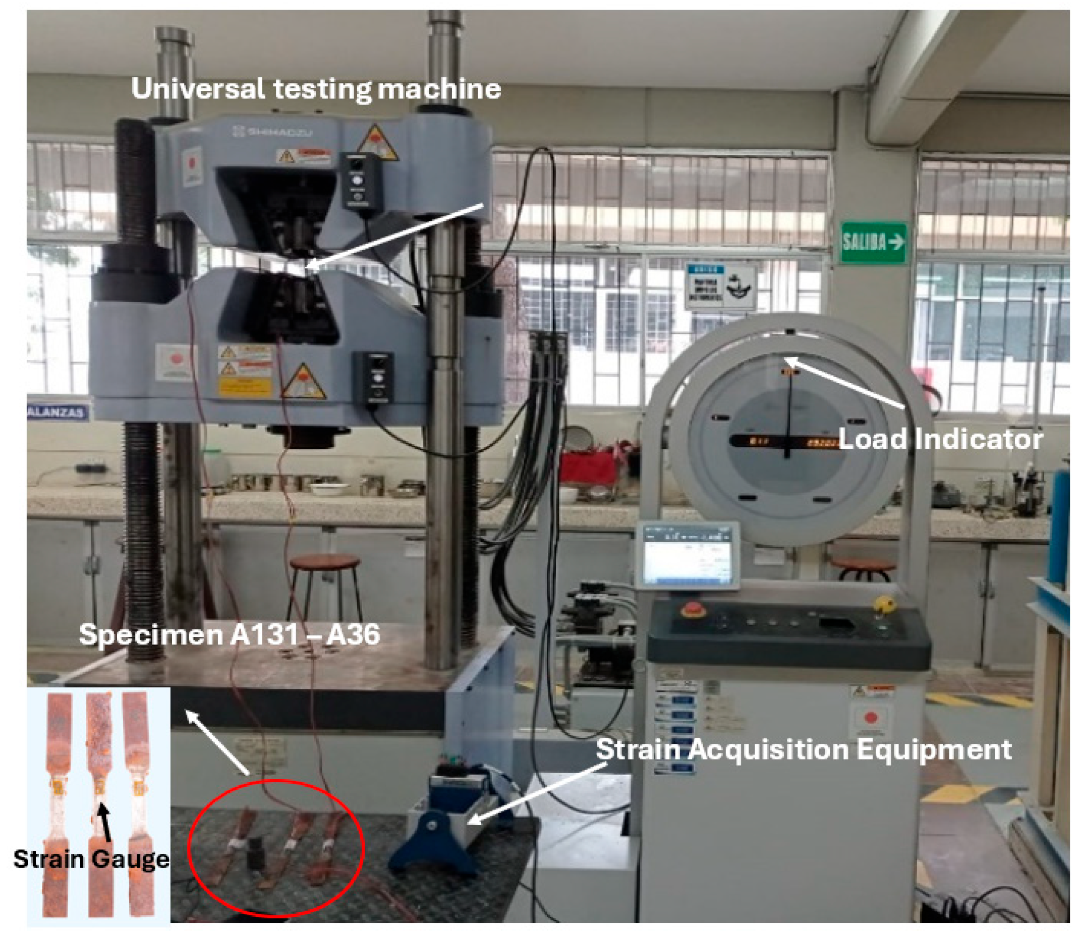
Figure 4.
Mesh, boundary condition and load of the models.
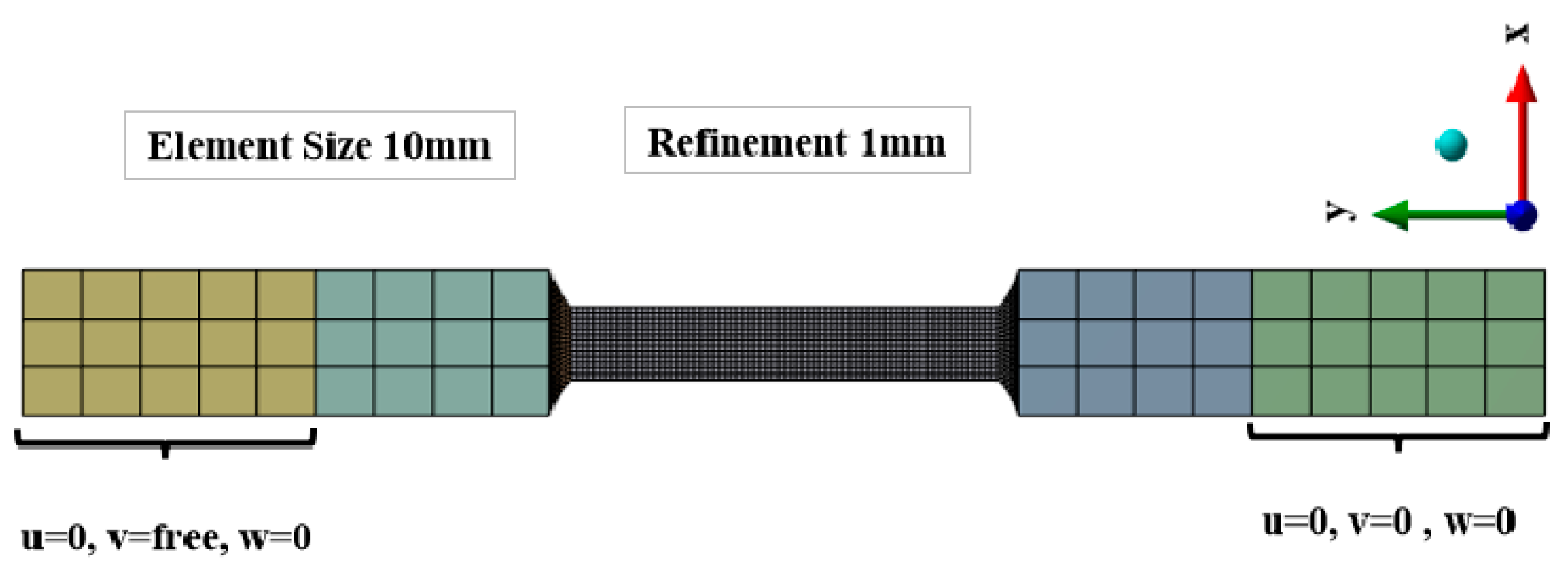
Figure 5.
Hydrogen embrittlement in Steel A36 at 9 hours.
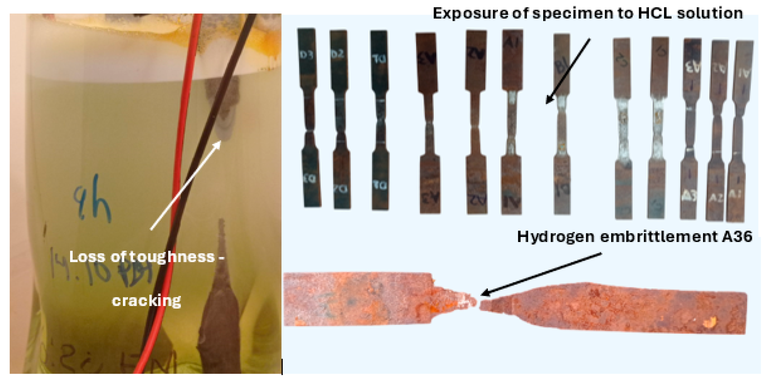
Figure 6.
Stress - Strain, Steel ASTM A131-A36.
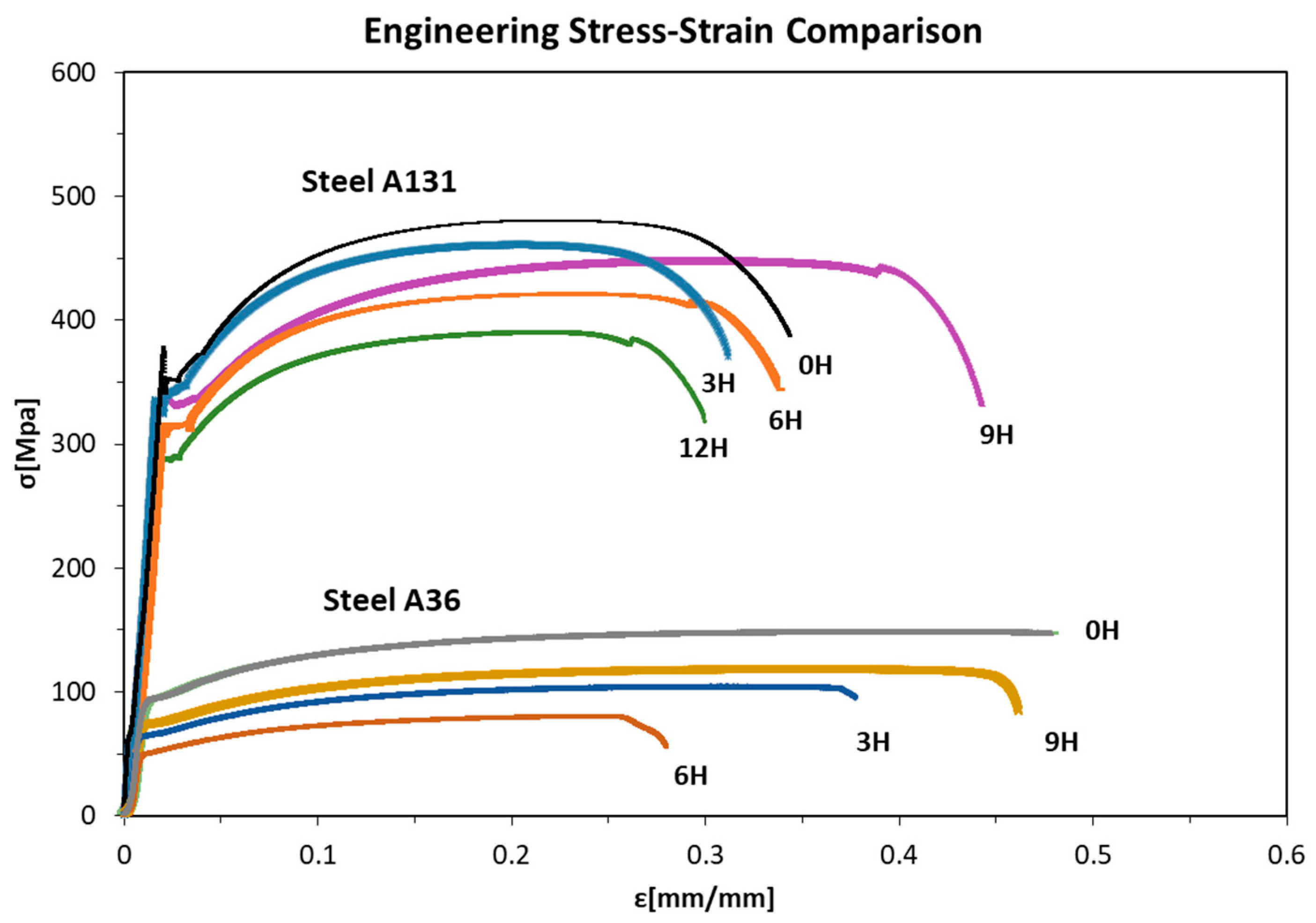
Figure 7.
Yield and Ultimate Stress of Steel A131-A36.
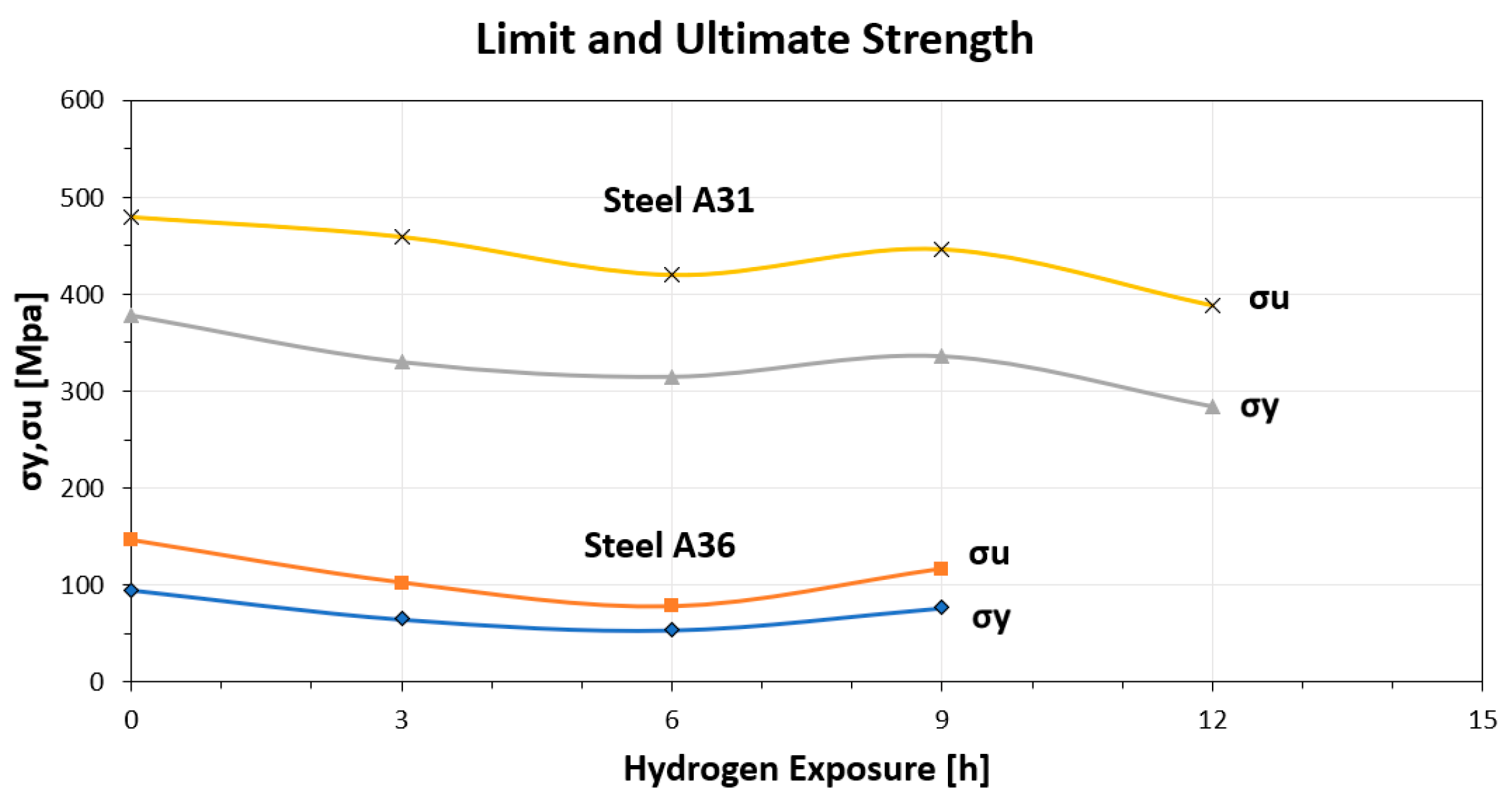
Figure 8.
Elasticity Modulus of steels A131-A36.
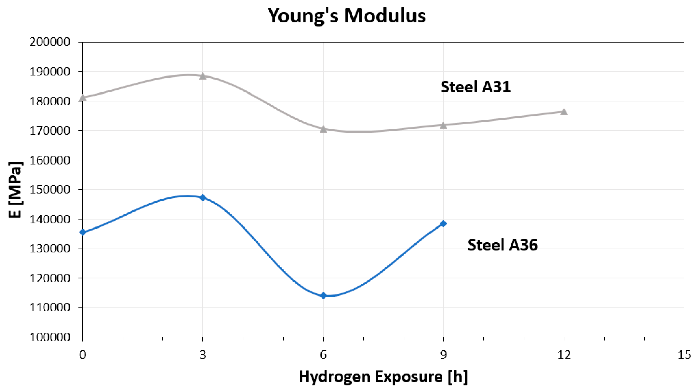
Figure 9.
Toughness of steels A131-A36.
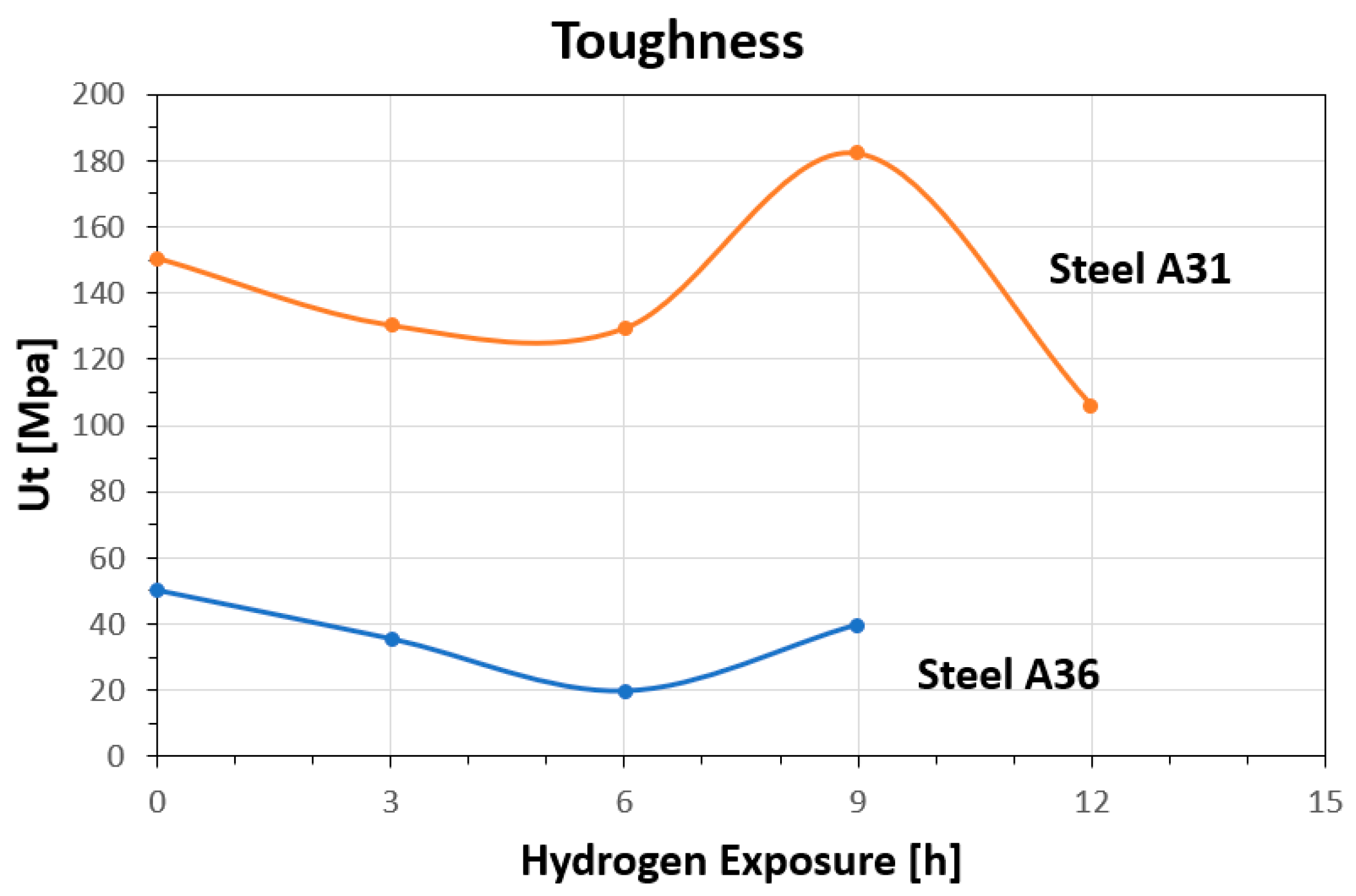
Figure 10.
Elongation of steels A131-A36.
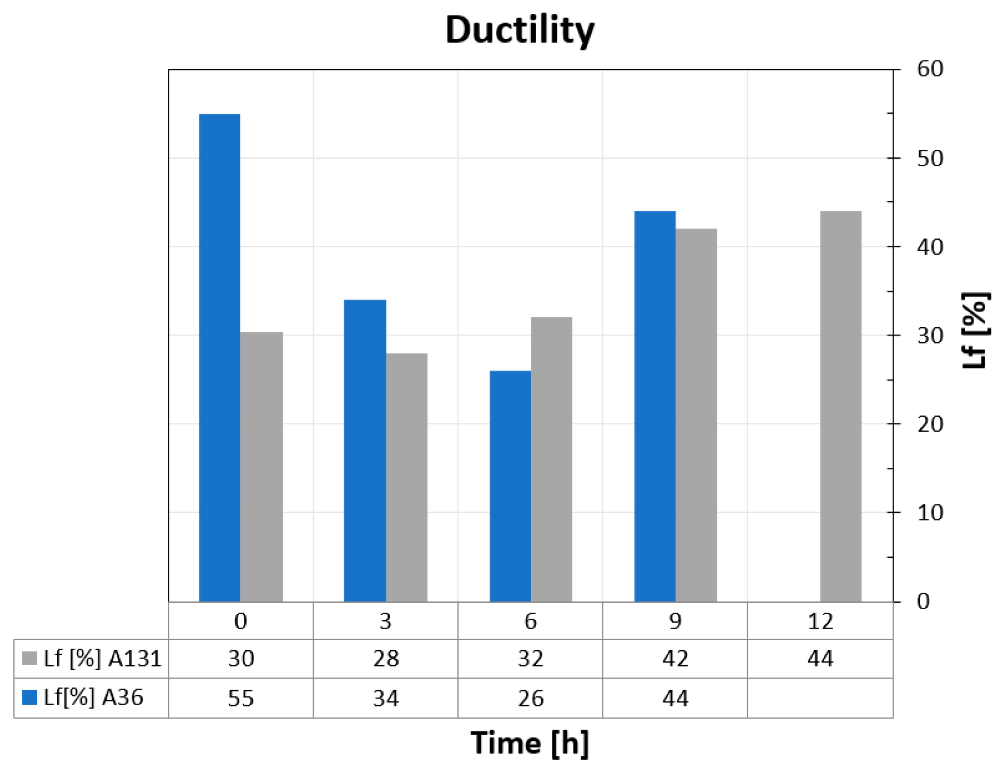
Figure 11.
Microscopy of A131 steel specimens.
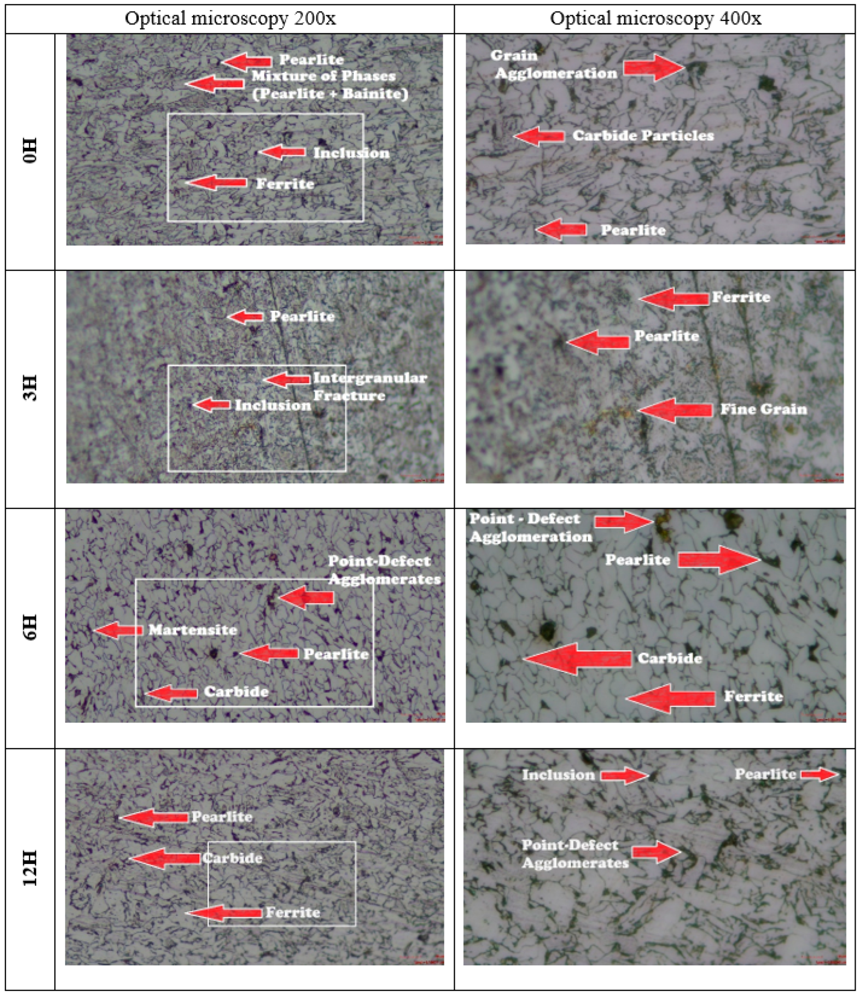
Figure 12.
Microscopy of A36 steel specimens.
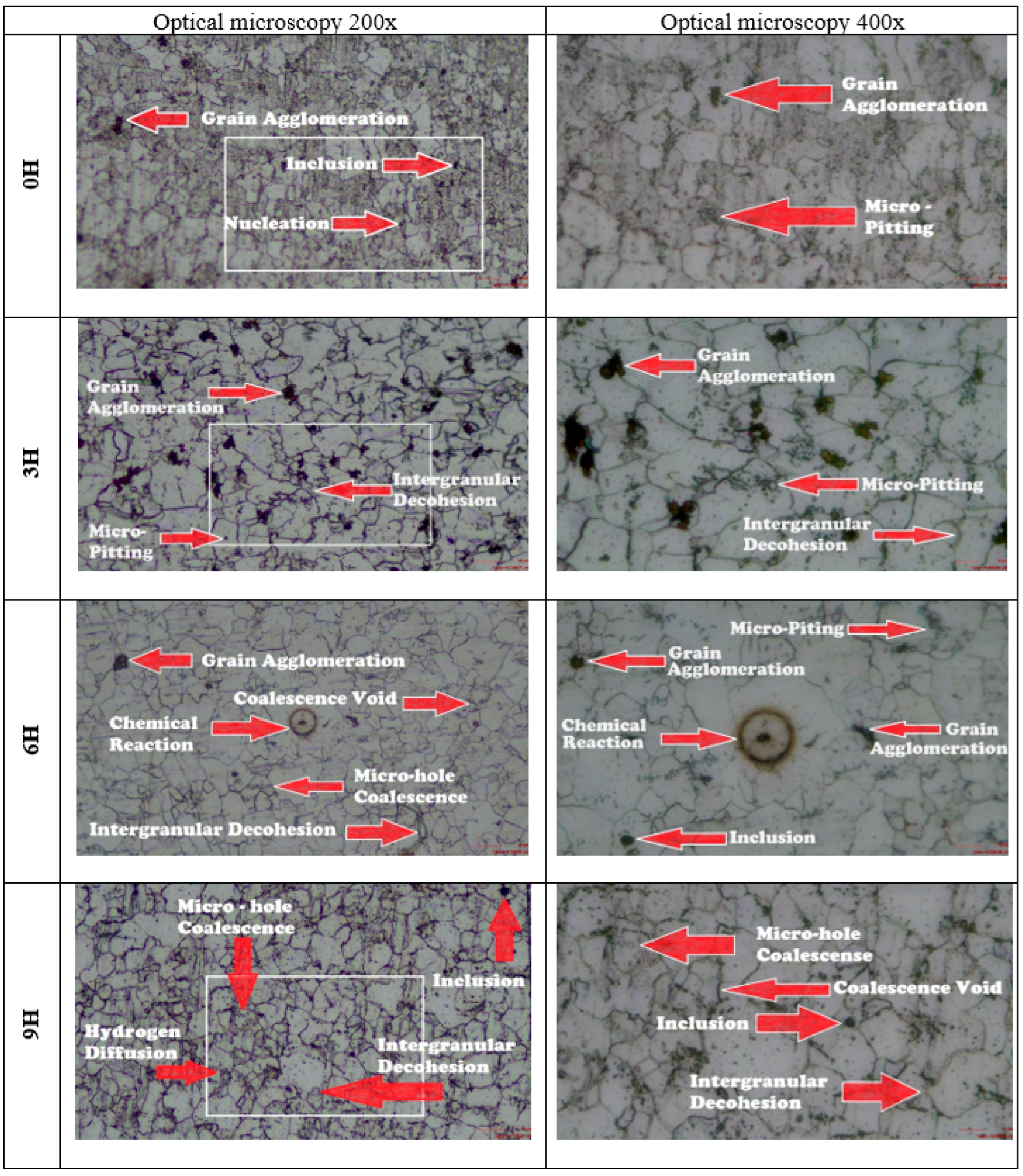
Figure 13.
Stress vs Strain numerical-experimental comparison.
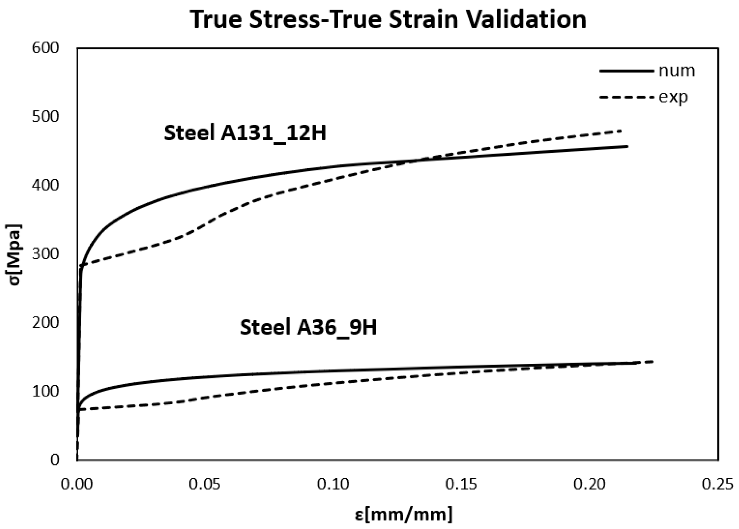
Figure 14.
Influence of hydrogen in steel.
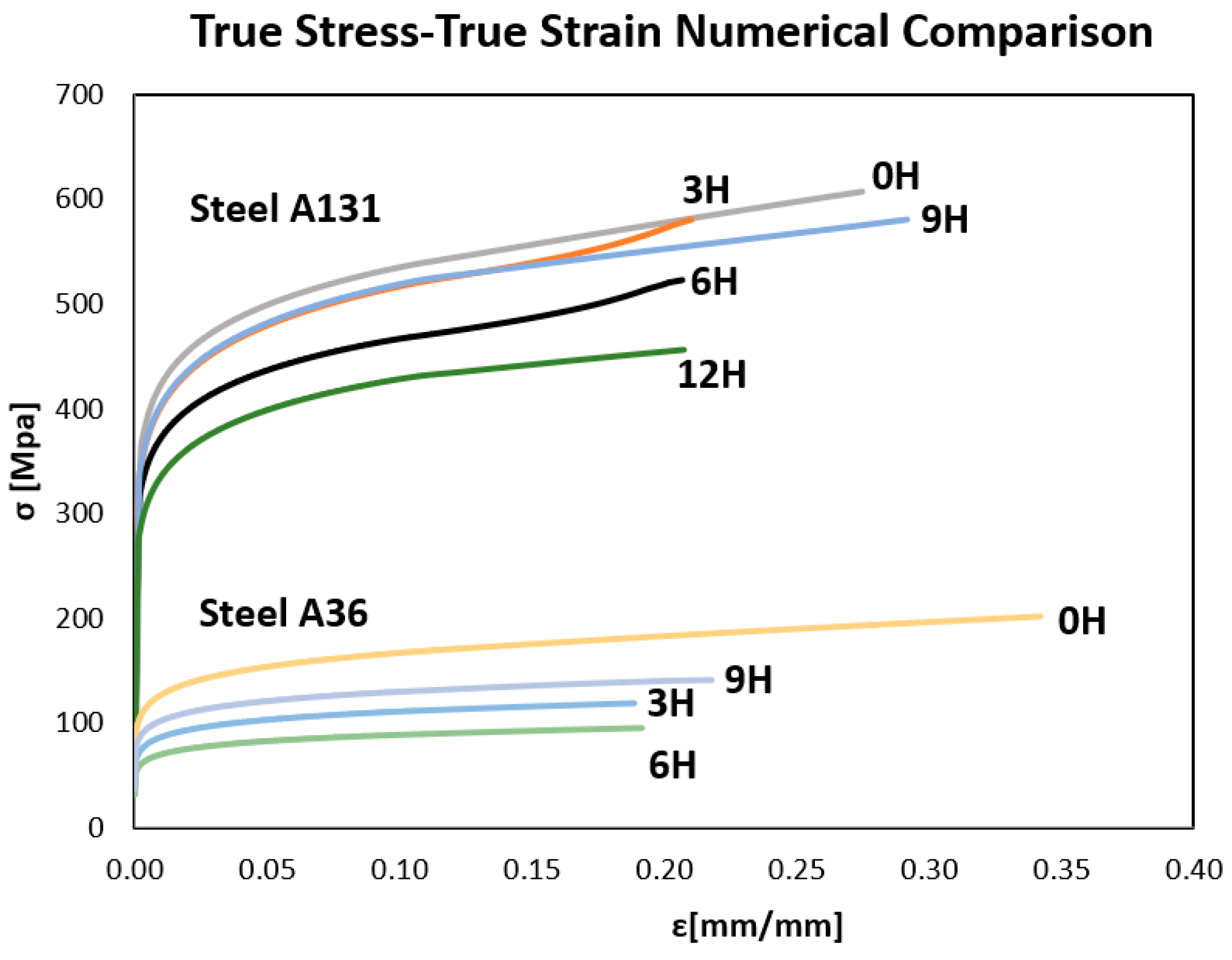
Figure 15.
Normal Stress in “y” direction of Steel A131.
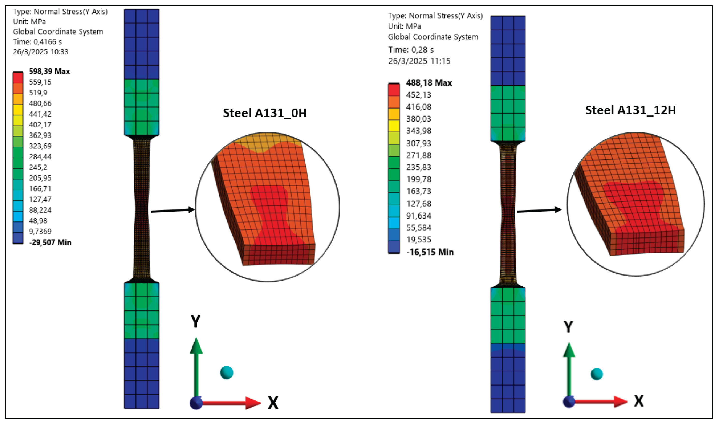
Figure 16.
Normal Stress in “y” direction of Steel A36.
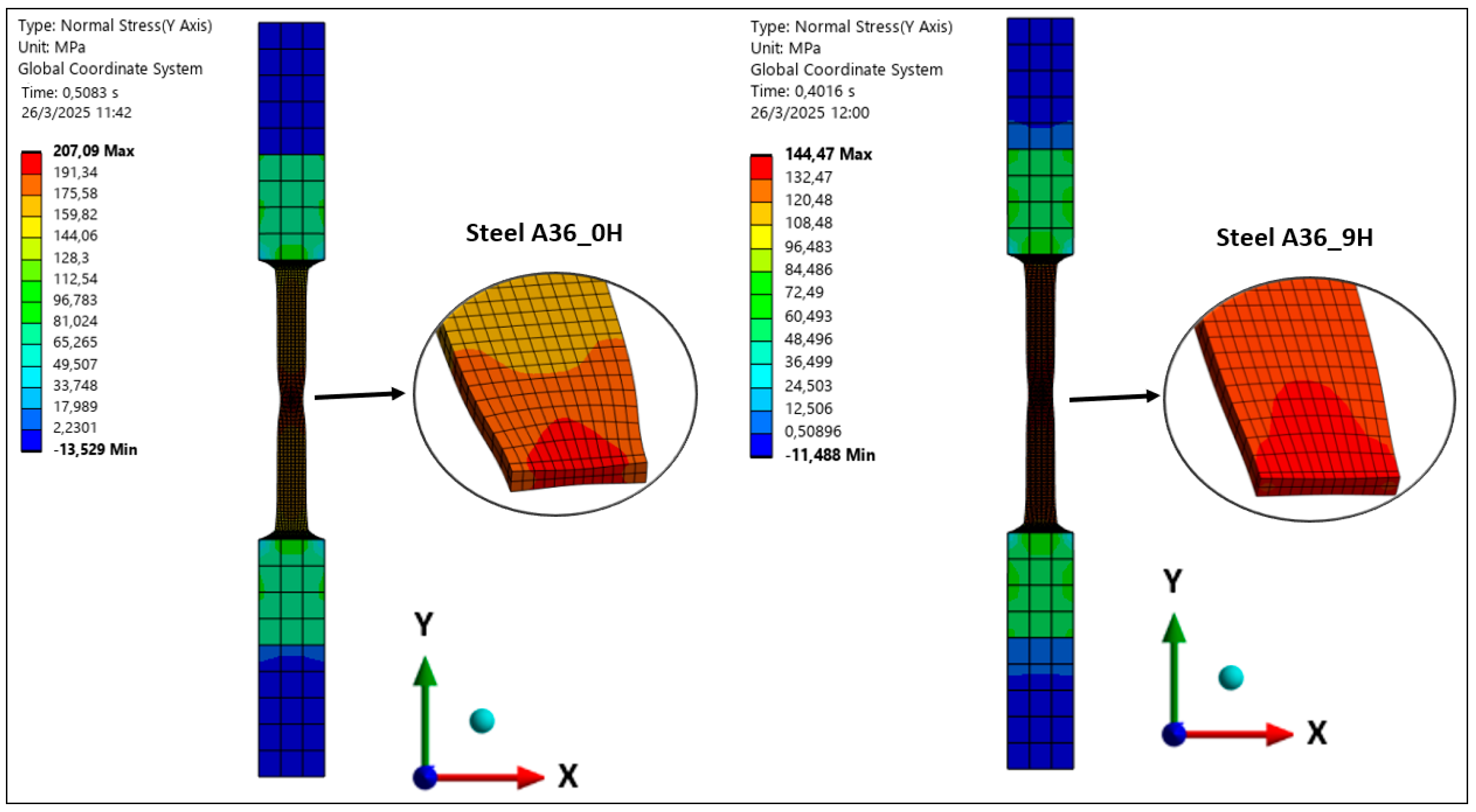

Table 1.
Mechanical Properties of A131 Steel.
| Exp. time | 0 H | 3H | 6H | 9H | 12H |
|---|---|---|---|---|---|
| E [Mpa] | 181776.7 | 188973.8 | 171075.2 | 172392.7 | 176830.2 |
| σo[Mpa] | 352.6 | 329.4 | 314.1 | 335.78 | 284.6 |
| n | 0.10 | 0.11 | 0.10 | 0.11 | 0.11 |
| σu[Mpa] | 592.5 | 565.1 | 518.0 | 598.4 | 479.2 |
| f0 | 0.000 | 0.004 | 0.008 | 0.006 | 0.03 |
Table 2.
Mechanical Properties of A36 Steel.
| Exp. time | 0 H | 3H | 6H | 9H |
|---|---|---|---|---|
| E [Mpa] | 135695.0 | 147320.8 | 114118.4 | 138629.9 |
| σo[Mpa] | 90.1 | 59.9 | 49.6 | 74.52 |
| n | 0.12 | 0.11 | 0.11 | 0.11 |
| σu[Mpa] | 205.2 | 121.0 | 94.9 | 162.3 |
| f0 | 0.000 | 0.024 | 0.0021 | 0.0011 |
Disclaimer/Publisher’s Note: The statements, opinions and data contained in all publications are solely those of the individual author(s) and contributor(s) and not of MDPI and/or the editor(s). MDPI and/or the editor(s) disclaim responsibility for any injury to people or property resulting from any ideas, methods, instructions or products referred to in the content. |
© 2025 by the authors. Licensee MDPI, Basel, Switzerland. This article is an open access article distributed under the terms and conditions of the Creative Commons Attribution (CC BY) license (http://creativecommons.org/licenses/by/4.0/).
Copyright: This open access article is published under a Creative Commons CC BY 4.0 license, which permit the free download, distribution, and reuse, provided that the author and preprint are cited in any reuse.


