
Submitted:
25 September 2025
Posted:
26 September 2025
You are already at the latest version
Abstract
Growing environmental awareness has renewed interest in thorium as a nuclear fuel, underscoring the need for further studies to evaluate how reactors perform when conventional fuels are replaced with thorium-based alternatives. In this work, thermal-hydraulics, and solid mechanics computations were simulated using COMSOL multiphysics to investigate the safe operating conditions of heavy water reactor with thorium-based fuel. The thermo-mechanical analysis of the fuel rod under transient heating conditions provides critical insight into strain, displacement, stress, and coolant flow behavior at elevated volumetric heat sources. After 3 s of heating, the strain distribution in the fuel exhibits a high-strain core surrounded by a low-strain rim, with peak volumetric strain increasing nearly linearly from 0.006 to 0.014 as heat generation rises. Displacement profiles confirm that radial deformation is concentrated at the outer surface, while axial elongation remains uniform and scales systematically with power. The resulting von Mises stress fields show maxima at the outer surface, increasing from ~0.6 to 1.5 GPa at the centerline with higher heat input, but remaining within structural safety margins. Cladding simulations demonstrate nearly uniform axial expansion, with displacements increasing from ~0.012 mm to 0.03 mm across the investigated power range and average strain remains negligible (≈10⁻⁴), while mean stresses increase moderately yet stay well below the yield strength of zirconium alloys, confirming safe elastic behavior. Hydrodynamic analysis shows that coolant velocity decreases smoothly along the axial direction but maintains stability, with only minor reductions under increased heat sources. Overall, the coupled thermo-mechanical and fluid-dynamic results confirm that both the fuel and cladding remain structurally stable under the studied conditions. By using COMSOL’s multiphysics capabilities, and unlike most legacy codes optimized for uranium-based fuel, this work is designed to easily incorporate non-traditional fuels such as thorium-based systems, including user-defined material properties, temperature-dependent thermal polynomial formulas, and mechanical response.
Keywords:
thorium-based fuel
; thermal-hydraulics
; solid mechanics
1. Introduction
Thorium has been viewed as a prospective reactor fuel since the nuclear power sector emerged in the 1950s, yet—despite worldwide initiatives—its advancement has consistently lagged behind that of uranium-based fuels. Today, interest in thorium has been risen again due to the drive to develop safe, clean nuclear fuels capable of addressing modern power generation challenges, and its abundant reserves further underscore its potential to meet the rising global demand for energy [1,2]. Consequently, significant research has focused on investigating the replacement of uranium fuel with thorium as a means to reduce reliance on the scarce uranium fuel. Monte Carlo N-Particle eXtended (MCNPX) code version 2.7, with the ENDF.VII cross-section library, was used to study the neutronic performance of thorium-based fuel types [(0.944Th, U)O₂, (0.955Th, ²³³U)O₂, and (0.934Th, rgPu)O₂] as alternatives to UO₂. The study demonstrated good viability by achieving acceptable safety parameter values and providing a favorable power distribution throughout the fuel assembly compared to UO₂ [3]. Incorporating 15% TRUO₂ into an 85% Th-233UO₂ fuel for Pebble Bed Modular Reactor (PBMR-400) optimizes neutronic performance by extending the fuel cycle, offer potential waste reduction and show good environmental benefits [4]. Using a 3D heterogeneous MCNPX model, the study evaluated thorium fuel for the Gas Cooled Fast Reactor (GCFR-400) found that the proposed fuel exhibits promising neutronic performance with satisfactory control and safety parameters throughout its burnup [5]. Thorium-based fuels—whether blended with High Enriched Uranium (HEU), Low Enriched Uranium ( LEU), or ²³³U or formulated as MOX/mononitride—deliver acceptable thermal neutron fractions for flat power density, lower fuel temperatures, improved reactivity coefficients, reduced plutonium and minor actinide production, and enhanced proliferation resistance [6,7,8,9,10]. The analysis of (ThxU₁₋ₓ)N fuel in both infinite and compact reactor models indicates that thorium additions maintain criticality, extend reactor service life by reducing keff decline and enhancing ²³³U production and introduce a potential diversion risk due to proliferation vulnerabilities [11]. Based on state-of-the-art reactor designs, it is concluded that thorium-based molten salt small modular reactors represent the most promising technical pathway to advance nuclear energy into a new era—meeting market demands while ensuring maximum safety at an affordable capital cost [12].
Designing a reactor core that meets operational requirements remains one of the most significant challenges in reactor physics, where the quest for effective core optimization methods that ensure safety and improve economic efficiency has long been a central focus. Additionally, simulating nuclear fuel behavior is crucial for licensing and interpreting experiments with new fuels, as it involves evaluating temperature distributions, velocity profile and stresses. Finite Element Modeling (FEM) plays an improtant role in the design, safety analysis, and operation of nuclear reactors, because it incorporates multiple physics modules such as thermal, structural, and fluid flow. A fully coupled, time-dependent multi-physics model was developed using COMSOL Multiphysics to analyze the single-channel behavior of a Lead Fast Reactor (LFR) under both steady-state and transient conditions [13]. The model integrated neutronics, thermal-fluid dynamics, and thermal-elastic effects, enabled accurate prediction of reactivity feedbacks without relying on corrective factors, and was validated against Monte Carlo simulations using SERPENT. SERPENT is a 3D, continuous-energy Monte Carlo code for neutron and photon transport, developed at VTT Technical Research Centre of Finland since 2004. It supports stand-alone burnup simulations, lattice physics, group-constant generation, and multi-physics coupling for reactor analysis, shielding, fusion applications, and more. A steady-state thermal–mechanical safety analysis of a 0.5 MWth heat pipe-cooled, graphite-moderated micro reactor were provided using ANSYS Fluent and ANSYS Mechanical, focusing on temperature, heat pipe loads, and structural stresses during normal operation and heat pipe failure scenarios. The analysis showed that the design remains within safety limits under most conditions, and two design modifications were proposed—thermal paste and non-uniform heat sink conditions—to reduce thermal stresses in critical failure cases [14]. A two-dimensional thermomechanical-coupling model of a heat-pipe-cooled space-reactor core was built in COMSOL multiphysics to calculate key heat-transfer and structural-mechanics parameters under both steady-state and accident conditions and to evaluate the core’s thermal safety performance. The analysis shows that failure of a single heat pipe at any location poses no safety risk. However, thermal stress exceeds the allowable limit if two heat pipes fail at the core edge, and with three failed heat pipes it surpasses the limit even in the well-cooled central region, raising the local maximum temperature to 1959.8 K [15,16]. Coupled neutronics, thermal-hydraulics, and thermo-mechanics steady-state COMSOL analysis of a molten salt fast reactor enabled an accurate assessment of reactivity feedbacks and fuel behavior in a fully liquid-fueled fast reactor configuration[17,18]. Although extensive thermal-hydraulic and solid mechanics safety analyses have been conducted for CANDU-6 reactors—as shown in studies on pressure tube creep effects, critical channel power reduction, and high-temperature deformation behavior [19,20,21,22]—there remains a compelling need to provide new and updated safety studies. For instance, existing models often rely on historical creep correlations and coolant behavior under idealized or steady-state conditions. However, evolving reactor operation strategies and potential introduction of alternative fuels such as thorium demand a reassessment of heat transfer, mechanical stress, and safety margins. Studies like those evaluating thorium-based fuel channels (e.g., TACR-1300) demonstrate promise but remain limited to preliminary or simplified models, lacking full multi-physics coupling or transient condition analysis. Furthermore, modern computational tools such as COMSOL Multiphysics or advanced Computational Fluid Dynamics solvers can now incorporate temperature-dependent material properties and real-time coolant property variations more accurately.
In this study, COMSOL multiphysics was employed to carry out coupled thermal-hydraulic and structural analyses, evaluating the safe operating limits of a heavy-water reactor fueled with thorium. A transient model combined the Heat Transfer in Solids and Fluid Flow interfaces for heat-conduction and fluid-dynamics calculations, and the Solid Mechanics interface for the structural response. The simulations produced temperature fields, pressure and velocity distributions, as well as displacement, strain, and geometric deformation results.
2. Materials and Methods
Thermal-hydraulic and solid-mechanics calculations can be performed using the radial power distribution obtained from the neutronic analysis. The results of the neutronic calculations reported by [23] were used as input for our calculations. The reactor core is housed within a horizontal cylindrical vessel made of stainless steel. Inside this vessel are 380 fuel channels submerged in heavy water, which serves as a neutron moderator. The fuel channels are arranged in a square lattice with a spacing of 28.575 cm (Figure 1). Each channel includes a pressure tube made of zirconium–niobium alloy, encased within a zircaloy-2 calandria tube, and connected at both ends by stainless-steel fittings. Spacers are used to support the pressure tube and maintain its separation from the calandria tube. The space between these tubes is filled with carbon dioxide gas, serving as thermal insulation to reduce heat loss. Every fuel channel holds 12 identical fuel bundles, each 49.53 cm long, with each bundle containing 37 fuel rods arranged in a circular ring configuration. Each fuel rod consists of 30 fuel pellets enclosed within a cladding tube made of zirconium alloy. The design parameters and dimensions of reactor core can be found from Table 1.
Because all fuel bundles and channels in the core are symmetrical, a single fuel bundle was modeled to represent the neutronic behavior of the fuels under investigation. Figure 2 illustrates Pin power distribution through fuel bundle, which is obtained from neutronics calculations.
From the power distribution, we can identify the hottest rod, where the most limiting and safety-critical conditions in the reactor core are present. The aim is to demonstrate these conditions through simulations. For comparison, single fuel rods operating at the maximum, median, and minimum power levels were individually analyzed (Table 2). The initial step in the solution process involves breaking down the geometry into smaller elements, a procedure known as meshing. After that, the partial differential equations (PDEs) are mapped onto this mesh. Free triangular fine mesh was used for simulations and presented in Figure 3. The reason for using triangular elements is that they can conform more easily to complex geometries, such as curved boundaries, fuel rods, cladding layers, and coolant channels. Therefore, triangular meshes adapt better than quadrilateral meshes.
(Th, 233U)O2 was selected as the fuel, and its relevant physical properties were taken from the literature. COMSOL Multiphysics can integrate heat-transfer, fluid-dynamics, and solid-mechanics physics into a single model. This multiphysics coupling offers the most faithful representation of real-world behavior, requiring far fewer simplifying assumptions than typical analytical approaches. Three physics modules are used as the following:
2.1. Heat Transfer in Solids
The heat-generation PDE is addressed with the FEM. Since a thermal power used for the heating cross surface of the core, the transient Fourier heat conduction equation was solved to find the spatial distribution of temperature. The PDE is then discretized over the mesh, and solving it provides the temperature distribution within the fuel, cladding, and coolant. Except the top, bottom and cross surfaces, all other boundaries are assumed to be thermally insulated.
Specific heat capacity of (Th, 233U)O2:
Thermal conductivity of (Th, 233U)O2:
Density of (Th, 233U)O2:
Specific heat capacity of zircalloy-4:
Thermal conductivity of zircalloy-4:
Density of zircalloy-4:
2.2. Fluid Dynamics
The Navier–Stokes PDE for momentum and mass conservation are solved, yielding the pressure drop of the coolant along the axial (z) direction and the corresponding velocity field. When this turbulent-flow (k–ω) model is coupled with the heat-transfer physics, two key outputs emerge: 1)The convective heat-transfer coefficient h, which depends on the coolant velocity, the channel geometry (velocity-independent), and the temperature-dependent coolant properties, 2)The axial pressure drop obtained from the Navier–Stokes solution. Combining this pressure drop with the temperature profile and local heat flux from the heat-generation equation makes it possible to evaluate the coolant’s distance from nucleate-boiling conditions at any location along the z-axis. The water inlet and outlet boundaries are the top and bottom surfaces, respectively.
2.3. Solid Mechanics
Within the solid-mechanics interface, the model solves the governing elasticity equations (analogous to Navier–Stokes for solids) to determine the thermal-induced deformation, displacement magnitude, and strain in the fuel and cladding, fully coupled to the heat-transfer physics. Top and bottom boundaries are fixed to reflect the physical constraints imposed by the reactor’s structural support system.
For mechanical properties, the following thermal expansion expressions for fuel [26] and clad [24] were used:
Young’s Modulus expressions for fuel and clad materials [24]:
The effects of burn-up, plutonium content, pellet cracking, swelling, oxygen-to-metal ratio, and gaseous fission product release on the thermal properties of the fuel are neglected. It is known that elementary particle irradiation affects the mechanical and structural properties of materials [27,28,29]. In this work, irradiation effects are also neglected due to the lack of available literature data.
3. Results and Discussion
To ensure safe reactor operation, the fuel’s centerline temperature must remain below its melting point, and its average temperature must stay under 1400 °C [30]. The spatial distribution of temperature after application of the maximum heat source for different times(from 0 to 3 seconds) is shown in Figure 1a. When the heat is transferred from the inner surface of the fuel material to its outer, the temperature changes parabolically. The temperature profile along the y–x direction is presented in Figure 1b. As evident from the figure, the reactor core exposed to a heat source for a longer period attains a higher temperature than when the exposure time is shorter. A similar temperature increase in the fuel and cladding materials as a function of time was also observed in the coupled neutronic, thermo-elastic, and fluid-dynamic time-dependent model for the single-channel transient analysis of a Lead Fast Reactor [13].
Figure 1.
The temperature distribution through different materials of the fuel rod after application of the maximum heat source for different times(from 0 to 3 seconds) (a). The temperature profile along the y-x direction (b). 0 s means the beginning of the simulation time.
Figure 1.
The temperature distribution through different materials of the fuel rod after application of the maximum heat source for different times(from 0 to 3 seconds) (a). The temperature profile along the y-x direction (b). 0 s means the beginning of the simulation time.
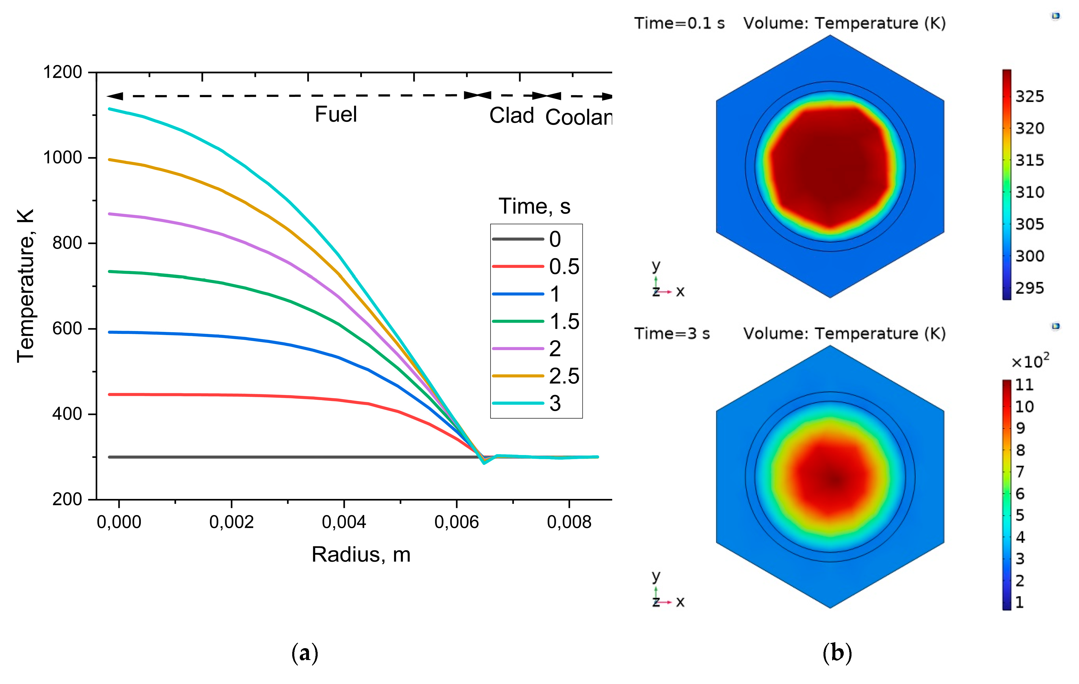
Figure 2 demonstrates the temperature values at 3 s after applying the maximum, median, and minimum heat sources. Overall, the temperature decreases radially from the center of the fuel rod to the coolant boundary. The centerline and average fuel temperatures are below the safety limit. A similar radial temperature distribution in the fuel rod, with a further decrease in the cladding, was observed in the thermo-mechanical analysis of a heat pipe–cooled space reactor [15].
Figure 2.
Radial temperature distribution at 3 s after applying the maximum, median, and minimum heat sources.
Figure 2.
Radial temperature distribution at 3 s after applying the maximum, median, and minimum heat sources.
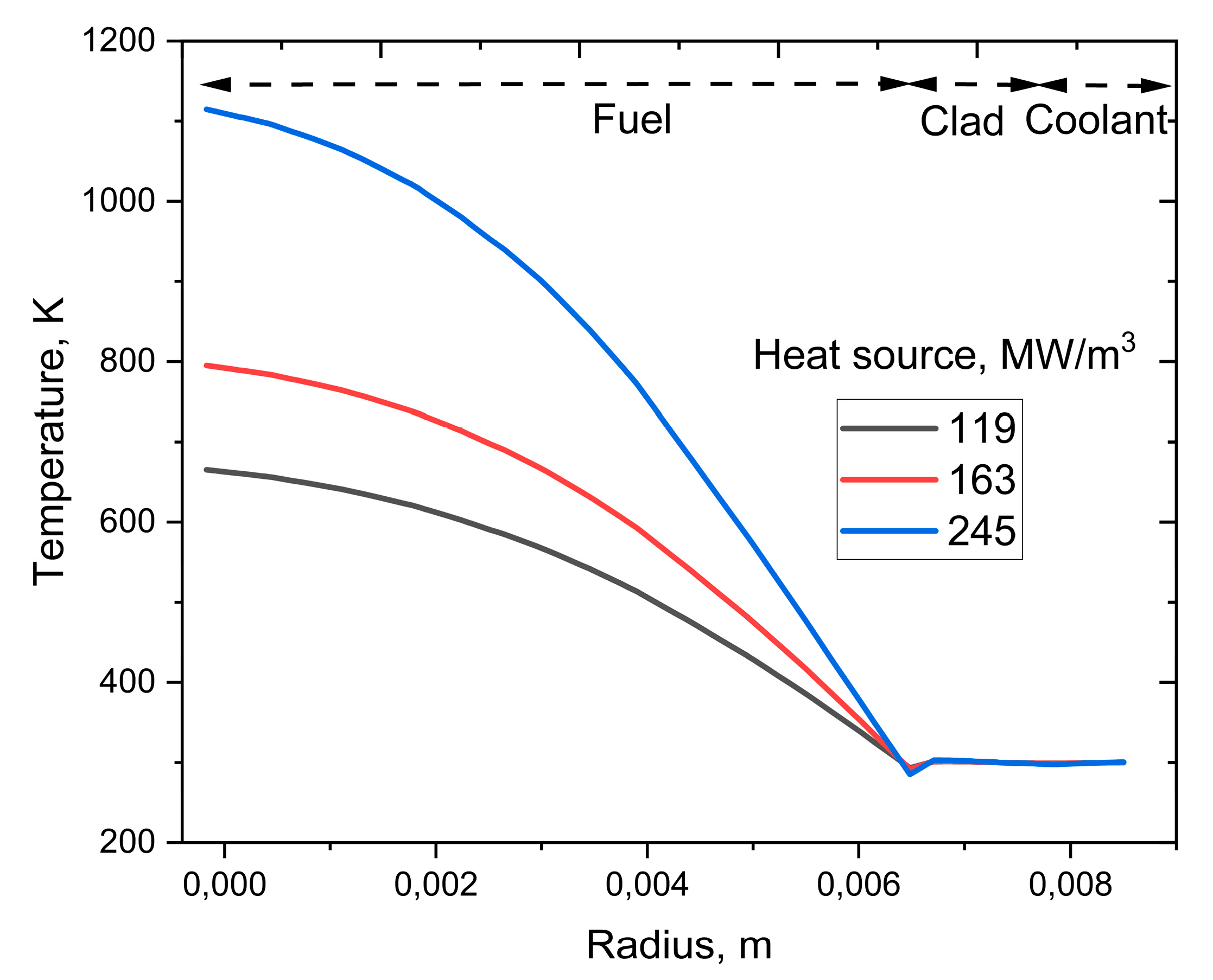
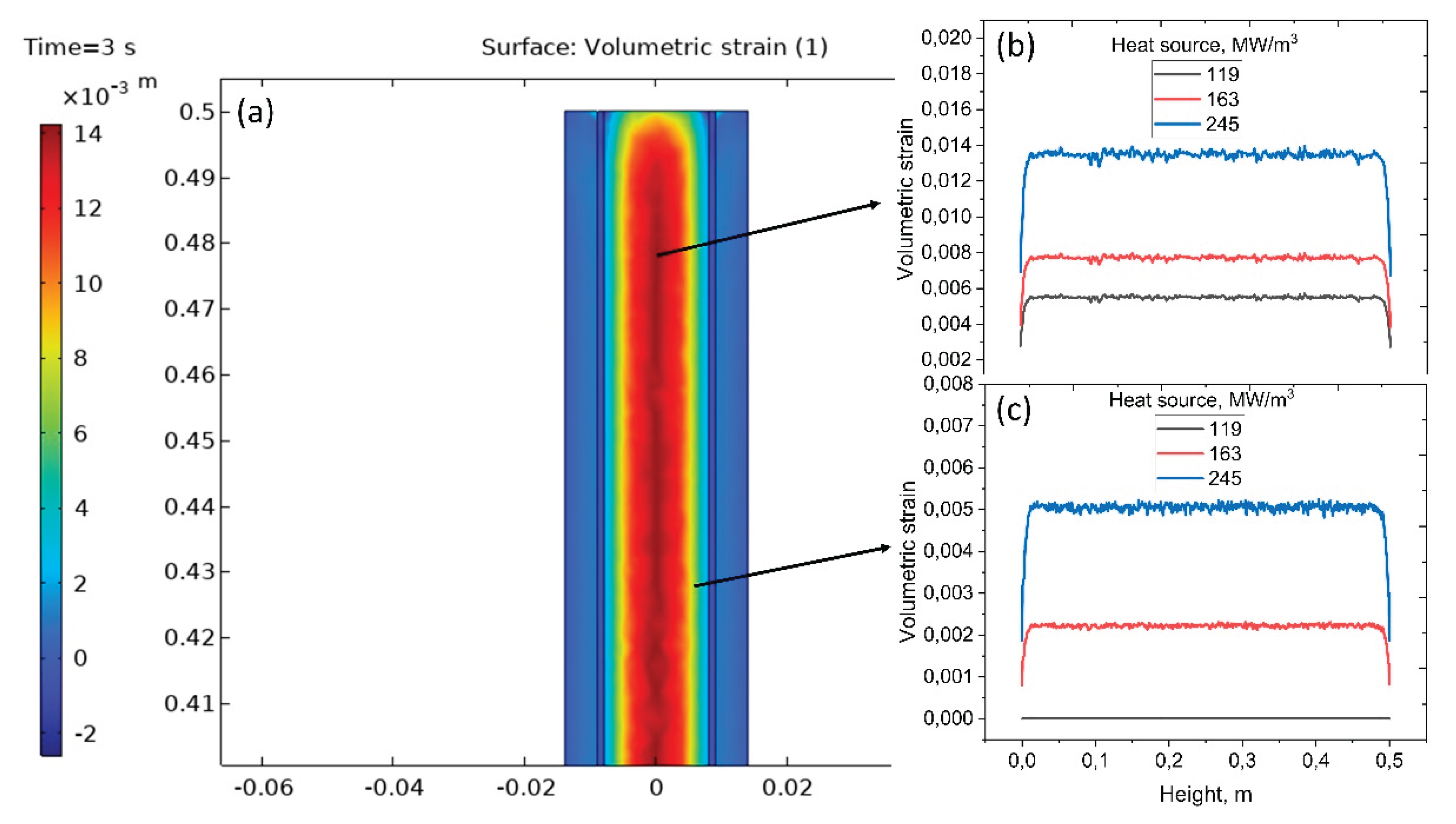
Figure 3 shows the maximum volumetric strain for the fuel material in axial direction. After 3 s of heating with volumetric source of 245 MW m⁻³, the 2-D strain map shows a characteristic high-strain core surrounded by a low-strain rim (Figure 3a). Axial line profiles (Figure 3b,c) taken through the pellet mid-radius and at the fuel–cladding interface confirm that the strain is remarkably uniform along the central ~ 0.5 m rod, reflecting the nearly homogeneous internal power distribution. Peak volumetric strain at the center rises from 0.006 to 0.014, respectively, increasing almost linearly with heat generation. Only near the pellet end faces does the strain decrease slightly, a result of end-face mechanical constraints and local heat-flux gradients. An increased volumetric strain in the fuel compared to the cladding material was also observed in the literature [31].
Figure 3.
Volumetric strain for the fuel after 3s of heating at three different heat sources. (a) 2D volumetric strain map, (b) strain at the center and (c) near the end.
Figure 3.
Volumetric strain for the fuel after 3s of heating at three different heat sources. (a) 2D volumetric strain map, (b) strain at the center and (c) near the end.
The two-dimensional map of total displacement shows minimal expansion in the central core (Figure 4a) where the cladding constrains radial motion, and maximum displacement along the outer surface where thermal expansion is less restricted. Profiles extracted across the diameter confirm that surface displacement increases systematically with the applied heat source—rising from ~0.004 mm at 119 MW m⁻³ to ~0.012 mm at 245 MW m⁻³—while the center remains comparatively immobile. Axial centerline profiles demonstrate nearly uniform elongation along the heated length, but with magnitudes that also scale with heat source, from ~0.015 mm to ~0.04 mm. The displacement profile suggests non-uniform deformation along the radial length, which is influenced by local thermal and mechanical loading distributions [32]. The displacement magnitudes remain within mechanical safety limits, providing critical input for assessing fuel-cladding mechanical interaction and ensuring structural integrity under elevated reactor-power conditions.
At t = 3 s the fuel rod exhibits an annular von Mises stress distribution with maxima at the outer surface and near-uniform stress along the active height (Figure 5a). Increasing volumetric heat generation from 119 to 245 MW m⁻³ raises centerline stress from ~0.6 to ~1.5 GPa (Figure 5b) and outer surface stress from ~0.4 to ~1.0 GPa (Figure 5c). These results confirm that differential thermal expansion between the hot core and cooler cladding drives the dominant mechanical loading. The stresses remain within structural safety margins but provide critical input for evaluating fuel–cladding mechanical interaction and long-term integrity of the reactor core under high-power operation.
Figure 6 shows thermo-mechanical simulation results of clad material, where higher internal heat generation (119 → 163 → 245 MW m⁻³) causes the cladding to expand almost uniformly along its 0.5 m length while remaining safely elastic. Axial displacement grows steadily from about 0.012 mm to 0.03 mm with increasing heat source, with only small end-effects. However, average strain stays close to zero (≈10⁻⁴), rising slightly with power and showing minor local oscillations, confirming gentle, homogeneous volumetric growth. Mean stress rises from roughly 0.15 GPa to 0.35–0.4 GPa, with small peaks near the ends, remaining well below the yield strength of typical zirconium alloys.
Changes in the velocity profile are evident in Figure 7a, over 3 s of operation, the coolant maintains a stable upward flow through the cladding channel. Surface velocities fall from ~1 m s⁻¹ at the inlet to ~0.85 m s⁻¹ mid-height, while centerline velocities decrease smoothly to ~0.75 m s⁻¹ at the outlet. Increasing the internal heat source from 119 to 245 MW m⁻³ produces only slight reductions in surface velocity and negligible changes along the centerline. However, no change in pressure is observed over the 3 s period, even with the increase in heat sources. These results confirm that the hydrodynamic field remains stable and well within design limits, ensuring reliable convective heat removal under the investigated power densities.
4. Conclusions
Thermo-mechanical and hydrodynamic simulations of a thorium-based fuel rod subjected to transient volumetric heating (119 → 245 MW m⁻³ over 3 s) reveal stable structural and coolant responses under elevated power densities. The fuel experiences a characteristic high-strain core surrounded by a low-strain rim, with centerline volumetric strain increasing nearly linearly from 0.006 to 0.014, while remaining axially uniform along the heated 0.5 m segment. Total displacement grows from ~0.004 mm to ~0.012 mm at the surface and from ~0.015 mm to ~0.04 mm along the axis, confirming that radial constraint by the cladding limits central motion. Mechanical loading is dominated by differential thermal expansion, producing annular von Mises stress fields that rise from 0.6 → 1.5 GPa at the center and 0.4 → 1.0 GPa at the surface, yet remain comfortably below zirconium-alloy yield strengths. The cladding itself expands almost uniformly, with axial displacement increasing from ~0.012 mm to ~0.03 mm, average strain near 10⁻⁴, and mean stress limited to 0.35–0.4 GPa, all well within elastic and design margins. Coolant hydrodynamics remain robust throughout the transient. Upward flow is stable, with only small velocity reductions (surface: 1.0 → 0.85 m s⁻¹, centerline: 0.75 m s⁻¹ at outlet). Collectively, these results confirm that the combined fuel–cladding system maintains mechanical integrity and coolant stability under rapid power ramps to at least 245 MW m⁻³, providing critical design data for next-generation heavy-water reactors employing thorium-based fuels.
Author Contributions
Conceptualization, K.B. and Z.I.; methodology, Y.U., Zh.A., A.A.; software, Y.S.; validation, K.B. and A.A.; formal analysis, K.B., A.H.; investigation, Y.S., Zh.A.; resources, Z.I., Zh.A., A.H.; data curation, Y.S., A.A.; writing—original draft preparation, K.B.; writing—review and editing, Z.I. A.H.; visualization, Y.S.; supervision, Z.I.; project administration, Z.I.; funding acquisition, Z.I. All authors have read and agreed to the published version of the manuscript.
Data Availability Statement
Data is contained within the article and available upon request.
Acknowledgments
This study was carried out as part of the implementation of the scientific program of the IRN BR24993225 for program-targeted financing of the Committee of Science of the Ministry of Science and Higher Education of the Republic of Kazakhstan for 2024-2026.
Conflicts of Interest
The authors declare no conflicts of interest.
References
- Che Zainul Bahri, C.N.A.; Ismail, A.F.; Ab Majid, A. Synthesis of thorium tetrafluoride (ThF₄) by ammonium hydrogen difluoride (NH₄HF₂). Nuclear Engineering and Technology 2019, 51, 792–799. [Google Scholar] [CrossRef]
- Rabir, M.H.; Ismail, A.F.; Yahya, M.S. Review of the micro-heterogeneous thoria–urania fuel for micro-sized high-temperature reactors. International Journal of Energy Research 2021, 45, 11440–11458. [Google Scholar] [CrossRef]
- Galahom, A.A.; Khaliil, A.S.; Alnassar, N.; Reda, S.M. Discussing the possibility of using thorium-based fuels as an alternative to uranium dioxide fuel for the APR-1400 reactor. Nuclear Engineering and Design 2024, 417, 112817. [Google Scholar] [CrossRef]
- Mohsen, M.Y.M.; Luhaib, S.A.; Alnassar, N.; Magzoub, O.A.; Abdel-Rahman, M.A.E.; Sallah, M.; Galahom, A.A. Investigating the possible advantages of using different concentrations of transuranic elements with thorium–uranium dioxide as a fuel for PBMR-400. Progress in Nuclear Energy 2025, 178, 105512. [Google Scholar] [CrossRef]
- Ibrahim, A.; Aziz, M.; El-Kameesy, S.U.; El-Fiki, S.A.; Galahom, A.A. Analysis of thorium fuel feasibility in a large-scale gas-cooled fast reactor using MCNPX code. Annals of Nuclear Energy 2018, 111, 460–467. [Google Scholar] [CrossRef]
- Chaudri, K.S.; Tian, W.; Su, G.; Qiu, S. Coupled neutronics/thermal-hydraulics evaluation for thorium-based fuels in thermal-spectrum SCWR. Progress in Nuclear Energy 2013, 68, 55–68. [Google Scholar] [CrossRef]
- Kamarudin, N.A.Z.; Ismail, A.F.; Rabir, M.H.; Siong, K.K. Neutronic optimization of thorium-based fuel configurations for minimizing slightly used nuclear fuel and radiotoxicity in small modular reactors. Nuclear Engineering and Technology 2024, 56, 2641–2649. [Google Scholar] [CrossRef]
- Amatullah, A.; Permana, S.; Irwanto, D.; Aimon, A.H. Comparative analysis on small modular reactor (SMR) with uranium and thorium fuel cycles. Nuclear Engineering and Design 2024, 418, 112934. [Google Scholar] [CrossRef]
- Alnassar, N.; Al-Aqeel, M.A.; Alanazi, S.; Algarawi, M.; Mohsen, M.Y.M.; Galahom, A.A. Exploring the potential advantages of replacing UO₂ with different thorium-based fuels in U.S. SCLWR. Nuclear Engineering and Design 2025, 432, 113751. [Google Scholar] [CrossRef]
- Galahom, A.A.; Sharaf, I.M. Finding a suitable fuel type for disposal of accumulated minor actinides in spent nuclear fuel in PWRs. Progress in Nuclear Energy 2021, 136, 103749. [Google Scholar] [CrossRef]
- Parker, S.S.; Newman, S.; Fallgren, A.J. Neutronic performance of a compact 10 MWe nuclear reactor with low-enrichment (ThₓU₁₋ₓ)N fuel. JOM 2021, 73, 3576–3587. [Google Scholar] [CrossRef]
- Zheng, G.; Wu, H.; Wang, J.; Chen, S.; Zhang, Y. Thorium-based molten-salt SMR as the nuclear-technology pathway from a market-oriented perspective. Annals of Nuclear Energy 2018, 116, 177–186. [Google Scholar] [CrossRef]
- Aufiero, M.; Cammi, A.; Fiorina, C.; Luzzi, L.; Sartori, A. A multi-physics time-dependent model for the lead fast reactor single-channel analysis. Nuclear Engineering and Design 2013, 256, 14–27. [Google Scholar] [CrossRef]
- Aldebie, F.; Fernandez-Cosials, K.; Hassan, Y.A. Thermal–mechanical safety analysis of a heat-pipe micro reactor. Nuclear Engineering and Design 2024, 420, 113003. [Google Scholar] [CrossRef]
- Jiao, G.; Xia, G.; Zhu, H.; Zhou, T.; Peng, M. Thermal-mechanical coupling characteristics and heat pipe failure analysis of heat pipe cooled space reactor. Ann. Nucl. Energy 2023, 192, 110025. [Google Scholar] [CrossRef]
- Jiao, G.; Xia, G.; Wang, J.; Peng, M. Thermal-hydraulic and load-following performance analysis of a heat pipe cooled reactor. Nucl. Eng. Technol. 2024, 56, 1698–1711. [Google Scholar] [CrossRef]
- Cammi, A.; Luzzi, L.; Ricotti, M.E.; Tarantino, M. Coupled multiphysics analysis of a liquid-fuel fast reactor. Progress in Nuclear Energy 2011, 53, 771–779. [Google Scholar] [CrossRef]
- Daher, D.H.; Kotb, M.; Khalaf, A.M.; El-Koliel, M.S.; Soliman, A.Y. Simulation of a molten salt fast reactor using the COMSOL Multiphysics software. Nucl. Sci. Tech. 2020, 31, 115. [Google Scholar] [CrossRef]
- Kim, Y.S.; Lee, B.C.; Kim, H.R.; Lee, J.C. Diametral Creep Prediction of the Pressure Tubes in CANDU Reactors. Nucl. Eng. Technol. 2011, 43, 517–526. [Google Scholar] [CrossRef]
- Park, J.H.; Kim, H.R.; Lee, B.C. Critical Power Ratio with New Pressure Tube Creep Data of a CANDU-6. In Proceedings of the Korean Nuclear Society Spring Meeting, Jeju, Korea, 23–24 May 2019. [Google Scholar]
- Kim, Y.S.; Kim, Y.S.; Jung, H.Y.; Lee, J.C.; Kim, H.R. High-Temperature Creep Deformation Evaluation in CANDU Pressure Tubes. Int. J. Press. Vessels Pip. 2021, 195, 104566. [Google Scholar]
- Soliman, M.; Yassin, Y. Thermal-Hydraulic Analysis of the Thorium-Based Advanced CANDU Reactor (TACR-1300) Fuel Channel. Ann. Nucl. Energy 2019, 133, 248–259. [Google Scholar]
- Galahom, A.A.; Ibrahim, A. Integrated analysis to investigate the viability of using thorium-based fuel instead of traditional fuel in CANDU reactor. Nucl. Eng. Des. 2022, 398, 111969. [Google Scholar] [CrossRef]
- Mohsen, M.Y.M.; Abdel-Rahman, M.A.E.; Galahom, A.A. Ensuring the Possibility of Using Thorium as a Fuel in a Pressurized Water Reactor (PWR). Nuclear Science and Techniques 2021, 32, 137. [Google Scholar] [CrossRef]
- Hammer, R.R. Zircaloy-4, Uranium Dioxide, and Materials Formed by Their Interaction: A Literature Review with Extrapolation of Physical Properties to High Temperatures; Idaho Nuclear Corp.: Idaho Falls, USA, January 1, 1967. Report No. IN-1093. U.S. Atomic Energy Commission, DOE NSTI Report 4136888.
- Shields, A.E.; Hernandez, S.E.R.; de Leeuw, N.H. Theoretical Analysis of Uranium-Doped Thorium Dioxide: Introduction of a Thoria Force Field with Explicit Polarization. AIP Adv. 2015, 5, 087118. [Google Scholar] [CrossRef]
- Takeuchi, T.; Kakubo, Y.; Matsukawa, Y.; Nozawa, Y.; Toyama, T.; Nagai, Y.; Nishiyama, Y.; Katsuyama, J.; Yamaguchi, Y.; Onizawa, K. Effects of neutron irradiation on microstructures and hardness of stainless steel weld-overlay cladding of nuclear reactor pressure vessels. J. Nucl. Mater. 2014, 449, 273–276. [Google Scholar] [CrossRef]
- Kurbanova, B.; Aimaganbetov, K.; Ospanov, K.; Abdrakhmanov, K.; Zhakiyev, N.; Rakhadilov, B.; Sagdoldina, Z.; Almas, N. Effects of Electron Beam Irradiation on Mechanical and Tribological Properties of PEEK. Polymers 2023, 15, 1340. [Google Scholar] [CrossRef]
- Almas, N.; Kurbanova, B.; Zhakiyev, N.; Rakhadilov, B.; Sagdoldina, Z.; Andybayeva, G.; Serik, N.; Alsar, Z.; Utegulov, Z.; Insepov, Z. Mechano-Chemical Properties of Electron Beam Irradiated Polyetheretherketone. Polymers 2022, 14, 3067. [Google Scholar] [CrossRef]
- Chaudri, K.S.; Tian, W.; Su, G.; Qiu, S. Coupled neutronics/thermal-hydraulics evaluation for thorium-based fuels in thermal-spectrum SCWR. Prog. Nucl. Energy 2013, 68, 55–64. [Google Scholar] [CrossRef]
- Mohsen, M.Y.M.; Soliman, A.Y.; Abdel-Rahman, M.A.E. Thermal-hydraulic and solid mechanics safety analysis for VVER-1000 reactor using analytical and CFD approaches. Prog. Nucl. Energy 2020, 130, 103568. [Google Scholar] [CrossRef]
- Mohsen, M. Y. M.; Abdel-Rahman, M. A. E.; Hassan, M. S.; Galahom, A. A. G. Searching for the Most Optimum Burnable Absorbers (BAs) for AP-1000 from the Neutronic, Thermal-Hydraulic, and Solid Mechanics Points of View. Nuclear Eng. Des. 2022, 391, 111728. [Google Scholar] [CrossRef]
Figure 1.
Vertical and horizontal cross-sections of CANDU-6 bundle and fuel pin(taken from [23]).
Figure 1.
Vertical and horizontal cross-sections of CANDU-6 bundle and fuel pin(taken from [23]).
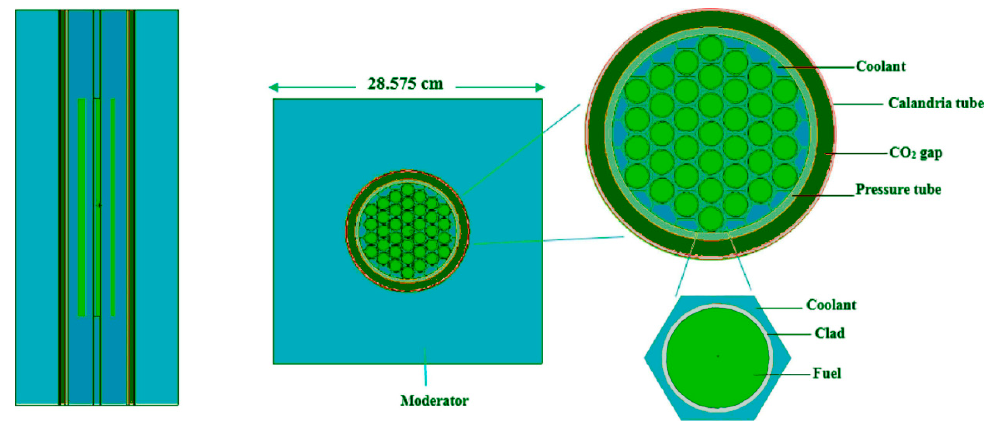
Figure 2.
Pin power distribution (in kW) through fuel bundle(taken from [23]).
Figure 2.
Pin power distribution (in kW) through fuel bundle(taken from [23]).
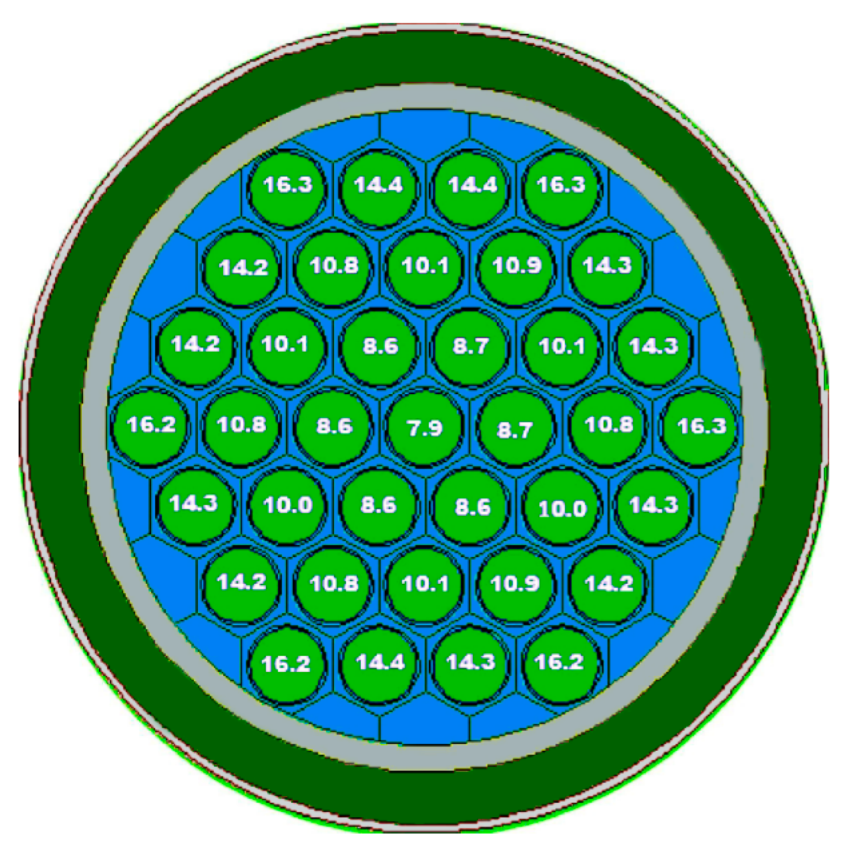
Figure 3.
Mesh of the fuel rod (a) top and (b) cross views.
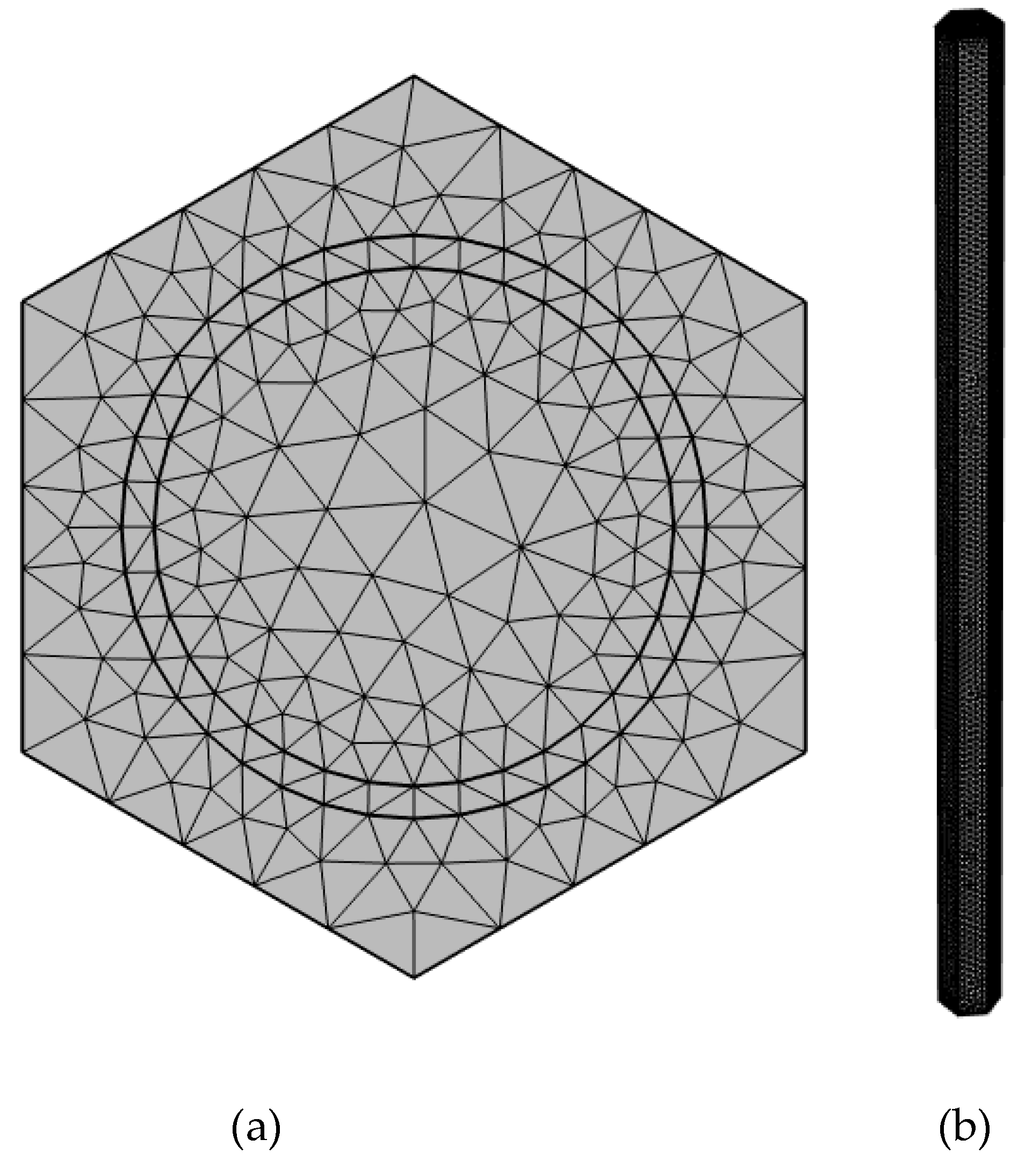
Figure 4.
Displacement magnitude for the fuel after 3s of heating at three different heat sources. (a) 2D displacement map, (b) displacement magnitude at the center and (c) near the end of the fuel rod.
Figure 4.
Displacement magnitude for the fuel after 3s of heating at three different heat sources. (a) 2D displacement map, (b) displacement magnitude at the center and (c) near the end of the fuel rod.
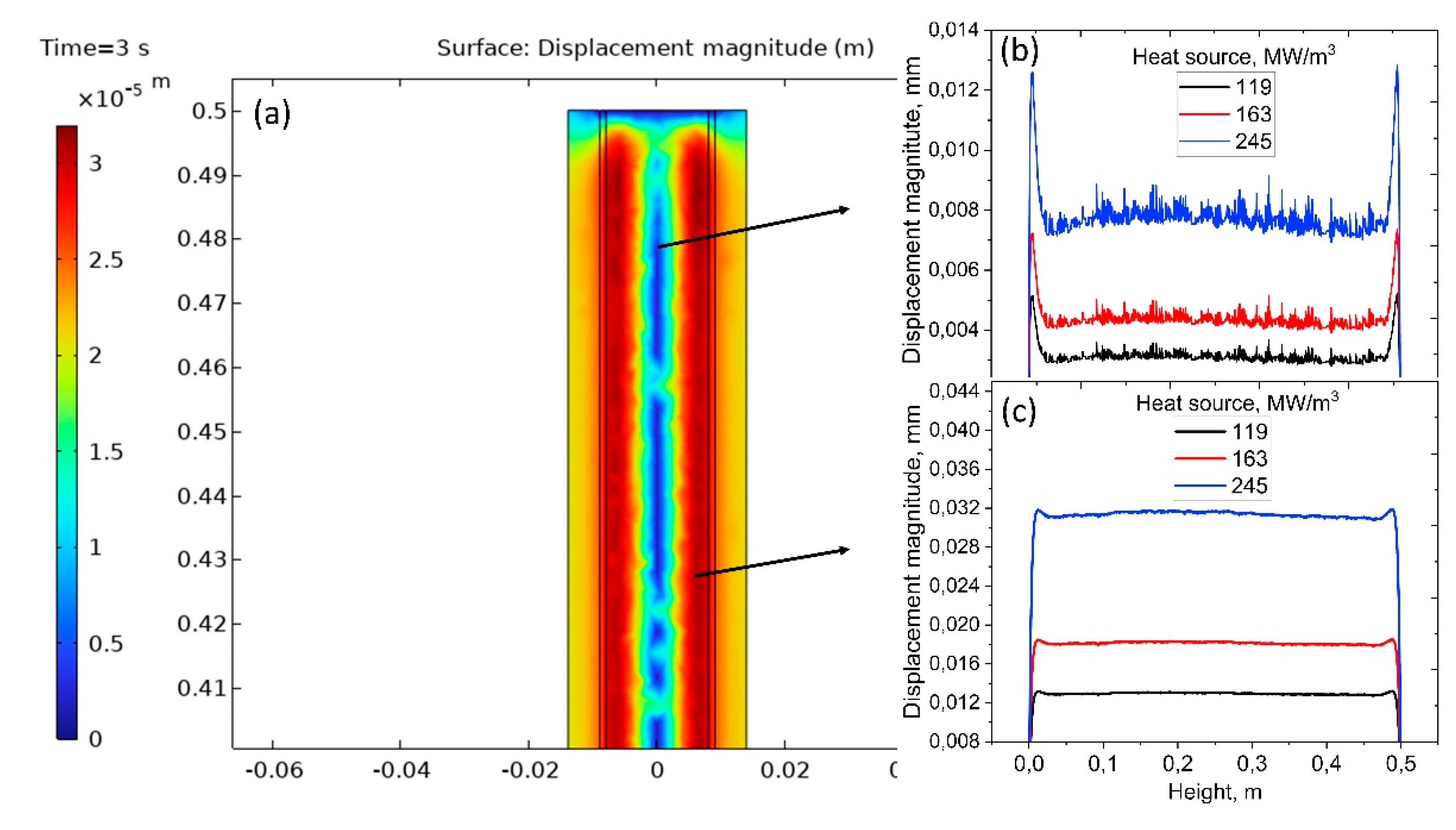
Figure 5.
von Mises stress results for the fuel after 3s of heating at three different heat sources. (a) 2D von Mises stress map, (b) stress at the center and (c) near the end of the fuel rod.
Figure 5.
von Mises stress results for the fuel after 3s of heating at three different heat sources. (a) 2D von Mises stress map, (b) stress at the center and (c) near the end of the fuel rod.
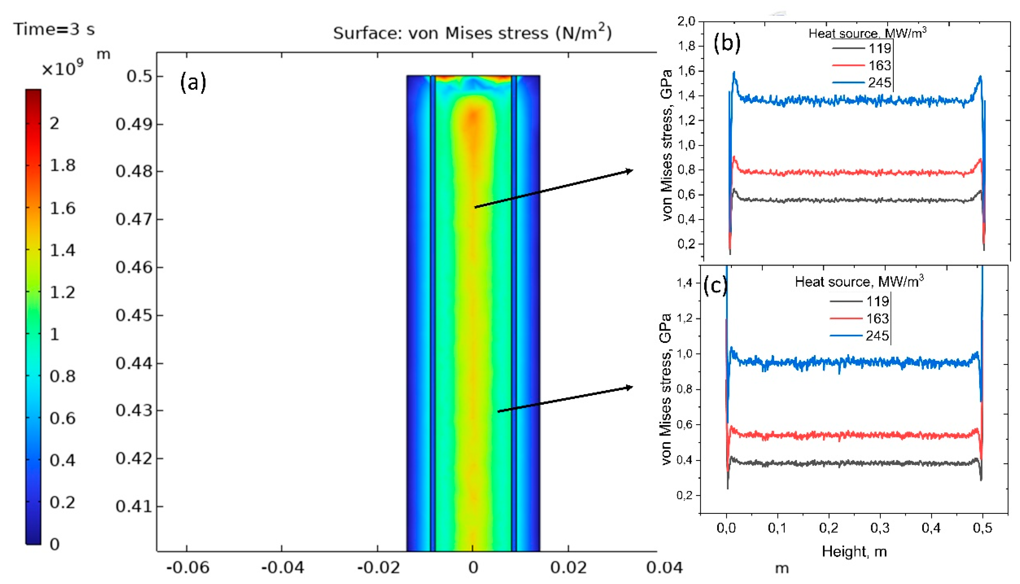
Figure 6.
Thermo-mechanical simulation results of clad material. (a) Displacement magnitude, (b) Volumteric strain and (c) von Mises stress results.
Figure 6.
Thermo-mechanical simulation results of clad material. (a) Displacement magnitude, (b) Volumteric strain and (c) von Mises stress results.
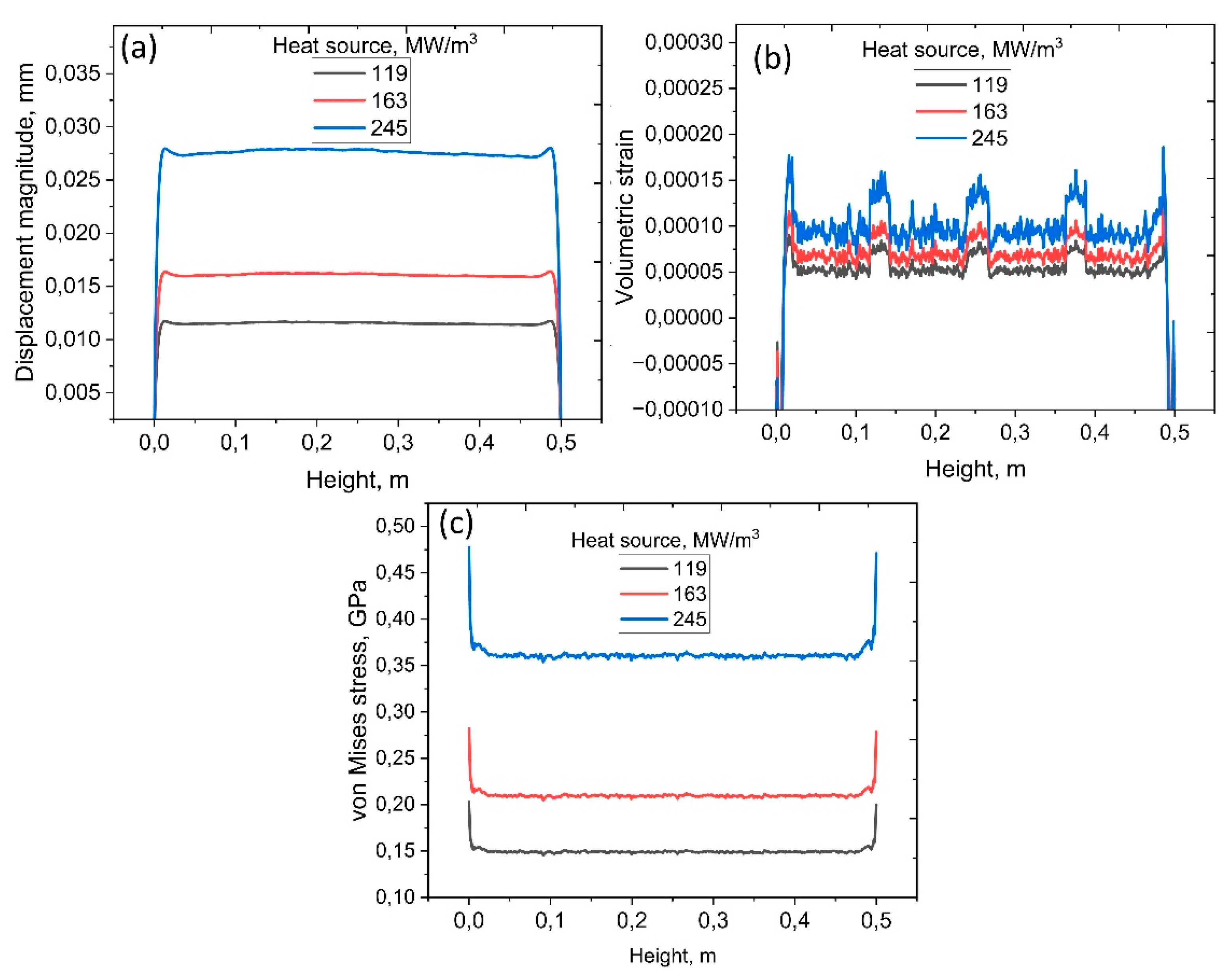
Figure 7.
Velocity profile(a) change after 3s heat exposure, (b) stress at the center and (c) near the end of the fuel rod.
Figure 7.
Velocity profile(a) change after 3s heat exposure, (b) stress at the center and (c) near the end of the fuel rod.
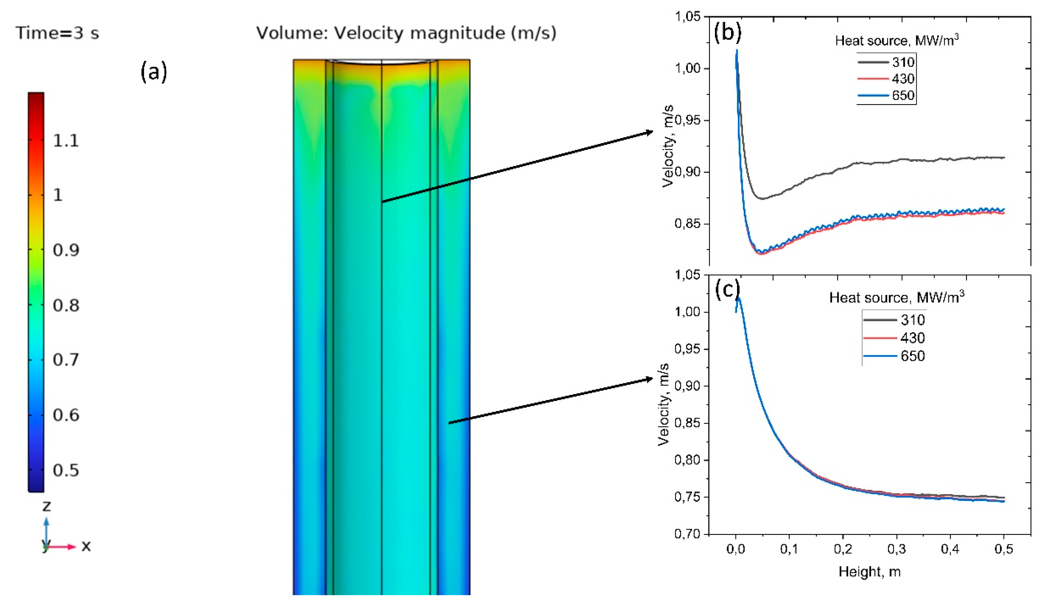

Table 1.
The design parameters and dimensions of reactor core.
| Parameter | Value |
|---|---|
| Fuel channel lattice geometry | Square |
| Fuel channel pitch | 28.575 cm |
| Pressure tube material | Zr 2.5Nb |
| Pressure tube thickness | 0.4343 cm |
| Calandria tube material | Zircalloy-2 |
| Calandria tube thickness | 0.1397 cm |
| Fuel material | (Th, 233U)O2 |
| Cladding material | zircalloy-4 |
| Cladding thickness | 0.04 cm |
| Number of fuel elements per bundle | 37 pin |
| Fuel pin lattice geometry | Hexagonal |
| Fuel pin pitch | 1.4885 cm |
| Fuel element height | 49.53 cm |
| Moderator material | D2O |
| Coolant material | D2O |
Table 2.
Converted radial-power values to heat source for the maximum, median, and minimum power levels.
Table 2.
Converted radial-power values to heat source for the maximum, median, and minimum power levels.
| Radial power, kW | Heat source, MW/m3 |
|---|---|
| 16.3 | 245 |
| 10.8 | 163 |
| 7.9 | 119 |
Disclaimer/Publisher’s Note: The statements, opinions and data contained in all publications are solely those of the individual author(s) and contributor(s) and not of MDPI and/or the editor(s). MDPI and/or the editor(s) disclaim responsibility for any injury to people or property resulting from any ideas, methods, instructions or products referred to in the content. |
© 2025 by the authors. Licensee MDPI, Basel, Switzerland. This article is an open access article distributed under the terms and conditions of the Creative Commons Attribution (CC BY) license (http://creativecommons.org/licenses/by/4.0/).
Copyright: This open access article is published under a Creative Commons CC BY 4.0 license, which permit the free download, distribution, and reuse, provided that the author and preprint are cited in any reuse.


