
Submitted:
24 September 2025
Posted:
24 September 2025
You are already at the latest version
Abstract
Advances in transportation and mobility constitute a cornerstone of sustainable development. This work presents the SNAP vehicle, a four-wheel, pedal-assisted electric platform designed to bridge the gap between bicycles and conventional automobiles. Particular attention is devoted to the drivetrain architecture and to the adoption of a drive-by-wire system in place of a traditional chain transmission. The study specifically examines the single-motor configuration, in which traction is provided by the rear-right wheel, and includes the instrumentation of a prototype vehicle to assess whether such a layout ensures satisfactory dynamic performance. These investigations directly contribute to two United Nations Sustainable Development Goals: SDG7, which promotes affordable and clean energy, and SDG11, which focuses on creating sustainable cities and communities.
Keywords:
SDG7
; SDG11
; electric-assisted vehicles
; quadricycle
; mobility
; last-mile delivery
; dynamic modeling
1. Introduction
One of the main objectives of scientific research in the automotive sector is the reduction of CO₂ emissions, which has driven a radical transformation of propulsion architectures in recent decades. Today’s electrified mobility is dominated by high- and mid-power vehicles designed to provide adequate performance in diverse driving conditions but inevitably characterized by bulky and costly battery packs, whose production and disposal generate considerable environmental impacts. For instance, the production of a 45-kWh battery, typical for a mid-power electric vehicle, releases as much CO₂ as an internal combustion car driving for 40,000 km [1,2]. Moreover, the large mass of these vehicles results in high energy consumption, particularly in urban contexts, where electricity is still primarily produced from fossil fuels. Since the transition to renewable energy will take several decades, the most effective short-term strategy to mitigate emissions lies in drastically lowering the energy requirements of electric vehicles. In this respect, urban mobility calls for lightweight, low-power solutions capable of ensuring safety, comfort, and accessibility, where energy consumption is directly correlated to vehicle mass. Electric L-category Vehicles (ELVs) and cargo bikes compliant with EN15194 emerge as promising alternatives, especially since they are compact, low-cost, and allowed in restricted traffic areas [3].
Several innovative pedal-assisted cargo vehicles have been introduced in recent years (see Figure 1), aiming to optimize urban logistics and sustainable mobility [4]. Although they differ in structural layout, load capacity, and propulsion solutions, they all fall within the pedelec (EPAC) regulatory framework, thereby combining the circulation advantages of bicycles with performance closer to that of light quadricycles.
The Citkar Loadster [5] represents a hybrid concept between a pedelec and a light commercial micro-vehicle, with a modular steel frame and composite bodywork, independent front suspension, and a 250 W motor delivering up to 70 Nm torque. With a payload capacity of about 300 kg and a load volume up to 1.5 m³, it provides significant cargo potential while maintaining compliance with pedelec speed limits (25 km/h).
The EAV (Electric Assisted Vehicle) [6] is conceived as a modular logistics platform, available in pedelec versions or as a light quadricycle (L6e). It features a composite monocoque frame with semi-closed cabin, interchangeable cargo modules ranging from 1–2 m³, and flexible battery capacities between 2–4 kWh. Depending on the configuration, autonomy varies from 30–60 km, while payload reaches 200 kg. Some versions allow higher assisted speeds up to 45 km/h under quadricycle homologation.
The CityQ [7] distinguishes itself through a fully electronic pedal-by-wire drivetrain, eliminating the mechanical chain and enabling advanced integration of electronic assistance. Its lightweight aluminum frame supports a closed cabin with passenger or cargo adaptability, while the modular lithium-ion battery (1.4–2 kWh) provides ranges of 70–100 km. With a payload of 150–200 kg and options for transporting either passengers or goods, the CityQ bridges personal mobility and urban micrologistics.
The Armadillo Velove [8], developed in Sweden, adopts a container-swap system with standardized cargo boxes (1.5–2.0 m³), enabling seamless integration into urban micro-hub logistics. Its tubular steel or aluminum chassis, independent suspension on all wheels, and 250 W pedal-assist motor make it particularly suited for urban freight distribution. The vehicle supports payloads of up to 200 kg, with an autonomy of 40–60 km, and emphasizes operational efficiency through rapid container replacement.
The Vok S [9], from Estonia, combines the agility of a bicycle with the stability of a quadricycle and the loading capacity of a micro-van. Built on a lightweight tubular steel/aluminum frame with a partially enclosed cabin, it offers a cargo capacity of 2.0 m³ and payloads up to 200 kg. Its modular design allows for quick box swapping, while the 250 W pedal-assist motor, paired with 1.5–2.5 kWh batteries, ensures ranges between 40–80 km under varying urban loads.
Finally, the Mubea Urban [10] constitutes a modular cargo quadricycle designed for last-mile distribution. With a robust tubular monocoque, interchangeable cargo units up to 2.0 m³, and payload capacity of 250 kg, it prioritizes versatility and integration into smart logistics networks. Its battery system ranges from 2–4 kWh, providing 60–100 km of autonomy, while hydraulic disc brakes and independent suspension systems ensure safety and durability in urban operation.
All the examined vehicles share compliance with pedelec standards (250 W, 25 km/h), but they diverge in terms of modularity, payload, and autonomy. Collectively, these vehicles demonstrate the technological diversity of emerging cargo pedelecs, highlighting a trend toward modularity, operational efficiency, and integration into sustainable urban freight systems.
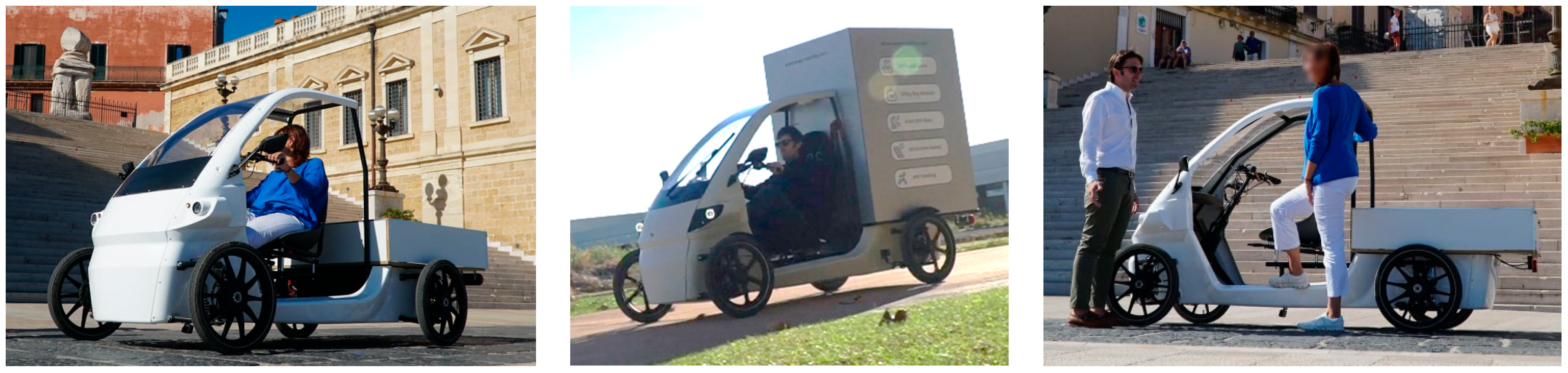
In this context, the present research systematically addresses the study, development and testing of a new type of pedal-assisted electric lightweight vehicle, classified as an ELV and compliant with EN15194 and DIN79010 standards. The SNAP quadricycle, shown in Figure 2, combines the low energy consumption of micro-mobility solutions with higher levels of safety, comfort, and protection against adverse weather conditions. SNAP features a closed cockpit, a curb weight of about 130 kg, a payload capacity of 160 kg, and is powered by two 980 Wh batteries, ensuring a range of 60 km extendable to 120 km through battery swap. The SNAP vehicle distinguishes itself from competitors by combining an advanced automotive-inspired suspension geometry that complies with Ackermann steering principles, full splash protection including the underside, a feature rarely found in similar solutions, a drive-by-wire system, and seatbelt integration. Taken together, these unique characteristics make the vehicle a one-of-a-kind design in its category.
One key feature of SNAP is the adoption of drive-by-wire architecture that replaces original traditional mechanical transmission (chain, sprockets, differential, gearbox and semiaxes), whose concept and analysis was previously presented by the authors [11,12]. Although its maturity and reliability, the mechanical drivetrain proved relatively complex to build and maintain due to the presence of numerous moving parts. In this paper, a second generation of drivetrain is introduced based on a drive-by-wire solution. It drastically simplifies the architecture by eliminating chains and gears, thus improving modularity, reducing overall weight, and minimizing maintenance requirements. The drive-by-wire drivetrain is implemented through a single right rear in-wheel motor. This design choice significantly reduces overall weight and mechanical complexity, and at the same time, it lowers production costs by avoiding the need for dual-motor synchronization and additional components. A specific concern regarding the potential occurrence of a side-slip angle due to asymmetric torque distribution in the single in-wheel motor is investigated through a dynamic model and experimental measurements. Results have confirmed that the phenomenon was negligible, with differences limited to a +2% rotational speed of the driven wheel, attributable to tire slip under torque delivery.
The evidence collected suggests that while both drivetrain solutions are technically viable for urban ELVs, the drive-by-wire solution emerges as the most promising for future development, thanks to its versatility, efficiency, and adaptability to modular configurations. In conclusion, the research demonstrates that adopting innovative drivetrain architectures in lightweight electric vehicles can significantly advance sustainable urban mobility, fostering safer, more livable, and low-emission cities, while establishing a solid foundation for new design paradigms in the sector.
The paper is structured as follows: in Section 2, the drive-by-wire architecture is introduced and motivated in terms of mechanical simplification and reduced maintenance, alongside a comparative discussion of efficiency relative to chain-based transmissions. A simplified analytical model of the SNAP vehicle configured with a single right-rear in-wheel motor is developed to quantify efficiency and assess potential destabilizing yaw moment.
In Section 3, the custom instrumentation is detailed, enabling measurement of wheel speeds, steering angle, and tri-axial accelerations, together with integration and calibration procedures. A straight-line experiment is then conducted to evaluate whether the single, off-center rear motor introduces a yaw moment, with data processing metrics and decision criteria defined to detect any such bias.
2. Drive by Wire System
Following the limitations observed in the previous conventional mechanical transmission system, shown in [11], such as the high number of moving parts, the complexity of chain alignments, and the costly maintenance requirements, a structural redesign of the SNAP powertrain was undertaken [13,14,15,16]. This led to the development of a second-generation configuration based on drive-by-wire technology. The revised architecture replaces the mid-drive solution with an external-rotor in-wheel electric motor, positioned within the hub of the right rear wheel only. This propulsion system, fully independent of the mechanical drivetrain, employs an electronically controlled direct-drive mechanism, as shown in Figure 4 thereby eliminating the need for chains, gearboxes, and differentials. The result is a substantially simplified vehicle layout with reduced mechanical wear.
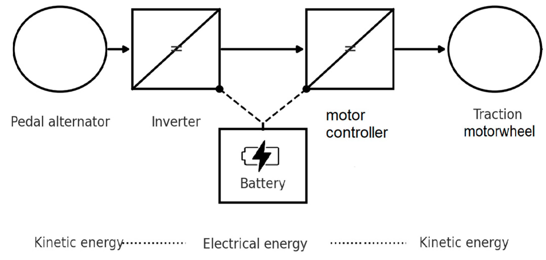
At the core of this solution lies the drive-by-wire system, which transforms pedalling into electrical energy through a generator located in place of the bottom bracket. The generated energy is transmitted via cable to the electric motor, where it is reconverted into mechanical energy for vehicle propulsion. Furthermore, the system allows for adjustable pedalling resistance according to the selected effort level, ensuring nearly constant torque and cadence at the pedals.
Beyond enhancing maintainability, this configuration introduces new design opportunities, particularly for cargo vehicles intended for last-mile delivery, where traditional drivetrains impose structural constraints such as the chain tunnel. The new layout enables a lower loading platform, improving both stability and design flexibility.
Although the use of a single motor on only one rear wheel results in a lateral shift of the vehicle’s center of gravity, it nonetheless reduces costs and control system complexity compared to a dual-motor solution with two 125 W units, which would require sophisticated synchronization and additional mechanical and electronic components.
The drive-by-wire architecture operates as an electric transmission system, in which the mechanical energy generated by pedalling is entirely converted into electrical energy, without any mechanical linkage between the crank set and the driving wheel. The mechanical power provided by the user is transduced into electrical energy through a generator integrated within the bottom bracket, which is electrically coupled to a direct-drive motor installed in the right rear wheel.
This configuration enables a complete decoupling between pedalling kinematics and electric traction, allowing independent control of both the torque applied to the driving wheel and the pedalling cadence. The electronic transmission is managed by a centralized control unit that regulates, in real time, the energy flow among the generator, the motor, and the storage system (battery), while optimizing operating points according to efficiency, load, and topographical conditions.
Figure 3.
The first generation of chain-based drivetrain.
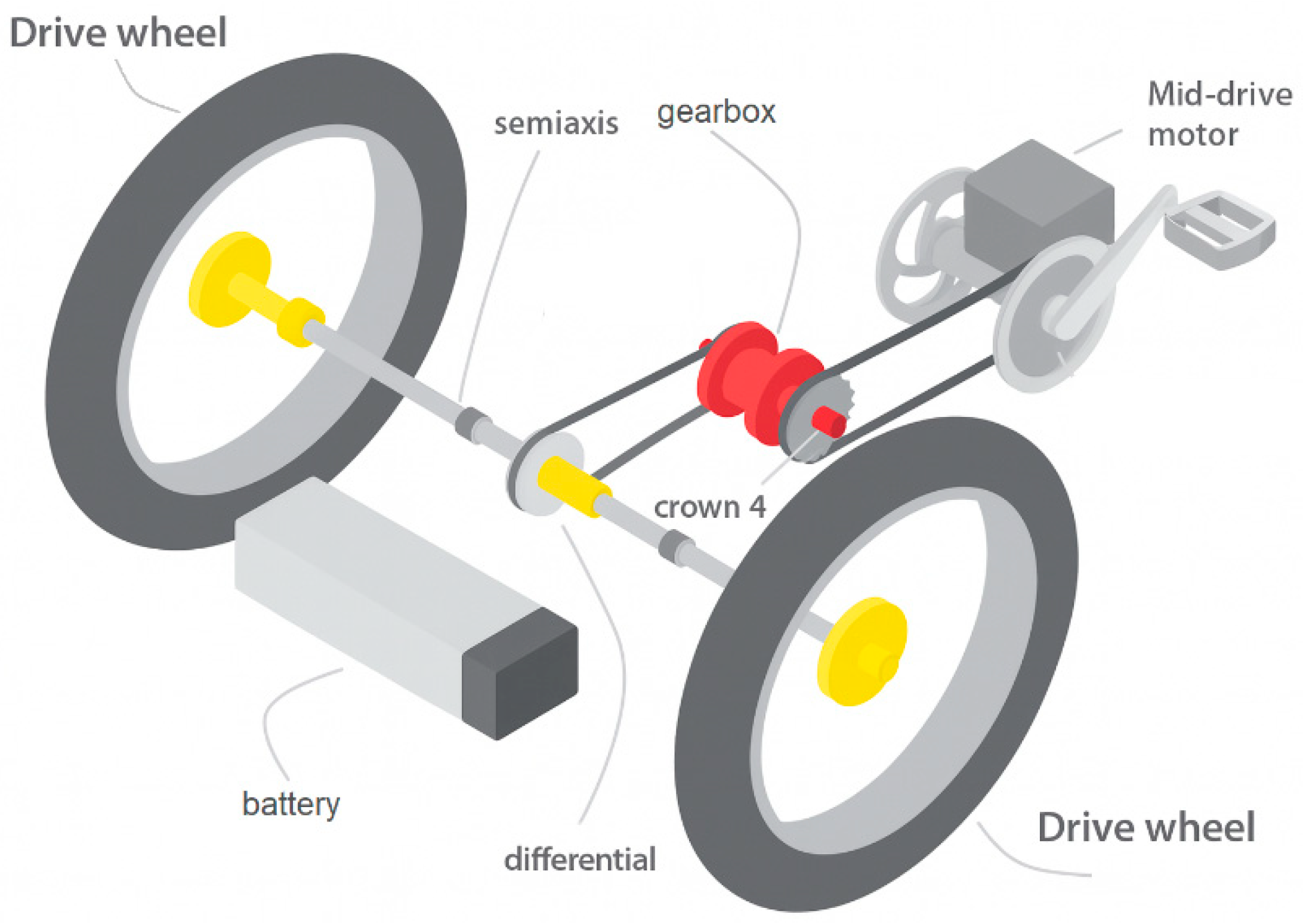
Figure 4.
Schematic of the drive-by-wire system.
In the context of the SNAP vehicle, this configuration enables a more flexible design of the four-wheel chassis, while simultaneously improving energy management efficiency and mass distribution. The absence of a mechanical transmission further reduces friction and energy losses typically associated with chains, whereas the electrical coupling between the energy source (pedalling) and the actuator (motor) allows for the implementation of advanced control strategies, including active regeneration and real-time adaptation of the traction response to operating conditions.
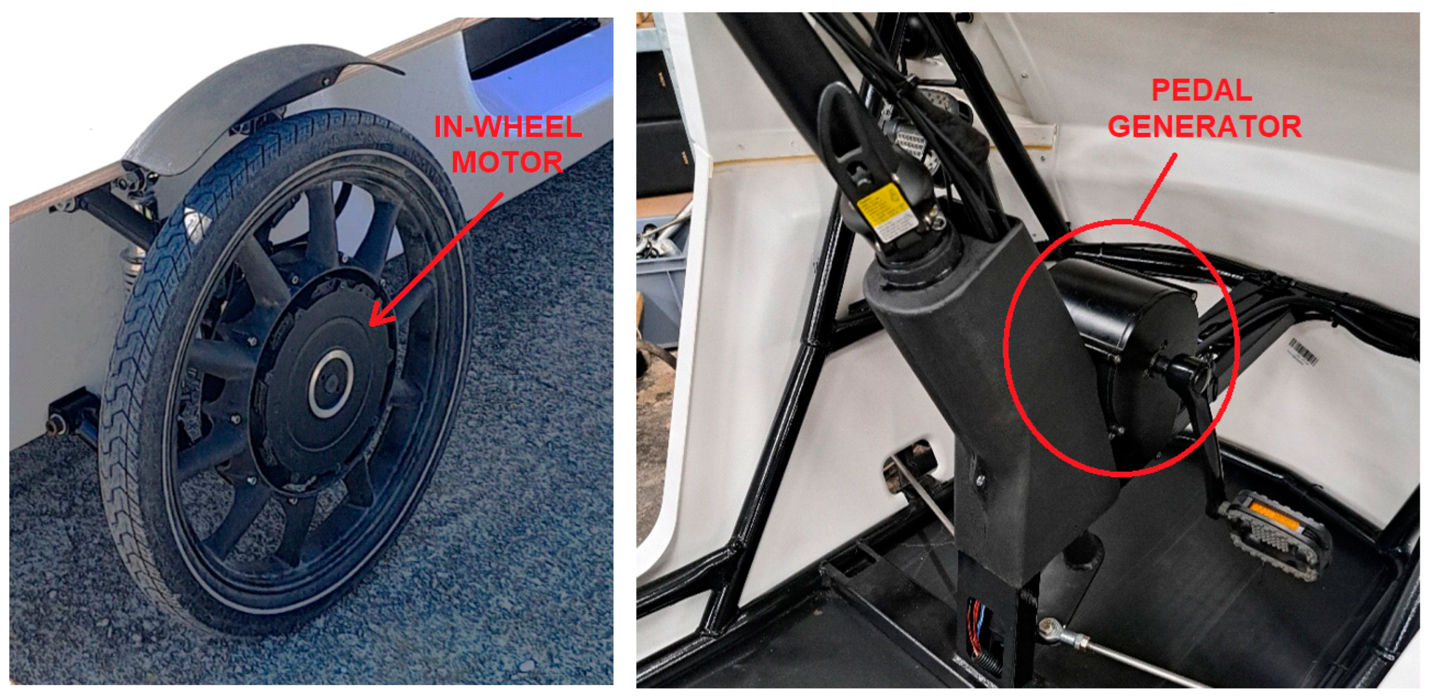
Figure 5.
The SNAP vehicle with drive-by-wire drivetrain. On the left the in-wheel motor, on the right the pedal generator.
Figure 5.
The SNAP vehicle with drive-by-wire drivetrain. On the left the in-wheel motor, on the right the pedal generator.
Additionally, the drive-by-wire architecture provides the benefit of regenerative braking. The system produce during urban cycles a charging current comparable to that delivered by the external electrical supply, i.e., around 5 A at 48 V. Considering that the drivetrain delivers a continuous output power of 250 W under normal operating conditions, the regenerative phase can generate up to 240 W (5 A × 48 V). This value is nearly equivalent to the average output power of the motor itself, suggesting that regenerative braking can play a substantial role in improving effective system efficiency.
These aspects acquire further importance considering the effect of ambient and tire temperatures on driving resistance, which has been shown to significantly increase energy consumption under cold conditions [17]. However, such phenomena are not addressed in the present study, as they are currently the subject of ongoing experimental investigations to be reported in future works.
The next step is to investigate the dynamic behavior of the drive-by-wire configuration. In particular, the potential implications of employing a single in-wheel motor on the right rear wheel must be assessed, especially with regard to possible asymmetries in vehicle handling and stability.
3. Dynamic Modeling
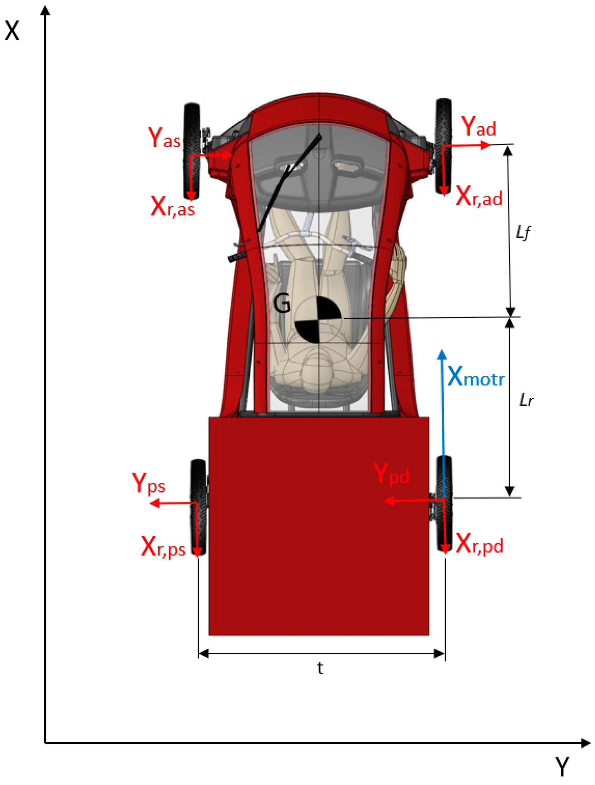
A mathematical lateral dynamic model under straight-line driving conditions is developed to describe the behaviour of the single in-wheel motor configuration, with the aim of estimating the slip angle induced by the eccentricity of the driving force acting on the right rear tire.
Figure 6.
The dynamic model schematic.
where:
Yad = lateral force front-right wheel
Yas = lateral force front-left wheel
Ypd = lateral force rear-right wheel
Yps = lateral force rear-left wheel
Cp = cornering stiffness of wheels
t = vehicle track width
L = vehicle wheelbase (Lr+Lf)
Xmotr = driving force
Xr,ad = rolling resistance of the front-right wheel
Xr,as = rolling resistance of the front-left wheel
Xr,pd = rolling resistance of the rear-right wheel
Xr,ps = rolling resistance of the rear-left wheel
It should be recalled that, the lateral cornering stiffness of a tire tends to decrease as its longitudinal utilization increases, namely when it is already engaged in traction or braking. This behaviour arises from the redistribution of the available friction capacity between longitudinal and lateral forces.
The cornering stiffness value was derived from [18], considering a vertical load of approximately 500 N/tire (corresponding to a total mass of about 200 kg, including vehicle and rider, distributed over four wheels).
Among the available experimental data, the lower value was selected in order to adopt a conservative, safety-oriented assumption. Accordingly, the following data are considered:
- Cornering stiffness of the wheels: 6300 N/rad
- Maximum constant driving torque: 11.9 Nm (from motor datasheet)
- Peak driving torque: 113 Nm (from motor datasheet)
- Tire diameter: 20″ - radius 0,254m
- Track width (t): 1135 mm
- Wheelbase (L): 1800 mm
- Constant speed
Starting from the equilibrium equations along the y axis, where the aerodynamic contribution is neglected:
rotation equilibrium
Recalling the equilibrium relation along the y, we obtain
Recalling that the generic lateral force can be expressed as and given the minimal longitudinal demand on the tires, since the vehicle is operating in rectilinear motion and subject to small accelerations, and given the limited power or braking involved, we assume an identical cornering stiffness for all four tires and we also assume identical slip angles for the four tires.
Recalling that the driving force Xmotr is given by the torque Cmotr delivered by the motor wheel of rolling radius R
With the following data and assumptions, slip angles below 0.1° are obtained under nominal conditions for all four wheels. Under peak torque conditions (113 Nm), the slip angle increases to approximately 0.7–0.8° on all four wheels, whereas during cruising conditions (constant speed, 12 Nm) the slip angle remains below 0.1°. Based on the theoretical results derived from this simplified mathematical model, it was deemed appropriate to proceed with an experimental validation to assess the actual behaviour of the vehicle.
4. Data Acquisition System
In order to acquire the vehicle parameters, the implementation of a standalone data acquisition system is required. Such a system enables the collection of key parameters essential for the analysis of the vehicle dynamics, specifically, the system will allow the acquisition of the following data:
- Wheel speeds (Front_Left, Front_Right, Rear_Left, Rear_Right)
- Accelerations (Ax, Ay, Az)
- Steering angle (deg)
The sampling frequency must be at least 100 Hz to ensure data of sufficient resolution for subsequent analysis. Additional useful information can be provided by GPS measurements. These complementary data are essential to compare the performance of the SNAP vehicle in its conventional mechanical transmission configuration (two driving wheels with open differential) against the drive-by-wire version with a single in-wheel motor. For the development of the acquisition system, an Arduino MKR Zero board was selected instead of the Arduino UNO. The choice is motivated by the higher operating frequency of the MKR Zero, originally designed for audio processing, which allows sampling at significantly higher frequencies. The board provides a sufficient number of digital and analog ports to acquire all the parameters of interest. In addition, it was coupled with the ASX00002 Arduino IMU Shield module.
Figure 7.
Acquisition box, based on ARDUINO MKR zero.
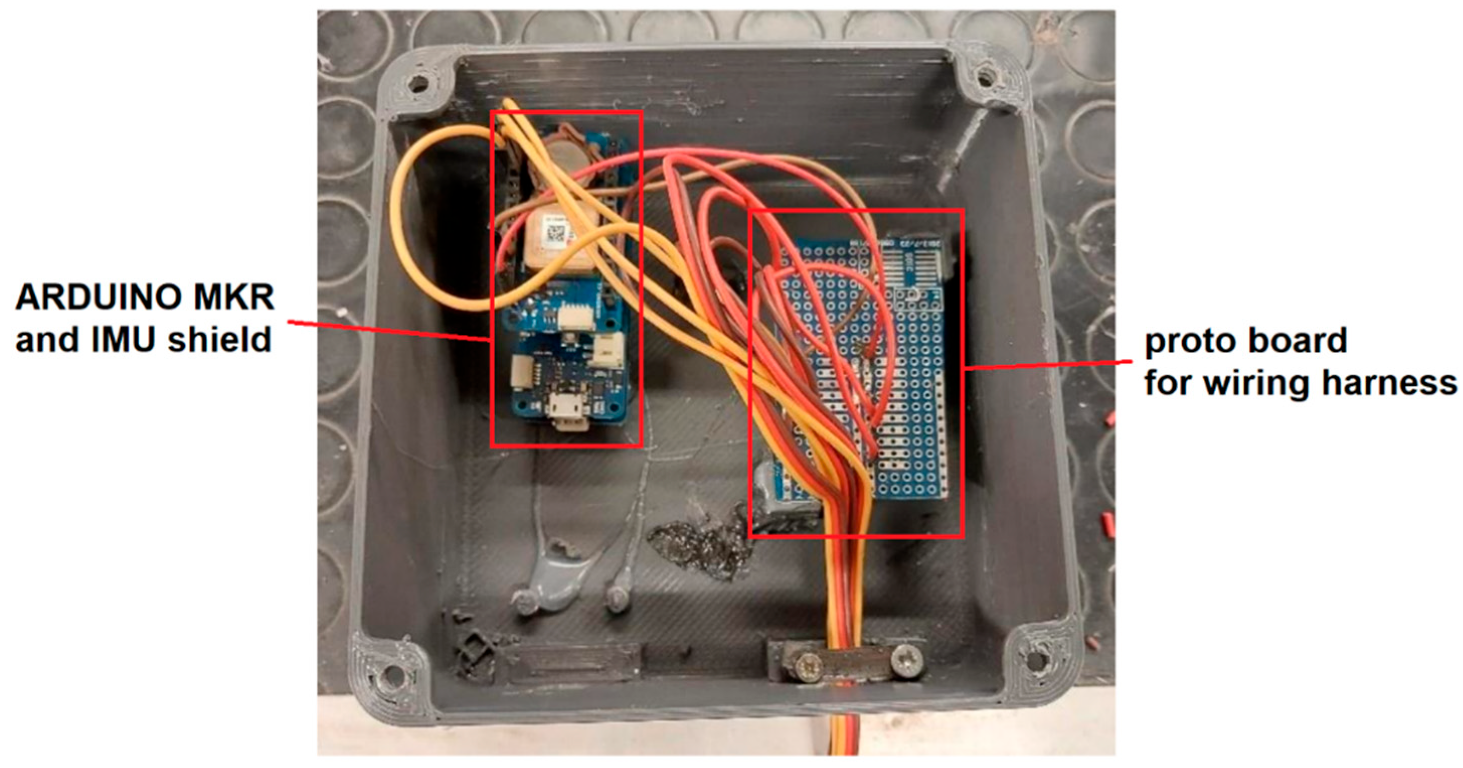
The MKR IMU Shield is based on the BNO055 absolute orientation sensor developed by Bosch Sensortec GmbH. The device integrates a 14-bit triaxial accelerometer, a 16-bit triaxial gyroscope with a range of ±2000°/s, and a triaxial geomagnetic sensor, together with a 32-bit microcontroller running the BSX3.0 FusionLib software. The sensor provides three-dimensional acceleration data, yaw rate, and magnetic field intensity, each measured along three mutually orthogonal axes.
- Wheel sensors
The sensors were modified by positioning the emitter and receiver face-to-face within a shielded configuration, in order to minimize false readings caused by sunlight. They operate by detecting the number of slots in the brake discs. The detection range is between 2 and 30 cm, and the sensitivity can be adjusted through the multi-turn trimmer integrated in the module. Each sensor features three connections: power supply, ground, and a digital output signal (logic 0 or 1). It should be noted that the IR emitter and receiver are aligned such that they are able to ‘see’ each other only when the wheel exposes an open slot in the brake disc.
Figure 8.
Wheel sensor bracket – front wheel with disc reading (10 slot/revolution).
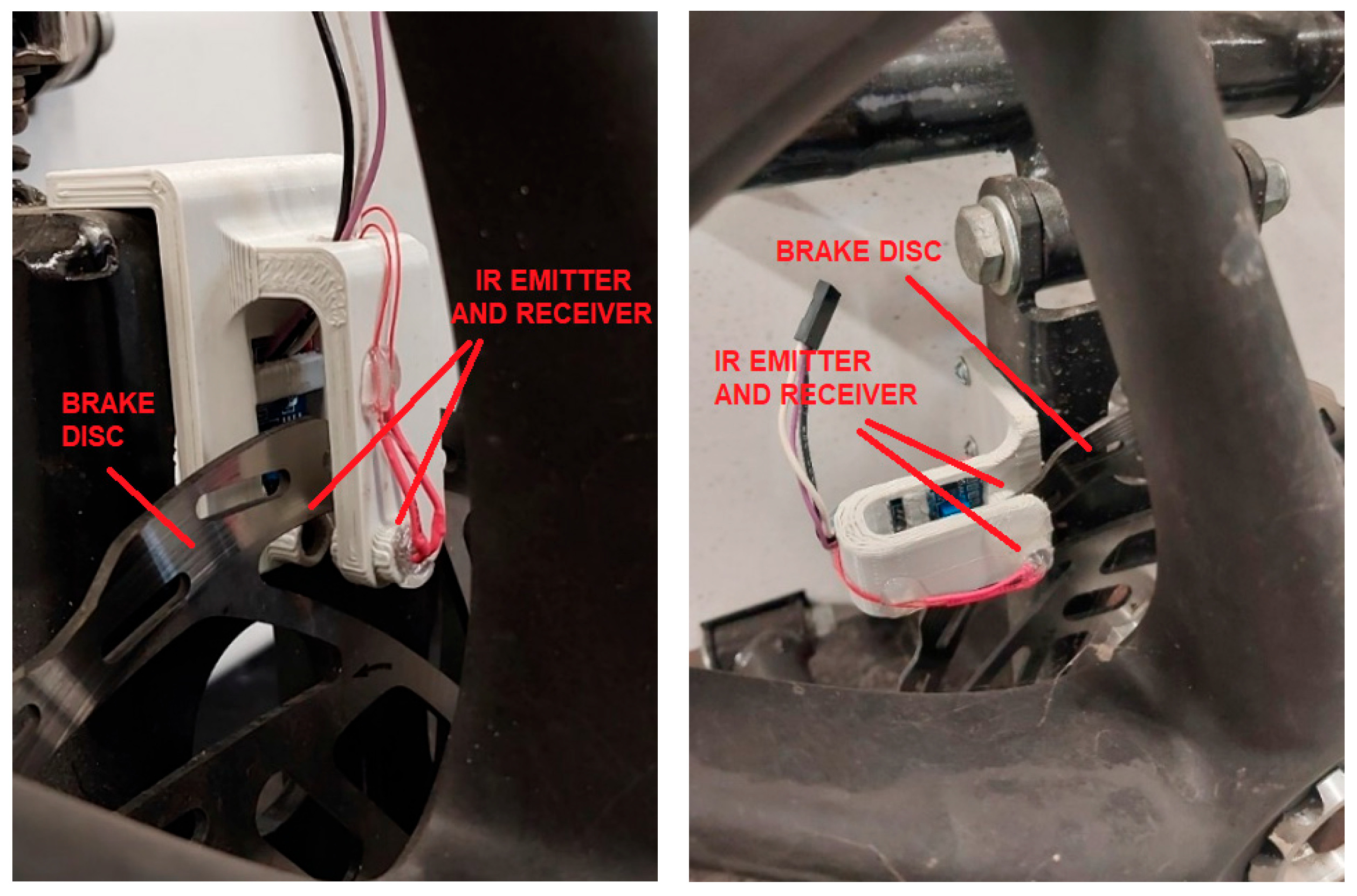
The installation on the rear wheels required slight modifications due to the different hub geometry; however, the operating principle remains the same.
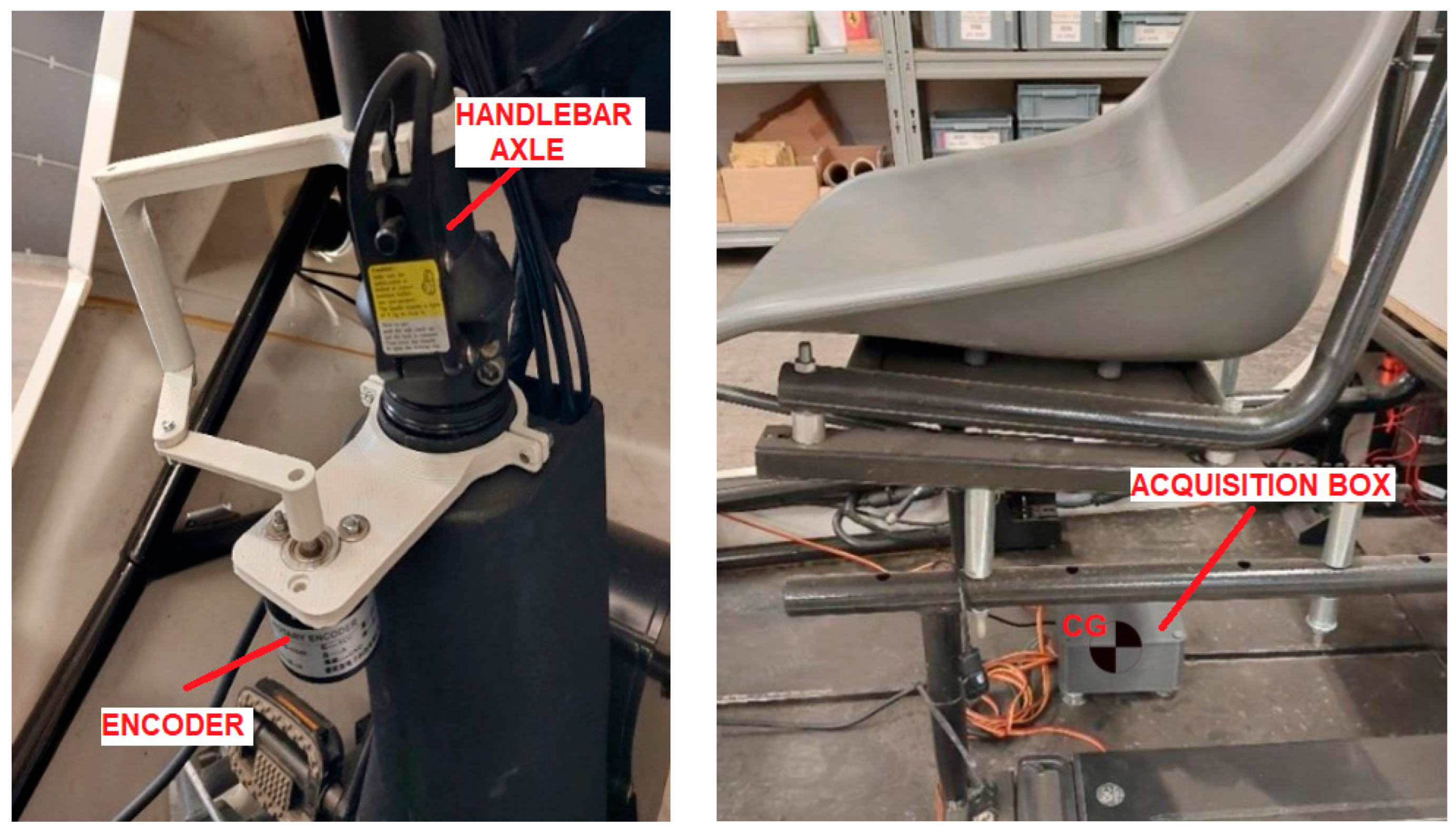
- Steering angle sensor
To measure the steering angle, a linkage mechanism was designed to transmit the motion to an encoder. The selected encoder provides a resolution of 600 pulses per revolution and operates with a supply voltage in the range of 5–24 V.
Figure 9.
On the left the encoder installed in the SNAP vehicle and on the right the acquisition box unit located at the vehicle’s Center of Gravity (CG).
Figure 9.
On the left the encoder installed in the SNAP vehicle and on the right the acquisition box unit located at the vehicle’s Center of Gravity (CG).
After the installation of all sensors and the wiring of the system, the calibration and validation procedures were carried out. Starting with the wheel sensors, the potentiometers were adjusted to ensure that the measured speed matched the actual vehicle speed, as provided by the onboard computer and previously verified via GPS. Subsequently, the correct operation of all other sensors was verified, confirming that the system can acquire data at a frequency of 200 Hz. This rate, however, decreases significantly when the Arduino is required to store data on a microSD card. For this reason, all tests were conducted without on-board storage, transmitting data via serial connection to a PC or an Android device.
4.1. Testing: Moose Test Data Acquisition System Validation (DIN 79010)
As an illustrative example, Figure 11 reports the acquisition performed during a preliminary moose test. As can be observed, the measured data are consistent with the execution of the maneuver as prescribed by the track layout shown in Figure 10.
Figure 10.
Moose test track: sector 1: 6.25m, sector 2: 6.25m, sector 3: 1.95m, sector 4: 5.25m, sector 5: 6.25m.
Figure 10.
Moose test track: sector 1: 6.25m, sector 2: 6.25m, sector 3: 1.95m, sector 4: 5.25m, sector 5: 6.25m.
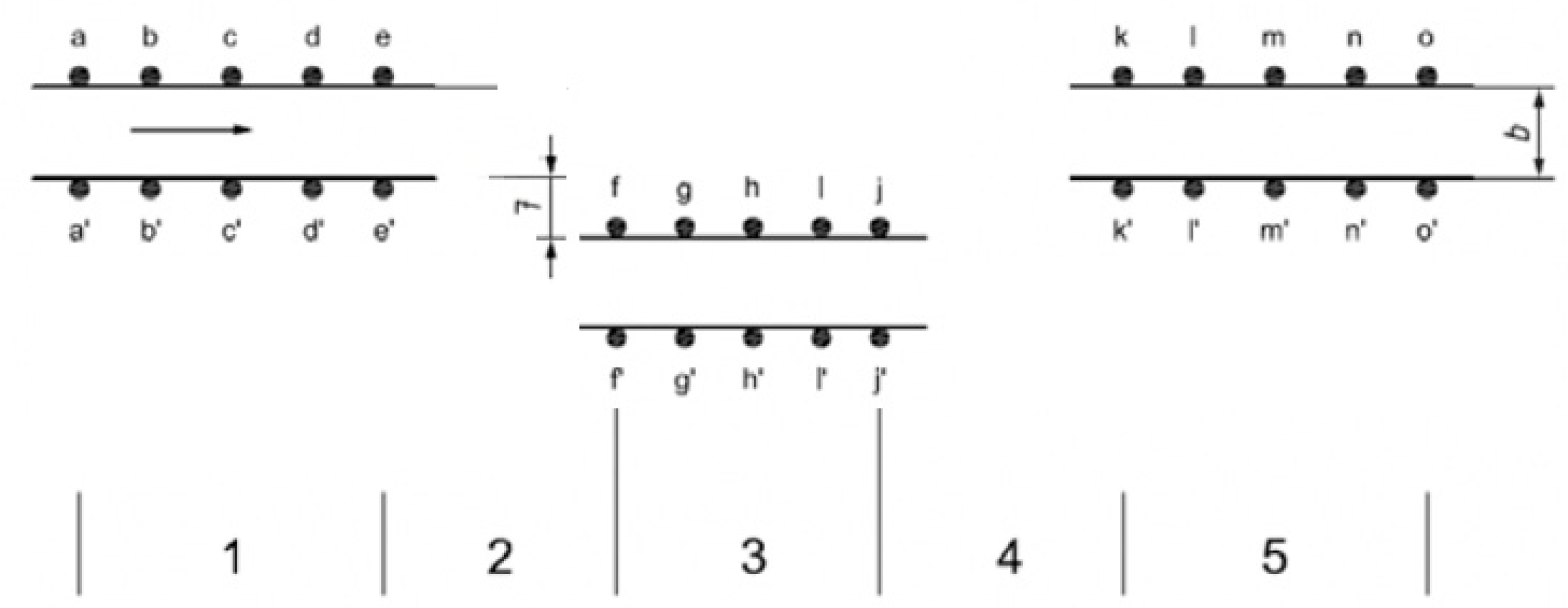
Figure 11.
The data logged with the acquisition box during the test.
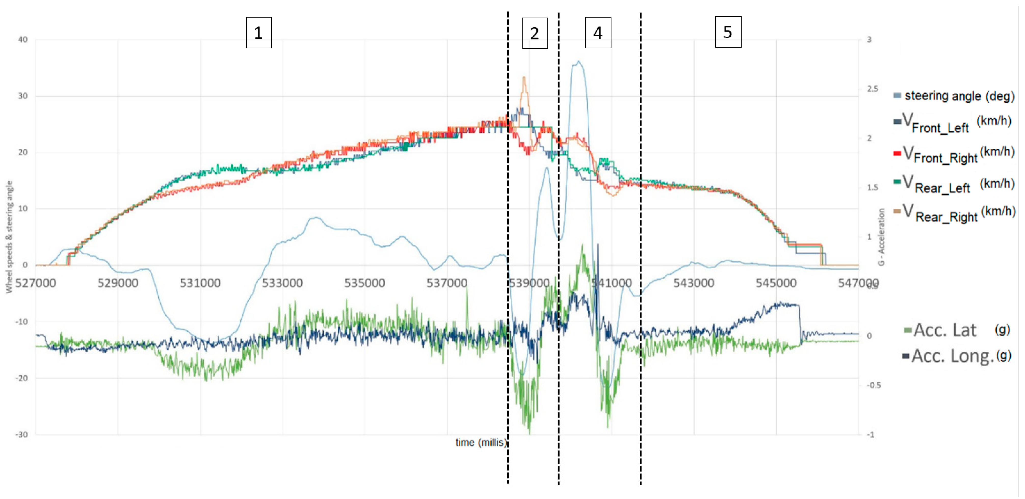
Figure 11 illustrates the different phases of the test, which are also schematically described in Figure 10. In sector 1, the vehicle accelerates in preparation for the moose test. Of particular interest is the longitudinal acceleration of the vehicle and the steering corrections performed to ensure proper alignment within the test area. It can be observed that, when the steering wheel is turned, the inner and outer wheels exhibit different velocities, thereby generating a lateral acceleration component. In sector 2, the steering input produces a sharp increase in lateral acceleration, reaching approximately 0.6–0.7 g. A comparable condition is observed again in sector 4.
Sector 3 cannot be clearly identified in the data, as it corresponds to a straight segment of about 2 meters, which is in fact shorter than the overall length of the vehicle. Finally, Phase 5 is characterized by the deceleration of the vehicle.
4.2. Testing: Straight-Line Stability of the Instrumented Vehicle (DIN 79010)
The primary focus of this study is the straight-line stability test, aimed at evaluating the magnitude of the slip angle in the 1WD configuration with a single in-wheel motor. The objective is to assess whether the induced slip angle may adversely affect the drivability of the vehicle. To enable this comparison, preliminary instrumentation of the vehicles was required.
Tests were carried out on a straight section of track, adopting a configuration with a single driving wheel equipped with an in-wheel motor, in order to evaluate the ‘neutral’ behaviour of the vehicle despite traction being applied only on the right rear wheel.
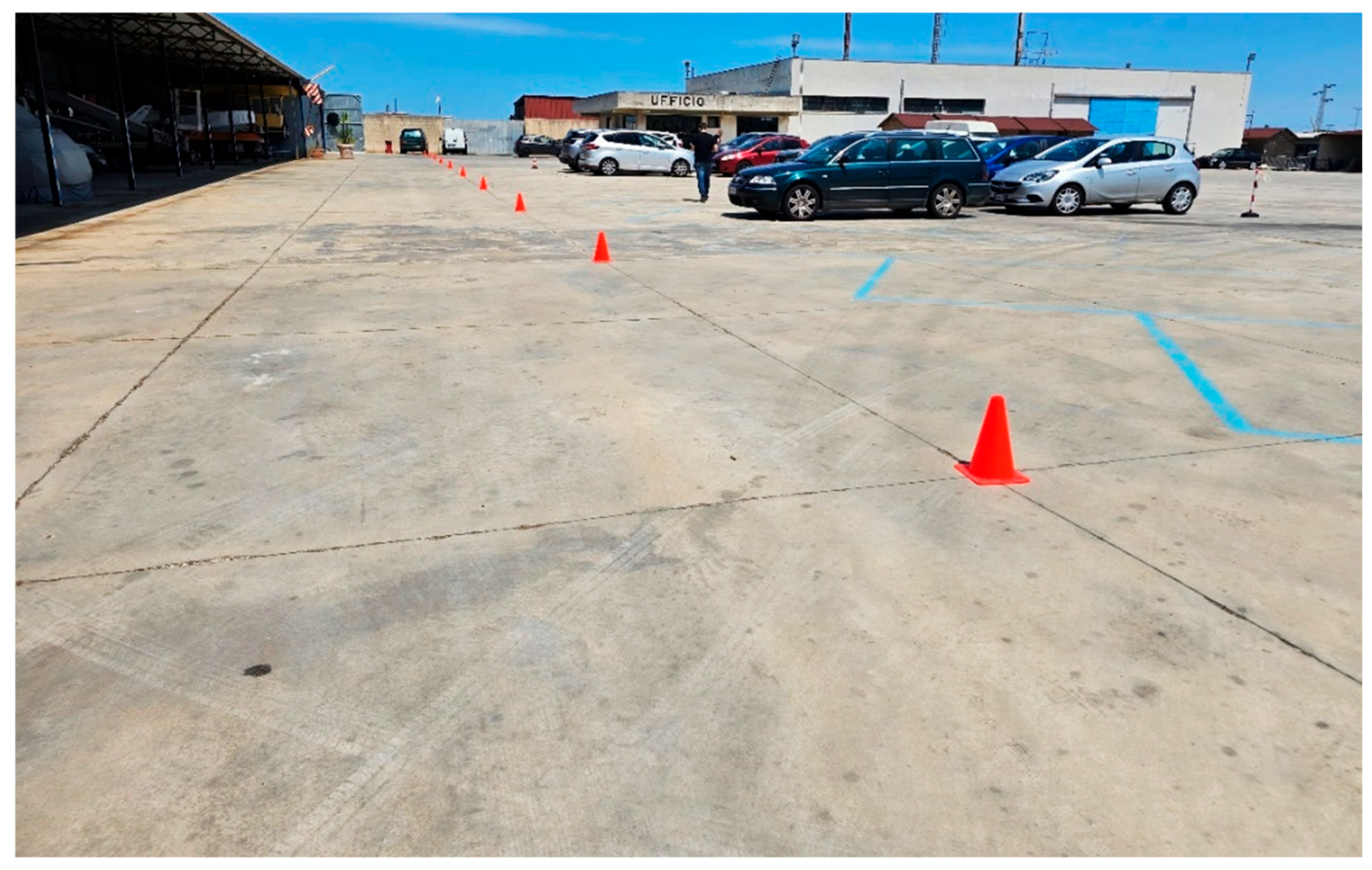
Figure 12.
Test track: straight section of approximately 110 m.
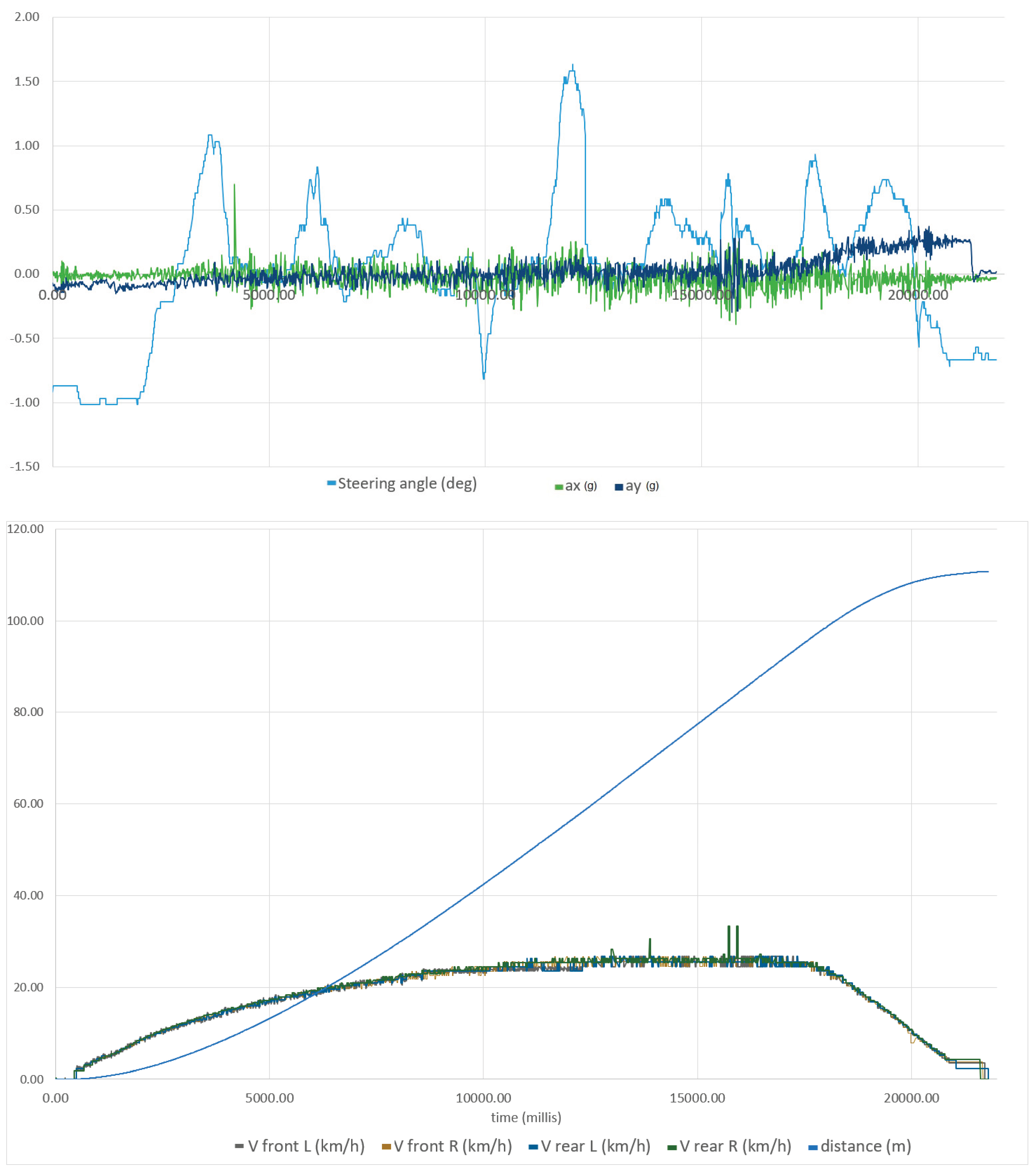
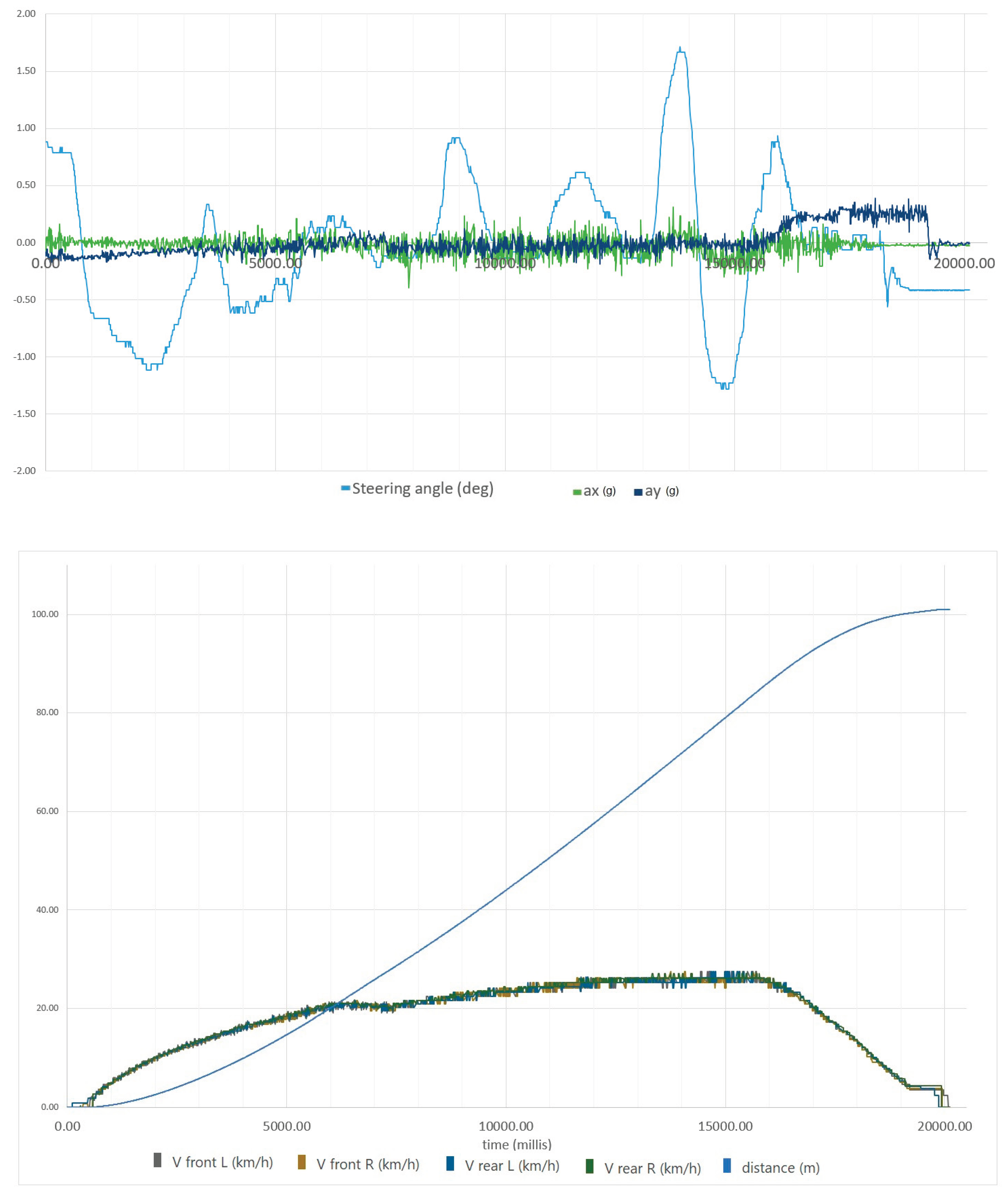
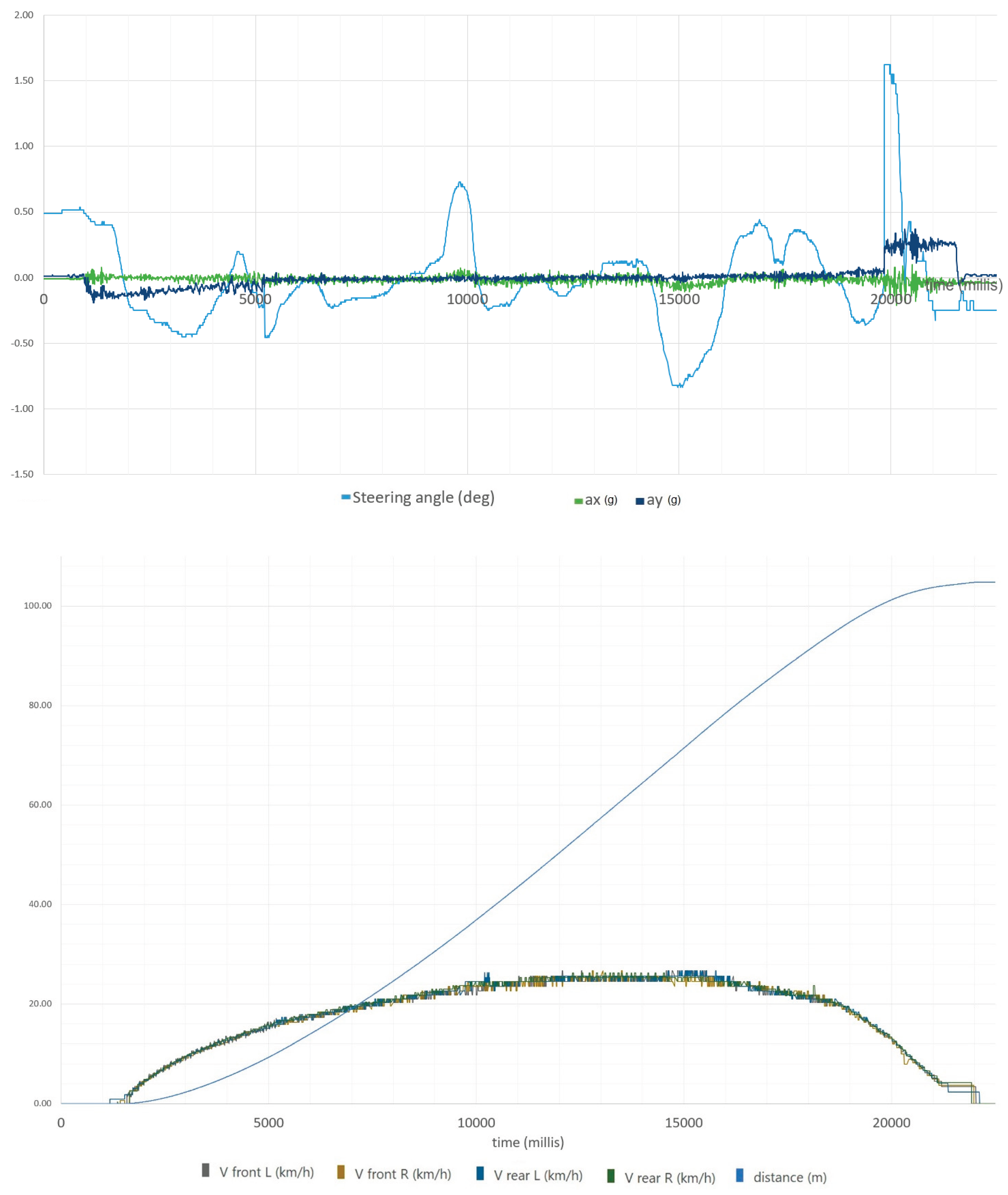
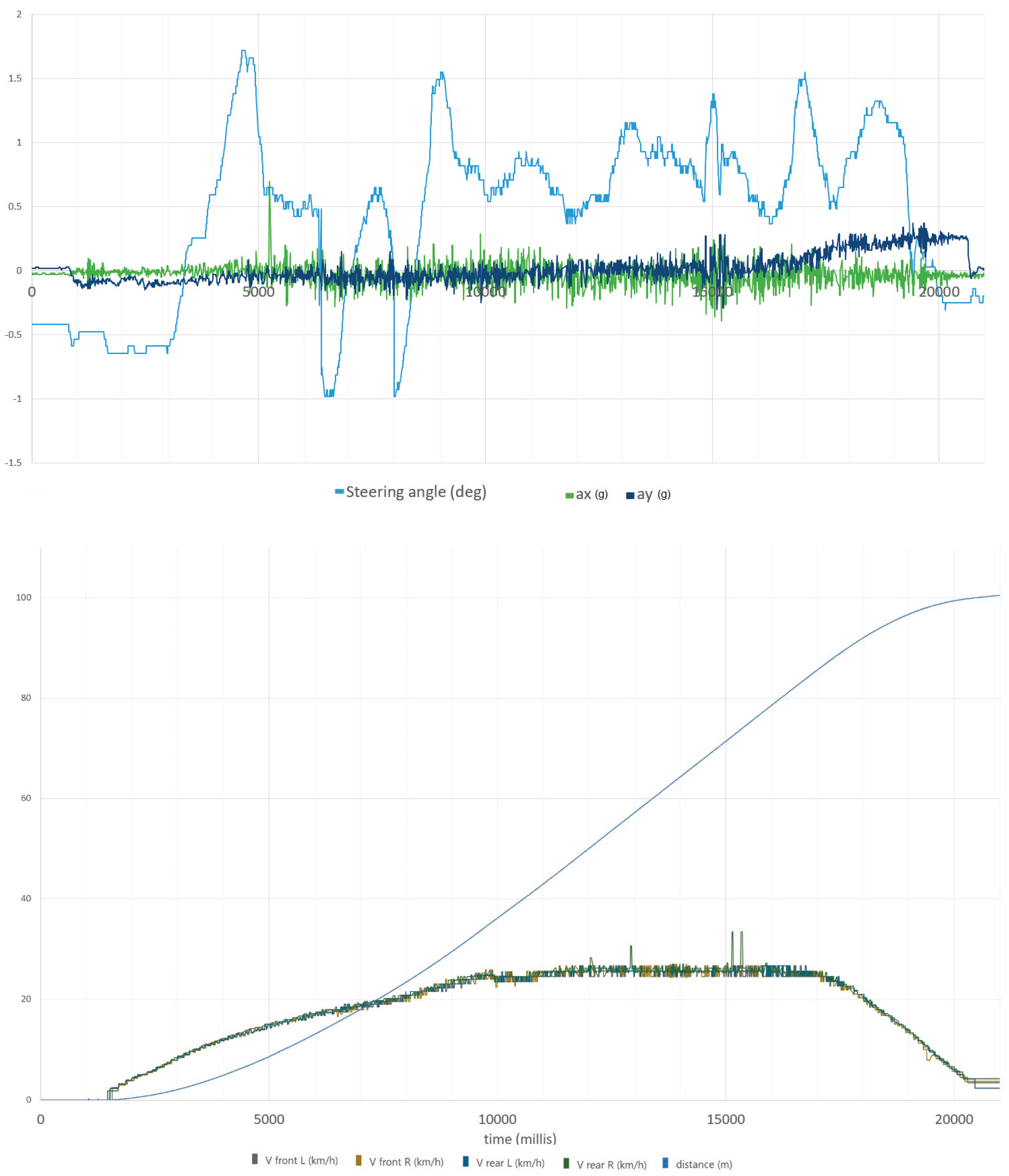
The following plots illustrate in the lower part of the figure, the individual wheel speeds and the overall vehicle distance; in the upper part of the figure, the vehicle accelerations and the steering angle.
-
Test 1: Vehicle in drive-by-wire configuration (1WD) with in-wheel motor.o The mean steering angle was found to be +0.05°o Vfront_L = 18.02 km/h, Vfront_R =18.04 km/h, Vrear_L = 18.07 km/h, Vrear_R = 18.44 km/h
Figure 13.
Data logged during the straight-line test #1.
-
Test 2o The mean steering angle was found to be -0.10°o Vfront_L = 16.78 km/h, Vfront_R =16.71km/h, Vrear_L = 16.80 km/h, Vrear_R = 17.05 km/h
Figure 14.
Data logged during the straight-line test #2.
-
Test 3o The mean steering angle was found to be -0.03°o Vfront_L = 15.19 km/h, Vfront_R =15.08km/h, Vrear_L = 15.26 km/h, Vrear_R = 15.39 km/h
Figure 15.
Data logged during the straight-line test #3.
- Test 4
- o The mean steering angle was found to be +0.36°.
- o Vfront_L = 15.29 km/h, Vfront_R =15.22km/h, Vrear_L = 15.31 km/h, Vrear_R = 15.57 km/h
Figure 16.
Data logged during the straight-line test #4.
In all the tests, as expected, no appreciable speed deviations were observed among the four wheels of the vehicle. Also, no significant evidence of vehicle slip was detected, which would otherwise have manifested as a steering angle compensation required to maintain a straight trajectory.
It should also be noted that the angle measured at the handlebar must be divided by a factor of approximately 1.5 to obtain the actual wheel steering angle. Consequently, the phenomenon described above proves to be even less significant.
An interesting, albeit expected, observation is that the average speed of the driving wheel is slightly higher than that of the free wheels, due to the applied driving torque and the corresponding longitudinal speed.
5. Final Considerations
Throughout this research, the state of the art of sustainable urban mobility was first examined, with a particular focus on the evolution of pedal-assisted vehicles for the transport of goods and passengers. The regulatory framework was subsequently analyzed in greater detail, with special attention to cargo bikes.
The drive-by-wire configuration has demonstrated several advantages over conventional mechanical solutions, including significant structural simplification, increased design flexibility, reduced overall weight, and lower maintenance requirements. Although this architecture is not yet widely established at an industrial scale, both theoretical and experimental analyses confirmed its suitability for urban applications.
The adoption of a single in-wheel driving unit raised concerns regarding the potential onset of a slip angle due to torque asymmetry. However, a simplified mathematical model suggested that this effect would have a negligible impact on the dynamic behavior of the vehicle. This hypothesis was experimentally verified through straight-line stability tests performed on an instrumented prototype, in accordance with DIN 79010 standards. The results confirmed the theoretical predictions: the resulting slip angle was so small as to be undetectable by the measurement equipment. A slight discrepancy in wheel rotational speed was nonetheless observed, attributable to the longitudinal tire slip under traction, with the driving wheel consistently exhibiting approximately +2% higher rotational speed.
The experimental findings demonstrate the full compliance of the drive-by-wire system with current regulatory requirements, including the more stringent assessments such as the “moose test” and the “straight-line stability” test. These results indicate that this architecture represents a highly promising solution for the next generation of lightweight urban vehicles, owing to its efficiency, modularity, and adaptability to diverse use cases. In conclusion, this study confirms that the introduction of innovative drivetrains such as the drive-by-wire system can play a pivotal role in the evolution of sustainable urban mobility, supporting the transition towards safer, and low-emission cities.
CRediT Authorship Contribution Statement
F.P.: Writing – review & editing, Writing – original draft, Validation, Methodology, Investigation, Data curation, Conceptualization. G.M and G.R.: Writing – review & editing, Writing – original draft, Visualization, Methodology, Conceptualization, Supervision, Funding acquisition.
Declaration of Competing Interest
On behalf of all authors, the corresponding author states that there is no conflict of interest. G. Reina and G. Mantriota declare they have no financial interests to disclose. F. Passarella is the CEO of the innovative start-up SNAP and pursuing his research doctorate in urban micro-mobility at the Polytechnic University of Bari.
Data Availability
Data will be made available on request.
Acknowledgments
This work was partially funded by the project PAULA (Pedal-Assisted Urban Lightweight Automobile), PRIN 2022 PNRR (prot. P2022LKJ7Z).
References
- MIT Climate Portal. "How much CO₂ is emitted by manufacturing batteries?" Massachusetts Institute of Technology. https://meche.mit.edu/news-media/how-much-co2-emitted-manufacturing-batteries [Online, 01/03/2022].
- European Environment Agency, "Average CO₂ emissions from new passenger cars" (2024 provisional data). https://www.eea.europa.eu/en/newsroom/news/average-co2-emissions-from-new-cars-and-new-vans [Online; 04/06/2025].
- Santucci, M.; Pieve, M.; Pierini, M. Electric L-category vehicles for smart urban mobility. Transportation Research Procedia 2016, 14, 3651–3660. [Google Scholar] [CrossRef]
- Mantecchini, L.; Costa, N.; Rizzello, V. Last Mile Urban Freight Distribution: A Modelling Framework to Estimate E-Cargo Bike Freight Attraction Demand Share. Future Transportation 2025, 5, 31. [Google Scholar] [CrossRef]
- Telekom IoT Blog. "citkar E-Cargo Bike: IoT Trackers Optimize Last Mile". https://iot.telekom.com/en/blog/iot-trackers-optimize-last-mile [Online, 19/10/2021].
- Electric Assisted Vehicles Ltd. “Eav Cargo Bike”. Electric Assisted Vehicles Ltd. https://eavcargo.com/products/eav-cargo-bike [Online, 2024].
- CityQ, AS. CityQ Car-eBike – Technical Specifications. CityQ official site. https://cityq.biz [Online, 12/08/2024].
- Velove Bikes, AB. Armadillo – Technical Specifications. Velove official site. https://www.velove.se/electric-cargo-bike [Online, 13/07/2022].
- Vok Bikes / Optigon OÜ. Vok S – Technical Specification Sheet. Vok Bikes official site. https://vokbikes.com/wp-content/uploads/2025/05/Vok-S-Technical-Specification-Sheet-23-web.pdf [Online, May 2025].
- Mubea U-Mobility. Urban / Cargo PACK – Technical Specification Sheet. Mubea official site. https://www.mubea-umobility.com/en/media/180/download?inline= [Online, 10/2024].
- Passarella, F.; Mantriota, G.; Reina, G. Introducing SNAP: a novel pedal-assisted electric ultralight vehicle. SN Applied Sciences 2022, 5. [Google Scholar] [CrossRef]
- F. Passarella, G. Mantriota, G. Reina, "Overturning stability for the SNAP cargo Family of Pedal-Assisted Ultralight Vehicles", Proceedings of the I4SDG workshop, May 2023.
- D’hondt, J.; Slaets, P.; Demeester, E.; Juwet, M. Pedalling Comfort of a Custom Pedal Series Hybrid Drivetrain in a Cargo E-Tricycle. Engineering Science & Technology 2022, 3, 224–239. [Google Scholar] [CrossRef]
- Okoye, I. Ottih, O. Ikwueto, "Performance Evaluation of Pedal Powered Generator for Energy Generation in Nnewi", IOSR Journal Of Applied Physics (IOSR-JAP), e-ISSN: 2278-4861.Volume 13, Issue 2 Ser. III (Mar. – Apr. 2021), PP 01-05, Innoson Kiara Academy, Nnewi, Anambra State, Nigeria, 2021, Department of Physics and Astronomy, University of Nigeria, Department of Industrial Physics, Chukwueme.
- Zhang, S.-P.; Tak, T.-O. Efficiency Evaluation of Electric Bicycle Power Transmission Systems. Sustainability 2021, 13, 10988. [Google Scholar] [CrossRef]
- R. August, R. Kasuba, J.L. Frater, A. Pintz, "Dynamics of Planetary Gear Trains", NASA Contractor Report 3793, June 1984.
- Song, J. Evaluation of driving resistance and energy consumption in electric vehicles under various ambient and tire temperatures using real-world driving data. eTransportation 2025, 16, 100454. [Google Scholar] [CrossRef]
- P. Windes, M. P. Windes, M. Archibald, B. Joseph, "Experimental Determination of Bike Tire Stiffnesses", Grove City College, Grove City, PA 16127, Proceedings of the 2013 ASEE North-Central Section Conference, 2013.
Figure 1.
Top from left: CITKAR, EAV, cityQ. From bottom left Armadillo, Vok, Mubea.
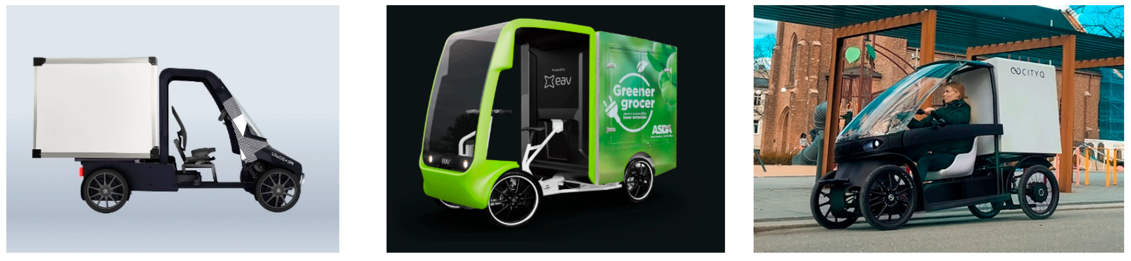
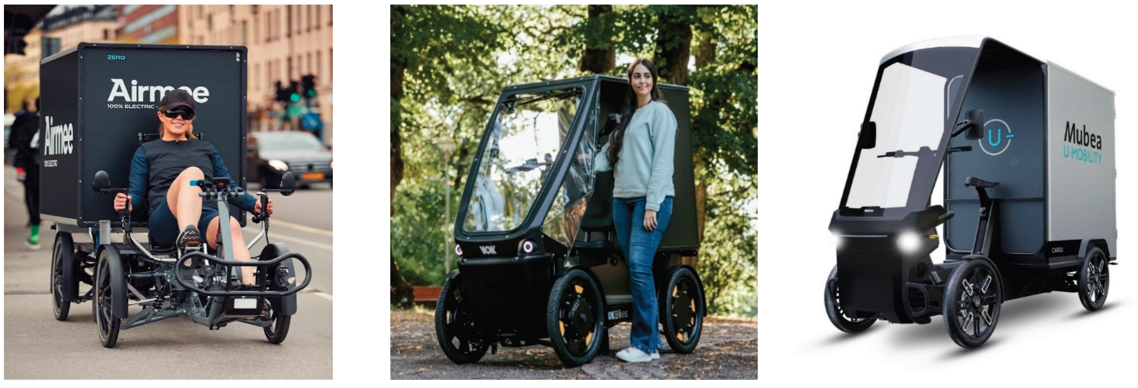
Figure 2.
The electric ultralight quadricycle SNAP during delivery operations.
Disclaimer/Publisher’s Note: The statements, opinions and data contained in all publications are solely those of the individual author(s) and contributor(s) and not of MDPI and/or the editor(s). MDPI and/or the editor(s) disclaim responsibility for any injury to people or property resulting from any ideas, methods, instructions or products referred to in the content. |
© 2025 by the authors. Licensee MDPI, Basel, Switzerland. This article is an open access article distributed under the terms and conditions of the Creative Commons Attribution (CC BY) license (http://creativecommons.org/licenses/by/4.0/).
Copyright: This open access article is published under a Creative Commons CC BY 4.0 license, which permit the free download, distribution, and reuse, provided that the author and preprint are cited in any reuse.


