
Submitted:
23 September 2025
Posted:
24 September 2025
You are already at the latest version
Abstract
A Cantera-based combustion-kinetics framework that maps the operating space of hydro-gen compression-ignition (H₂-CI) engines and establishes a structured charter to guide experiments. Beginning from a diesel (n-dodecane) baseline at an intake temperature of 300 K, the model is virtually converted to neat hydrogen and evaluated across intake tem-peratures of 400–600 K, compression ratios (CR) of 20–28, and exhaust gas recirculation (EGR) levels of 0–15%. Hydrogen demonstrates stable operation across a broad equiva-lence ratio window (ϕ = 0.45–2.1), achieving power outputs of 16–22 kW and higher effi-ciencies with substantially lower fuel mass than diesel. The optimal operating region is identified at approximately 400 K intake temperature, CR = 28, and EGR between 5% and 10%, where power remains high (20–18 kW), efficiency increases (56–57%), and NOx emissions are markedly reduced (from 332 ppm at zero EGR to 48 ppm at 5% EGR and 10 ppm at 10% EGR), with only modest hydrogen slip (0.07–0.11). The kinetics-based frame-work thus provides a systematic and validated roadmap for experimental calibration, re-placing empirical trial-and-error with numerically defined performance and emissions targets.
Keywords:
hydrogen
; engine
; emission
; clean energy
1. Introduction
1.1. Literature Review
Hydrogen Internal Combustion Engines (HICE) were initially developed in 1820 by Reverend W. Cecil[1,2,3], who introduced an automatic engine using a hydrogen-air mixture with a vacuum mechanism. hydrogen has never been commercially viable due to its short flammability range, high autoignition temperature, rapid flame speed, significant diffusivity, low density, and requirement of high compression ratios [4,5,6]. The high compression ratio associated with temperature increase is essential for hydrogen-fueled compression ignition engines. These characteristics highlight that pre-ignition presents a considerable challenge in hydrogen engines due to its low ignition energy, extensive flammability range, restricted quenching distance, and presence of hot spot sources, including spark plugs, exhaust valves, deposits, and oil pyrolysis in the combustion chamber.[7,8].
Central injection is the most basic method for reducing the hydrogen engine's compression ratio, but it's linked to pre-ignition and backfire issues [9,10]. hydrogen engines face challenges such as high ignition temperatures and rapid combustion. Strategies include increasing air temperatures, improving compression ratios, and utilizing hybrid methodologies. Direct hydrogen injection improves fuel economy and emissions, but can cause misfires and explosions. Initiatives aim to alleviate these issues. Ikegami and Rosati [11,12] propose injecting minimal pilot fuel to enhance burn stability, which would lead to ‘silent burning' due to previous cycles. It would also increase NOx emissions and energy demands through ultra-lean hydrogen-air mixtures. Lee[13] suggested that hydrogen compression ignition can be achieved under extreme conditions with high compression ratios. Still, the operational range is limited, and there is a risk of knocking and backfiring. Homan's hydrogen study indicates that hydrogen compression ignition with a glow plug reduces knocking and increases pressure, but constant use reduces efficiency due to thermal requirements [14]. The study demonstrates that hydrogen compression ignition with a glow plug reduces knocking and increases pressure; however, continuous use reduces efficiency due to the thermal requirements.
The paper summarizes methods to reduce the elevated auto-ignition of hydrogen and the associated high compression ratio, while identifying the optimal input temperature and compression ratio to maximize power and economy Table 1.
1.2. Model of Combustion Kinetics
Cantera, an open-source program for chemical kinetics, was utilized to create the numerical modeling framework for this investigation. Under various compression ratios and input temperatures, hydrogen combustion was simulated using a well-stirred reactor (WSR) model. Setting the input parameters, such as temperature, pressure, equivalence ratio, and fuel-air composition, is the first step in the procedure. The governing ordinary differential equations (ODEs) for mass, energy, and species conservation are then solved after the reactor has been initialized with thermodynamic states. The integrated solvers in Cantera monitor the temperature, heat release rates, and species mole fractions throughout time. This method enables an in-depth examination of combustion kinetics, recording high-resolution emission generation, flame behavior, and ignition delay.
1.3. Novelty and Research Gap
The study aims to develop a combustion kinetics modeling tool to determine the optimal compression ratio and input temperature required for effective hydrogen engine performance. The objective is to create a dependable model that integrates exhaust gas recirculation (EGR) to regulate and reduce NOx emissions commonly associated with hydrogen combustion. This study utilizes Python and Cantera as open-source platforms to provide a versatile and accessible framework for experimental design, engine development, and the optimization of hydrogen combustion systems.
2. Method and Model
2.1. Effects of Compression Ratio and Inlet Temperature on the Performance and Emissions of Hydrogen Engines
This model delineates the parametrization of hydrogen compared to dodecane as fuels in an internal combustion engine, assessing the ideal capabilities of hydrogen in practical applications. The simulation will first utilize n-dodecane as the fuel due to its capacity to sustain combustion at moderate inlet temperatures, which is attributed to its low ignition temperature. This phase establishes a performance baseline for the engine operating at a specific compression ratio without necessitating additional heating. This stage employs the `ndodecane_Reitz.yaml` reaction mechanism, which encompasses the kinetics of dodecane combustion [15,16,17].
Upon achieving the dodecane baseline, the model will transition to modeling the removal of dodecane and utilizing hydrogen as the feedstock. Due to hydrogen's elevated ignition temperature, increasing the input temperature will result in combustion occurring at the same compression ratio. Under these conditions, the model aims to initiate an initial heating phase. The next phase will entail simulating hydrogen combustion using the `gri30.yaml` reaction mechanism for hydrogen. After this phase, we will systematically adjust the hydrogen compression ratio and inlet temperature of the hydrogen-fueled engine. The combustion of hydrogen will be modeled as the final step, tailored for the designed engine. Specific combustion characteristics may produce optimal efficiency values while minimizing nitrogen oxide emissions (NOx), particularly since these emissions tend to increase upon hydrogen ignition. The model establishes a baseline for engine testing with dodecane, transitions to hydrogen, adjusts the initial temperature, and optimizes compression ratios for hydrogen efficiency, Diagrams 1 and 2.
The hydrogen engine operates at approximately 3000 rpm with a compression ratio of 20 during its initial run [8,16]. The simulation utilizes the reaction mechanism Gri30, which contains kinetic data for hydrogen and its associated species. The fuel consists solely of hydrogen and is combined with air (O2:1, N2:3.76) Air is supplied into the system at 450 K and a pressure of 13 bars. In contrast, the outlet pressure is maintained at 1 bar and an ambient temperature of 300 K to simulate the typical expulsion of gases.
The engine's geometry, including piston area, stroke, and crankshaft angles, is determined by characteristics such as displacement volume, piston diameter, and cycle volume at the top dead center (TDC). A sinusoidal velocity profile is enough to represent the engine. To regulate gas intake and exhaust, valves are installed at the inlet and outlet, with specific friction coefficients and times for opening and shutting according to the crank angle. The inlet valve opens at -18 degrees and shuts at 198 degrees, while the outlet valve opens at 522 degrees and closes at 18 degrees. The fuel injector injects hydrogen slightly above the top dead center for efficient combustion. The injector is characterized by its opening and closing timings and primarily functions as a mass flow controller for regulating the quantity of hydrogen fuel (Table 2). The model integrates intricate thermodynamic processes, including heat release and expansion work, which subsequently facilitate atmospheric calculations. The model calculates combustion emissions like carbon monoxide and nitrogen oxides, resulting in reduced emissions. The model simulates a reactor's cylindrical shape, gas inflow and outflow, valve timing, and gas distribution, predicting engine thermodynamics, hydrogen fuel efficacy, and potential environmental harm.
Following the analysis of base diesel fuel and hydrogen fuel, we will investigate the impact of inlet temperature (Tin) and compression ratio (CR) on the heat release rate, expansion power, efficiency, and emissions the engine produces (Diagram 1). This method utilizes hydrogen as the primary fuel in an engine, and adjusting the input temperature and compression ratio can modify the operating conditions. The input temperature affects the engine's heat release and power-generating capability, while the compression ratio affects the air-fuel mixture's temperature, density, efficiency, and emissions levels. Elevating both inlet temperature and compression ratio can enhance heat and power output, but also increase nitrogen oxide generation, a significant issue in hydrogen combustion.
Diagram 1.
Internal Combustion Engine Simulation Workflow Using Cantera.
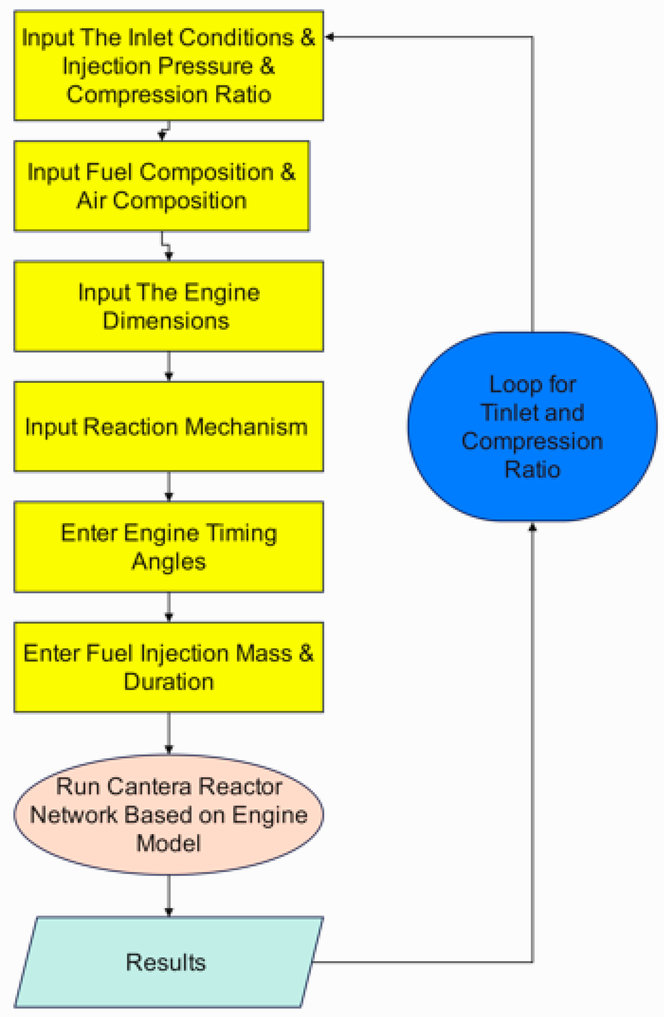
Diagram 2.
Combustion Mechanisms and NOx Chemistry in the Model [18,19].
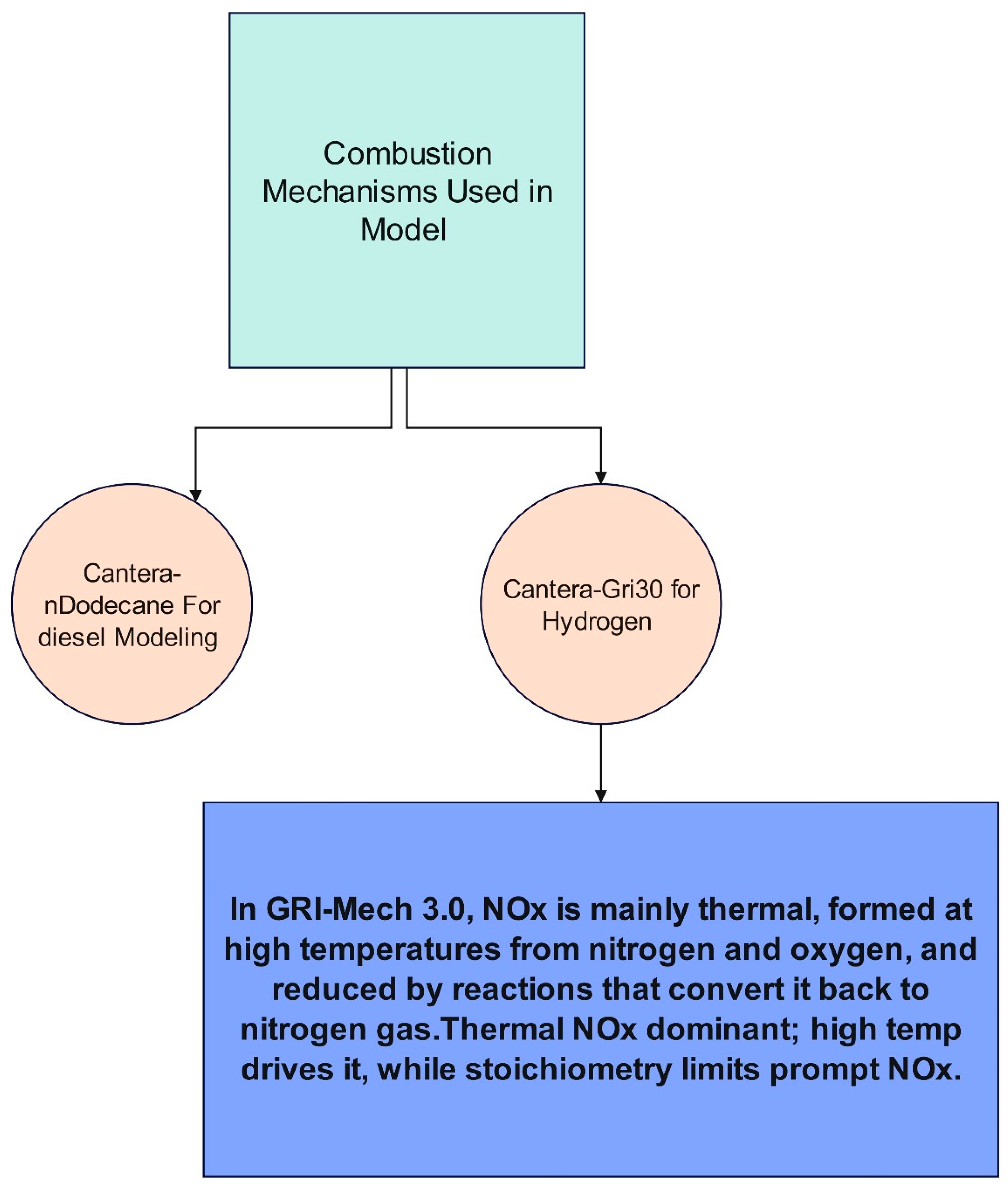
Diagram 3.
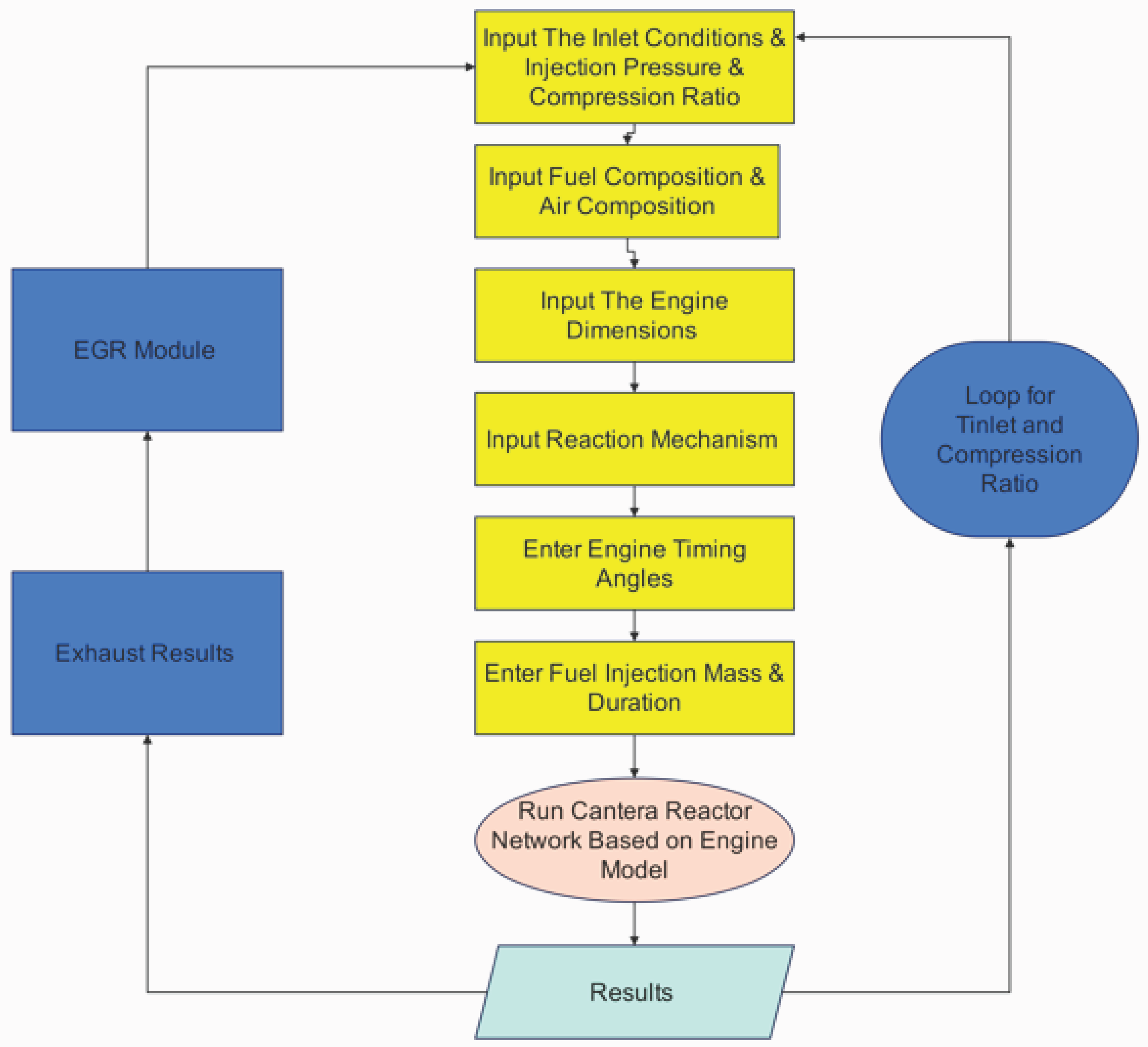
The EGR code flowchart for calculating the percentage effect of EGR on performance and emissions.
Diagram 3.
The EGR code flowchart for calculating the percentage effect of EGR on performance and emissions.
This model is an expanded and reprogrammed version of the Cantera engine example found in the "Diesel-type internal combustion engine simulation with gaseous fuel" section of the Reactor Networks library[16]. This framework is modified in our reprogrammed version to enable the systematic assessment of dodecane (using the Reitz mechanism) and hydrogen (using the GRI-Mech 3.0 mechanism) as fuels.
The code extends the input flexibility and output diagnostics while maintaining the key components of the Cantera architecture, such as cycle tracking, valve and injector modeling, reactor network formulation, and piston wall motion. Heat release, expansion power, efficiency, and emissions are among the integral findings that are calculated by the updated implementation. The robust calculation of the equivalency ratio at intake valve closing enables correct representation in situations with variable exhaust gas recirculation.
The model now offers a comparison platform to examine combustion kinetics, cycle efficiency, and pollutant trends for various fuels.

Table 2.
Detailed Explanation of the Reprogrammed Cantera Internal Combustion Engine Model for Hydrogen (GRI-Mech 3.0) and Dodecane (Reitz Mechanism).
Table 2.
Detailed Explanation of the Reprogrammed Cantera Internal Combustion Engine Model for Hydrogen (GRI-Mech 3.0) and Dodecane (Reitz Mechanism).
| Aspect | Hydrogen (GRI-Mech 3.0) | Dodecane (Reitz mechanism) | Explanation & Main Factors |
| Reaction mechanism | Uses GRI-Mech 3.0, widely validated for hydrogen and natural gas. | Uses Reitz mechanism, validated for heavy hydrocarbons like dodecane. | Mechanism defines how the fuel burns, including ignition delay, flame propagation, and pollutant formation. |
| Reactor type | Treated as a well-stirred cylinder with variable volume. | Same approach. | Assumes gas inside is uniform in temperature, pressure, and composition. |
| Geometry & piston motion | Volume changes based on compression ratio and piston speed profile. | Same. | The piston movement compresses and expands the charge, driving the cycle. |
| Cycle events | Intake, injection, combustion, and exhaust triggered by crank angle timing. | Same. | Valves and injector open and close at specific crank angles. |
| Fuel injection | Hydrogen injected as gas; injector delivers the required mass during the open period. | Dodecane injected as gaseous equivalent in this model. | Ensures correct fuel mass each cycle; in reality, dodecane would involve spray and evaporation. |
| Inlet and outlet valves | Connect the cylinder to inlet and exhaust reservoirs. | Same. | Flow depends on valve opening and pressure difference. |
| Piston model | Moving wall imposes cylinder volume change. | Same. | Converts thermodynamic pressure into piston work. |
| Chemistry solver | Uses a stiff numerical solver to handle fast hydrogen reactions. | Same solver applied to dodecane chemistry. | Ensures stability during rapid ignition and combustion. |
| Numerical stability | Controlled with tight tolerances and a temperature rise limit per step. | Same approach. | Prevents the solver from diverging during heat release. |
| Cycle tracking | Eight engine revolutions simulated with resolution of one degree crank angle. | Same. | Captures full intake–compression–combustion–expansion–exhaust sequence. |
| Heat release | Calculated from hydrogen reaction rates inside the cylinder. | From dodecane reactions. | Represents the chemical energy released from fuel. |
| Work and power | Expansion work integrated over the piston cycle; average power derived. | Same method. | Converts cylinder pressure and piston movement into mechanical output. |
| Efficiency | Ratio of useful expansion work to total heat released. | Same. | Provides a cycle efficiency estimate (idealized, no friction or heat losses). |
| Emissions | Mainly water and nitrogen oxides; carbon monoxide is negligible. | Carbon monoxide and soot are significant, plus nitrogen oxides. | Hydrogen burns clean but can form high NOx at high temperatures; dodecane produces carbon emissions and particulates. |
| Equivalence ratio (mixture richness) | Calculated based on hydrogen injected compared to oxygen or air available at intake closing. | Calculated based on dodecane injected compared to oxygen or air available at intake closing. | Expresses whether the mixture is lean, stoichiometric, or rich. |
| Combustion kinetics main dependencies | Strongly dependent on temperature, pressure, mixture richness, and exhaust gas recirculation. | Same dependencies, with additional influence from evaporation and mixing of liquid fuel. | These factors control ignition timing, flame development, and pollutant levels. |
Table 2.
Comparison of Diesel and hydrogen engines, emphasizing the influence of temperature on power output and efficiency.
Table 2.
Comparison of Diesel and hydrogen engines, emphasizing the influence of temperature on power output and efficiency.
| Parameter | Diesel Engine (n-dodecane) | hydrogen Engine |
| Reaction Mechanism | ndodecane_Reitz.yaml | gri30.yaml |
| Fuel Composition | C12H26:1 (n-dodecane) | H2:1 (hydrogen) |
| Inlet Temperature (K) | 300 | 400 |
| Compression Ratio (ε) | 20 | 20 |
| Engine Speed (rpm) | 3000 | 3000 |
| Displaced Volume (m³) | 5.00E-04 | 5.00E-04 |
| Piston Diameter (m) | 0.083 | 0.083 |
| Expansion Power (kW) | 18.5 | 19.5 |
| Heat Release Rate (kW) | 33.6 | 37.2 |
| Efficiency (%) | 55.2 | 52.3 |
| CO Emission (ppm) | 8.9 | 0 |
| Inlet Valve Angle (deg) | -18 (open) to 198 (close) | -18 (open) to 198 (close) |
| Outlet Valve Angle (deg) | 522 (open) to 18 (close) | 522 (open) to 18 (close) |
| Injector Angle (deg) | 350 (open) to 365 (close) | 350 (open) to 365 (close) |
2.2. EGR Modeling in a Hydrogen Engine
In this work, the inlet conditions under exhaust gas recirculation (EGR) were generated by blending the fresh intake air stream with a fraction of the engine exhaust products. For each operating point, the exhaust composition (N₂, H₂, H₂O, NOx) and temperature were combined with the baseline intake air (O₂/N₂ mixture at the prescribed intake temperature). The EGR fraction determined the relative weighting of exhaust and air, such that higher EGR increased the inlet temperature while diluting the oxygen concentration and introducing combustion products such as H₂O and NOx. The final mixture was normalized to represent the effective inlet composition supplied to the cylinder. This procedure reflects the physical role of EGR in elevating intake temperature, reducing oxygen availability, and modifying the charge chemistry.
The method establishes an operating matrix for a hydrogen-fueled engine by combining intake air with different fractions of recirculated exhaust gas (EGR). For each case, the inlet mixture is defined by its temperature (after blending fresh air and hot exhaust) and by its composition, including oxygen, nitrogen, recirculated water vapor, residual hydrogen, and NOx. These inlet conditions are then used as the boundary state for the engine cycle at different compression ratios and EGR levels.The engine is supplied with hydrogen fuel at fixed injection timing and mass, while the intake mixture varies according to the EGR percentage. The simulation tracks how this modified charge influences combustion, work output, and emissions. After each cycle, the model reports expansion power, thermal efficiency, the amount of unburned hydrogen, and the change in NOx between inlet and exhaust.In this way, the inlet table provides a structured framework to study how EGR alters intake temperature, reduces oxygen availability, and recirculates combustion products, and how these combined effects impact hydrogen engine performance and emissions across a wide range of operating points.
3. Results and Discussion
3.1. Comparison of Performance and Combustion Characteristics of Diesel and Hydrogen Engines
Figure 1 compares the cylinder expansion power as a function of injected fuel mass for hydrogen and dodecane. The vertical bars show simulation data points, while the smooth curves represent quadratic fits capturing the overall trend. With the following Key insights:
- Fuel mass requirement: Hydrogen achieves comparable peak power (~21 kW) with much less injected mass (6–28 ×10⁻⁶ kg) compared to dodecane (25–35 ×10⁻⁶ kg). This reflects hydrogen’s high specific energy per unit mass of oxidizer.
- Operational window: Hydrogen sustains stable combustion across a broader mass range. At the same time, dodecane is more limited and sensitive to over- or under-fueling, while hydrogen could operate in a wide span of equivalence ratio with a chance to decrease NOx in fuel-lean mixtures.
- Intake conditions: Dodecane ignites reliably at 300 K intake, while hydrogen requires preheating to ~400 K to ensure stable combustion. Once ignited, hydrogen’s broad flammability and rapid kinetics allow operation over richer conditions with efficiency advantages.
Figure 2 shows how indicated efficiency varies with the injected fuel mass for hydrogen and dodecane. The bars represent simulation data points, while the smooth curves are quadratic fits. With the following observations:
- Hydrogen: Efficiency remains above 50% across the entire fueling range, climbing steadily to a maximum of ~66% at the richest condition (≈ 2.8 ×10⁻⁵ kg injected). This demonstrates hydrogen’s capability to maintain high efficiency even at elevated equivalence ratios, due to fast kinetics and the absence of carbon-based incomplete combustion losses.
- Dodecane: Efficiency peaks lean (~57% at 2.5 ×10⁻⁵ kg injected) but drops near stoichiometry, falling to ~52–55% as fueling increases. This reflects increasing CO and incomplete oxidation penalties at higher injection masses.
- Comparative insight: Hydrogen delivers a clear efficiency advantage (~9–10 percentage points higher) at rich fueling, while dodecane’s efficiency window is narrower and more sensitive to φ. Hydrogen’s broad stable range offers flexibility for lean- and rich-burn strategies, while dodecane requires careful fueling control to avoid efficiency loss.
This Figure 3 shows the variation of expansion power with equivalence ratio (ϕ), comparing hydrogen and dodecane. Data points are plotted as bars, while smooth fitted curves illustrate overall trends. With the following Key observations:
- Hydrogen: Expansion power peaks at ~21 kW around ϕ ≈ 1.2, and remains relatively high across a broad operating window (ϕ = 0.45–2.1). This highlights hydrogen’s wide flammability limits and robust combustion stability at both lean and rich conditions.
- Dodecane: Power output peaks near 20 kW but within a much narrower range (ϕ = 0.67–0.94). Beyond this region, incomplete combustion and mixture inhomogeneity limit power rise, making the system more sensitive to small fueling changes.
- Comparative insight: While both fuels achieve similar peak power, hydrogen’s broader ϕ operability range allows greater flexibility in engine operation and better tolerance to load or mixture variations. In contrast, dodecane requires tight control near stoichiometric operation, where deviations rapidly reduce performance.
- Practical implication: Hydrogen enables both lean-burn efficiency strategies and rich-burn high-power modes, whereas dodecane is constrained to a narrow stoichiometric band.
Figure 4 compares the variation of thermal efficiency with equivalence ratio (ϕ) for hydrogen and dodecane. The bars represent data from simulation, while the curves show quadratic fits. With the following notes:
- Hydrogen: Efficiency remains above 50% across the entire operating window (ϕ = 0.45–2.08) and increases significantly with richer mixtures, reaching ~66% at ϕ ≈ 2.0. This trend reflects hydrogen’s high reactivity, rapid combustion, and the absence of incomplete carbon oxidation losses.
- Dodecane: Efficiency stays within 52–57% but in a much narrower window (ϕ = 0.67–0.94). Outside this range, combustion is unstable or penalized by incomplete oxidation, limiting its operability.
- Comparative insight: Hydrogen provides a broader and more robust efficiency range, particularly under rich conditions, while dodecane is lean-favoring but tightly bound around stoichiometry.
- Practical implication: The wide ϕ operability of hydrogen makes it suitable for both high-efficiency lean-burn modes and high-power rich-burn modes. Dodecane, on the other hand, requires strict control near stoichiometry to maintain stable and efficient combustion.
3.2. The Effect of Compression Ratio and Inlet Temperature on Engine Performance
As indicated in Figure 5, Efficiency decreases slightly from 400 → 450 K for all compression ratios (CR=20: 52.8→51.5%, CR=24: 53.8→52.5%, CR=28: 56.0→55.3%) because the reduction in charge density outweighs early combustion benefits. Beyond 450 K, efficiency rises steadily as higher Tin improves ignition and combustion phasing, with the most substantial gain at CR=28, reaching ~57.8% at 550 K. This shows that intake heating above 500 K, combined with high compression ratio, enhances efficiency despite the density penalty.
As Indicated in Figure 6, Expansion power increases linearly with compression ratio for all intake temperatures, reflecting the thermodynamic advantage of higher ε. At constant ε, however, power decreases as Tin rises: for ε=20, power falls from 21.0 kW at 400 K to 15.8 kW at 600 K. This loss is caused by reduced air density at higher Tin, which lowers trapped mass and total heat release. Thus, while a higher compression ratio consistently enhances power, elevated Tin imposes a density penalty that dominates over its combustion benefits.
3.3. The Impact of Temperature, Compression Ratio, and Exhaust Gas Recirculation (EGR) on Engine Emissions and Performance
This Figure 7 compares the hydrogen mole fraction at the exhaust outlet as a function of EGR percentage for two compression ratios: CR = 28 (top) and CR = 20 (bottom).
General trend: In both cases, unburned hydrogen increases almost linearly with higher EGR, as recirculated exhaust dilutes the intake oxygen, slowing combustion and leaving more residual H₂.
Impact of intake temperature (Tin): At higher intake temperatures (550–600 K), H₂ slip is markedly higher compared to 400 K, since hotter mixtures promote earlier ignition but reduce complete utilization of injected hydrogen under diluted conditions.At Tin = 400 K, EGR up to 10% keeps H₂ slip moderate (≈0.10–0.11), which is acceptable. At higher Tin (≥500 K), however, even 5–10% EGR results in elevated H₂_out (>0.15), indicating diminishing returns for emissions control.
This Figure 8 shows the variation of NOx production with EGR for two compression ratios: CR = 28 (top) and CR = 20 (bottom).
Sharp NOx reduction with EGR: At both CR levels, NOx falls steeply between 0% and 5% EGR, with diminishing returns beyond 10%. For example, at Tin = 400 K, CR = 20, NOx drops from ~430 ppm (no EGR) to ~65 ppm (5% EGR) and to ~15 ppm (10% EGR).By 10–15% EGR, NOx levels are almost negligible (<5 ppm) across all intake temperatures, demonstrating EGR’s strong role in suppressing thermal NOx pathways.
This Figure 9 illustrates the variation of expansion power with increasing EGR for two compression ratios: CR = 28 (top) and CR = 20 (bottom).Power loss with EGR: In both cases, power decreases almost linearly as EGR increases. This is expected because EGR dilutes the intake charge with inert exhaust gases, lowering the effective oxygen concentration and reducing the combustion heat release.Effect of intake temperature (Tin): Higher Tin values result in lower baseline power. At Tin = 400 K, the power output is highest (22–23 kW at CR = 28, ~21 kW at CR = 20), while at Tin = 600 K, the power drops significantly (13–17 kW). This reflects weaker density of the intake charge and earlier ignition with hotter mixtures.Compression ratio comparison: Increasing CR from 20 to 28 consistently enhances power across all EGR levels by ~1.5–2.0 kW. This improvement is due to better utilization of the fuel energy through higher compression efficiency.Trade-off context: While EGR strongly reduces NOx (as seen in Figure 8), it causes substantial power penalties, especially at higher Tin. The optimal zone lies at moderate EGR (5–10%) where NOx is suppressed effectively but power loss remains acceptable.
Table 3 highlights the trade-offs between power output, hydrogen slip, and NOx mitigation in hydrogen-fueled IC engines. At 400 K and CR = 28, introducing 5% EGR provides the most attractive balance, sustaining 20 kW of power with only modest H₂ slip (0.07) while cutting NOx from over 300 ppm to below 50 ppm. Increasing to 10% EGR further suppresses NOx to near 10 ppm, though power falls by ~2 kW and hydrogen slip increases slightly. Pushing to 15% EGR nearly eliminates NOx emissions but introduces significant hydrogen slip, compromising combustion completeness. At elevated intake temperatures (e.g., 450 K), NOx levels remain controlled at 5% EGR, but both power and hydrogen retention suffer. Comparison across compression ratios shows that higher CR (28) consistently yields stronger performance and efficiency than CR = 24, confirming the benefit of increased compression for hydrogen engines. Overall, the results identify 5–10% EGR at low intake temperature and high CR as the optimum zone, achieving practical NOx reduction while maintaining power density and minimizing hydrogen losses.
4. Validation
4.1. Validation Introduction
Sharma and Dhar [20] performed CFD-based analyses, demonstrating that an increased proportion of hydrogen energy enhances combustion efficiency while simultaneously elevating NOx emissions due to higher flame temperatures. Chintala and Subramanian [21] further established that elevating intake temperatures from 500 K improves combustion efficiency .The existing numerical model corresponds with these observations. This behavior aligns with the experimental findings of Chaichan and Al-Zubaidi [22], which highlighted the efficacy of controlled hydrogen injection and ideal compression ratios in ensuring combustion stability. Recent studies [23,24] endorse the adaptation of traditional CI engines for hydrogen utilization, highlighting the viability of elevated hydrogen injection techniques to enhance performance while mitigating issues like as knocking and pre-ignition.
Our findings indicate that elevating the intake temperature from 400 K to 600 K markedly enhances combustion efficiency by as much as 58.5%, especially at compression ratios exceeding 24:1 and avoid combustion failure noticed clearly at 300 K which is the original dodecane operating temperature .However , this leads to increased NOx emissions, surpassing 500 ppm at higher temperatures and compression ratios, as documented in [20] and [21]..
4.2. Validation Details
Table 4.
Validation of hydrogen Engine Performance Based on Previous Studies.
| Study | Validation of Findings |
| Tsujimura & Suzuki (2017) | hydrogen.CR and intake temperature are , the results emphasize their critical influence on combustion phasing and hydrogen usability in dual-fuel diesel engines.[1] |
| Chintala & Subramanian (2014) | Introducing hydrogen increased the engine’s thermal efficiency but also led to a significant rise in NOx emissions due to hydrogen’s high combustion temperature[21] |
| Rosati & Aleiferis (2009) | In the hydrogen HCCI engine experiment, elevated intake air temperatures (200–400 °C) enabled stable autoignition by compensating for the low compression ratio of the optical engine. This preheating allowed homogeneous combustion without spark or additives. To control NOx, the system operated under lean burn conditions (λ = 1.2–3.0).[12]Supports our numerical result: high CR/intake temp enable ignition. |
| Chaichan & Al-Zubaidi (2015) | An experimental study demonstrated that hydrogen requires higher compression ratios for effective operation in a dual-fuel compression ignition engine. Using a single-cylinder Ricardo E6 engine at 1500 rpm, hydrogen was introduced as a supplementary fuel to diesel. The baseline Higher Useful Compression Ratio (HUCR) for diesel alone was 17.7:1, but this increased when hydrogen was added.[22] Supports our numerical result: high CR/intake temp enable ignition. |
| Lee et al.2013 | It was previously believed that compression ignition of neat hydrogen-air mixtures was impossible due to hydrogen’s high auto-ignition temperature and risk of backfire. However, this study demonstrated successful autoignition at a high compression ratio of 32 under cold start conditions, reduced to 26 under firing. This breakthrough proves hydrogen can ignite without additives [13] Supports our numerical result: high CR/intake temp enables ignition. |
The implementation of Exhaust Gas Recirculation (EGR) in hydrogen internal combustion engines significantly diminishes NOₓ emissions by decreasing in-cylinder temperatures and flame velocity, especially during high-load scenarios.
The model shows a significant reduction in NOₓ emissions with the use of EGR, accompanied by a minimal decline in power output due to intake dilution. These results align with the findings of Lu et al. [25], who established that EGR effectively reduces NOₓ while preserving combustion stability. Kikuchi et al. [26] presented experimental results demonstrating a 51% reduction in NOx, which is consistent with our study. Irimescu et al. [27] similarly demonstrated, through simulation, that low-pressure EGR has significant NOₓ reduction potential in hydrogen engines, especially under urban driving conditions, while circumventing the flow constraints associated with high-pressure systems. The comparisons validate that the existing model precisely represents the impact of EGR on emissions and performance.
Recent experimental studies reinforce the outcomes of our numerical model but often lack a systematic framework. Mohamed et al. [28] demonstrated that hydrogen operation in gasoline direct injection engines sustains lean combustion with near-zero NOx, which aligns with our high-temperature (500–600 K) and EGR ≥ 10% cases where emissions were minimized without efficiency loss. Shamkuwar et al. [29] reported efficiency improvements in diesel–hydrogen dual fuel at high load but with elevated NOx compared to CNG, consistent with our finding that NOx rises sharply at low Tin (400–450 K) without EGR. Similarly, Akhtar et al. [30] showed that hydrogen blending enhanced brake power and torque but required EGR for NOx control, a trend we captured in our CR = 28 runs where power increased and emissions were balanced by moderate recirculation. Musy et al. [31] confirmed the efficiency advantage of direct injection over port injection, which our DI-based model reproduces through efficiency gains at higher CR and Tin. Huang et al. [32] highlighted delayed injection strategies reducing NOx by 88% while improving thermal efficiency, paralleling our observation that EGR delays effective oxygen availability to suppress NOx and sustain η at Tin = 550–600 K. Qin et al. [33] reported accelerated heat release and higher peak pressure with hydrogen addition, in agreement with our CR = 28 baseline showing increased expansion power. Finally, Abdelwahed et al. [34] demonstrated a 10% BTE increase and major reductions in NO, CO, and CO₂ emissions, consistent with our model trends of higher η and improved emission balance under optimized Tin–CR–EGR conditions. Together, these parallels show that while experimental works highlight specific effects of hydrogen fueling, our numerical model organizes them into a coherent charter for combustion kinetics, bridging efficiency, power, NOx, and hydrogen slip in a unified manner.
5. Conclusions
This study demonstrates that hydrogen-fueled compression ignition (H₂-CI) engines, modeled using a Cantera-based framework, can achieve wide operational stability and performance advantages over diesel while introducing unique challenges in emissions control. Across the simulated parameter space of intake temperature (Tin = 400–600 K), compression ratio (CR = 20–28), and EGR levels (0–15%), hydrogen consistently sustained combustion over a broad equivalence ratio window (ϕ = 0.45–2.1), enabling expansion power between 16 and 22 kW and efficiency ranging from 52 to 66%. Compared with dodecane, hydrogen required significantly less fuel mass to achieve similar power outputs and maintained efficiency advantages under both lean and rich fueling conditions, highlighting its versatility and potential for decarbonized engine operation.
The comparative analysis established several key trends. First, increasing CR from 20 to 28 systematically enhanced both power and efficiency across all operating conditions, confirming the thermodynamic benefit of higher compression for hydrogen. Second, intake heating proved essential: while efficiency dipped slightly between 400 and 450 K due to reduced charge density, further heating above 500 K improved combustion phasing and efficiency, peaking near 58% at CR = 28 and Tin = 550 K. However, this efficiency gain was offset by reduced trapped mass, leading to lower power at higher Tin. Thus, while preheating stabilizes hydrogen ignition, excessive inlet temperatures create density-driven penalties in output.
The role of EGR was found to be decisive for balancing NOx emissions against power and hydrogen slip. Without EGR, NOx emissions exceeded 300 ppm at Tin = 400 K and CR = 28, but introducing 5% EGR reduced NOx to ~48 ppm while sustaining 20 kW of power and limiting hydrogen slip to 0.07. Increasing EGR to 10% further suppressed NOx to ~10 ppm with only modest penalties in power (18.1 kW) and acceptable hydrogen slip (0.11). At 15% EGR, NOx was nearly eliminated (~2 ppm), but the trade-off was a sharp decline in power to 16.1 kW and increased slip to 0.15. Elevated Tin compounded these penalties, with higher hydrogen slip and reduced power observed even at moderate EGR.
Overall, the results identify a clear “sweet spot” at Tin ≈ 400 K, CR = 28, and EGR between 5–10%. In this zone, the engine achieves high power density, robust efficiency, and substantial NOx mitigation without incurring excessive hydrogen losses. This contrasts with both higher temperatures, which undermine power, and higher EGR fractions, which sacrifice completeness of combustion.
By systematically quantifying these trade-offs, the study provides a combustion kinetics–grounded charter that can guide experimental calibration and hardware development. Rather than relying on empirical trial-and-error, engine designers can target validated operating points—such as 20 kW, η ≈ 56–57%, and NOx below 50 ppm at 5% EGR—as practical benchmarks for hydrogen retrofits. In this way, the framework serves not only as a validation tool but also as a roadmap to accelerate the transition of hydrogen CI engines from theoretical potential to industrial reality.
6. Standards Refrence
The measured NOₓ concentrations from our engine tests were in the range of 40–80 ppm at full load. These values are considerably below the U.S. EPA NSPS Subpart JJJJ regulatory cap of 250 ppmvd NOₓ at 15% O₂ (dry basis) for stationary spark-ignition internal combustion engines [35]. When compared to the Euro 6 on-road diesel vehicle limit of 0.08 g/km (≈20–60 ppm tailpipe equivalent) [37], as well as the progressive U.S. EPA Tier standards for nonroad/mobile engines that regulate NOₓ in g/kWh terms [36], the results show that the tested engine operates well within U.S. stationary standards and approaches the more stringent European norms. This demonstrates that the engine’s performance is not only compliant but competitive with advanced international benchmarks for NOₓ emissions.
References
- T. Tsujimura and Y. Suzuki, “The utilization of hydrogen in hydrogen/diesel dual fuel engine,” Int J hydrogen Energy, vol. 42, no. 19, 2017. [CrossRef]
- W. H. a. P. H. Stoke, “hydrogen-cum-oil gas as an auxiliary fuel for airship compression ignition engines,” British Royal Aircraft Establishment . Report No. E 3219, , 1930.
- F. H. N. M. S. J. C. Quang Truc Dam, “Modeling and simulation of an Internal Combustion Engine using hydrogen: A MATLAB implementation approach,” Engineering Perspective ISSN: 2757-9077, 2024.
- G. A. Karim, “hydrogen as a spark ignition engine fuel,” Int J hydrogen Energy, vol. 28, no. 5, 2003. [CrossRef]
- Amr Abbass, “hydrogen as a Clean Fuel: Review of Production, Storage, Fuel Cells, and Engine Technologies for Decarbonization,” International Journal of Progressive Research in Engineering Management and Science (IJPREMS), vol. 4, no. 11, 2024.
- Amr Abbass, “hydrogen Integration in Gas Turbines: OEM Innovations and Challenges in Advancing Sustainable Energy Systems,” Journal of Management andEngineering Sciences, 2024.
- K. Wróbel, J. Wróbel, W. Tokarz, J. Lach, K. Podsadni, and A. Czerwiński, “hydrogen Internal Combustion Engine Vehicles: A Review,” 2022. [CrossRef]
- J. Hwang, K. Maharjan, and H. J. Cho, “A review of hydrogen utilization in power generation and transportation sectors: Achievements and future challenges,” 2023. [CrossRef]
- P. Dimitriou, “hydrogen Compression Ignition Engines,” in Green Energy and Technology, vol. Part F1098, 2023. [CrossRef]
- V. M. Domínguez, J. J. Hernández, Á. Ramos, M. Reyes, and J. Rodríguez-Fernández, “hydrogen or hydrogen-derived methanol for dual-fuel compression-ignition combustion: An engine perspective,” Fuel, vol. 333, 2023. [CrossRef]
- M. Ikegami, K. Miwa, and M. Shioji, “A study of hydrogen fuelled compression ignition engines,” Int J hydrogen Energy, vol. 7, no. 4, 1982. [CrossRef]
- M. F. Rosati and P. G. Aleiferis, “hydrogen SI and HCCI combustion in a Direct-Injection optical engine,” in SAE Technical Papers, 2009. [CrossRef]
- K. J. Lee, Y. R. Kim, C. H. Byun, and J. T. Lee, “Feasibility of compression ignition for hydrogen fueled engine with neat hydrogen-air pre-mixture by using high compression,” 2013. [CrossRef]
- H. S. Homan, R. K. Reynolds, P. C. T. De Boer, and W. J. McLean, “hydrogen-fueled diesel engine without timed ignition,” Int J hydrogen Energy, vol. 4, no. 4, 1979. [CrossRef]
- A. T. Kirkpatrick, Internal Combustion Engines: Applied Thermosciences, Fourth Edition. 2020. [CrossRef]
- H. K. M. I. S. R. L. S. and B. W. Weber. David G. Goodwin, “Cantera: An object-oriented software toolkit for chemical kinetics, thermodynamics, and transport processes. https://www.cantera.org, 2023. Version 3.0.0.,” Cantera.
- A. Abbass, “The Numerical Modeling of Internal Combustion Engines with Application to Simulation of Combustion of Single-Cylinder HCCI engine by Cantera and Application of Implementation of an Integrative MATLAB Engine Model and Validation on Waukesha VHP Series Engines,” International Journal of Research Publication and Reviews, vol. 4, no. 10, 2023. [CrossRef]
- C. Li, Y. Wang, B. Jia, Z. Zhang, and A. Roskilly, “Numerical Investigation on NOx Emission of a hydrogen-Fuelled Dual-Cylinder Free-Piston Engine,” Applied Sciences (Switzerland), vol. 13, no. 3, 2023. [CrossRef]
- H. H. W. Funke, N. Beckmann, J. Keinz, and A. Horikawa, “30 Years of Dry-Low-NOx Micromix Combustor Research for hydrogen-Rich Fuels - An Overview of Past and Present Activities,” J Eng Gas Turbine Power, vol. 143, no. 7, 2021. [CrossRef]
- P. Sharma and A. Dhar, “Compression ratio influence on combustion and emissions characteristic of hydrogen diesel dual fuel CI engine: Numerical Study,” Fuel, vol. 222, 2018. [CrossRef]
- V. Chintala and K. A. Subramanian, “hydrogen energy share improvement along with NOx (oxides of nitrogen) emission reduction in a hydrogen dual-fuel compression ignition engine using water injection,” Energy Convers Manag, vol. 83, 2014. [CrossRef]
- T. Chaichan and D. S. M. Al-Zubaidi, “A practical study of using hydrogen in dual – fuel compression ignition engine,” International Publication Advanced Science Journal, vol. 2, pp. 1–10, 2015.
- Efstathios-Al. Tingas, hydrogen for Future Thermal Engines. 2023.
- E. Al Tingas and A. M. K. P. Taylor, “hydrogen: Where it Can Be Used, How Much is Needed, What it May Cost,” in Green Energy and Technology, vol. Part F1098, 2023. [CrossRef]
- Lu, Y., Que, J., Xia, Y., Li, X., Jiang, Q., & Feng, L. (2024). A comparative study of the effects of EGR on combustion and emission characteristics of port fuel injection and late direct injection in hydrogen internal combustion engine. Applied Energy, 375, 123830. [CrossRef]
- Kikuchi, K., Hori, T., & Akamatsu, F. (2022). Fundamental Study on hydrogen Low-NOx Combustion Using Exhaust Gas Self-Recirculation. Processes, 10(1), 130. [CrossRef]
- Irimescu, A.; Vaglieco, B.M.; Merola, S.S.; Zollo, V.; De Marinis, R. Conversion of a Small-Size Passenger Car to hydrogen Fueling: 0D/1D Simulation of EGR and Related Flow Limitations. Appl. Sci. 2024, 14, 844. [Google Scholar] [CrossRef]
- M. Mohamed, S. Vijayaraghavan, and A. Krishnan, “Performance and emission characteristics of a hydrogen gasoline direct injection engine under lean burn conditions,” SAE International Journal of Engines, vol. 17, no. 4, 2024. [CrossRef]
- P. Shamkuwar, A. Khare, and V. Kumar, “Comparative performance and emission analysis of diesel–hydrogen and diesel–CNG dual fuel engines,” International Journal of Hydrogen Energy, vol. 50, no. 5, 2025. [CrossRef]
- S. Akhtar, R. Ahmad, and H. Khan, “Experimental investigation on performance enhancement and NOx control of a dual-fuel diesel–hydrogen engine,” Energy Reports, vol. 11, pp. 5520–5535, 2025. [CrossRef]
- P. Musy, A. Rossi, and C. Boulouchos, “Direct injection versus port fuel injection in hydrogen-fueled internal combustion engines: Efficiency and emission trade-offs,” Fuel, vol. 354, 2025. [CrossRef]
- Y. Huang, L. Zhang, and T. Zhao, “Influence of injection timing on NOx reduction in a direct-injection hydrogen engine,” Applied Energy, vol. 347, 2025. [CrossRef]
- X. Qin, H. Wang, and Y. Chen, “Combustion characteristics and heat release analysis of a hydrogen-assisted compression ignition engine,” International Journal of Engine Research, vol. 26, no. 3, 2025. [CrossRef]
- A. Abdelwahed, M. El-Sayed, and K. Mahmoud, “Improving brake thermal efficiency and reducing emissions in hydrogen-fueled CI engines: An experimental approach,” Energy Conversion and Management, vol. 307, 2025. [CrossRef]
- U.S. Environmental Protection Agency (EPA), 40 CFR Part 60, Subpart JJJJ — Standards of Performance for Stationary Spark Ignition Internal Combustion Engines, Washington, DC, USA. [Online]. Available: https://www.ecfr.gov/current/title-40/chapter-I/subchapter-C/part-60/subpart-JJJJ.
- European Commission, Regulation (EC) No. 715/2007 of the European Parliament and of the Council on type approval of motor vehicles with respect to emissions from light passenger and commercial vehicles (Euro 5 and Euro 6), Official Journal of the European Union, L 171/1, June 29, 2007. [Online]. Available: https://eur-lex.europa.eu/legal-content/EN/TXT/?uri=CELEX:32007R0715.
- U.S. Environmental Protection Agency (EPA), Emission Standards Reference Guide: EPA Emission Standards for Nonroad Engines and Vehicles (Tier 1–4), Washington, DC, USA. [Online]. Available: https://www.epa.gov/emission-standards-reference-guide/epa-emission-standards-nonroad-engines-and-vehicles.
Figure 1.
Expansion Power vs Fuel Mass for Hydrogen and Dodecane.
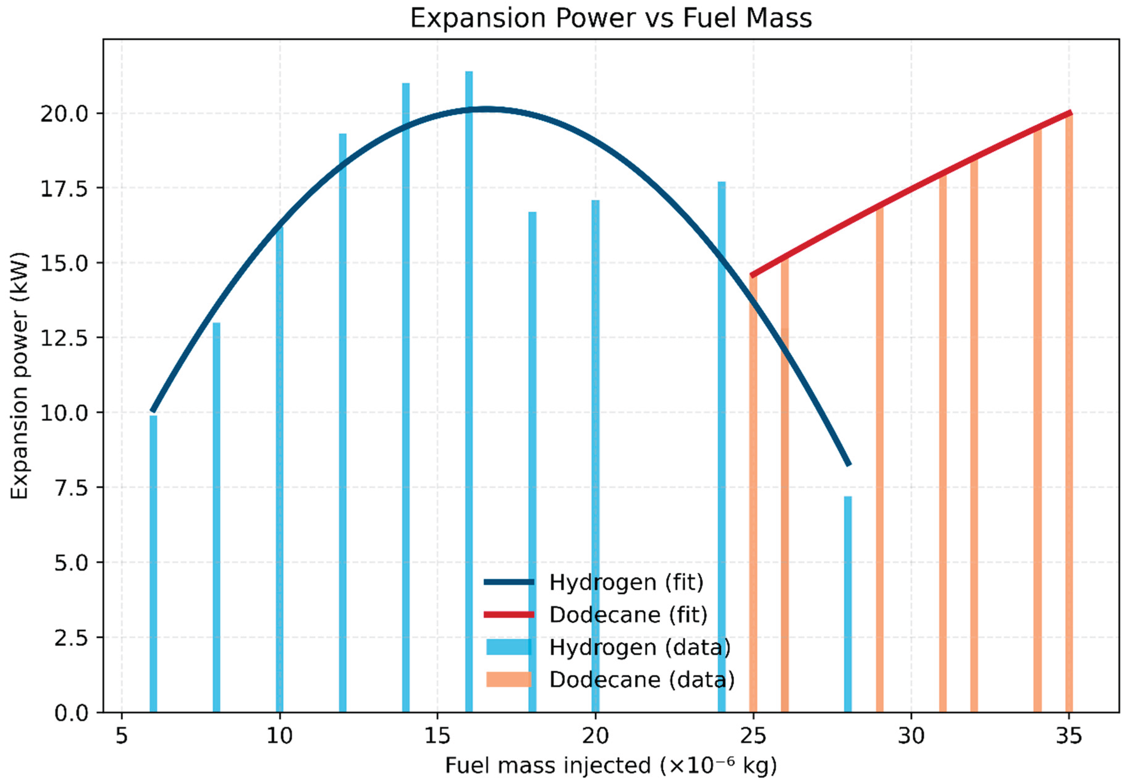
Figure 2.
Efficiency vs Fuel Mass for Hydrogen and Dodecane.
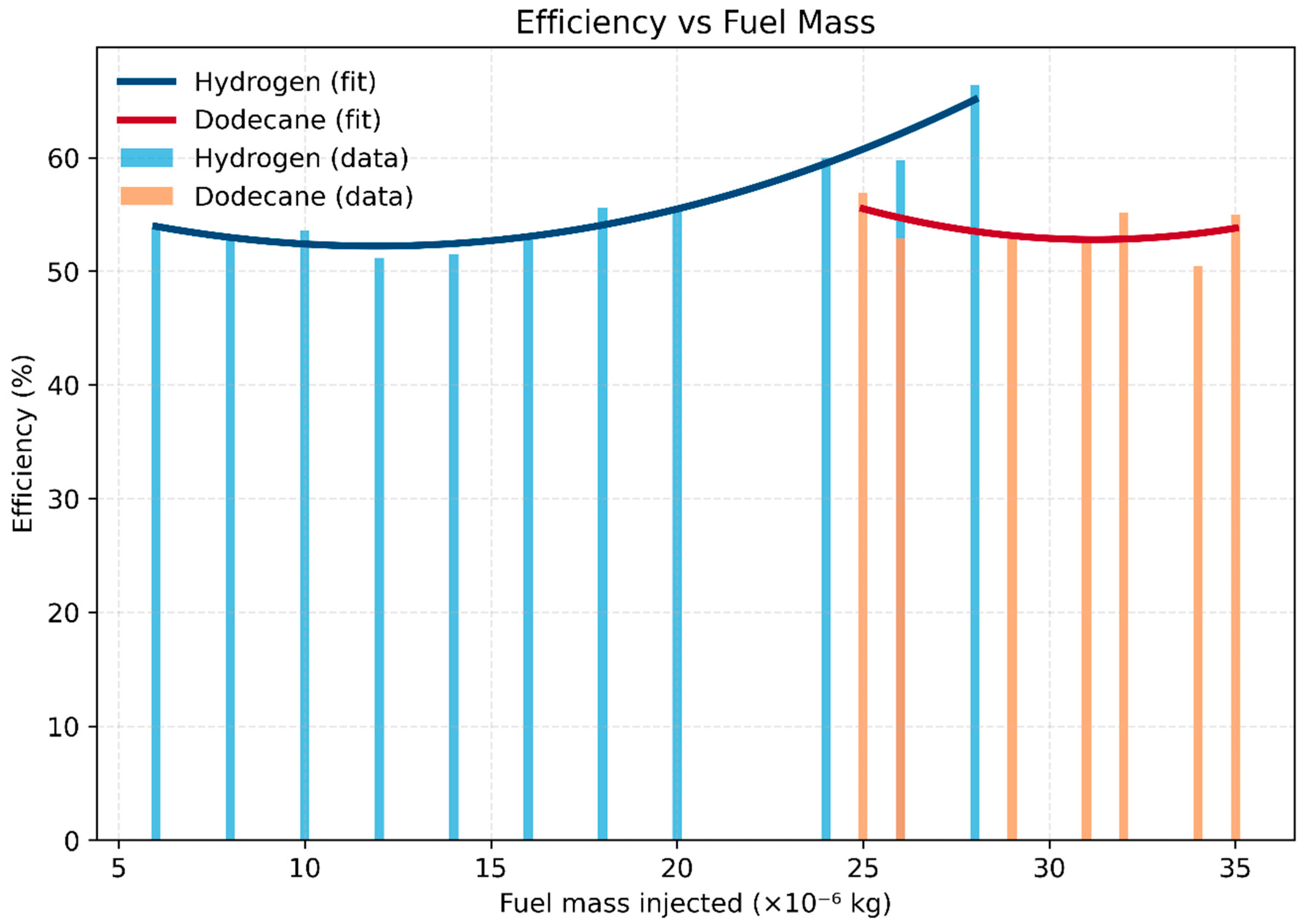
Figure 3.
Expansion Power vs Equivalence Ratio (ϕ) for Hydrogen and Dodecane.
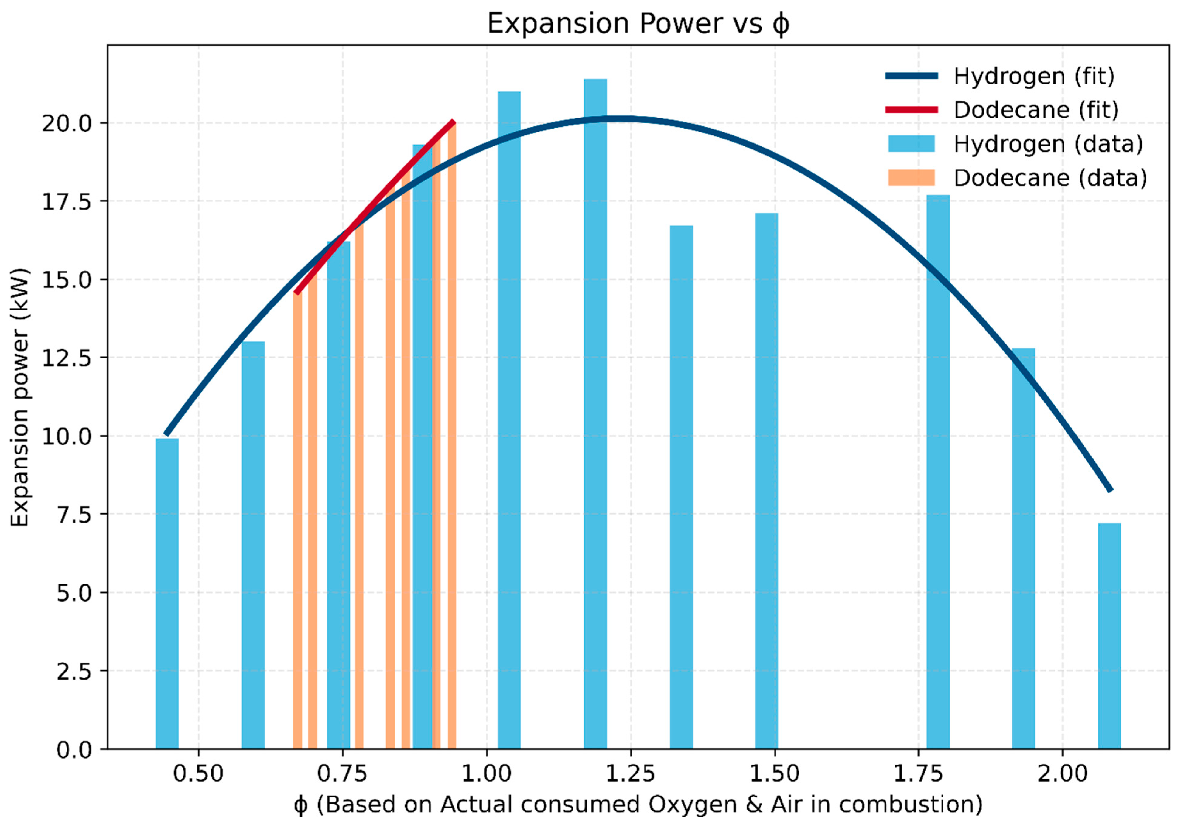
Figure 4.
Efficiency vs Equivalence Ratio (ϕ) for Hydrogen and Dodecane.
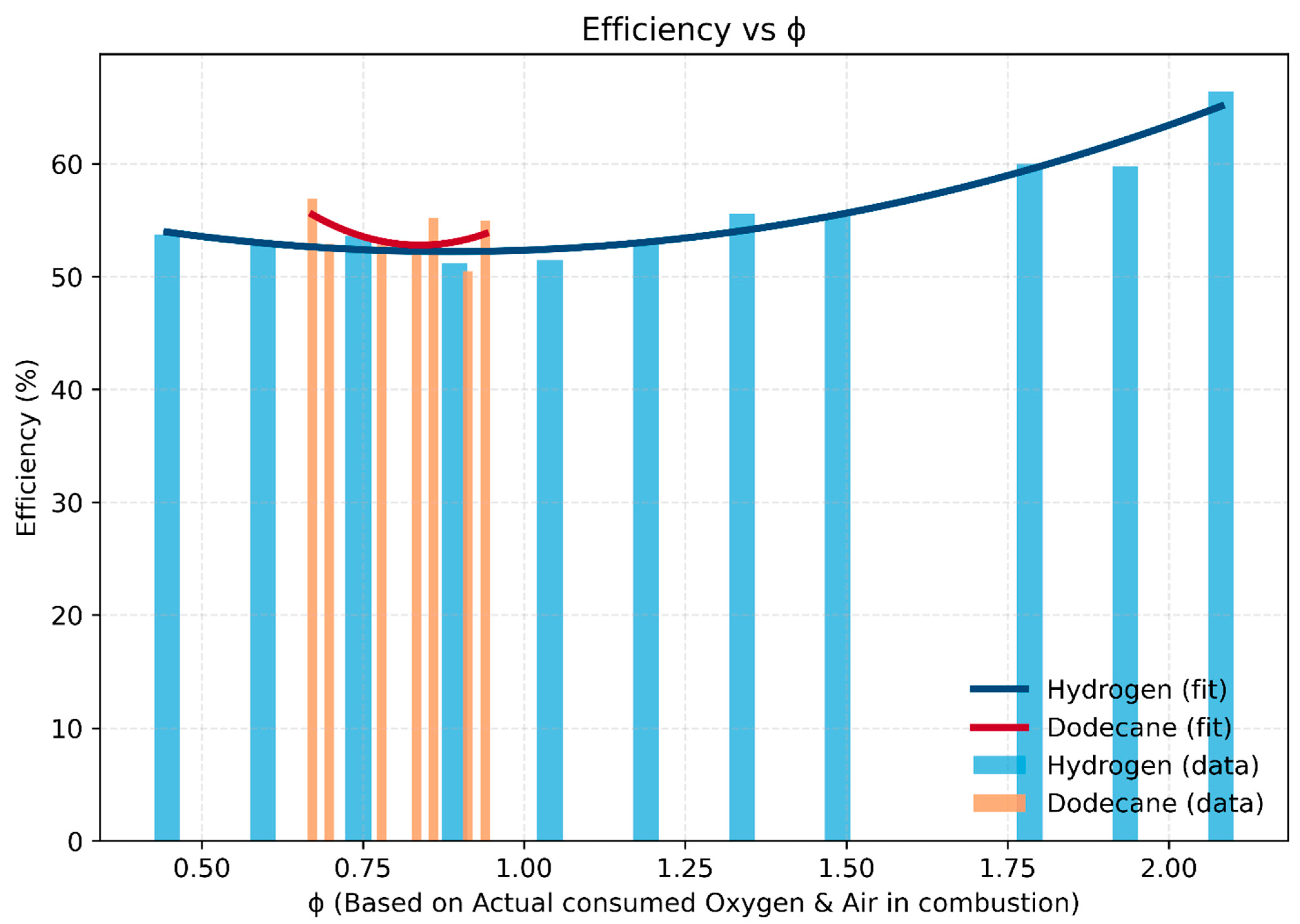
Figure 5.
Efficiency vs. Intake Temperature at Different Compression Ratios.
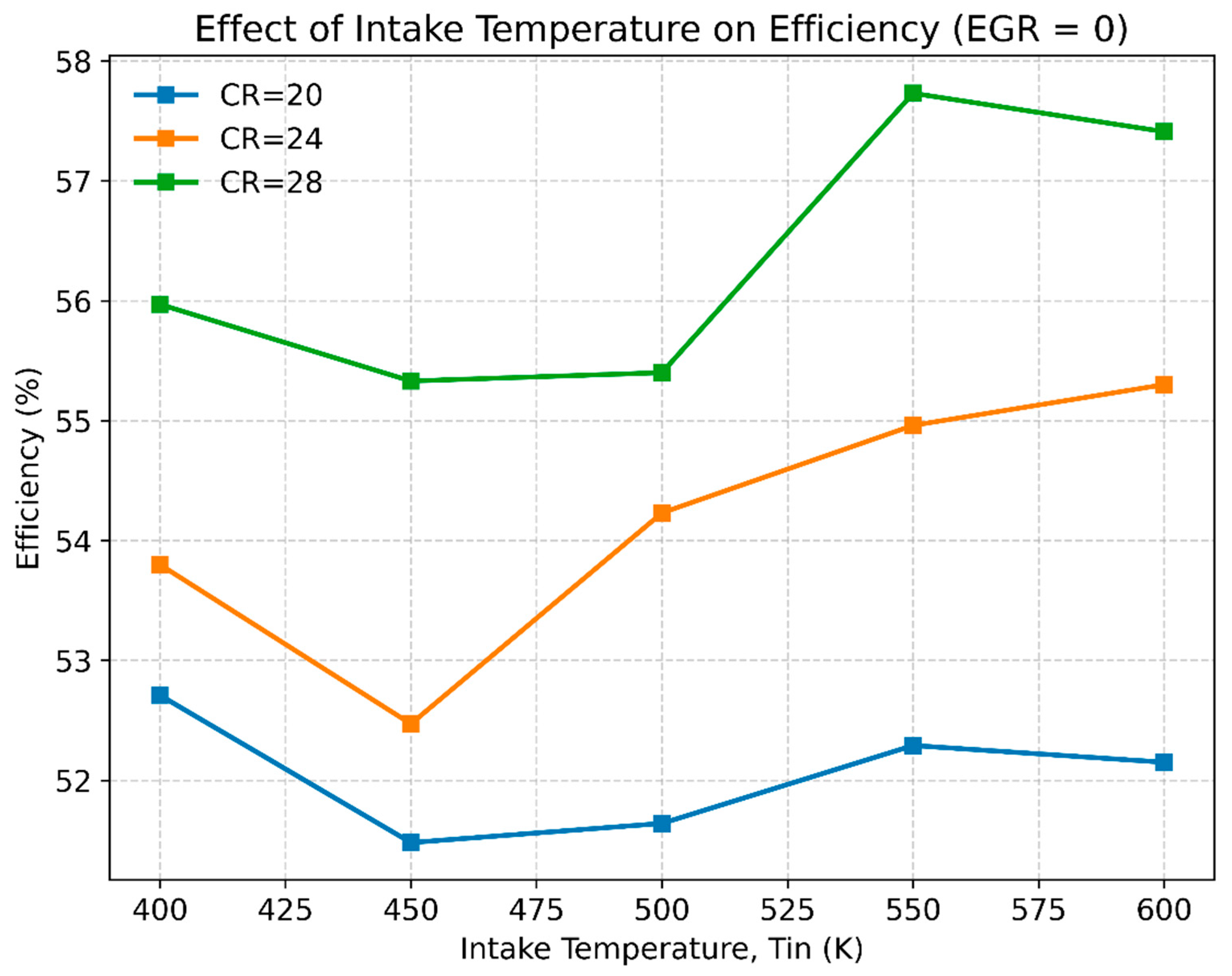
Figure 6.
Effect of Compression Ratio and Intake Temperature on Expansion Power.
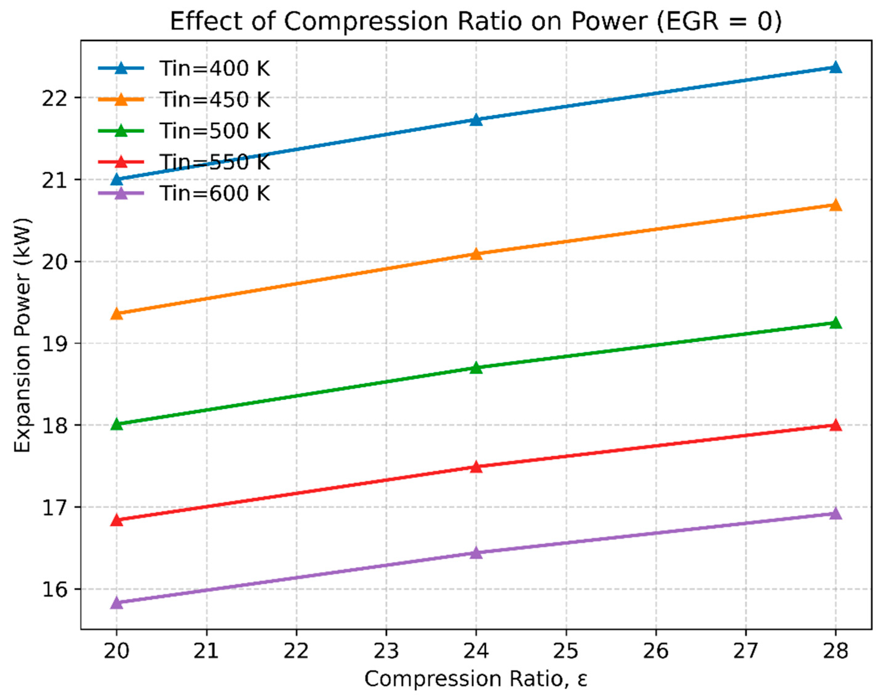
Figure 7.
Effect of EGR on unburned hydrogen slip at different intake temperatures.

Figure 8.
Effect of EGR on NOx emissions at different intake temperatures.
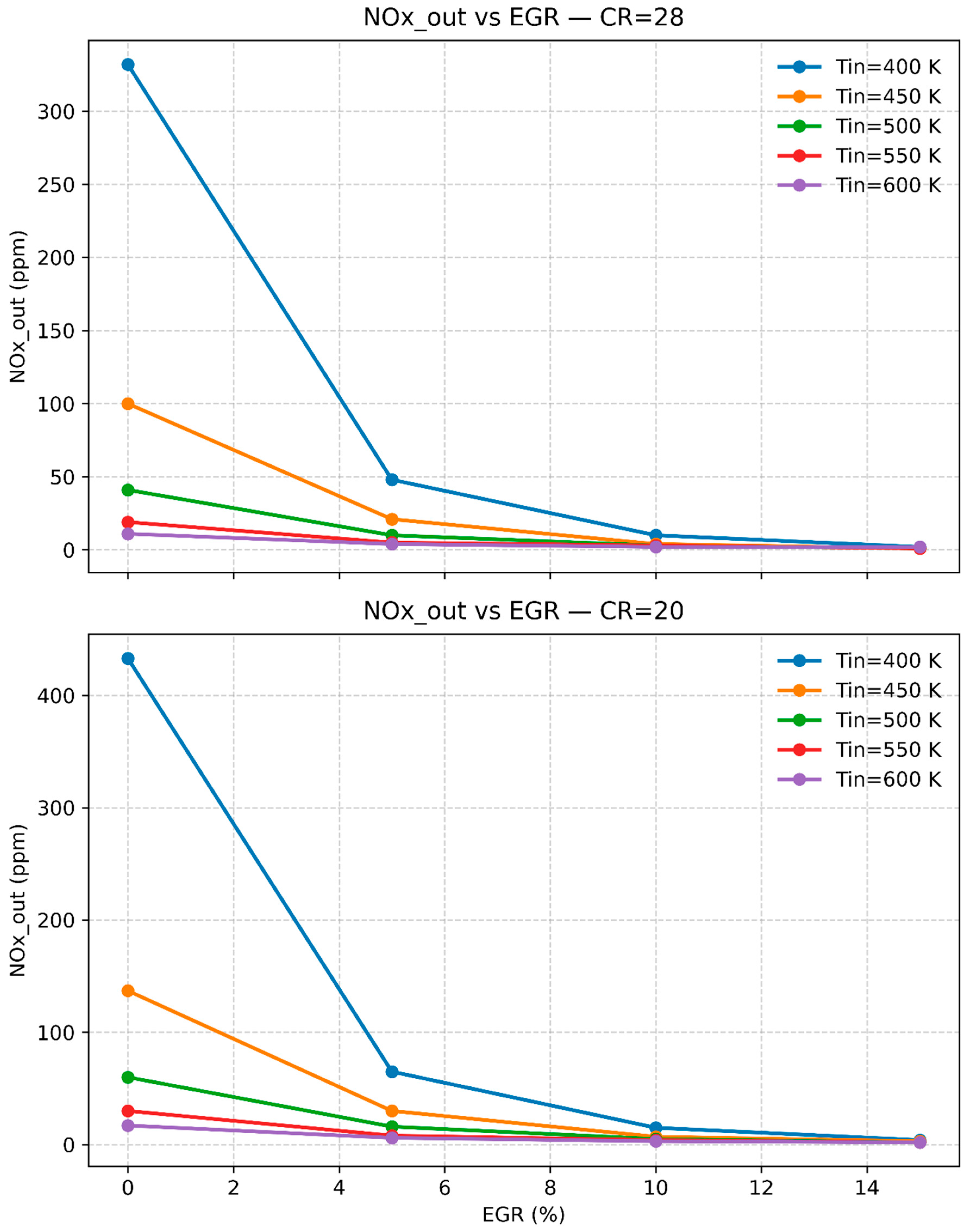
Figure 9.
Effect of EGR on engine power at different intake temperatures.
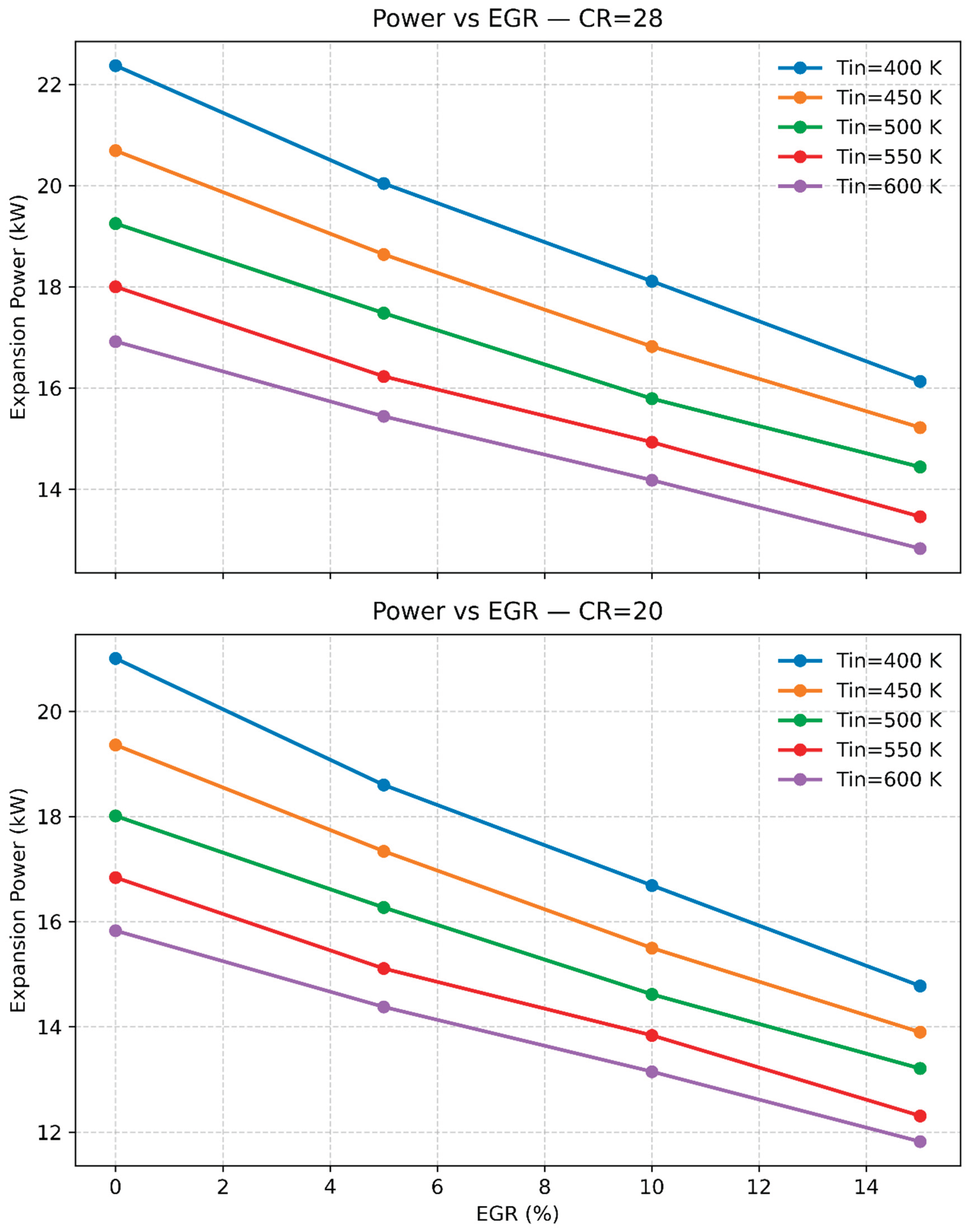
Table 1.
Key Research on Compression Ignition (CI) Functionality Utilizing hydrogen Fuel.
| Research/Strategy | Year | Compression Ratio (CR) | Key Findings | Challenges/Limitations |
| Helmore and Stokes | 1930 | 11.6 | Attempted CI operation with hydrogen. Observed misfiring and violent detonation.[2] | hydrogen’s characteristics make it challenging to ignite solely through compression. |
| Homan et al. (Glow Plug Assistance) | 1979 | 29 | Glow plugs provided stable ignition, higher IMEP than diesel, and knock-free combustion.[14] | Continuous glow plug use led to efficiency losses due to thermal demands. |
| Ikegami et al. | 1982 | 18.6 | Claimed successful hydrogen CI operation; later contested—possible ignition due to contaminants.[11] | Ignition reliability was limited without pilot fuel or hot spots. |
| Rosati and Aleiferis | 2000 | 17.5 | Achieved hydrogen ignition at 200-400°C intake with ultra-lean mixtures [12] | Elevated intake temperatures increased NOx emissions and energy use. |
| Lee et al. | 2013 | >26 | Demonstrated possible hydrogen CI with CRs as high as 26-32[13] | Narrow operating range with risk of knocking and backfire at high CRs. |
Table 3.
Optimal operating points for hydrogen engine (target: high power, low H₂ slip, and NOx reduction).
Table 3.
Optimal operating points for hydrogen engine (target: high power, low H₂ slip, and NOx reduction).
| Case | Tin (K) | CR | EGR (%) | Power (kW) | η (%) | Nox out (ppm) | H₂ out (mf) | Rationale |
| 1 | 400 | 28 | 5 | 20.04 | 55.7 | 48 | 0.07 | Highest power with minimal hydrogen slip; moderate NOx reduction. |
| 2 | 400 | 28 | 10 | 18.11 | 57.24 | 10 | 0.11 | Balanced compromise: large NOx reduction with acceptable power penalty. |
| 3 | 400 | 28 | 15 | 16.13 | 58.95 | 2 | 0.15 | Ultra-low NOx regime; significant power penalty and higher hydrogen slip. |
| 4 | 450 | 28 | 5 | 18.64 | 57.25 | 21 | 0.1 | High efficiency with moderate NOx control; power slightly lower than Case 1. |
| 5 | 450 | 28 | 10 | 16.82 | 58.2 | 4 | 0.14 | Strong NOx reduction with reasonable efficiency; reduced power. |
| 6 | 400 | 24 | 5 | 19.35 | 53.79 | 55 | 0.07 | Power-oriented option under moderate compression ratio constraints. |
| 7 | 400 | 24 | 10 | 17.41 | 55.94 | 12 | 0.11 | Balanced choice for CR = 24 with significant NOx reduction. |
Disclaimer/Publisher’s Note: The statements, opinions and data contained in all publications are solely those of the individual author(s) and contributor(s) and not of MDPI and/or the editor(s). MDPI and/or the editor(s) disclaim responsibility for any injury to people or property resulting from any ideas, methods, instructions or products referred to in the content. |
© 2025 by the authors. Licensee MDPI, Basel, Switzerland. This article is an open access article distributed under the terms and conditions of the Creative Commons Attribution (CC BY) license (http://creativecommons.org/licenses/by/4.0/).
Copyright: This open access article is published under a Creative Commons CC BY 4.0 license, which permit the free download, distribution, and reuse, provided that the author and preprint are cited in any reuse.


