
Submitted:
22 September 2025
Posted:
22 September 2025
You are already at the latest version
Abstract
With the growing interest in fabricating nanofiltration membranes using novel materials and techniques, there is an increasing need to evaluate the practical viability of innovative membranes at the early stages of development. In many materials research laboratories, the access to professionally manufactured membrane evaluation systems may be limited. Here, we present a pressure driven filtration system design for evaluation of nanofiltration membranes, that can be constructed from 3D-printed parts and widely available off-the-shelf components at a cost of approximately 60 €. The system uses a stirred cross-flow design capable of circulating the feed solution at the membrane surface and maintaining a stable feed concentration over extended filtration experiments—like conventional cross flow cells. It is suitable for filtration of aqueous solutions containing dyes, inorganic salts and dilute acids. Validation was performed by filtering a 2000 mg L−1MgSO4 solution through a Veolia RL membrane at 7.6 bar, achieving a 96.5% rejection rate and a permeance of 7.5 L m−2 h−1 bar−1 after 24 hours of continuous operation.
Keywords:
pressure-driven membrane filtration
; membrane evaluation
; nanofiltration
; 3D printing
; hardware
; low cost
1. Introduction
Membrane nanofiltration (NF) is a well established technology used in various industries including water treatment, pharmaceutical, and food production. Over the past decade, there has been growing interest in using of novel materials and fabrication techniques for NF membranes [1]. In parallel with this trend, the need to evaluate the practical viability of innovative membranes has become increasingly critical at early stages of development. While a wide range of microscopy, spectroscopy and physical characterization techniques are routinely employed to assess chemical structure, membrane morphology, pore size, hydrophilicity, and zeta potential, etc. Perhaps the most essential characterization technique is practical filtration evaluation [2]. Pressure driven filtration evaluation can be performed in either a dead-end or a cross-flow setup. Dead-end setups are relatively simple, typically consisting of a pressure regulated gas line connected to a reservoir that supplies a cell holding the filter with feed solution at a constant pressure. The drawback of a dead-end setup is that rejected species accumulate at the membrane surface during filtration, leading to reduced permeance and apparent rejection rates. Therefore, a setup that circulates the solution at the membrane surface is needed for reliable evaluation. This is accomplished in either a stirred dead-end or a cross-flow setup. Stirred dead-end systems incorporate a stirred reservoir in the filter cell, while cross-flow setups employ a pump to continuously circulate the feed solution across the membrane surface. In stirred dead-end systems, the feed concentration increases over time with removal of permeate. Therefore, cross-flow setups are preferable for longer duration experiments as they can run continuously at steady-state conditions. Conducting extended filtration experiments (lasting at least several hours) is essential for system equilibration and accurate assessment of long-term membrane performance under realistic conditions
Commercial membrane evaluation systems are expensive, with stirred dead-end cells typically costing over 2000 € and cross-flow setups being several times more expensive. They are usually designed for membrane sizes of at least 15 c which may be impractical for evaluating membranes at early stages of development, when only limited material is available. Here, we present a filtration system design that can be constructed using accessible tools and low cost materials. The system operates without a pump, but is capable of running continuously at steady-state conditions similarly to a conventional cross-flow setup. The system has been successfully tested operating at 7.6 bars and is suitable for filtration of dilute aqueous solutions of dyes, acids, inorganic salts, etc. The filter cell designs can be adapted to accommodate circular membranes with diameters of 30 mm or smaller.
2. Design
2.1. Overview
Our system is constructed from low-cost widely available components and parts that can be printed on a simple desktop fused deposition modeling (FDM) 3D-printer. Since 3D-printing a conventional stirred dead-end cell with an integrated high-volume feed reservoir capable of withstanding high pressure is challenging, the system instead utilizes a separate feed reservoir and a compact filter cell. The cell is available in two variants: dead-end and stirred cross-flow. The stirred cross-flow cell employs a magnetic stirring bar to circulate the solution in the cell and a retentate outlet to slowly flush the cell with fresh feed solution. This design enables continuous operation at a constant feed concentration similar to a conventional cross-flow system, without requiring a pump. The cross-flow system includes a regulator valve that is used to restrict the retentate flow. The system is assembled using 6 mm outer diameter pneumatic tubing (rated at 10 bar) and push-to-connect fittings for rapid assembly and component replacement. The feed reservoir is pressurized by a regulated pressure N2 source which drives the feed solution into the filter cell.
2.2. Filament Selection
Polyethylene terephthalate glycol (PETG) filament was used for the 3D-printed parts because it is readily available, can be printed on practically any desktop 3D printer—requiring extruder temperatures of only 220–240 °C— and a high print quality is achievable without a heated enclosure. It generally provides higher chemical resistance than other common filaments like Polylactic acid (PLA) and Acrylonitrile butadiene styrene (ABS) and is available free from additives, reducing the likelihood of contamination by compounds leeching from the plastic. The PETG parts that contain pressurized fluid were subjected to a heat-treatment post-processing step [3,4] to eliminate voids between print lines and ensure fluid could not seep through the bulk of the parts. Although filaments such as polyethylene (PE), polypropylene (PP), and polyvinylidene fluoride (PVDF) offer greater chemical resistance and are compatible with standard desktop 3D printers, their low stiffness makes designing a pressure-tight filter cell more challenging. An alternative filter cell design that is pressure-tight when printed in PP is presented in Appendix A.
2.3. Filter Cell
The filter cell is available in two variants: dead-end and stirred cross-flow Figure 1. It consists of a top and a bottom housing that are held together by a KF-25 ring-clamp. The clamp is tightened with a single wingnut allowing rapid replacement of the membrane. A ring in the top housing and groove in the bottom housing center the two halves of the cell when they are assembled. The membrane is placed on a grid in the bottom housing which collects the permeate into an outlet channel. The dead-end cell features a fitting for connecting the feed inlet tube in its top housing and a permeate outlet nozzle in its bottom housing. The cross-flow cell has an additional retentate outlet tube connection in its top housing. A stirring bar retained by a stainless steel wire is suspended from a beam that is press fit into a socket in the top of the cell so that the bar can rotate freely without contacting the membrane. The cross-flow cell uses a tube for its permeate outlet as the cell needs to sit on a magnetic stirring plate.
2.4. Feed Reservoir
The feed reservoir is constructed from a plastic water-carbonation bottle and a custom-built cap (Figure 2A). A plug with connections for a pressure inlet and liquid outlet, seals to the neck of the bottle using an O-ring. A retaining ring threaded onto the bottle, holds the plug in place. The cap is designed to fit a standard 1 L SodaStream bottle. While the bottles lack an official pressure rating, they must to withstand pressures of several bars in their intended use case and are designed with generous safety margins. The bottles are typically produced from polyester or polyester copolymers and are therefore resistant to dilute acids and inorganic salt solutions [5].
2.5. Regulator Valve
The regulator valve attaches to the retentate tube and utilizes an M4 bolt threaded into a 3D-printed part to create a narrow channel (Figure 2B). The flow rate can be adjusted by turning the bolt. The bolt head is fitted with a handle to assist hand turning.
2.6. Other Accessories
An outlet tube holder and a cuvette stand were designed for use with the filtration system. While these are not necessary for operation, they are helpful for collecting series of small permeate fractions during filtration experiments. The outlet tube holder can be taped to a bench for stability and has a hole through which the end of the outlet tube is threaded. The cuvette stand holds ten cuvettes and is placed at the permeate outlet. These parts were designed for ease of printing and can be printed without supports from PLA filament.
3. Build Instructions
Table 1 lists the materials required to construct the cross flow setup. Appendix B lists the required tools. The 3D model files are provided in the supporting information. Comprehensive descriptions of the model files are available in Appendix C.
3.1. Printing and Heat-Treating
The parts should be printed with 100% infill and the supports should be removed. The parts that will contain pressurized liquid (feed reservoir cap plug, filter cell top housing, and regulator valve) must then be heat-treated to eliminate voids between the printing lines. To heat-treat the parts they should be packed in a sodium chloride salt bed, heated at 180 °C for 40 minutes in a convection oven, cooled to room temperature, removed from the salt bed and rinsed in water. Use a fine salt powder and thoroughly fill all voids around the parts. The fine salt powder can be prepared by pulverizing table salt in a kitchen blender. The temperature and heating time may need adjustment depending on the salt bed volume, filament brand, etc. The parts should retain their original dimensions after heating. If significant sink marks or surface pitting appear, it indicates excessive voids in the printed parts. This can be resolved by using well dried filament and possibly raising the extrusion multiplier in the slicer. A “test piece” model that can be printed quickly and used to optimize print settings and heat-treatment parameters is available in the supporting information. The test piece can be pressurized through a push-to-connect fitting and submerged in water to check for leaks. After heat-treatment, the grid surface in the filter cell bottom housing and the O-ring grooves in the top housing should be wet polished with sand paper to ensure proper sealing.
3.2. Fitting Installation
- To install push-to-connect fittings in the printed parts, threads are first partially cut using a tap. The fitting is then screwed in to complete the thread shaping, removed, wrapped with polytetrafluoreten (PTFE) sealing tape and reinstalled.
- The O-ring and retaining ring of the feed reservoir cap need to be installed around the plug before the fittings are inserted. A tube of appropriate length, sufficient to reach the bottom of the reservoir is then inserted into the bottom fitting of the plug.
- The bolt hole in the pressure regulator valve is threaded using an M4 tap. However, the full depth of the hole should not be threaded to allow complete closure of the valve by fully tightening the bolt.
- To install the permeate outlet tube in the cross-flow cell, the hole is threaded using an M5 tap. The tube is fastened using a standard finger-tight, high-pressure liquid chromatography (HPLC) column connector screw. PTFE sealing tape can be applied around the cone-shaped end of the screw if needed for a tight seal.
3.3. Stirring bar Installation
Images to complement the step-by-step instructions are shown in Figure 3.
- A 0.8 mm thick stainless steel wire is wrapped around the center of the stirring bar and twisted to secure it firmly. The twisted part should be no longer than ∼3 mm. One end of the wire is trimmed, while the other is shaped into the shaft around which the bar will rotate. The shaft should be as straight as possible, oriented perpendicular to the bar, and aligned with its center.
- The hole in the printed beam is drilled out to the shaft’s dimensions. The shaft is then inserted through the beam. It should be able to rotate with minimal resistance. A piece of 0.5 mm thick PTFE sheet serving as a bushing is then threaded onto the shaft and trimmed to the dimensions of the circular central part of the beam.
- A short piece of wire, serving as a shaft collar, is bent into a U-shape around the end of the shaft. A bench vise is used to press the collar firmly onto the shaft so that the stirring bar is retained ∼5 mm from the beam. The shaft is then cut above the collar.
- The beam is pressed into the socket in the top housing of the cell, suspending the stirring bar in the chamber so that it does not contact the membrane when the cell is closed. The ends of the stirring bar can be trimmed with a knife if they interfere with free rotation.
4. Operating Instructions
Precautionary statement: Be aware that the filtration system operates using pressurized gas. Improper operation or component failiure could result in serious injury. During testing, our system it was pressurized at 7.6 bar for 24 hours without failure or noticeable leakage. However, this does not guarantee that a system constructed according to the provided instructions will be safe to operate at these pressures. The authors take no responsibility for injuries sustained when operating the filtration system. To minimize accident risk, observe the following precautions:
- Ensure that all components are sealed and connected securely before pressurizing the system.
- Ensure that the system is completely depressurized before disconnecting or opening any components.
- When pressurizing, raise the pressure slowly while monitoring for leaks.
- Take care not to damage or weaken any components mechanically or by exposure to chemicals, extreme temperatures, or strong ultraviolet light.
- Take appropriate precautions to avoid injury in case of an explosion or the leakage of liquid or gas. If a hazardous feed solution is used place the setup in a fume hood. If high operating pressure is used, keep the system behind a safety shield when pressurized.
4.1. Membrane Installation
The filter cell is assembled as shown in Figure 4B. The inner O-ring seals the top housing of the cell against the membrane and the outer O-ring seals the gap between the housing pieces. The ring clamp is installed around the rim of the cell, and the wingnut tightened to clamp the halves together. A piece of filter paper should be placed underneath the membrane as a support. When installing a fragile membrane, place a gasket between the inner O-ring and the membrane to protect it from tearing as the O-ring deforms under clamping. The gasket can be cut from a polymer sheet. We used a 0.5 mm thick PTFE sheet, but other of soft polymer sheets such as PE or PP, can also be used. If a gasket is used in the cross-flow cell, ensure that inner diameter of the gasket is large enough so that its inner edge is pressed firmly against the membrane by the O-ring. Otherwise there will be a region underneath the gasket where the feed solution will infiltrate, but where it is not circulated.
4.2. System Assembly
Connect the components as shown in Figure 4A. If a cross-flow setup is used, connect the retentate outlet of the cell to the flow regulator valve. The system is pressurized by closing the release valve and then opening the fill valve. Any air present in the feed tube and filter cell must be evacuated before starting the filtration. In the cross-flow system this is done by pressurizing the system and maintaining a high retentate flow until all air has escaped through the retentate stream. In the dead-end system, close the release valve, then fill feed tube and filter cell with feed solution using a pipette before connecting the cell.
5. Validation
A Veolia RL thin film composite polyamide flat sheet membrane was evaluated using our stirred cross-flow setup. A circular piece of membrane with a diameter of 29.5 mm was used. The diameter of the active membrane area was estimated as the inner diameter of the inner O-ring (23.5 mm). Standard evaluation parameters were followed as closely as possible [6]. An aqueous 2000 mg MgSO4 solution was filtered at 7.6 bar operating pressure for 24 hours. The operating temperature was 23 °C, close to the standard 25 °C. Several feed reservoirs were connected in series to provide enough feed solution for the full experiment. The permeate recovery rate is ideally maintained at 15%, but as the flow through the regulator valve tends to decrease over time—requiring constant monitoring to maintain—it fluctuated between 5% and 55% during the experiment. During portions of the experiment, permeate fractions were collected at 6 minute intervals while the retentate flow rate was continuously monitored and adjusted. For the majority of the experiment, however, the system was unsupervised, with permeate and retentate collected in a large containers during these periods. The conductivity of the permeate was measured using an eDAQ ET915 conductivity electrode and the concentration was determined using a standard curve. The results are shown in Figure 5. After 24 hours the rejection rate was 96.5% and the permeance was 7.5 L ba. The permeance is within the expected range specified by the manufacturer for spiral wound RL-membranes (5.3-8.7 L ba depending on model), but the rejection rate is lower than the expected 99.5%. The lower rejection rate is likely due to somewhat less efficient circulation of the feed solution than in a conventional cross-flow setup, however it could also be related to the fluctuating permeate recovery rate. The setup was also evaluated using the same membrane and operating pressure, but filtering a 10 mg Congo red dye solution for 2 hours. In this case the rejection rate reached ∼100% by the end of the experiment.
6. Conclusions
We have developed a low-cost nanofiltration (NF) membrane evaluation system that can be assembled using accessible tools and materials. Designed for membranes with small dimensions, the system provides an affordable and practical solution for assessing membrane performance during the early stages of development. Validation experiments using a commercial NF membrane demonstrated rejection rates approaching those specified by the manufacturer, confirming the system’s viability. Minor deviations are likely attributed to insufficient stirring or fluctuations in the retentate flow rate. These limitations could be addressed by implementing a more precise flow control mechanism, such as a high-precision needle valve or a back-pressure regulator. Circulation within the filter cell could also be improved by using a plate stirrer with stronger magnets, optimizing the cell design by increasing the distance between feed and retentate ports, or raising the retentate flow rate.
While the system successfully operated at 7.6 bar for 24 hours during validation, without leakage or component failure, the maximum safe operating pressure remains uncertain due to the use of non-rated components. Neither the feed reservoir, constructed from a repurposed carbonation bottle, nor the filter cell, fabricated from 3D-printed parts, has been thoroughly tested for durability or failure pressure. Therefore, the system should be kept behind a safety shield when operated at pressures above a few bars. Further raising the maximum operating pressure significantly beyond the 7.6 bar applied during validation would require a major redesign of the system. The tubing and fittings (currently rated at 10 bar) would need to be replaced with stronger alternatives, as would the feed reservoir. Additionally, the filter cell would likely need stiffening through reinforcing with thicker material, necessitating a redesign of the clamping mechanism.
Adapting the system to be compatible with a wide range of organic solvents would significantly expand its applicability, as organic solvent nanofiltration is an emerging area of membrane research [7]. A dead-end filter cell printable in PP filament is presented in Appendix A, offering a more chemically resistant alternative. However, to ensure full system compatibility, practically every component would need to be replaced. Nitrile O-rings could be replaced with fluoroelastomer (e.g., Viton) alternatives, and the feed reservoir could either be replaced with a commercial pressure vessel or the current design adapted to use a stainless steel bottle with sufficient strength and a cap plug printed from PP. Although several chemically resistant tubing and fittings options are available, finding an alternative that is low-cost, high-pressure compatible, and easy to integrate with 3D-printed parts remains a challenge.
Overall, this system provides a flexible and accessible platform for membrane evaluation in laboratory environments with limited resources, while offering several paths for future improvement and adaptation.
Supplementary Materials
The following supporting information can be downloaded at: Preprints.org
Author Contributions
Conceptualization, K.E.; methodology, K.E.; validation, K.E.; investigation, K.E.; resources, K.E.; data curation, K.E.; writing—original draft preparation, K.E.; writing—review and editing, K.E., C.X., M.S.; visualization, K.E.; supervision, C.X.; funding acquisition, M.S. All authors have read and agreed to the published version of the manuscript.
Funding
The authors acknowledge the financial support provided by the Knut and Alice Wallenberg Foundation.
Data Availability Statement
Dataset available on request from the authors.
Conflicts of Interest
The authors declare no conflicts of interest.
Appendix A. Polypropylene Filter Cell
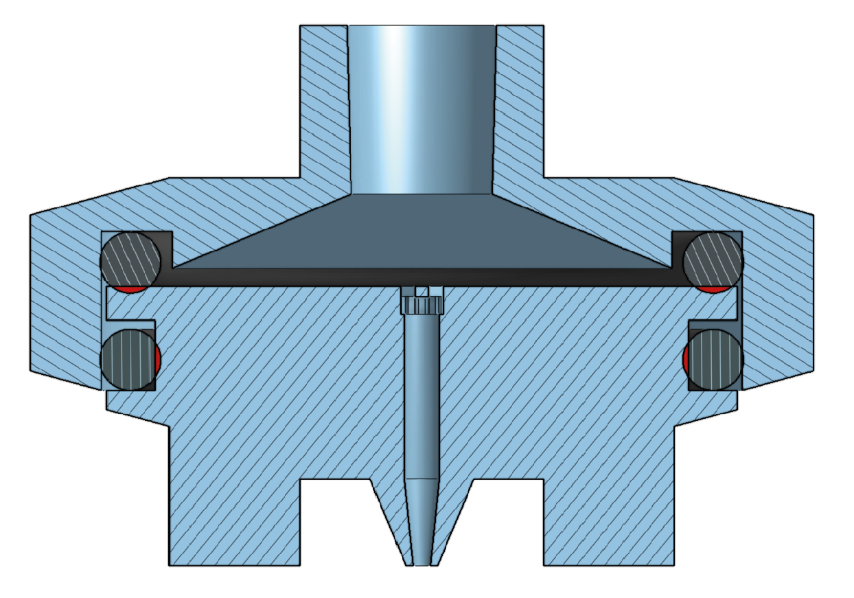
We were unable to achieve reliable sealing with a polypropylene filter cell design employing two face-sealing O-rings. Due to the inherent flexibility of polypropylene filament, the cell deforms under clamping pressure, and if the inner O-ring diameter is too small, it is not compressed sufficiently to form an effective seal. By using a radially sealing outer O-ring the diameter of the inner O-ring can be increased so that it is compressed enough by the clamp to seal effectively. This design (Figure A1) was printed using Fiberology PP filament and pressurized at 8 bar without leakage, however it has not been validated through practical usage. Owing to the excellent chemical resistance of polypropylene, the cell could be used for filtration of most organic solvents and in highly acidic or basic conditions. However, for this to be viable, the chemical resistance of all of the filtration system’s components would have to be ensured. An additional advantage of using PP filament is that the printed parts were leakproof without requiring an additional heat-treatment step.
Figure A1.
Cross section of filter cell design that can be printed in polypropylene.
Appendix B. Software and Tools Used
The 3D-printed components of the system were designed using the Onshape computer aided design (CAD) software. They were printed on a Prusa i3 MK3S printer with a standard 0.4 mm nozzle. Prusa slicer (version 2.9.2) was used for slicing. For printing PETG parts, standard 0.2 mm layer height, high quality print settings were used, except infill was set to 100% and supports were applied where needed. A Flux Beambox laser cutter and the Beam Studio software was used to cut membrane coupons, although this could also be done by hand. The following tools were also used: thread taps in sizes M4, M5, and 1/8" BSPT (a 1/8" NPT tap was used instead due to unavailability of a BSPT tap); 0.8 mm drill bit; bench vise; pliers; wire cutters; wrenches; sandpaper; and a utility knife.
Appendix C. Design Files
Appendix C.1. Onshape CAD Project
The filter cell model files provided in the supporting information are designed to use a 23.5x3.5 mm inner O-ring, a 34.5x3. mm outer O-ring and to hold a 29.5 mm diameter membrane where the combined thickness of the membrane, supporting layer and optional gasket is ∼0.1 mm. However, the dimensions of the designs can be modified within the Onshape CAD document using a set of named variables. A link to the online document is provided in the Supporting Information. The variables can be adjusted to accommodate different gasket and O-ring sizes, membrane diameters, and to account for dimensional variability in the ring clamp. The named variables include:
- #Cell_OD, #Edge_height - Diameter and height of cell outer rim at target compression (assuming parts are rigid). Adjust to account for differences in ring clamp dimensions
- #Stack_height - Combined thickness of gasket, membrane, and support. Adjust to account for different thicknesses.
- #Centering_ring_clearance - Clearance between centering ring and groove. Adjust if required for tight fit.
- #IOR_ID, #IOR_thickness, #IOR_compression - Inner diameter, thickness, and target compression ratio of inner O-ring. The inner O-ring dimensions determine the diameter of membrane that can be fitted.
- #OOR_ID, #OOR_thickness, #OOR_compression - Inner diameter, thickness, and target compression ratio of outer O-ring. The compression ratio for the outer O-ring should be lower than for the inner O-ring. This is to ensure that the inner ring which needs to contain high pressure seals tightly even if the cell deforms slightly under clamping.
Appendix C.2. Model Files
The following “.stl” 3D model files are available in the supporting information. The list specifies if they require supports or heat-treatment post-processing. The models should be printed using PETG filament with 100% infill unless otherwise specified. The filter cell parts should be printed with the sealing surfaces facing up.
-
Cap plug Supports Required, Heating Required
- Plug for the feed reservoir cap.
-
Cap ring No Supports, No Heating
- Threaded ring for the feed reservoir cap.
-
CF beam No Supports, No Heating
- Beam for suspending the stirring bar in the cross-flow cell.
-
CF bottom housing Supports Required, No Heating
- Bottom housing of the cross-flow cell.
-
CF top housing Supports Required, Heating Required
- Top housing of the cross-flow cell.
-
DE bottom housing Supports Required, No Heating
- Bottom housing of the dead-end cell.
-
DE top housing Supports Required, Heating Required
- Top housing of the dead-end cell.
-
Regulator handle No Supports, No Heating
- Handle for for the bolt in the regulator valve.
-
Regulator valve No Supports, Heating Required
- Housing for the regulator valve. A solid bridging layer has been added to the central channel to enable printing without supports. The bridging layer should be cut out when printed.
-
Test piece No Supports, Heating Required
- A test piece that is quick to print and can be used to validate print settings and heat treatment procedure. It is a simple vessel with a connection for a push-to-connect fitting.
-
Outlet tube holder PLA filament, No Supports, No Heating
- Holder for the end of the outlet tube. Printed using PLA with 20% infill.
-
Cuvette stand PLA filament, No Supports, No Heating
- Cuvette stand for collection of permeate fractions. Printed using PLA with 20% infill.
-
PP bottom housing PP filament, Supports Required, No Heating
- Bottom housing of the polypropylene filter cell.
-
PP top housing PP filament, Supports Required, No Heating
- Top housing of the polypropylene filter cell.
References
- Mallakpour, S.; Azadi, E. Novel methodologies and materials for facile fabrication of nanofiltration membranes, 2022. [CrossRef]
- Agboola, O.; Maree, J.; Mbaya, R. Characterization and performance of nanofiltration membranes. Environmental Chemistry Letters 2014, 12, 241–255. [Google Scholar] [CrossRef]
- Youtube user "free spirit 1". Remelting 3D printed thermoplastics (the salt method). https://www.youtube.com/watch?v=nRLJ4ylGTFc, 2020.
- Zapciu, A.; Amza, C.G.; Baciu, F.; Vasile, M.I. Heat treatment of 3D printed polyethylene terephthalate glycol in a supporting powder bed. IOP Conference Series: Materials Science and Engineering 2021, 1182, 012083. [Google Scholar] [CrossRef]
- Woishnis, W.; Ebnesajjad, S. Chemical resistance of thermoplastics; PDL handbook series; Elsevier: Waltham, Mass, 2012; pp. 2558–2660. [Google Scholar]
- Morgante, C.; Lopez, J.; Cortina, J.L.; Tamburini, A. New generation of commercial nanofiltration membranes for seawater/brine mining: Experimental evaluation and modelling of membrane selectivity for major and trace elements. Separation and Purification Technology 2024, 340. [Google Scholar] [CrossRef]
- Waheed, A.; Sajid, M.; Baig, U.; Jillani, S.M.S.; Younas, H.; Ahmad, H.; Aljundi, I.H. Role of covalent crosslinking and 2D nanomaterials in the fabrication of advanced organic solvent nanofiltration membranes: A review of fabrication strategies, recent advances, and challenges. Separation and Purification Technology 2025, 353. [Google Scholar] [CrossRef]
Figure 1.
Cross section exploded views of: (A) Dead-end cell, and (B) Cross-flow cell with components labeled.
Figure 1.
Cross section exploded views of: (A) Dead-end cell, and (B) Cross-flow cell with components labeled.
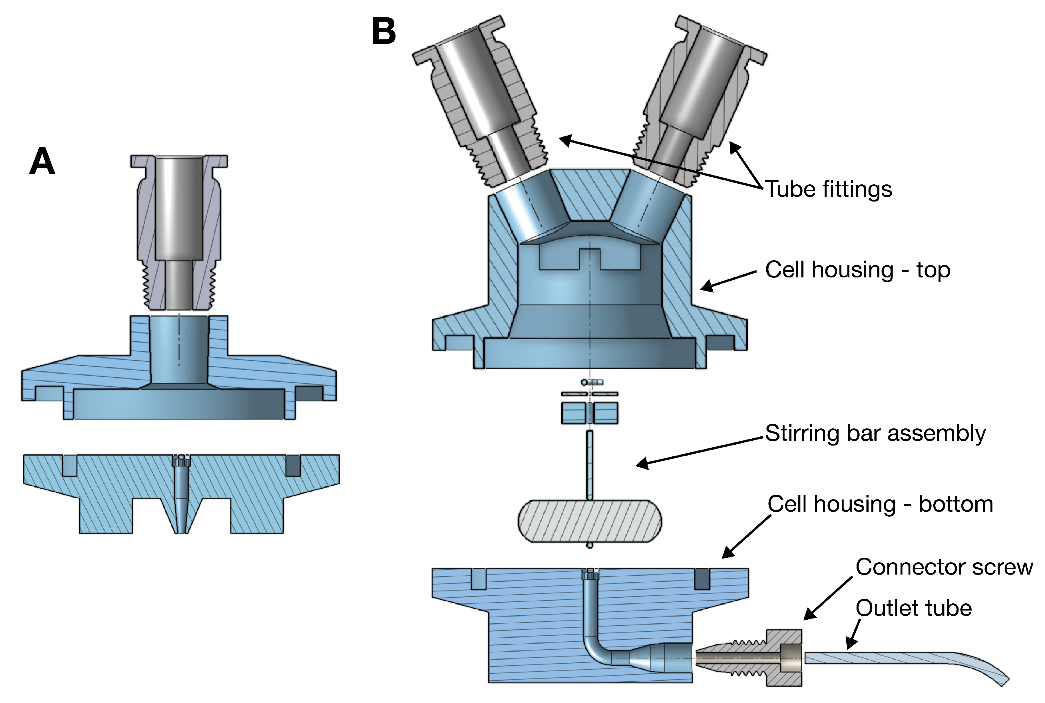
Figure 2.
Cross section exploded views of: (A) Feed reservoir cap, and (B) Flow regulator valve.
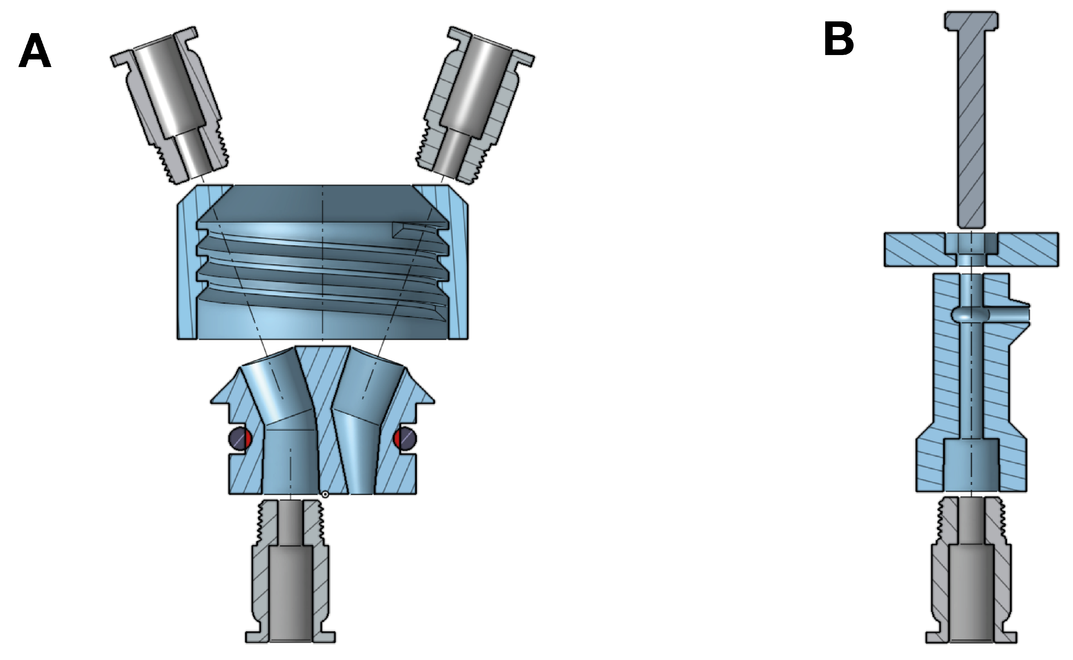
Figure 3.
Images showing steps 1-4 of the stirring bar installation.

Figure 4.
(A) Tubing diagram for filtration system. (B) Cross sectional exploded view of filter cell assembly.
Figure 4.
(A) Tubing diagram for filtration system. (B) Cross sectional exploded view of filter cell assembly.
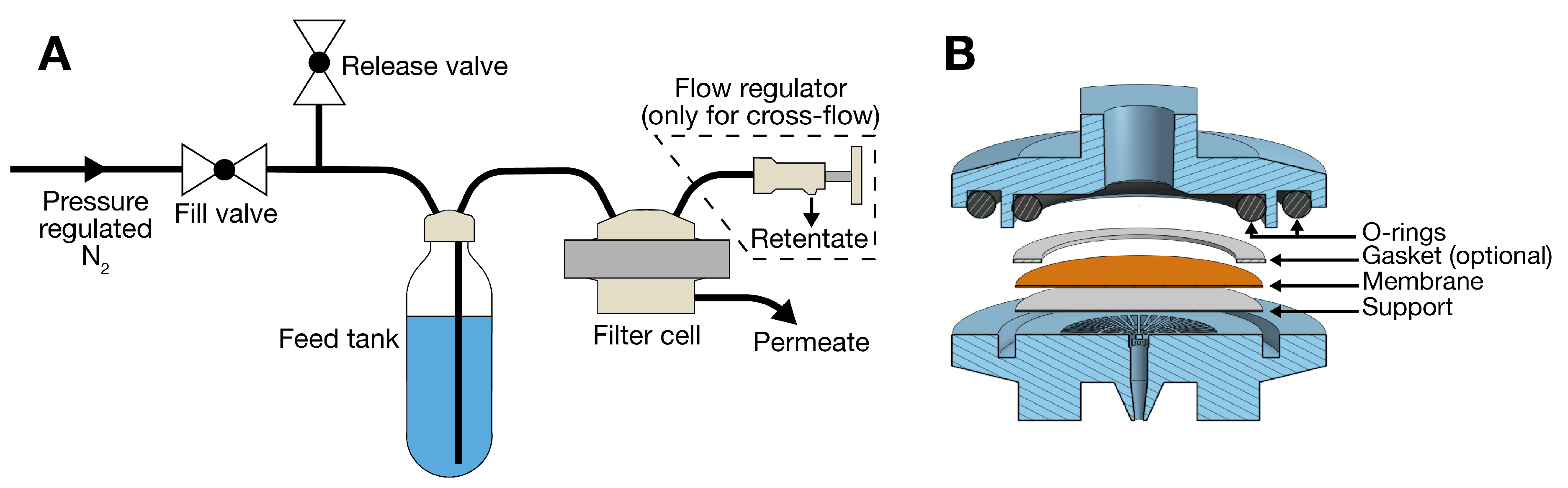
Figure 5.
(A) Plot of rejection, permeance, and permeate recovery rate over the 24 hour long filtration experiment. Points are plotted at the time at which collection of the corresponding permeate fraction ended. (B) Photo of permeate from the cross flow cell being collected in cuvettes.
Figure 5.
(A) Plot of rejection, permeance, and permeate recovery rate over the 24 hour long filtration experiment. Points are plotted at the time at which collection of the corresponding permeate fraction ended. (B) Photo of permeate from the cross flow cell being collected in cuvettes.
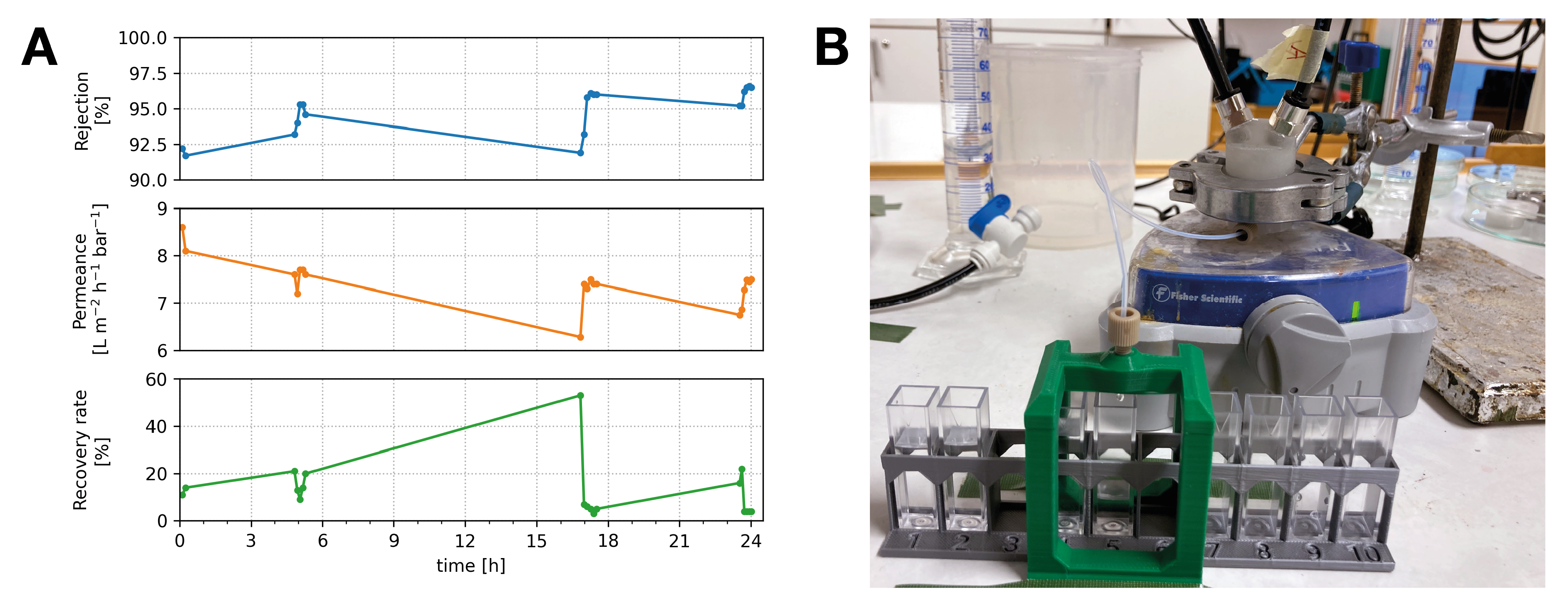

Table 1.
Bill of materials
| Item | Brand/Model | Quantity | Source | Cost [€] |
|---|---|---|---|---|
| Bolt | M4 x 30 mm, hex-head, full thread, stainless steel | 1 pcs | Amazon | 0.5 |
| Carbonation bottle | SodaStream, standard, 1 L | 1 pcs | Amazon | 7.5 |
| Chromatography tubing | PTFE, 1/16" OD | 15 cm | VWR | 1.95 |
| Connector screw | Finger tight column connector, 1/16" tube OD | 1 pcs | VWR | 12 |
| Filament (PETG) | Addnorth PETG clear | 81 g | Addnorth | 2.43 |
| Magnetic stirring bar | 20 x 6 mm, cylindrical, PTFE covered | 1 pcs | VWR | 0.7 |
| O-ring | 22 x 3.5 mm, nitrile | 1 pcs | Amazon | 0.5 |
| O-ring | 23.5 x 3.5 mm, nitrile | 1 pcs | Amazon | 0.5 |
| O-ring | 34.5 x 3.5 mm, nitrile | 1 pcs | Amazon | 0.5 |
| Pneumatic tubing | PUR, 6 mm OD | 2.5 m | Amazon | 2 |
| PTFE sheet | 0.5 mm | 1 c | Amazon | 0.02 |
| Ring clamp | KF-25 | 1 pcs | Amazon | 26.25 |
| Sealing tape | PTFE | 30 cm | Amazon | 0.09 |
| T-coupling | 6 mm push fit | 1 pcs | Amazon | 0.4 |
| Threaded fitting | 6 mm push-fit, 1/8" BSPT thread | 5 pcs | Amazon | 4.5 |
| Valve | 6 mm push fit | 3 pcs | Amazon | 1.8 |
| Wire | 0.8 mm, stainless steel | 10 cm | Amazon | 0.01 |
| Total cost | — | — | — | 61.65 |
Disclaimer/Publisher’s Note: The statements, opinions and data contained in all publications are solely those of the individual author(s) and contributor(s) and not of MDPI and/or the editor(s). MDPI and/or the editor(s) disclaim responsibility for any injury to people or property resulting from any ideas, methods, instructions or products referred to in the content. |
© 2025 by the authors. Licensee MDPI, Basel, Switzerland. This article is an open access article distributed under the terms and conditions of the Creative Commons Attribution (CC BY) license (http://creativecommons.org/licenses/by/4.0/).
Copyright: This open access article is published under a Creative Commons CC BY 4.0 license, which permit the free download, distribution, and reuse, provided that the author and preprint are cited in any reuse.


