
Submitted:
01 September 2025
Posted:
02 September 2025
You are already at the latest version
Abstract
Automated Driving Systems (ADSs) have the potential to make mobility services both accessible and safe. A multi-pillar Safety Assurance Framework (SAF) has been proposed to support the safety assessment of ADSs, requiring comprehensive test scenario coverage of the system’s Operational Design Domain (ODD). This work addresses two key questions: first, how a Key Performance Indicator (KPI) can be evaluated within the proposed SAF, and second, how heterogeneous test environments contribute to a comprehensive KPI assessment. By focusing on specific KPIs, this paper can demonstrate the complete walk-through of how external requirements for the system under test (SUT) are integrated into the SAF, leading to the generation of concrete test scenarios based on the ODD, dynamic driving task (DDT), and test objectives. The allocation of test cases to relevant test environments, both virtual and physical, follows the proposed methods and the evaluation of safety criteria. The use case is automated truck parking with a semi-trailer in confined logistics environments, such as terminals, providing a controlled setting to validate highly automated vehicles’ low-speed perception and decision-making capabilities (L4). This use case employs simulations and physical tests, using model-scale and full-size trucks, to showcase the SAF’s ability to guide a safety assessment.
Keywords:
safety assurance framework
; type approval
; operational design domain
; scenario-based database framework
; functional safety
; cybersecurity
; simulation framework
; validation
; verification
; ccam
1. Introduction
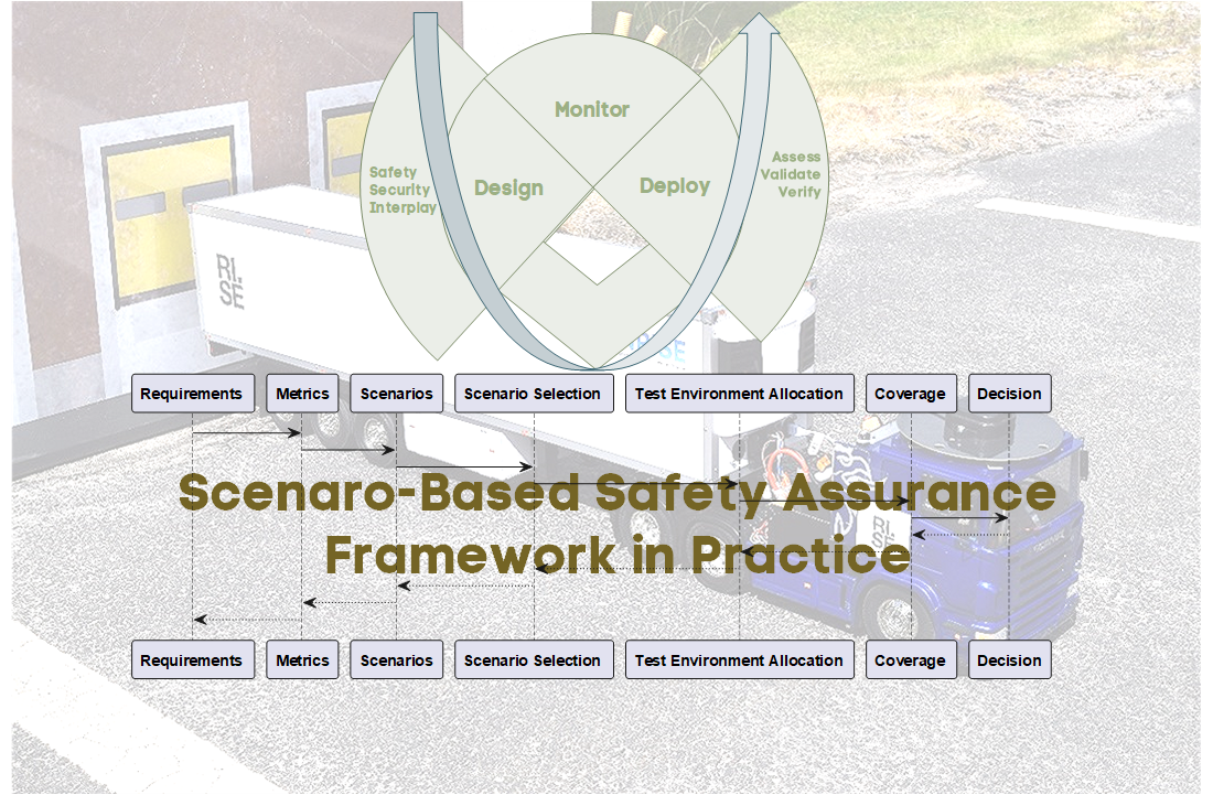
The safety assurance of Connected, Cooperative, and Automated Mobility (CCAM) systems [1] remains a fundamental challenge for large-scale deployment and acceptance. Such systems must reliably operate across various driving scenarios, necessitating a comprehensive safety argumentation framework. As higher levels of automation are pursued, validation through conventional real-world testing becomes impractical due to the vast number of scenarios requiring evaluation. Consequently, a combination of physical and virtual testing has emerged as a more viable solution, with virtual platforms reducing the overall verification and validation effort and addressing the so-called “billion-mile” challenge [2]. Several international initiatives have begun refining test and validation strategies by transitioning from traditional methodologies to scenario-based testing frameworks [3,4]. In scenario-based testing, CCAM systems are evaluated by subjecting the vehicle under test to specific traffic scenarios and environmental parameters to ensure that it behaves safely under various conditions. On the regulatory side, the New Assessment/Test Methodology (NATM) [3] developed by UNECE advances a so-called multi-pillar approach, combining scenario-based testing in simulation and controlled test facilities, real-world testing, audit activities, and in-service monitoring. Figure 1 illustrates the scope of NATM.
However, a considerable gap persists between overarching schematic descriptions in the current frameworks and concrete guidance in the form of well-defined standards or guidelines. While NATM establishes the premises for safety assurance, it offers limited practical guidance on structuring arguments, defining acceptance criteria, and allocating verification activities across environments. The absence of a common validation framework impedes these technologies’ safe and large-scale deployment, with existing or developing standards representing only initial steps toward harmonized assessment. A principal difficulty lies in the lack of comprehensive safety assessment criteria that can be consistently applied across the entire parameter space of driving scenarios, further complicated by regional variations in regulations, signage, and driver behaviour. Several European research projects are paving the way for such a framework, including [5,6,7]. The SUNRISE project [6] developed a Safety Assurance Framework (SAF) focused on input definition and the assessment of top-level vehicle behaviour, i.e., part of the NATM scope (see Figure 1). The framework applies a harmonized scenario representation and draws on a federated European scenario database. It is demonstrated across simulation, XiL-based testing, and proving ground experiments. The approach emphasizes coverage of test scenarios within the Operational Design Domain (ODD) and integrates Key Performance Indicators (KPIs) to support systematic evaluation of safety criteria. Within the assurance process, the KPIs are devised to be explicitly linked to argumentation, thereby substantiating the claims made in the assurance case.
This framework does not require continuous test code maintenance [8] and instead automatically remains current with the traffic environment through a continuously updated database. Relevant scenarios, based on real-world data, may be retrieved by querying the database with ODD and dynamic driving task (DDT) constraints. These data form the basis for generating a well-defined scenario test space, ensuring consistent coverage without imposing excessive testing overhead. Scenario exploration need not be exhaustive but should follow a strategic selection approach, supported by an argument that no significant gaps remain that could give rise to unreasonable risk. Evidence obtained from diverse virtual and physical test environments can be used to demonstrate that the defined KPIs retain validity across varied operational conditions, thereby substantiating the claim of safety and reliability within the designated setting.
This paper contributes by presenting an example of how the recently released SUNRISE SAF [9] can be operationalized, i.e., how the concepts may be translated into concrete practical steps that can be applied for a real-world use-case. This is done by applying a tailored version of the SAF to an ADS feature for trucks providing automated docking at a logistics hub (a truck with a semi-trailer can be parked in a staging area by a human driver, and will then automatically perform a reverse maneuver to dock at the designated port). The use case is evaluated on heterogeneous test environments, including simulation (using CARLA [10,11]), an automated scaled model truck, and a real truck.
A second contribution is showing an integrated, traceable pathway for safety assurance, rather than treating the process as a collection of discrete steps. The pathway formalizes the end-users needs into measurable key performance indicators and acceptance thresholds; defines a parametrized scenario space that couples operational conditions (scenarios within the declared ODD [12]) with internal system conditions; orchestrates exploration in heterogeneous test environments using complementary test models while tracking coverage; interprets outcomes through predefined test metrics and aggregation rules; manages completion via explicit coverage targets and stopping criteria; and consolidates the resulting evidence into a pass/fail judgment that is embedded in a structured safety argument with stated assumptions and limitations. The value lies in the linkages and bidirectional traceability across the elements depicted in Figure 2, where the requirements articulate the needs, and the decision determines whether those needs are met. This yields a coherent workflow that supports consistent allocation, comparable evidence across environments, and defensible claims about exercised scenarios and operational subspaces.
A third contribution is the development of WayWiseR [13], a ROS2-based [14] rapid prototyping platform, and its integration with the CARLA simulation environment [11]. By integrating modular ROS 2 components, simulation environments such as CARLA, and scaled vehicle hardware, the platform enables rapid development, testing, and iteration of validation concepts. The resulting artefacts are released for research use, enabling reproducible experiments and facilitating scenario execution across both simulation and hardware-in-the-loop configurations in a unified manner. While the system architecture of WayWiseR and preliminary results were introduced in earlier work [15], this paper extends that work by presenting comprehensive results and demonstrating its application in SAF validation concepts across both simulation and physical platforms.
The paper is organized as follows. Section 1 introduces the problem; Section 2 reviews background and related work; Section 3 presents the the tailored SAF instance; Section 4 introduces the use case. Section 5 describes the demonstrated cross sections between the SAF and the use case; Section 6 outlines the employed test environments. Section 7 operationalizes and evaluates the SAF, and Section 8 discusses results and outlines directions for future work.
2. Background
Research on safety assurance for CCAM benefits from explicit alignment with the NATM [3], which offers a regulator-oriented frame of reference that can enhance the relevance, comparability, and assessability of evidence across programs and jurisdictions. Developed by the UNECE WP.29/GRVA through its VMAD group, NATM provides a harmonized multi-pillar basis for assessment, supporting type-approval and in-service oversight. This approach addresses the limitations of isolated road testing by integrating audits, scenario-based evaluations, proving-ground trials, and monitored operations. For the United States, NHTSA’s scenario testing framework [4] provides method-level guidance to structure ODD attributes and derive scenario-based tests across simulation, proving-ground, and limited on-road trials.
The SUNRISE [6] SAF aims at serving both development, assessment, and regulation. The SAF integrates a method for structuring safety argumentation and managing scenarios and metrics, a toolchain for virtual, hybrid, and physical testing, and a data framework that federates external scenario sources, supports query-based extraction and allocation, and consolidates results. The project evaluates the SAF through urban, highway, and freight use cases spanning simulation and real-world assets to expose gaps, validate interfaces, and assess evidence generation. The work presented in this paper instantiates the SUNRISE SAF [9] and details how each step of the tailored SAF process in Section 3 can be made actionable for a use case in practice (Section 4). Specifically, the instance clarifies how assumptions and inputs are made explicit, how claims are decomposed into verifiable objectives, how evidence is planned and synthesized with traceability, and how decision points for progression are justified. Together, this provides a concrete pathway from NATM’s high-level expectations to assessable, reproducible activities for the considered use case.
Scenario-based testing for automated driving has gained prominence, underpinned by the ISO 3450x series on test scenarios for automated driving systems [12,16,17,18,19] which can be coupled with proven foundational and verification concepts e.g., as introduced in ISO 29119 Software and systems engineering — Software testing [20].
Operationalizing NATM through scenario databases and multi-pillar testing has been outlined by den Camp and de Gelder [21] in general terms, with particular emphasis on database interaction. The work presented here complements that contribution by addressing some challenges that remain, providing an end-to-end walk-through based on a concrete use case, demonstrating the tracing of external requirements to KPIs, the derivation of scenarios from ODD and DDT, the allocation of test cases, and in particular, assessing whether a given test suite achieves sufficient coverage of the relevant test space is still difficult. A prudent way forward is to develop systematic methods that trace scenario requirements to operational design domain abstractions [22,23] and map them to the capabilities and limitations of heterogeneous test environments [24,25], thereby enabling principled test allocation [26], comparable evidence across environments [27], and defensible coverage claims [28]. This paper advances that direction by tailoring the SUNRISE SAF to operationalize such systematic methods, demonstrating how coverage-oriented allocation can be evaluated in practice.
3. The Tailored SAF
In this paper a tailored instance of the SUNRISE SAF, shown in Figure 3, is used. Each block is described below. For more information about the full SUNRISE SAF, references to SUNRISE deliverables with more detail are also mentioned in the descriptions.
- Test Basis defines the foundation of testing and comprises the ODD space, required behaviour, required test coverage, and test completion criteria. In the information flow, the Test Basis constrains scenario selection in the Scenario DB, specifies test requirements directed to the Environment, and defines the evaluation metrics used in Evaluate. It must be defined in terms of a machine-readable ODD, required behaviour, coverage targets, and completion criteria, as described in ISO 3450X [12,16,17,18,19], ISO 29119 [20], and the SUNRISE requirements on scenario concepts, parameter spaces, and interfaces [29]. A detailed account of the key performance indicators used in this work is provided in Section 5.2.
- Scenario DB supports the creation, formatting, storage, and sharing of scenarios with traceability and standardised formats. It receives constraints from the Test Basis, provides logical scenarios to the Environment, and enables query-based retrieval to support test design and execution. The SUNRISE data framework requirements [30] define the content, metadata, provenance, and result storage needs for external scenario databases, while the SCDB methodology specifies how external repositories are integrated and accessed consistently. In this study, Section 5.3 introduces a surrogate implementation that emulates interaction with a real database.
- Environment transforms logical scenarios into executable test cases. It begins with Select & Concretise, where scenarios are instantiated and bound to test objectives. These are then Allocated to appropriate test environments, followed by Execution. Results from execution are forwarded to the Evaluate block. This builds on the harmonised V&V simulation framework developed in SUNRISE [31], which connects scenario definitions to execution platforms and testbeds. The implementation of the tailored environments used in this work is described in Section 6.
- Evaluate applies the metrics defined in the Test Basis to the test results. It comprises Test Evaluate and Coverage, both of which feed into the construction of the Safety Case (See Section 5.2). The safety case then informs the Decide step when the test completion criteria are met, and then judgments can be made. Outcomes from evaluation provide feedback to earlier blocks, enabling iterative refinement. Evaluation is detailed in SUNRISE SAF demonstration instances [32], which illustrate how test evidence is integrated into safety-case arguments. Refinements of test attributes into a minimal essential set for allocation and evaluation are provided in [33]. The evaluation results for the case study are presented in Section 7.
Building on the ISO 3450X standards for test scenarios [12,16,17,18,19], Figure 3 schematically illustrates four main stages of a scenario-based safety assurance process, situating the test case allocation method in context and aligning with approaches such as [3,4,9]. Continuous feedback between these blocks is essential to enhance the robustness and reliability of the assessed systems. This tailored instance, therefore, operationalizes selected elements of the broader SUNRISE SAF to demonstrate and evaluate their application in a concrete case study.
4. Use Case Description: Automated Parking of a Truck with Semi-Trailer
The use case chosen to demonstrate the operationalized tailored SAF is automated reverse parking of a truck with a semi-trailer at a logistics hub illustrated in Figure 4. It is a sub-use case from the domain of confined area use cases, identified in the ERTRAC CCAM Roadmap [34] as one of five domains for innovation related to the introduction of CCAM systems, like “Automated trucks for operation in logistics terminals, quarries and construction sites” and “Trucks in hub-to-hub operation between terminals”. Confined areas are attractive for early introduction of CCAM systems as they typically have a limited ODD. Usually, they show low risk for unauthorized vehicle and people presence as they commonly have some type of perimeter protection, entry gate control, and are under some type of supervision. There may be mixed traffic combining manually operated vehicles with Automated Guided Vehicles and other automated vehicles. Further, they commonly operate at low speed; there could be specific traffic regulations.
Reverse parking manoeuvres for truck-trailer combinations are challenging and have been studied in, e.g., [35,36,37,38,39,40], and [40] summarizes why automated parking functions are needed:
- For a human driver, commonly several manoeuvres are needed to bring the trailer into the correct parking position.
- A main concern is the time spent positioning the trailer.
- Especially for construction sites, it is also concerned with surrounding traffic and other road users, such as pedestrians.
5. Demonstrating the Tailored SAF
The tailored SAF is applied to the automated parking use case introduced in Section 4, focusing on performance within defined operational conditions and compliance with safety requirements. The demonstration follows the SAF workflow, from requirements definition and ODD specification to scenario development, allocation, execution, and evaluation.
5.1. Requirements
System requirements are derived from end-user needs and provide the foundation for subsequent scenario development and evaluation. The automated truck begins its manoeuvre from a designated staging area and must be able to traverse a busy logistics hub in a manner comparable to human-driven vehicles. Its behaviour shall be predictable and bounded, ensuring that other road users can anticipate its actions. The truck shall only engage the automated parking function when all required operating conditions are fulfilled. During the manoeuvre, the truck shall avoid collisions with static and dynamic objects. If the truck is unable to handle the situation, it shall always be capable of transitioning to a safe state by coming to a controlled stop. Finally, the truck shall be able to reverse into a docking position and park the trailer with high accuracy. A schematic view of the user needs is shown in Figure 5 with numbers concluded based on discussions with truck drivers from Chalmers Revere.
5.2. Metrics
The safety goals (SG) were identified through hazard analysis and risk assessment (HARA) [41,42]. From these, two goals were selected as particularly relevant, showcasing the substantiation of the claims that must be made to fulfill the system requirements. These goals serve as the basis for defining key performance indicators (KPIs) that support the systematic evaluation of safety criteria. The selected safety goals are:
- SG1: The vehicle shall not collide.
- SG2: The vehicle shall not operate if the required conditions are not fulfilled.
Based on these safety goals, three KPIs were defined to operationalize the evaluation. Each KPI targets a specific aspect of safe operation, ranging from docking precision to bounded manoeuvring and robustness under varying operational conditions. The KPIs are not intended solely for a one-time assessment prior to market release but are equally relevant for monitoring during the service life of the system. Their careful selection is therefore critical to ensure that they remain valid and measurable over time, supporting both the initial safety argument and ongoing lifecycle assurance. In this way, the KPIs contribute not only to demonstrating compliance at the point of release but also to substantiating maintained compliance throughout operation.
- KPI1
- evaluates the docking precision of the semitruck by repeatedly starting from the same position. Figure 6 shows a schematic illustration of the test setup, where the light condition specified by the ODD is daylight.
- KPI2
- introduces a safety zone where the truck is expected to move. The starting position varies in this scenario, and the test examines whether the truck remains inside the safety zone. The indicator is schematically illustrated in Figure 6, with sensor conditions optimized for daylight. TO increase complexity, the ODD can be extended to include reduced-light scenarios, enabling assessment of how the semitruck performs in dimmed conditions.
- KPI3
- focuses on variations in the ODD by adding the presence of obstructing objects and altering environmental factors. As shown in Figure 6, this setup allows deeper exploration of the truck’s performance under changing conditions to ensure robust compliance with safety requirements.
These KPIs are shown in Figure 6 together with the safety zone introduced in KPI2.
5.3. Scenario Selection and Allocation
The complete scenario space for the automated parking function consists of all admissible combinations of operational design domain parameters, infrastructure constraints, internal system states, and dynamic interactions. In a full-scale implementation, subsets of this space would be retrieved through structured queries to a scenario database to ensure traceability and reproducibility.
Exploring the full space in physical testing is infeasible; therefore, representative subsets are derived using coverage and hazard relevance criteria in the Select & Concretise block. The result is a smaller test space to be handled in the Allocation block of the SAF, where scenarios are assigned to the most suitable test environments. This allows defensible evidence to be obtained with minimal effort by relying primarily on simulation, complemented with selected physical tests for validation. Nominal docking runs are typically executed in simulation, while edge cases, such as extreme starting angles or reduced visibility, are verified physically. If coverage gaps or uncertainties are identified, scenarios can be reallocated iteratively to alternative environments.
During this work, no scenario database was available. Instead, a logical scenario was defined from experiments with Chalmers Revere’s full-scale Volvo FH16 “Rhino” truck, supported by input from an experienced driver. Recorded GNSS trajectories of repeated parking manoeuvres are shown in Figure 7. The logical scenario is illustrated in Figure 8, covering possible positions and orientations of the truck and trailer within a square staging area, with environmental parameters set to baseline conditions.
The initial scenario allocation process defined in [33] compares test case requirements with test environment capabilities to select the most suitable environment. Skoglund et al. [23,25] proposed an automated method for this comparison, using a formalized ODD with key testing attributes. In the tailored SAF, this ensures systematic distribution of test cases and defensible evidence generation across simulation and physical testing, directly linking the Allocation step to the subsequent Coverage and Decide blocks.
Concrete scenarios for physical testing were selected by varying the starting positions of the truck and trailer within the staging area (Figure 8). A combinatorial testing approach [33] was applied, including a nominal case where the truck and trailer were aligned at the center, and 16 edge cases defined by corner starting positions. These cases are shown in Figure 9.
6. Test Environment Setup
To validate the SAF, we used WayWiseR [13,15], an open-source rapid prototyping platform internally developed by RISE for connected and automated vehicle (CAV) validation research. Built on ROS2, WayWiseR incorporates the WayWise library [43] to provide direct access to motor controllers, servos, IMUs, and other low-level vehicle hardware. With its modular ROS2 architecture, WayWiseR supports unified testing across simulation and physical platforms, enabling the same implementation to run in CARLA and on the 1:14-scale truck. Figure 10 illustrates the WayWiseR test execution framework, showing its building blocks and control flow for unified physical and virtual testing. An automated reverse parking functionality for a semitruck was implemented in the WayWise library and was wrapped into the WayWiseR autopilot ROS2 node. It should be noted that the implemented reversing function only has functionality necessary for the described demonstration; the implementation is not product-ready.
As previously described, there is work presented in the literature related to automated or assistant reversing of truck–trailer systems [35,36,37,38,39,40]. In common is that they are all for low speed and assume that a simplified linear bicycle model is sufficient for kinematic modelling. Wheels on the same axis are approximated to one wheel in the middle of the axis, multiple axes at one end of the vehicle are approximated into a single axis, and no wheel slip is assumed. The vehicle position control is usually achieved through feedback of the hitch angle (the difference in heading between truck and trailer) based on a linearized system approximation. Path tracking is mostly done using variants of the pure pursuit algorithm [44]. For the reversing function used in the paper, a similar algorithm using the Lyapunov controller [45,46] was found suitable.
For a first evaluation, the mathematical model of the reversing algorithm, together with a simplified kinematic model of the semi-truck, was implemented using Python. An example of using it is seen in Figure 11 showing Monte-Carlo simulations of the trajectories.
6.1. Simulation Environment
The simulation environment was implemented using CARLA v0.9.15 [10], which was extended and customized to meet the requirements of the reversing use case. The base scenario was developed on the existing Town05 map, where one of its parking areas was modified to resemble a realistic logistics hub. As CARLA does not natively provide articulated trucks, new vehicle assets were introduced: a six-wheeled Scania R620 tractor and a compatible semitrailer, both adapted from publicly available 3D CAD models. These models were adapted using Blender and subsequently imported into CARLA, allowing for visually and physically accurate representations of the vehicle combination.
To enable realistic articulation behaviour, a custom coupling mechanism was implemented within CARLA using its blueprint functionality. This mechanism introduces a physics constraint between the truck and the trailer, activated when both are positioned in proximity, so that they behave as a connected articulated vehicle during simulation. The simulation environment was fully integrated with the WayWiseR platform through a modified carla-ros-bridge, ported to ROS 2 Humble and deployed on Ubuntu 22.04. Figure 12 illustrates the customized CARLA environment with the imported truck–trailer model, performing a reversing manoeuvrer.
6.2. Scaled Testing Environment
The scaled testing environment uses a 1:14-scale Tamiya Scania R620 model truck coupled with a matching Tamiya semi-trailer of the same scale. To closely mirror the simulated logistics hub, its 3D CAD model from CARLA was used to generate a 1:14-scale printout of the hub’s front facade, representing the docking environment in the scaled setup. A flat parking lot was used to recreate the hub area, with the staging area marked on the ground and the docking hub positioned according to the 1:14 scale and following scenario specifications. This setup, shown in Figure 13 and Figure 14, provided a controlled environment for the repeated tests involving docking manoeuvres with the model semi-truck.
Several modifications were made to the truck and semi-trailer models to enable the tests, including the installation of a GNSS antenna on the roof of the cabin, a magnetic angle sensor to measure the hitch angle, and a high-precision GNSS positioning module (u-blox ZED-F9R [47]) that is capable of delivering centimeter-level accuracy. A brushed DC motor for driving and a servo motor for steering were installed, both controlled via an open-source Vedder electronic speed controller (VESC) [48] motor controller, which WayWiseR can interface with directly to regulate driving speed and steering. The truck model is equipped with a Raspberry Pi 5 running Ubuntu 24.04. Sensor readings, control loop execution, motor actuation, data logging, and test orchestration are all coordinated seamlessly by WayWiseR on this onboard computer.
During each test execution, the truck was positioned in the staging area via manual control using a teleoperated joystick interfaced through WayWiseR, ensuring precise placement according to scenario specifications. Once positioned, the vehicle autonomously executed the reversing manoeuvre to the docking area following WayWiseR autopilot commands, while all sensor data, control signals, and state information were logged by WayWiseR Test Runner for subsequent validation. The ROS2 interface through WayWiseR also allowed remote monitoring of the test in real time through RViz as shown in Figure 15, with the ability to issue an emergency stop through the joystick if needed.
7. Results
KPI1 demonstrates consistent docking precision with variability primarily due to sensor uncertainty. KPI2 reveals stable manoeuvres with occasional safety-zone infractions caused by positioning inaccuracy. KPI 3 confirms that the tailored framework ensures sufficient coverage and fidelity of test environments for object-detection validation without direct testing.
Common for all performed tests is that the trucks start from the staging area. For the physical tests with the scaled model truck, the starting positions are limited to the positions shown in Figure 9. Same positions are used for the simulation, but complemented with positions distributed over the staging area. A photo of the model truck parked in the staging area corresponding to one of the starting positions shown in Figure 9 is shown in Figure 16.
An important limitation is that the model truck depends on the GNSS position for navigation along the intended trajectory. To keep GNSS accuracy during the test, it is necessary to drive the truck into the desired position in the staging area and afterwards lift the trailer to the correct position. Manually lifting the truck and adjusting its position will result in lost GNSS position accuracy. Consequently, this limitation in how precisely the truck can be parked impacts the repeatability and accuracy of the physical tests with the model truck.
7.1. Evaluation of Docking Precision for KPI1
KPI1 is defined in Section 5.2 as the docking precision of the semitruck when repeatedly starting from the same position. To evaluate this KPI, tests were conducted under clear, sunny daylight conditions in both simulation and with the scaled model truck. Figure 17 presents the results from 50 repeated tests in simulation and 10 runs with the scaled truck with the nominal starting position in the staging area. It can be noted that the distribution of trajectories across runs is tightly clustered in both simulation and physical tests, indicating high precision in following the intended path when starting from the nominal position in the staging area.
The distribution of semitrailer’s docking errors for both simulation and real truck tests is illustrated in Figure 18 and its statistics are summarized in Table 1. In both environments, a small lateral shift to the left is observed. When accounting for scale, the lateral errors () are similar in both environments. However, the simulation exhibits larger positive longitudinal errors (), which may be attributed to the higher momentum of the full-scale vehicle and the correspondingly longer braking distance. This suggests that minor adjustments between the physical scaled prototype and the simulation models may be needed to reproduce longitudinal stopping characteristics better. Overall, the narrow ranges of both lateral and longitudinal errors indicate that the docking maneuvers are executed with high precision and consistency across repeated runs in both environments.
7.2. Safety Zone Infractions Evaluated for KPI2
The safety zone, as indicated in Figure 13, is important for the safety evaluation of the AD function. It defines the geometrical area inside which the truck with a semitrailer is expected to stay during the reverse parking manoeuvre. The exact dimensions of the safety zone will be a trade-off between the AD vehicle performance and the geometrical dimensions of the site where the vehicle will operate. The result here has a focus on the methodology rather than an exact numerical threshold.
For KPI2, the starting position may be anywhere inside the staging area. The tests aim to determine whether the truck remains within the defined safety zone. In this evaluation, environmental conditions in the ODD are assumed to be nominal, i.e., no functional limitations from external factors such as GNSS signal quality are present. For a full systematic assessment, the ODD could be extended to include more challenging conditions, e.g., reduced GNSS signal reliability or other disturbances.
To evaluate this KPI, tests were conducted under clear, sunny daylight conditions using the implemented AD function in the WayWiseR platform in both simulation and with the scaled model truck. Figure 19 presents the results for different test runs from simulations and physical tests with various start positions distributed across the staging area. To achieve broader coverage in simulation, the scenario-defining parameters (i.e., truck’s start position, truck heading, truck-trailer hitch angle) were discretized, and 200 scenarios were randomly generated. This set includes the 16 edge-case starting positions shown in Figure 9, ensuring both typical and extreme conditions are represented in the analysis. For the physical tests using the scaled truck, 17 scenarios were selected, which include the nominal start position and the 16 edge-case starting positions from Figure 9.
The results, shown in Figure 19a,b, display similar overall behavior across both environments. While most runs follow the target trajectory closely, some exhibit larger deviations, particularly for edge-case starting positions. In physical tests, additional variability arises from manual positioning of the scaled truck and from measurement uncertainties in the RTK-GNSS positioning system, which can be significant at the small scale of the model.
Figure 20 shows the deviations of the semitrailer’s rear-axle middle positions from the planned trajectory along the path from start to end for both simulation and scaled truck tests. In both environments, two prominent peaks are observed: one directly after the start due to variations in the initial heading and trailer angle, and another at the turn along the path. Although the overall shapes of the distributions are similar, the observed discrepancies, particularly in the second peak magnitude, highlight the need for further adjustments to better align the simulation model with the physical prototype.
7.3. Suitability of Test Environment and Validation Coverage for KPI3
The evaluation does not directly specify or implement and test KPI 3 ODD conditions for object detection. Instead, it focuses on the adequacy of test environments required for such validation. Within the tailored SAF workflow (Figure 3), test requirements derived from the ODD are constrained, from which scenarios are concretised, allocated, and executed across different environments. The resulting evidence is then evaluated with respect to coverage and its contribution to the assurance case.
In this context, ODD-dependent aspects of KPI 3 are within the scope of the SAF. The automated allocation process suggested in the tailored framework not only ensures that test environments can represent ODD parameters but also that they are characterised through additional capabilities essential for validation. These include Safety Hazard Mitigation Capability, which concerns the ability to minimise risks to participants, such as safety drivers or observers; Test Complexity Capability, which reflects the degree of orchestration and diversity of test elements and ODD conditions that can be accommodated; Test Environment Fidelity Capability, which measures how accurately the environment reproduces real-world conditions relevant to the coverage item; and System Under Test (SUT) Fidelity Capability, which assesses the extent to which a model corresponds to its intended production implementation, particularly in virtual environments or test harnesses [25].
By systematically integrating these environmental attributes with formalised ODD parameters, the SAF provides a means of determining whether a given environment is suitable for supporting KPI 3 validation. Although direct object-detection testing is not performed, the framework ensures that the environmental conditions necessary for such assessments are adequately represented, traceable, and capable of generating credible evidence for the assurance case.
8. Conclusions
A commonly accepted safety assurance framework is vital for enabling harmonized assessment, which is needed for large-scale deployment and acceptance of CCAM systems. Initiatives such as SUNRISE have defined assurance frameworks; however, practical guidelines on how to apply a framework to CCAM functions are still needed, including key challenges such as defining metrics and acceptance criteria, selecting scenarios, and allocating tests to heterogeneous test environments; all to collectively provide a defensible argument for the safety of the system.
This paper has shown a path towards operationalizing the safety assurance framework developed within the SUNRISE project. This is done by applying a tailored version (representing a subset of the SUNRISE SAF) to a practical CCAM use case, which is evaluated with heterogeneous test environments. For this use case, we have shown how KPI definition, scenario selection, test environment allocation, and evaluation can be performed.
The demonstration has some limitations. Our use case has quite a restricted ODD, which makes some of the steps much simpler than, for e.g., an ADS feature intended for use on public roads. Hence, we have not touched upon the issue of scenario collection and building useful scenario databases for such complex use cases, where completeness and edge cases are harder questions. Defining good KPIs will also be a more complex task for such use cases. We have also focused on safety-related KPIs, but note that a full assurance case needs to consider additional aspects such as cybersecurity (in particular security-informed safety [49]) and safe human interaction (including reasonable foreseeable misuse). Another issue that falls outside the SUNRISE SAF is the in-service monitoring and reporting integrated in NATM. As CCAM features operate in a changing environment, monitoring for the continuous validity of the assurance case is of vital importance to manage issues such as component ageing and concept drift, which can affect machine learning and predictive analytics components in the system. For this reason, we believe KPIs should be formulated for continuous monitoring and not only as a one-time pre-deployment verdict. Within each of these areas, open questions for future research remain.
Author Contributions
Conceptualization, M.S.; Methodology, M.S.; Validation, R.R.A.; Investigation, M.S., A.T., and R.R.A.; Writing – original draft, M.S., A.T., and R.R.A.; Writing – review and editing, M.S., A.T., R.R.A., K.L., and F.W. All authors have read and agreed to the published version of the manuscript. Authorship is limited to those who have contributed substantially to the work.
Funding
The SUNRISE project is funded by the European Union’s Horizon Europe Research and Innovation Actions under grant agreement no.101069573. The views and opinions expressed are, however, those of the author(s) only and do not necessarily reflect those of the European Union or the European Union’s Horizon Europe Research and Innovation Actions.
Acknowledgments
The authors thank Fredrik Von Corswant and Daniel Poveda Pi at Chalmers’ REVERE lab for discussions, photos, and trajectory data from tests with Chalmers’ Volvo FH16 truck.
Conflicts of Interest
The authors declare that the research was conducted in the absence of any commercial or financial relationships that could be construed as a potential conflict of interest.
References
- CCAM. European Partnership on Connected, Cooperative and Automated Mobility. Available online: https://www.ccam.eu/ (accessed on 2023-05-31).
- Kalra, N.; Paddock, S.M. Driving to Safety: How Many Miles of Driving Would It Take to Demonstrate Autonomous Vehicle Reliability? Transportation Research Part A: Policy and Practice 2016, 94, 182–193. [Google Scholar] [CrossRef]
- ECE/TRANS/WP.29/2021/61. (GRVA) New Assessment/Test Method for Automated Driving (NATM) - Master Document | UNECE, 2021.
- Thorn, E.; Kimmel, S.C.; Chaka, M.; Virginia Tech Transportation Institute.; Southwest Research Institute.; Booz Allen Hamilton, Inc. A Framework for Automated Driving System Testable Cases and Scenarios. Technical Report DOT HS 812 623, NHTSA, 2018.
- HEADSTART. Evaluation Results of Application and Demonstration. Available online: https://www.headstart-project.eu/results-to-date/deliverables/ (accessed on 2024-09-20).
- Sunrise Project | Developing and Providing a Harmonized and Scalable CCAM Safety Assurance Framework. Available online: https://ccam-sunrise-project.eu/ (accessed on 2024-10-17).
- CCAM. Synergies. Available online: https://synergies-ccam.eu/ (accessed on 2025-05-28).
- Kaner, C. An Introduction to Scenario Testing. Software Testing & Quality Engineering (STQE) magazine, 2003, 1. [Google Scholar]
- SUNRISE Safety Assurance Framework - High-Level Overview. Available online: https://ccam-sunrise-project.eu/high-level-overview/ (accessed on 2025-02-25).
- Dosovitskiy, A.; Ros, G.; Codevilla, F.; Lopez, A.; Koltun, V. CARLA: An Open Urban Driving Simulator, 2017, [arXiv:cs/1711.03938]. [CrossRef]
- GitHub - WayWiseR/Waywiser_carla at Humble · RISE-Dependable-Transport-Systems/WayWiseR. Available online: https://github.com/RISE-Dependable-Transport-Systems/WayWiseR/tree/humble/waywiser_carla (accessed on 2025-08-28).
- International Organization for Standardization. ISO 34503:2023 - Road Vehicles — Test Scenarios for Automated Driving Systems — Specification for Operational Design Domain.
- GitHub - RISE-Dependable-Transport-Systems/WayWiseR. Available online: https://github.com/RISE-Dependable-Transport-Systems/WayWiseR (accessed on 2025-08-28).
- Macenski, S.; Foote, T.; Gerkey, B.; Lalancette, C.; Woodall, W. Robot Operating System 2: Design, Architecture, and Uses in the Wild. Science Robotics 2022, 7, eabm6074. [Google Scholar] [CrossRef] [PubMed]
- Avula, R.R.; Damschen, M.; Mirzai, A.; Lundgren, K.; Farooqui, A.; Thorsen, A. WayWiseR: A Rapid Prototyping Platform for Validating Connected and Automated Vehicles. under review, submitted to the 13th International Conference on Control, Mechatronics and Automation (ICCMA 2025).
- International Organization for Standardization. ISO 34501:2022 - Road Vehicles — Road Vehicles — Test Scenarios for Automated Driving Systems — Vocabulary.
- International Organization for Standardization. ISO 34502:2022 - Road Vehicles — Test Scenarios for Automated Driving Systems — Scenario Based Safety Evaluation Framework.
- International Organization for Standardization. ISO 34504:2024 - Road Vehicles — Test Scenarios for Automated Driving Systems — Scenario Categorization.
- International Organization for Standardization. ISO 34505:2025 - Road Vehicles — Test Scenarios for Automated Driving Systems — Scenario Evaluation and Test Case Generation.
- ISO/ICE/IEEE. ISO/ICE/IEEE 29119 - Software and Systems Engineering - Software Testing, 2022.
- Olaf Op den Camp.; Erwin de Gelder. Operationalization of Scenario-Based Safety Assessment of Automated Driving Systems, 2025, [arXiv:cs/2507.22433]. [CrossRef]
- Menzel, T.; Bagschik, G.; Isensee, L.; Schomburg, A.; Maurer, M. From Functional to Logical Scenarios: Detailing a Keyword-Based Scenario Description for Execution in a Simulation Environment, 2019, [arXiv:cs/1905.03989]. [CrossRef]
- Skoglund, M.; Warg, F.; Thorsén, A.; Hansson, H.; Punnekkat, S. Formalizing Operational Design Domains with the Pkl Language. In Proceedings of the 2025 IEEE Intelligent Vehicles Symposium (IV); 2025; pp. 1482–1489. [Google Scholar] [CrossRef]
- Zhao, X.; Aghazadeh-Chakherlou, R.; Cheng, C.H.; Popov, P.; Strigini, L. On the Need for a Statistical Foundation in Scenario-Based Testing of Autonomous Vehicles, 2025, [arXiv:cs/2505.02274]. [CrossRef]
- Skoglund, M.; Warg, F.; Thorsén, A.; Punnekkat, S.; Hansson, H. Methodology for Test Case Allocation Based on a Formalized ODD. In Proceedings of the Computer Safety, Reliability, and Security. SAFECOMP 2025 Workshops; Törngren, M.; Gallina, B.; Schoitsch, E.; Troubitsyna, E.; Bitsch, F., Eds., Cham, 2026; pp. 61–72. [CrossRef]
- Feng, S.; Feng, Y.; Yu, C.; Zhang, Y.; Liu, H.X. Testing Scenario Library Generation for Connected and Automated Vehicles, Part I: Methodology. IEEE Transactions on Intelligent Transportation Systems 2021, arXiv:cs/1905.03419]22, 1573–1582. [Google Scholar] [CrossRef]
- de Gelder, E.; Buermann, M.; den Camp, O.O. Coverage Metrics for a Scenario Database for the Scenario-Based Assessment of Automated Driving Systems. In Proceedings of the 2024 IEEE International Automated Vehicle Validation Conference (IAVVC); 2024; pp. 1–8. [Google Scholar] [CrossRef]
- Weissensteiner, P.; Stettinger, G.; Khastgir, S.; Watzenig, D. Operational Design Domain-Driven Coverage for the Safety Argumentation of Automated Vehicles. IEEE Access 2023, PP, 1–1. [Google Scholar] [CrossRef]
- D3.2 Report on Requirements on Scenario Concepts Parameters and Attributes | Sunrise Project. Available online: https://ccam-sunrise-project.eu/deliverable/d3-2-report-on-requirements-on-scenario-concepts-parameters-and-attributes/ (accessed on 2025-08-25).
- D5.1 Requirements for CCAM Safety Assessment Data Framework Content | Sunrise Project. Available online: https://ccam-sunrise-project.eu/deliverable/d5-1-requirements-for-ccam-safety-assessment-data-framework-content/ (accessed on 2025-08-25).
- D4.4 Report on the Harmonised V&V Simulation Framework | Sunrise Project. Available online: https://ccam-sunrise-project.eu/deliverable/d4-4-report-on-the-harmonised-vv-simulation-framework/ (accessed on 2025-08-25).
- D7.2 Safety Assurance Framework Demonstration Instances Design | Sunrise Project. Available online: https://ccam-sunrise-project.eu/deliverable/d7-2-safety-assurance-framework-demonstration-instances-design/ (accessed on 2025-02-21).
- D3.3 Report on the Initial Allocation of Scenarios to Test Instances | Sunrise Project. Available online: https://ccam-sunrise-project.eu/deliverable/d3-3-report-on-the-initial-allocation-of-scenarios-to-test-instances/ (accessed on 2025-02-21).
- ERTRAC Working Group: “Connectivity and Automated Driving”,. Connected, Cooperative and Automated Mobility Roadmap, 2024.
- Kıvançlı, G. Auto-Trailer Parking Project & HIL Studies. Available online: https://ipg-automotive.com/fileadmin/data/events/apply_and_innovate/tech_weeks/presentations/IPG_Automotive_TECH_WEEKS_Ford_Otosan__Auto_Trailer_.pdf (accessed on 2025-01-10).
- Hamaguchi, Y.; Raksincharoensak, P.; Hino Motors, Ltd. 3-1-1 Hinodai, Hino, Tokyo 191-8660, Japan.; Tokyo University of Agriculture and Technology 2-24-16 Naka-cho, Koganei, Tokyo 184-8588, Japan. Automated Steering Control System for Reverse Parking Maneuver of Semi-Trailer Vehicles Considering Motion Planning by Simulation of Feedback Control System. Journal of Robotics and Mechatronics 2020, 32, 561–570. [CrossRef]
- CORDIS | European Commission. Improved Trustworthiness and Weather-Independence of Conditional Automated Vehicles in Mixed Traffic Scenarios | TrustVehicle Project | Fact Sheet | H2020.
- Trustvehicle. https://www.trustvehicle.eu/. Available online: https://www.trustvehicle.eu/ (accessed on 2024-03-14).
- Ljungqvist, O. Motion Planning and Stabilization for a Reversing Truck and Trailer System. PhD thesis, Linköping University, Department of Electrical Engineering, 2015.
- Manav, A.C.; Lazoglu, I.; Aydemir, E. Adaptive Path-Following Control for Autonomous Semi-Trailer Docking. IEEE Transactions on Vehicular Technology 2022, 71, 69–85. [Google Scholar] [CrossRef]
- International Organization for Standardization. ISO 26262:2018 - Road Vehicles – Functional Safety.
- International Organization for Standardization. ISO/PAS 21448:2019 Road Vehicles — Safety of the Intended Functionality.
- Damschen, M.; Häll, R.; Mirzai, A. WayWise: A Rapid Prototyping Library for Connected, Autonomous Vehicles. Software Impacts 2024, 21, 100682. [Google Scholar] [CrossRef]
- Coulter, R.C. Implementation of the Pure Pursuit Path Tracking Algorithm. Technical Report CMU-RI-TR-92-01, Carnegie Mellon University, Pittsburgh, PA, 1992.
- Elhassan, A. Autonomous Driving System for Reversing an Articulated Vehicle. PhD thesis, KTH, 2015.
- Kvarnfors, K. Motion Planning for Parking a Truck and Trailer System; KTH Royal Institute of Technology, 2019.
- ZED-F9R Module. Available online: https://www.u-blox.com/en/product/zed-f9r-module (accessed on 2025-08-28).
- The VESC Project. Available online: https://vesc-project.com/ (accessed on 2025-08-28).
- Skoglund, M.; Warg, F.; Hansson, H.; Punnekkat, S. Black-Box Testing for Security-Informed Safety of Automated Driving Systems. In Proceedings of the 2021 IEEE 93rd Vehicular Technology Conference (VTC2021-Spring); 2021; pp. 1–7. [Google Scholar] [CrossRef]
Figure 1.
Conceptual illustration of the Multi-pillar safety performance assurance framework, integrating operational requirements and test objectives, audit of safety management artefacts, and in-service monitoring of operational assumptions and system health.
Figure 1.
Conceptual illustration of the Multi-pillar safety performance assurance framework, integrating operational requirements and test objectives, audit of safety management artefacts, and in-service monitoring of operational assumptions and system health.
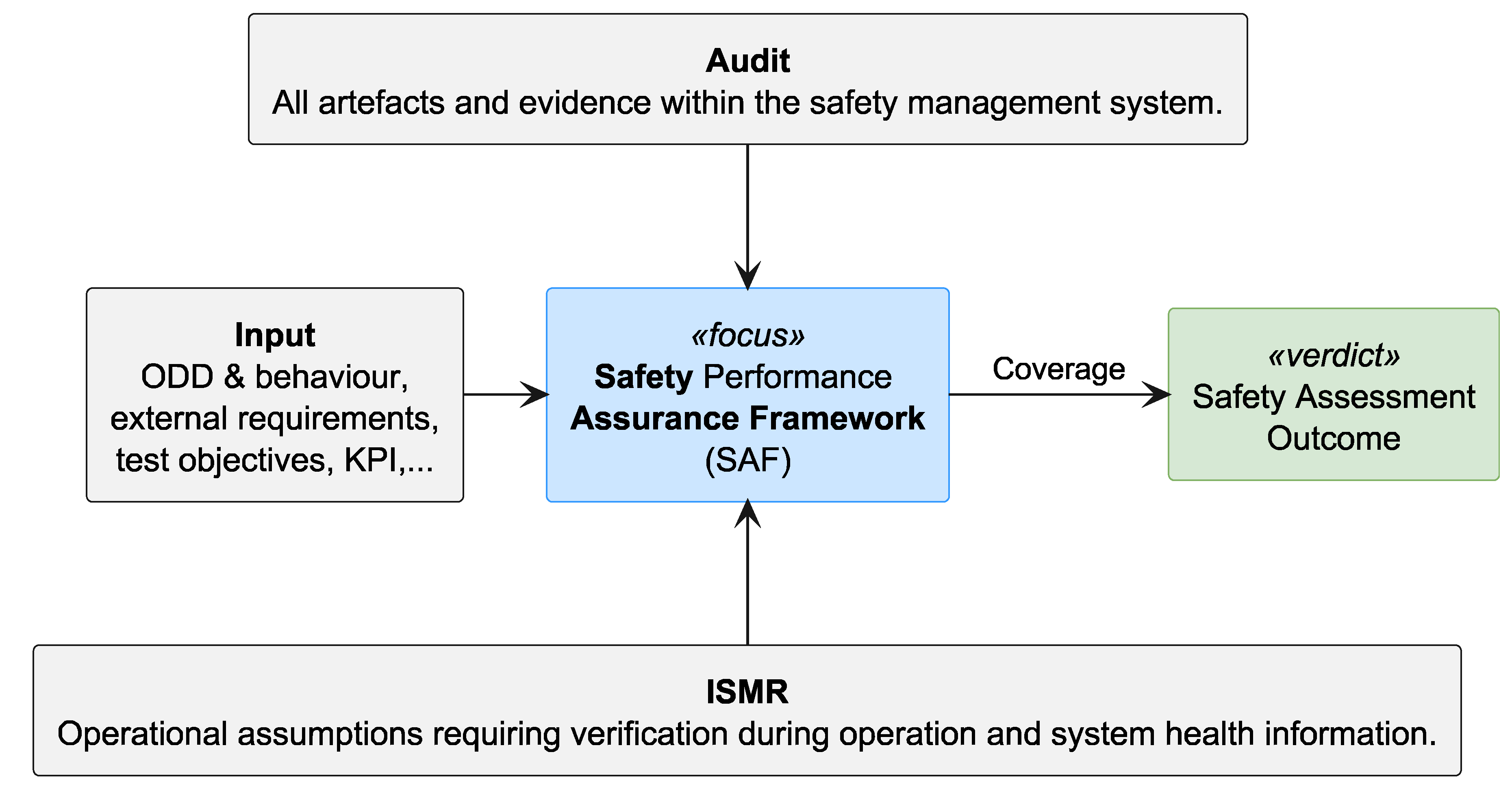
Figure 2.
Bidirectional traceability across the integrated pathway for safety assurance.

Figure 3.
Conceptual overview of the scenario-based test design and implementation workflow in the SAF: the test basis (ODD, required behaviour, required coverage, and completion criteria) constrains the response from the Scenario DB [9]; he retrieved scenarios are concretised and allocated to and to test environments, and the resulting evidence supports evaluation activities encompassing test evaluation, coverage assessment, safety-case substantiation, and finally a judgment.
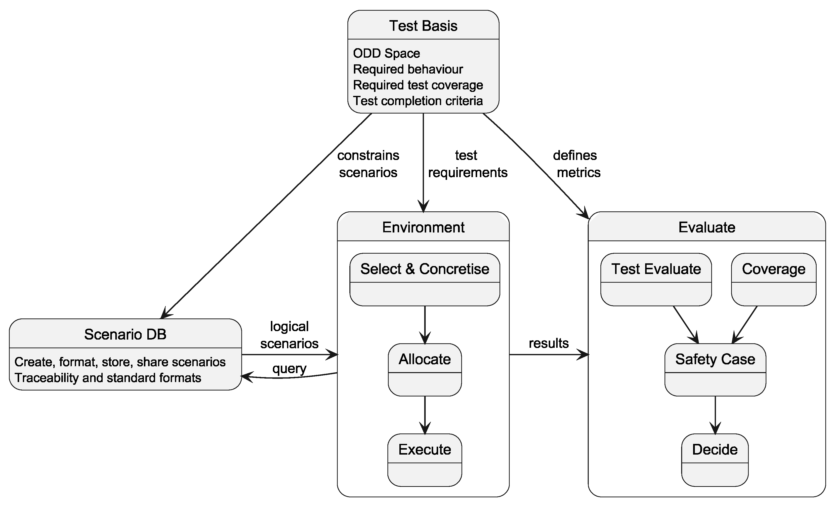
Figure 4.
A truck with a semitrailer preparing to dock at a logistic hub.
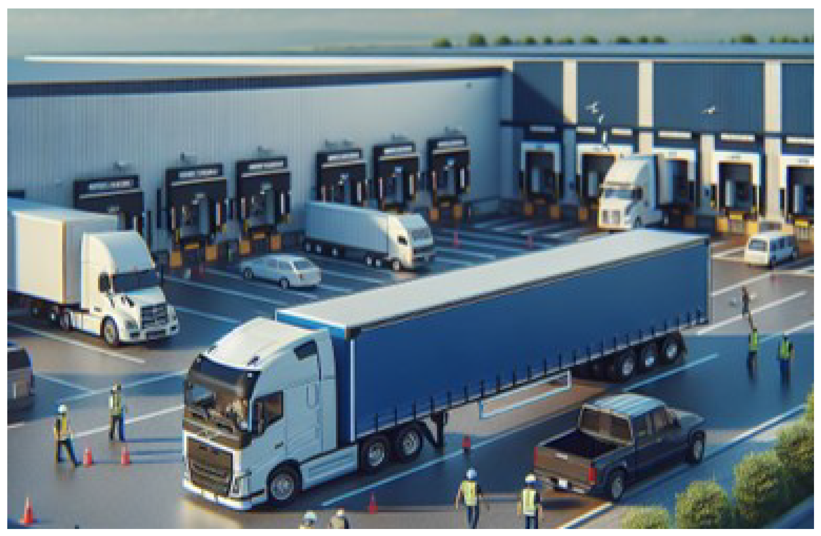
Figure 5.
Description of the end user needs.
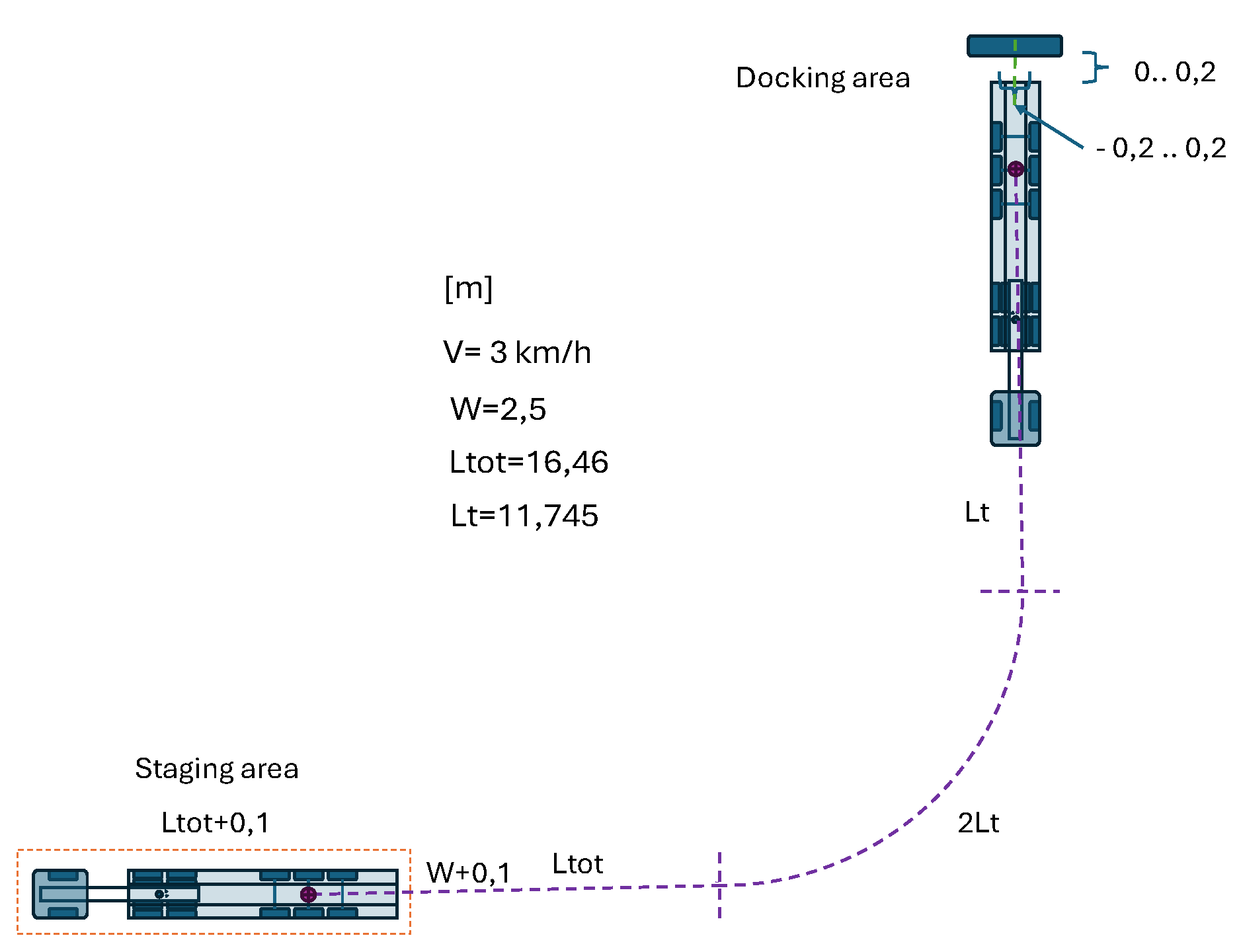
Figure 6.
The investigated three KPIs.
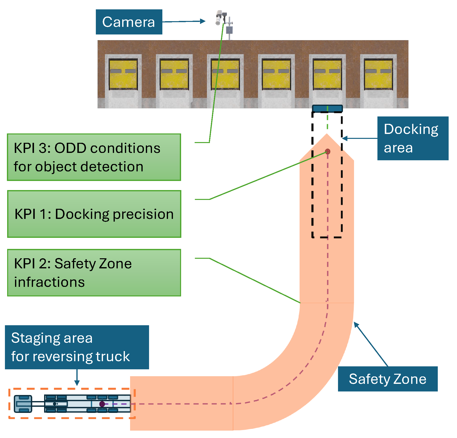
Figure 7.
GNSS trajectories in meter from the truck performing repeated parking manoeuvres.
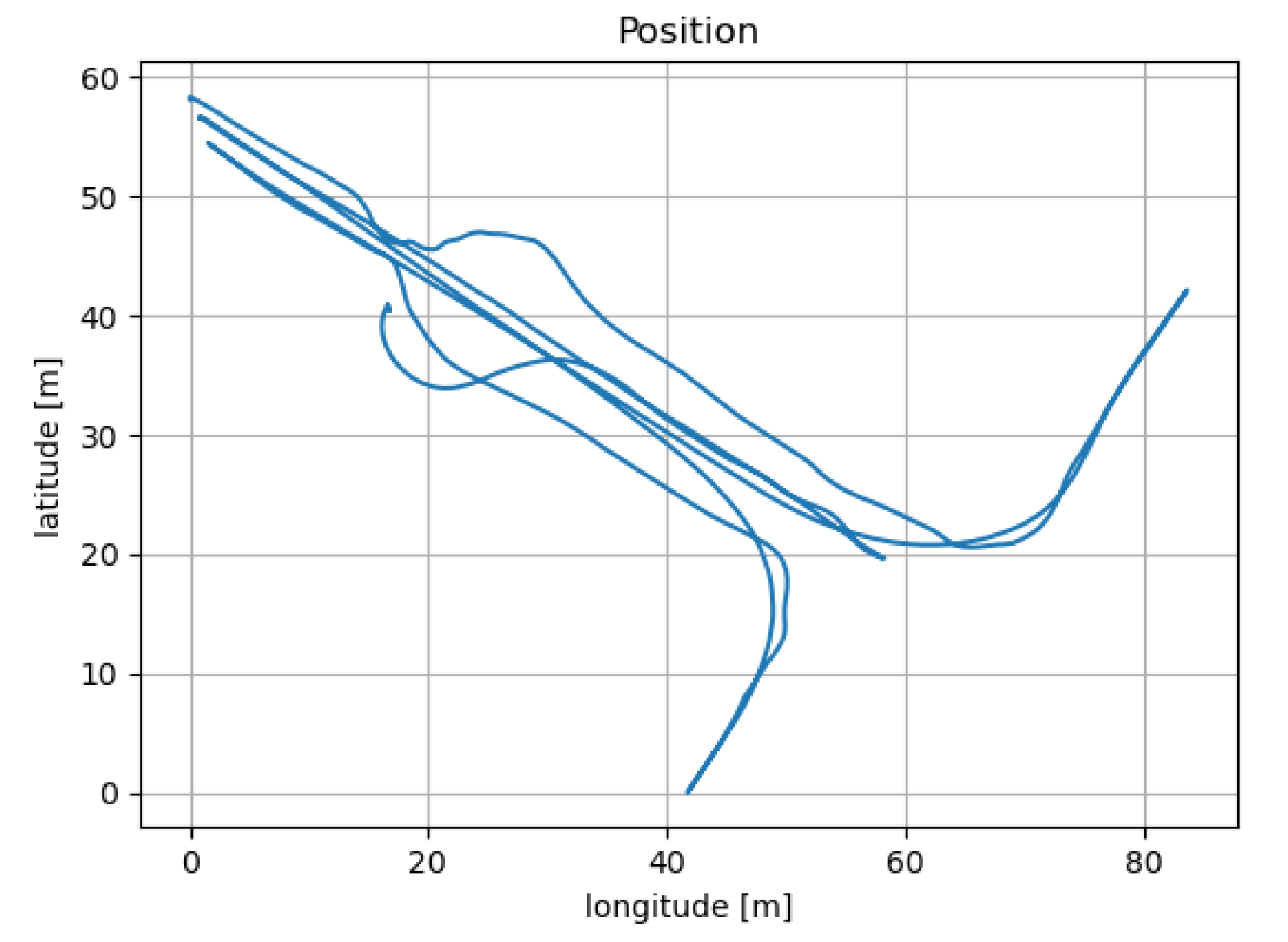
Figure 8.
Logical scenario with possible geometrical parameter distributions.
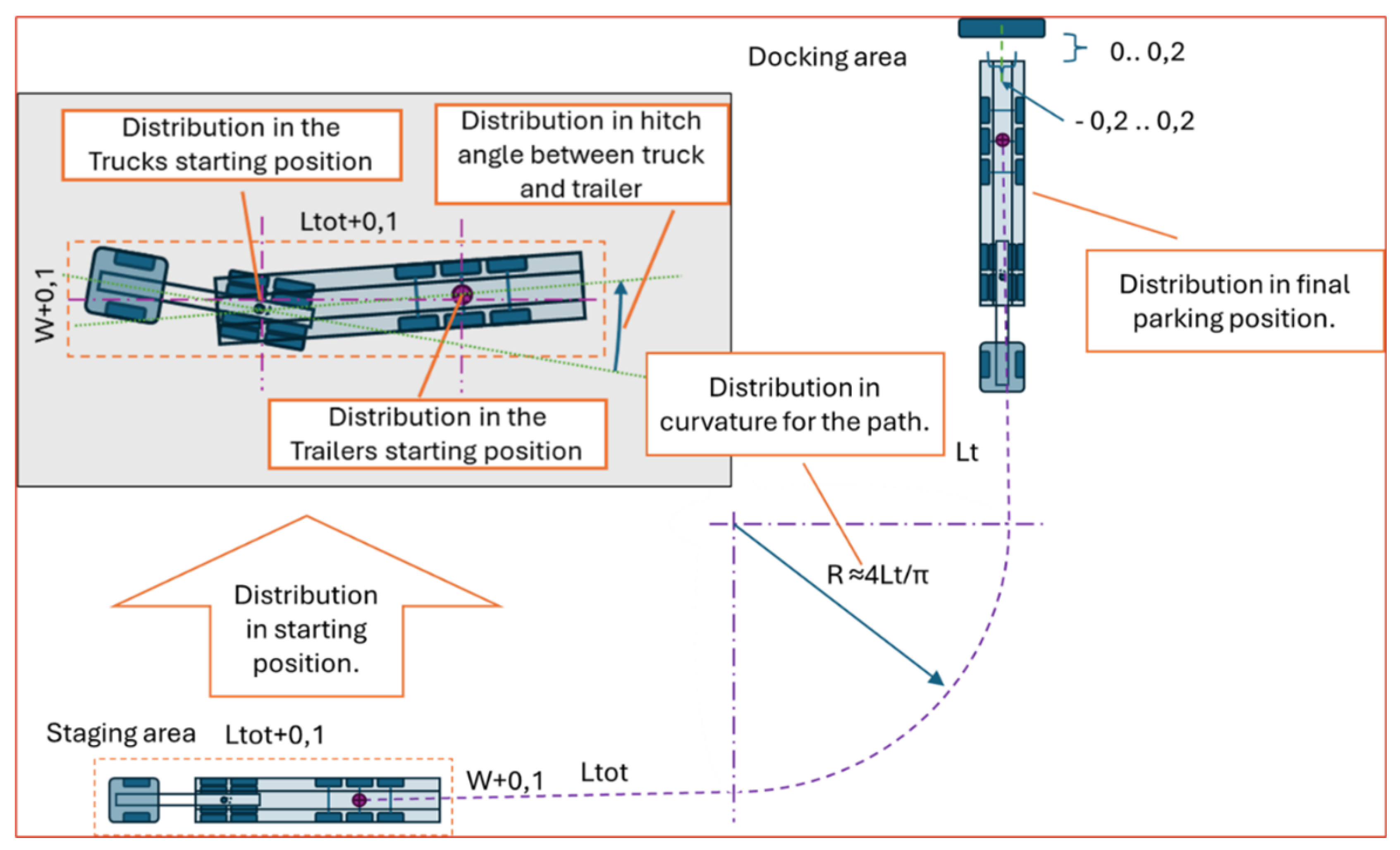
Figure 9.
Edge-case starting positions in the staging area.
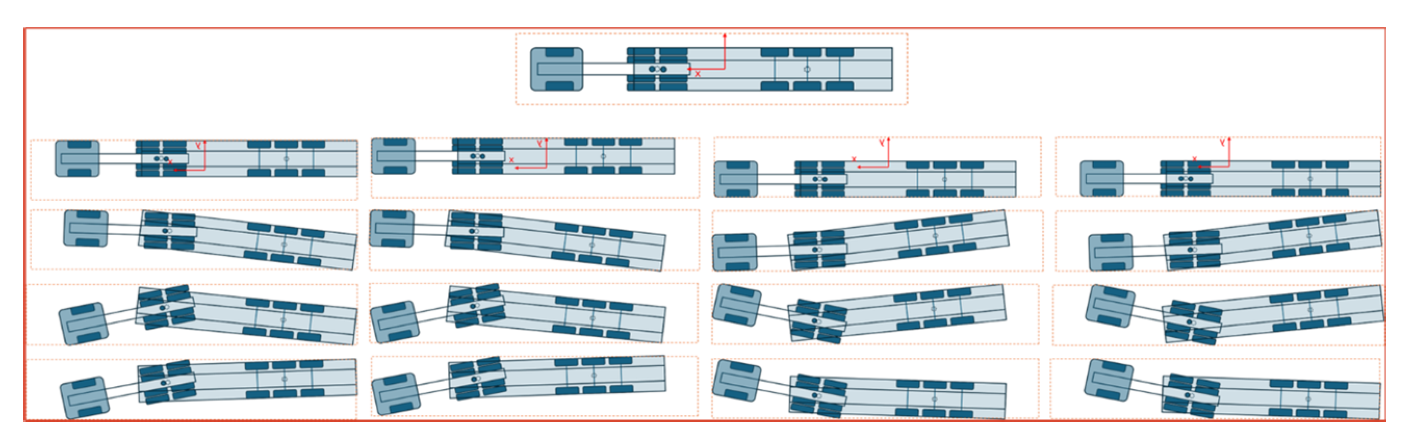
Figure 10.
Illustration of the WayWiseR test execution framework, showing its building blocks and control flow for unified physical and virtual testing.
Figure 10.
Illustration of the WayWiseR test execution framework, showing its building blocks and control flow for unified physical and virtual testing.
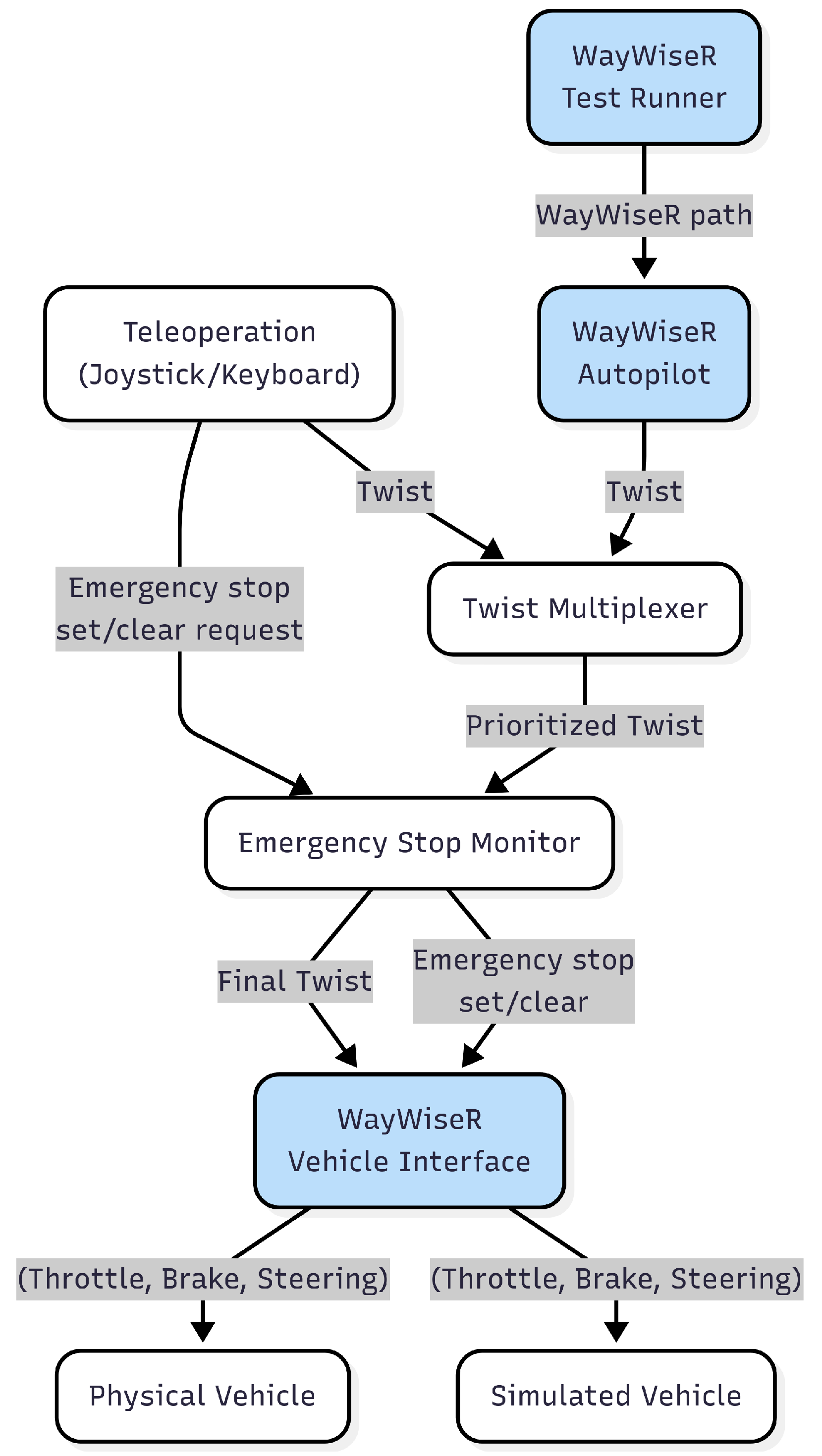
Figure 11.
Monte-Carlo simulation of the trajectories for the rear wheel axis of the truck, respectively, semi-trailer using the Python model. Rather large limits for the staging area is assumed
Figure 11.
Monte-Carlo simulation of the trajectories for the rear wheel axis of the truck, respectively, semi-trailer using the Python model. Rather large limits for the staging area is assumed
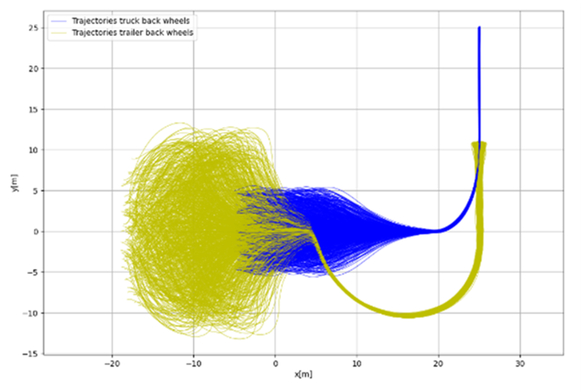
Figure 12.
Reverse parking manoeuvrer executed in the customized CARLA v0.9.15 environment using the WayWiseR autopilot. The left panel shows the RViz visualization of vehicle state and scenario elements, while the right panel displays the CARLA simulation with the Scania R620 truck and semi-trailer.
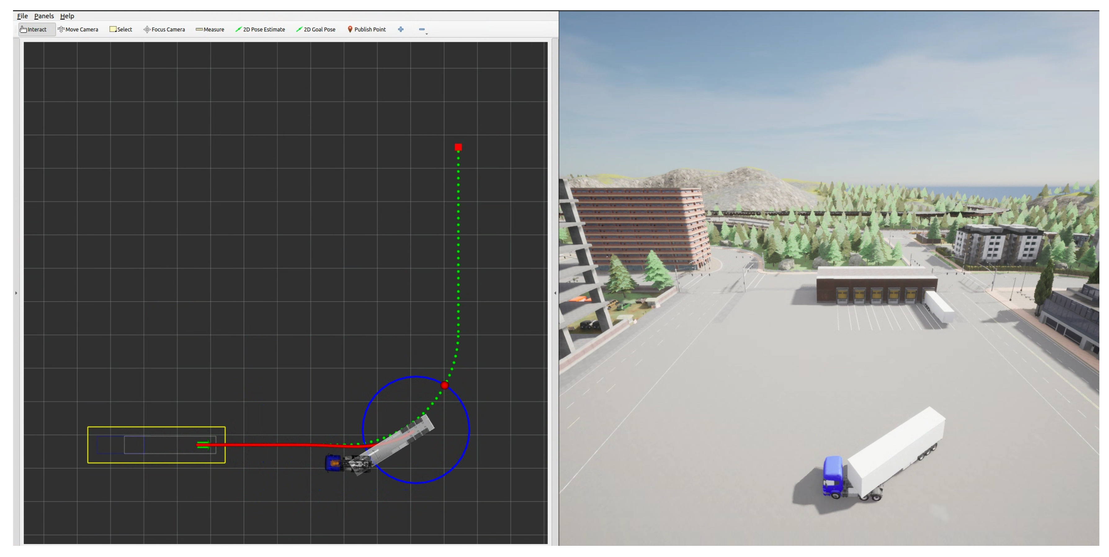
Figure 13.
Schematics of the physical test setup for the scaled model truck.
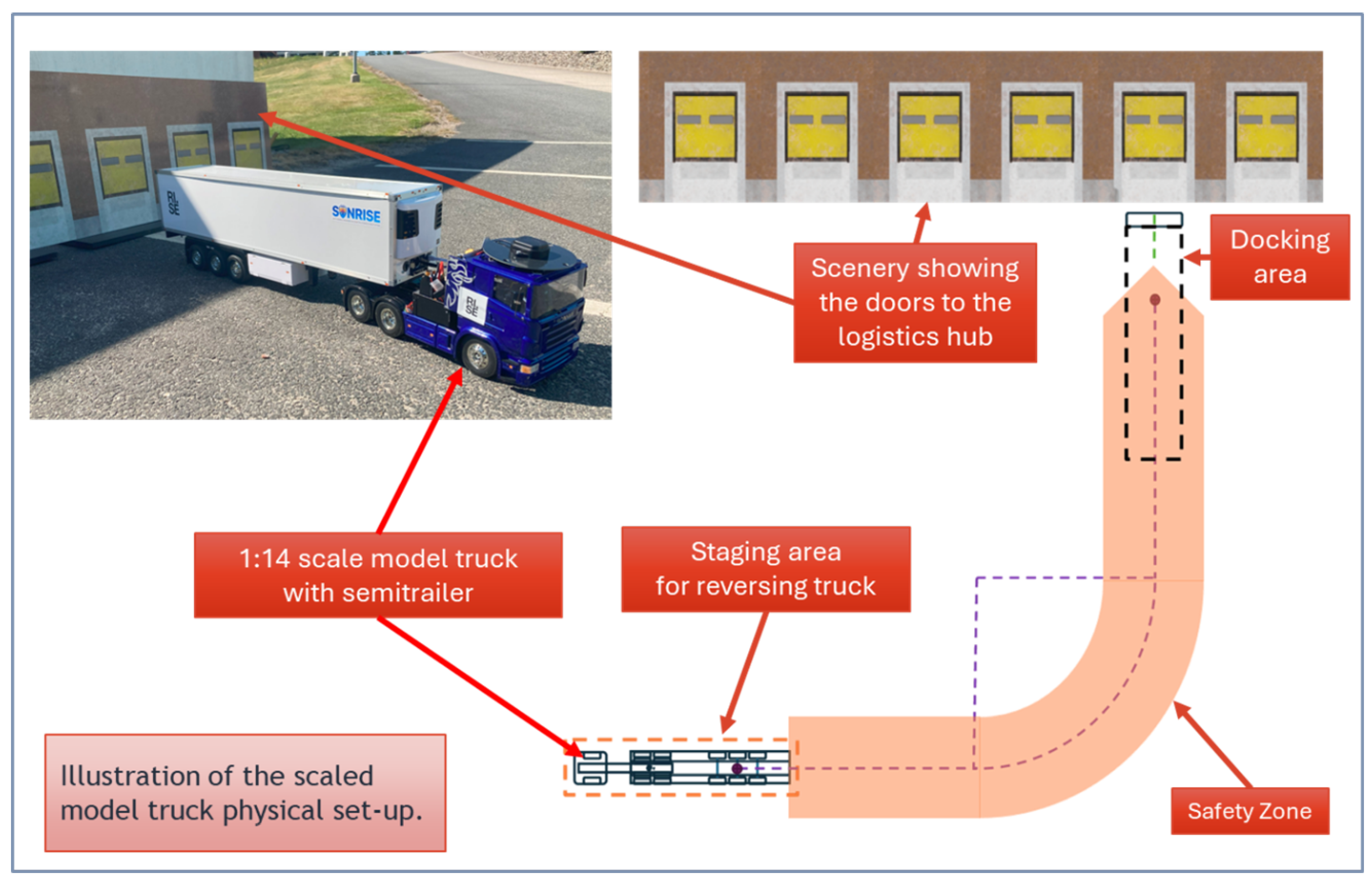
Figure 14.
Photograph of the physical test setup of the scaled model truck.
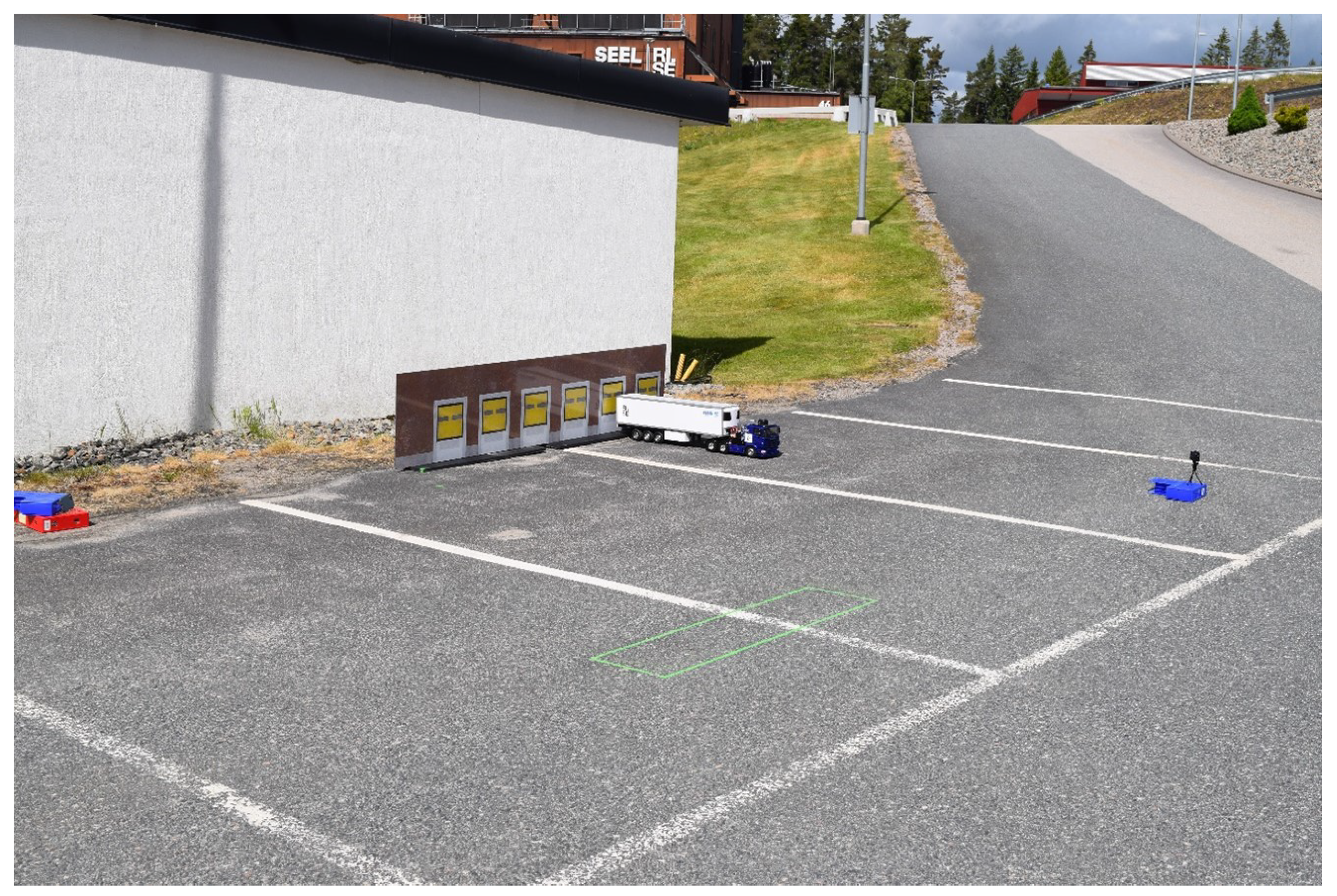
Figure 15.
Real-time view of the reversal operation in ROS2 RViz.
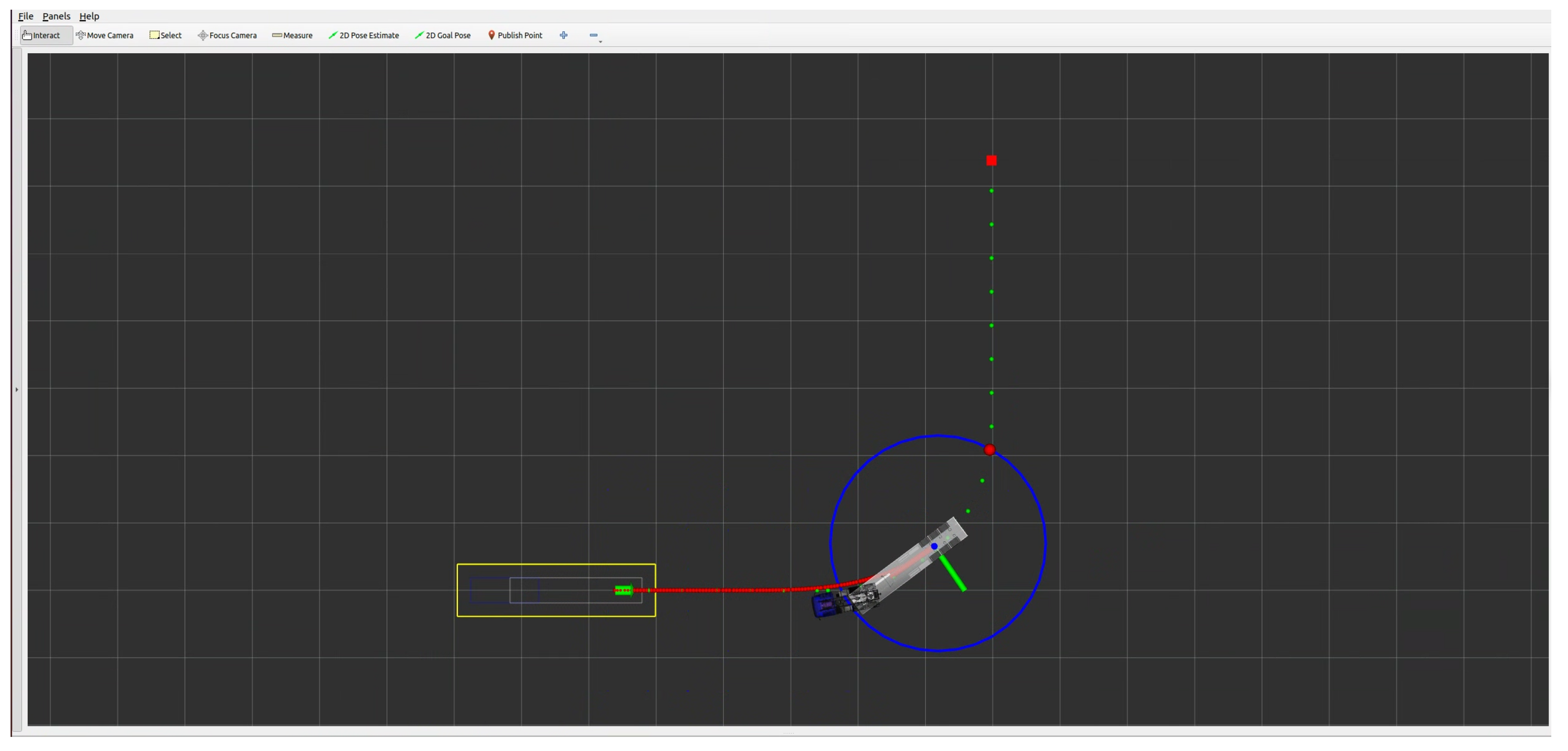
Figure 16.
The scaled model truck parked in the staging area.
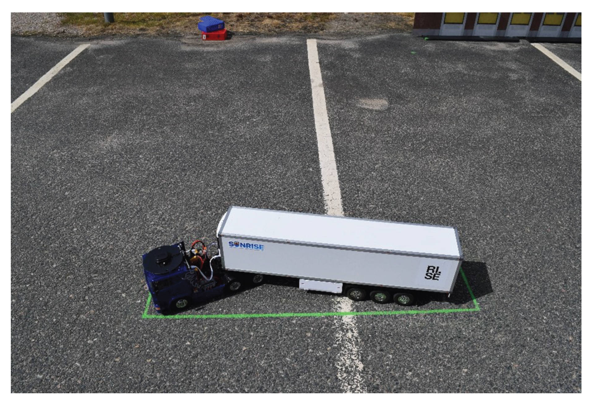
Figure 17.
Plots of the semitrailer’s rear-axle middle positions starting from the nominal starting position in the middle of the staging area. The red line/dots show the requested trajectory.
Figure 17.
Plots of the semitrailer’s rear-axle middle positions starting from the nominal starting position in the middle of the staging area. The red line/dots show the requested trajectory.
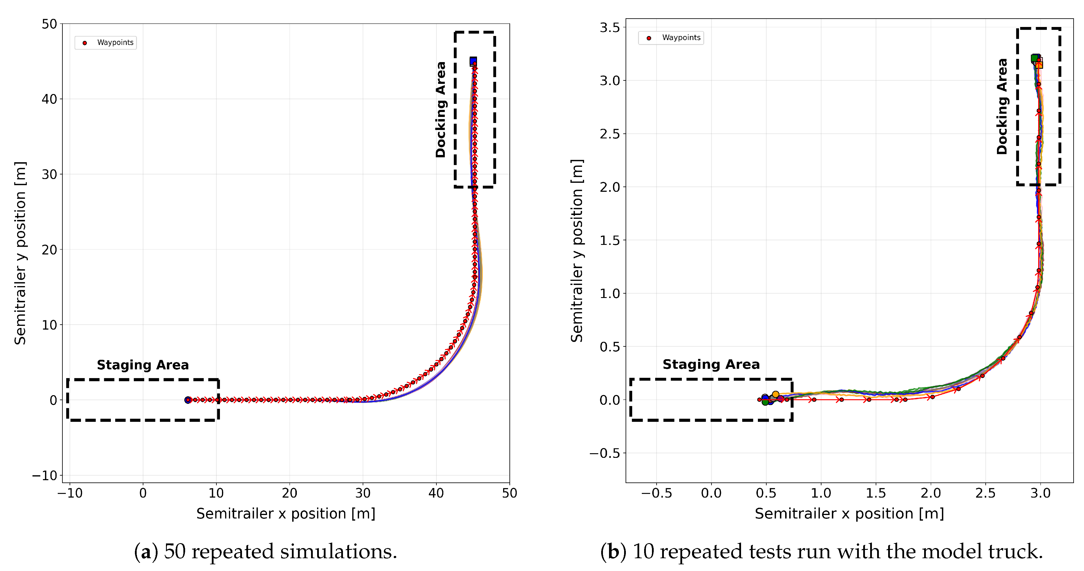
Figure 18.
Plots of the semitrailer’s docking precision, computed as the difference between the last planned waypoint and the final stopping position of the semitrailer across multiple runs.
Figure 18.
Plots of the semitrailer’s docking precision, computed as the difference between the last planned waypoint and the final stopping position of the semitrailer across multiple runs.
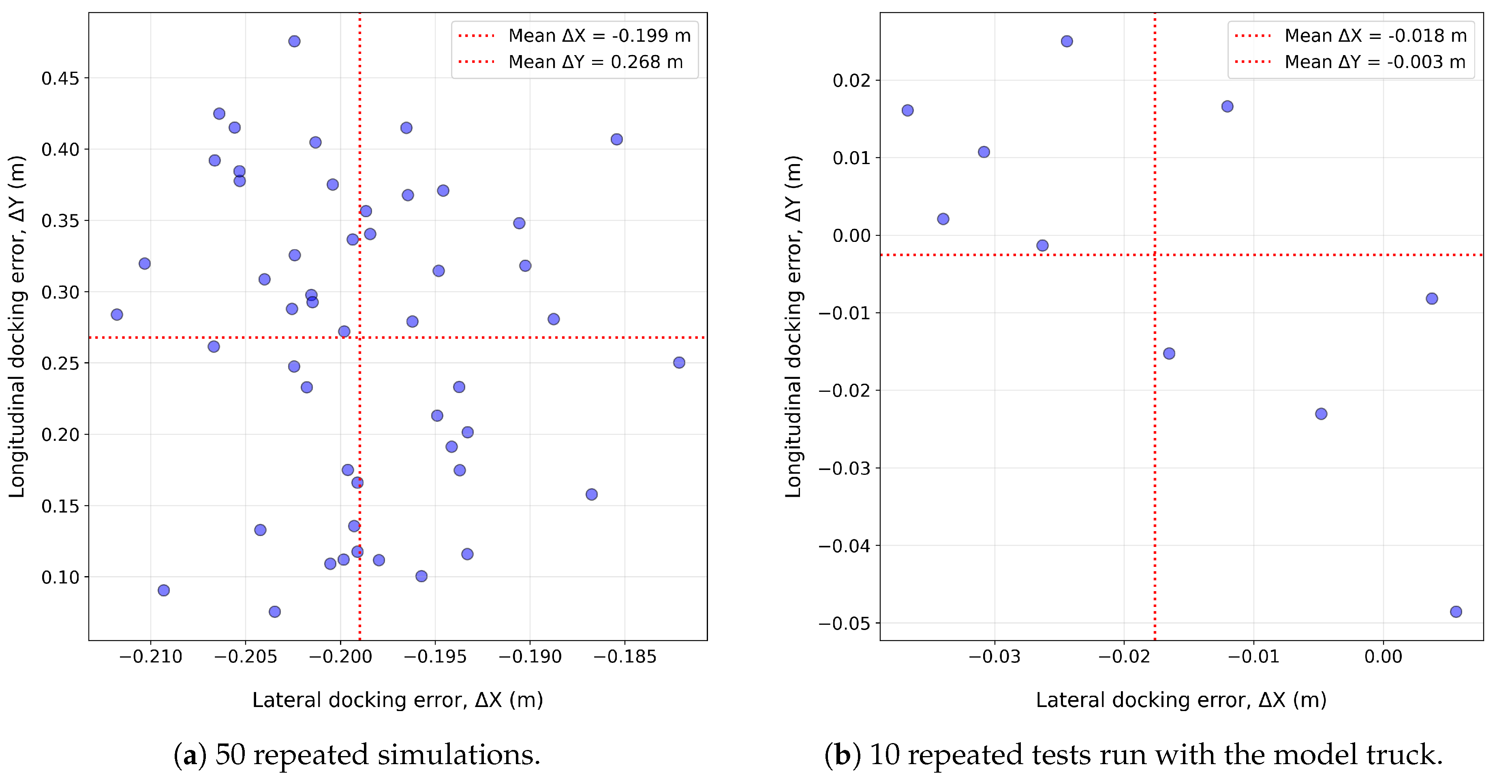
Figure 19.
Plots of the semitrailer’s rear-axle middle positions starting from distributed starting positions across the staging area. The red line/dots show the requested trajectory.l
Figure 19.
Plots of the semitrailer’s rear-axle middle positions starting from distributed starting positions across the staging area. The red line/dots show the requested trajectory.l
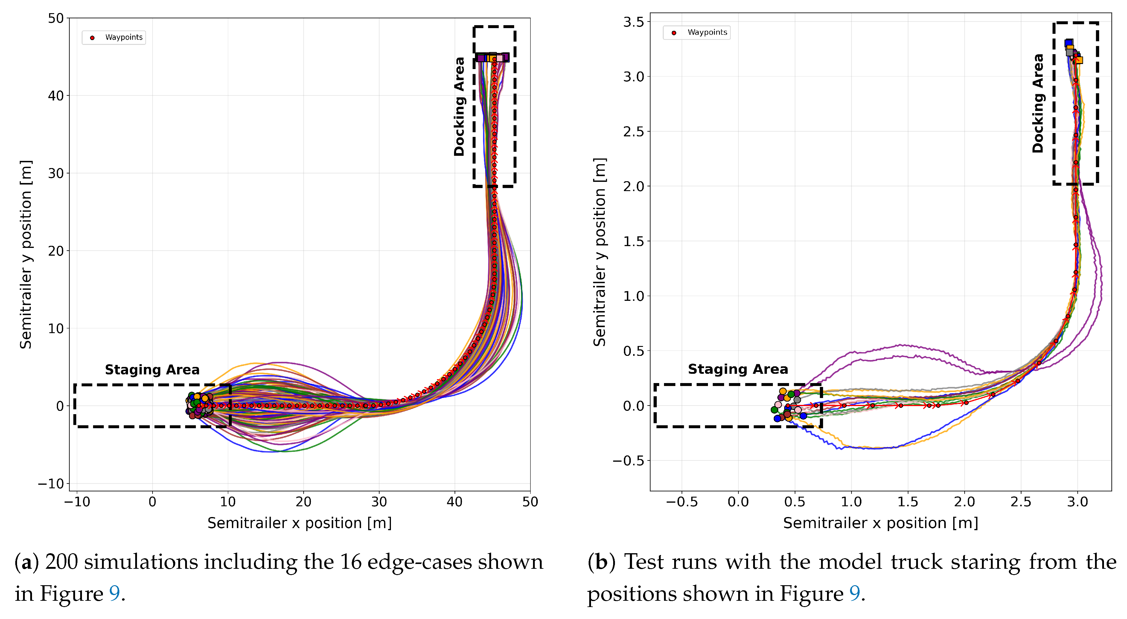
Figure 20.
Plots of the deviations of the semitrailer’s rear-axle middle positions from the planned trajectory (flattened for visualization) from start to end.
Figure 20.
Plots of the deviations of the semitrailer’s rear-axle middle positions from the planned trajectory (flattened for visualization) from start to end.
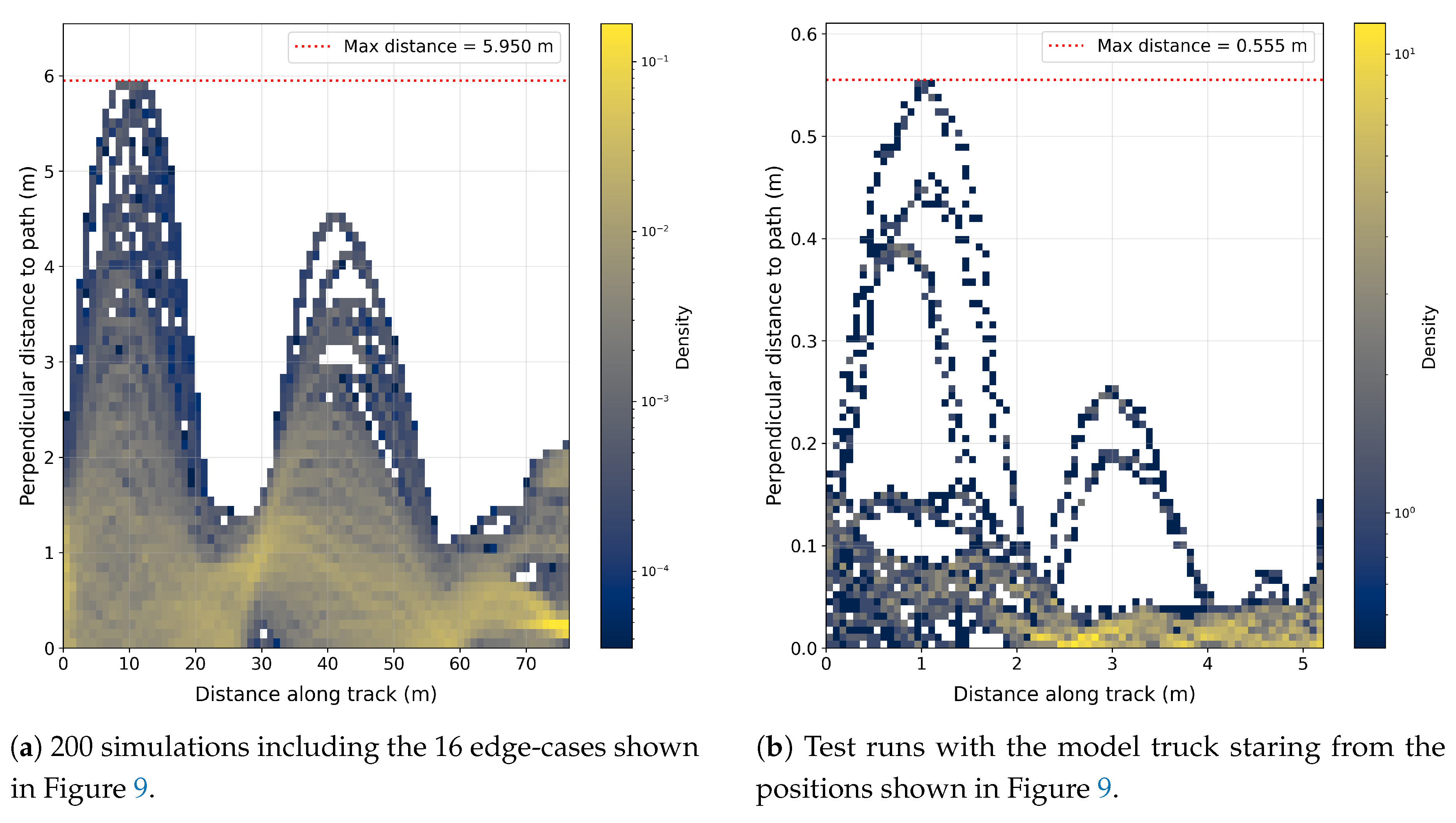

Table 1.
Docking error statistics for the semitrailer in simulation and real truck tests. denotes lateral docking error and denotes longitudinal docking error. All values are in meters.
Table 1.
Docking error statistics for the semitrailer in simulation and real truck tests. denotes lateral docking error and denotes longitudinal docking error. All values are in meters.
| Environment | Metric | Mean | Min / Max | Range |
|---|---|---|---|---|
| Simulation | -0.199 | -0.212 / -0.182 | 0.03 | |
| 0.268 | 0.076 / 0.476 | 0.4 | ||
| Scaled model truck | -0.018 | -0.037 / 0.006 | 0.043 | |
| -0.003 | -0.049 / 0.025 | 0.074 |
Disclaimer/Publisher’s Note: The statements, opinions and data contained in all publications are solely those of the individual author(s) and contributor(s) and not of MDPI and/or the editor(s). MDPI and/or the editor(s) disclaim responsibility for any injury to people or property resulting from any ideas, methods, instructions or products referred to in the content. |
© 2025 by the authors. Licensee MDPI, Basel, Switzerland. This article is an open access article distributed under the terms and conditions of the Creative Commons Attribution (CC BY) license (http://creativecommons.org/licenses/by/4.0/).
Copyright: This open access article is published under a Creative Commons CC BY 4.0 license, which permit the free download, distribution, and reuse, provided that the author and preprint are cited in any reuse.


