
Submitted:
13 August 2025
Posted:
14 August 2025
You are already at the latest version
Abstract
Thanks to the capability of metasurfaces to sculpt light beams at sub wavelength scales, they provide amazing functionality that traditional lenses cannot match. Here, we have proposed and demonstrated by numerical simulation an approach to realize deflecting transmitted beams along x or y axis whose refraction angle is determined by relative displacement of two cascaded metasurfaces. The results prove that the refraction angle can be tuned precisely by the relative movement distance between the cascaded metasurfaces and the refraction angle can be changed along x axis (or y axis) by moving a metasurface along y axis (or x axis). The metasurfaces are developed using silicon nanopillars with spatially variant orientations based on Pancharatnam-Berry (PB) phase with illumination of right-handed circular polarized (RCP) light beams. The uniqueness of this metadevice with deflectable focal points may open a new avenue for imaging, optical tweezers, optical spanner and free space communication.
Keywords:
metasurfaces
; deflection
; orbit angular momentum
; vortex
Instruction
Metasurfaces, as artificially designed two-dimensional subwavelength arrays, have attracted tremendous attention since their superior capabilities to manipulate and shape the electromagnetic waves enable the creation of ultrathin and highly compact optical systems [1]. Recently, metasurfaces are widely used to modulate amplitude, phase, and polarization of the incident light [2,3,4].
Figure 1.
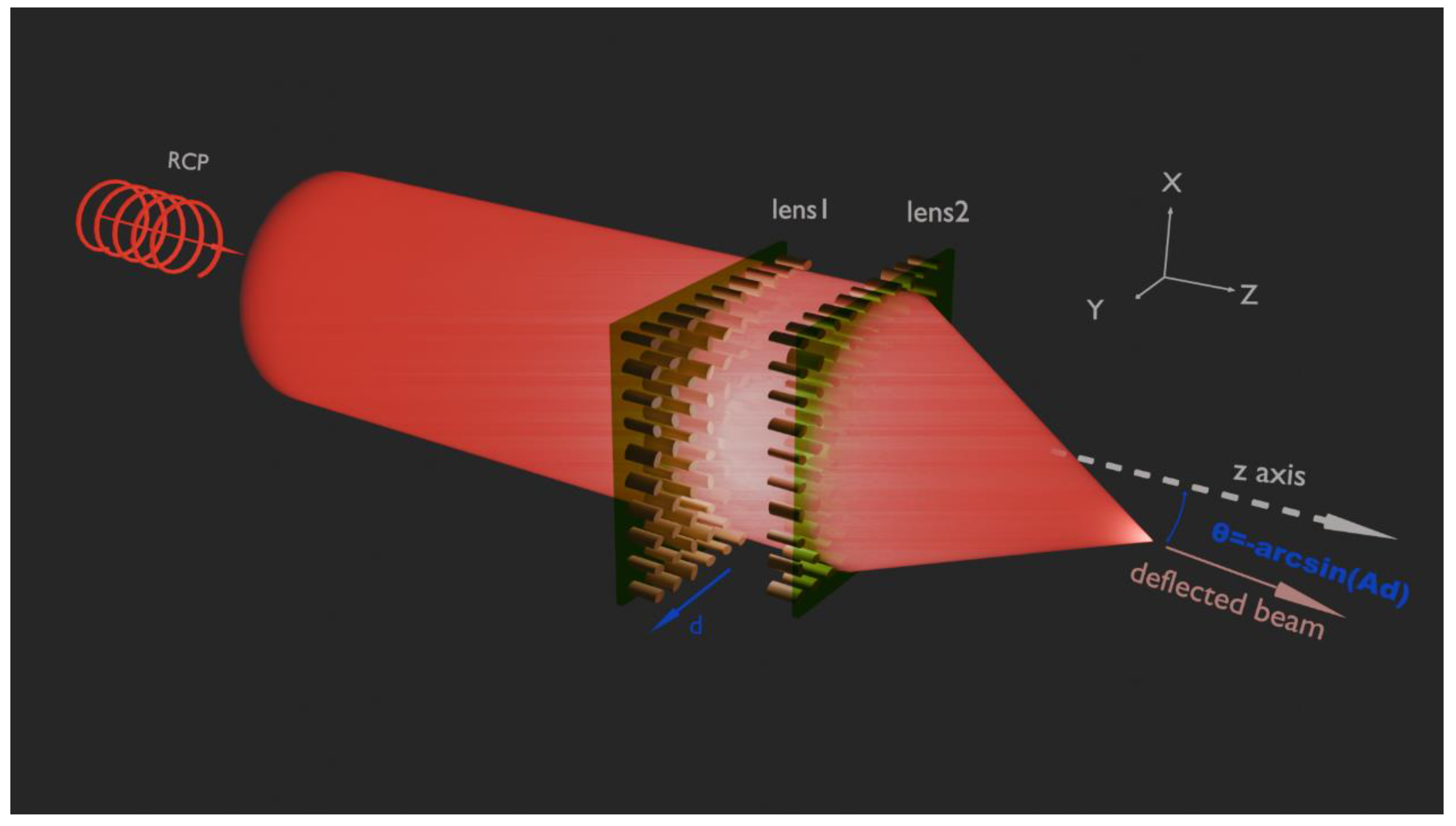
Schematic of the Alvarez metadevice with focal points of deflection. Under the illumination of RCP light beams, when lens1 moves d along x/y axis, light passing through lens2 deflects at the angle of θ=-arcsin(Ad)along y/x axis.
Figure 1.
Schematic of the Alvarez metadevice with focal points of deflection. Under the illumination of RCP light beams, when lens1 moves d along x/y axis, light passing through lens2 deflects at the angle of θ=-arcsin(Ad)along y/x axis.
Vortex beams (VBs) with orbit angular momentum (OAM) possessing nonuniform phase distributions have various applications, such as optical communication, [5] optical tweezers, [6] and spanners [7].
The early designed Alvarez metalens devices can only generate varifocal beams [8,9,10,11] and the later designed device generates beams of deflection only in x-z plane and the transmitted beams having no focus limits the application range of the transmitted beams [12]. In order to achieve complex and diverse diversification of Alvarez metalens functionalities to meet needs of the optical system, it is essential to redesign metalens devices.
Here we have proposed and investigated Alvarez metadevices, the angle of transmitted beams from which can be changed precisely by changing the relative distance between the composed two cascaded metasurfaces, which are parallel placed face to face such that one is upside down with respect to the other.
2. Principle and Theoretical Analyses
For simplicity, let us start with the metalens devices with tilted transmitted beam of a focal point, which will be extended complex ones later. The constructed phase distributions of the metasurfaces are shown in Figure 2 according to the following equation:
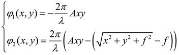 where λ, A and f denote wavelength, coefficient and focal length, respectively, x and y are the coordinates of the x and y axes.
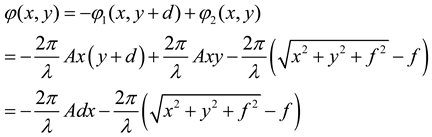
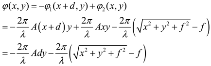
The phase of shaping beam passing through the cascaded metasurfaces can be described as equal (2) or (3).
If the first metasurface which the incident beams hit first moves along y axis, the total phase is described as
If the first metasurfaces moves along x axis, the total phase is described as
Based on Generalized Snell’s Law [1], the phases referring to deflection beams in x-z plane and y-z plane are
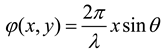
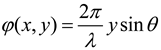
Where θ is the angle of deflection.
Compared the first term of equations (2) and (4) (or equations (3) and (5)) and letting , we can draw the conclusion that after the first metasurface moving along y(x) axis, the transmitted beam changes direction in x-z(y-z) plane and the angle of deflection is
The angles of nanopillars of the two metasurfaces are half of the phase profiles based on PB phase.
3. Results and Discussion
In this design, the finite difference time domain method is used to calculate the field distribution after the incident light passes through such metadevice consisting of 100 × 100 nanopillars (with the corresponding side length of 77.0 μm) at normal incidence. Silicon nanopillars having high refractive index and transmittance at designed wavelength of 1.55μm are placed on a glass substrate and used to modulate the phase of incident light, as shown in Figure 3. The upper surface of the nanopillar in the second metasurface the incident light passing through is set to z=0. Each nanopillar with an elliptical cross section has the same shape, with longer semimajor axis, semiminor axis, height and periodic spacing set to be 0.215 μm, 0.130 μm, 0.9 μm and 0.77μm, respectively. We set focal length and A to 50μm and 1/(20λ). The deflection angles are set to -30, -15, -5, 0, 5, 15, 30 degrees, so the corresponding moving distances of the first metasurface(d=-20λsinθ) are 15.5000, 8.0228, -2.7018, 0, 2.7018, -8.0228, -15.5000 μm respectively. RCP is chosen as incident beam for single focus and x-linear polarized light (XLP) for splitting beams.
3.1. One Focus
The intensity of transmitted beams in x-z(y=0) plane and parallel to x axis passing through points of the maximum intensity are in Figure 4.
We get the maximum intensity points of the transmitted beams, and calculate the simulated deflection angles and the relative errors with respect to the designed deflection angles.
With the designed deflection angle increases are -30, -15, -5, 0, 5, 15, 30 degrees, the maximus intensity points in x-z plane (y=0) are (-27.2,50.5), (-13.6,47.7), (-4.4,46.3), (0,46.3), (4.4,46.3), (13.2,47.7) and (27.2,50.5), respectively. The referring simulation angles are -28.3075, -15.9137, -5.4287, 0, 5.4287, 15.4683, 28.3075, and the relative errors between simulation and design are -5.64%, 6.09%, 8.57%, 0, 8.57%, 3.12% and -5.64% respectively.
We can draw the conclusion that with the absolute value of designed deflection angle increasing, the focal lengths increase slightly. The reason is that the deflection causes elongation of the focus and the amount of light passing through only metasurface increases.
As the Alvarez lens includes two cascaded metalenses and the distance between the two metalenses along the direction of beam propagation could adjustable, the simulation focus cannot accurately fall on the design point and can be movable by adjusting the position of the any of the two metasurfaces.
3.2. One Focus with Vortex
By adding the phase of vortex by rotation of the nanopillars, the transmitted beams can carry vortices. The phase of vortex has two kinds of expressions referring to plus (+) and minus (-) sign, which mean the phase vortex decreasing or increasing with the azimuth increasing [13]. In this paper, we choose plus, so the expression is as follows:
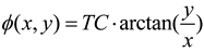
where TC is the topological, representing the number of cycles of directional variation within the range of 0 to 360 degrees, (x,y) is the nanopillar’s coordinate of a Cartesian coordinate system.
The phases of two metasurface can be described as
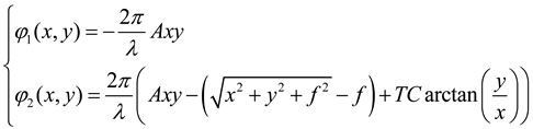
RCP of 1.55μm is selected as incident beams. The simulation results are in Figure 5.
Owing to the interference of parts of beams passing through only one metasurface, both the vortex and intensity of the transmitted beams are not symmetrical in x-z plane and the phase of vortex will have distortion in x-y plane. when designed deflection angles is not 0-degree, section and line of drawing (left part and right part of Figure 5) will not be vertical to the direction of beam propagation. As the designed deflection angle increase, the distortion gradually increases.
The areas with weak intensities in the transmitted foci are where the vortices located in x-z plane. The x-coordinates of the least intensities are -27.6, -14, -4.4, 0, 4.4, 13.6, 27.6 μm. Due to absolute angles of -30 and 30 are large, the foci deviate from y=0 plane. In this paper, we choose the plane y = 0.4 and -0.4 μm to draw right pictures for -30 and 30 degrees of Figure 5.
We choose z=50μm for ±15 and ±30 degrees of deflection angles to draw right pictures of Figure 5. We choose z = 47.7μm for 0, ±5degrees in order to get more clearly pictures.
By calculating the angles of the vortices, we get the deflection angles of transmitted beams that are -28.8987, -15.6422, -5.2702, 0, 5.2702, 15.2163 and 28.8987 degrees, respectively. The relative errors are 3.67%, 4.28%, 5.4%, 0, 5.4%, 1.44% and 3.67% respectively for -30, -15, -5, 0, 5, 15, 30 degrees of designed reflection angles.
In the above two discussion, we move the first metasurface along y axis, the transmitted beams will tilt in x-z plane. As x and y play a role of the same level, after exchanging x and y in the equation of discussion, the transmitted beams will tilt in y-z plane when moving the first metasurface along x axis.
3.3. Splitting Beams
As the nanopillars will give an additional phase to the transmitted beams which has an opposite chirality to the incident one due to geometric phase, the phase of focus referring to the left-handed circularly polarized (LCP) will have the opposite sign compared to RCP and the deflection angle of transmitted beams with LCP incident light will have the opposite sign compare to the RCP incident light. Equation (1) referring to LCP incident light should be changed as
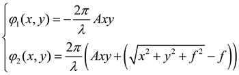
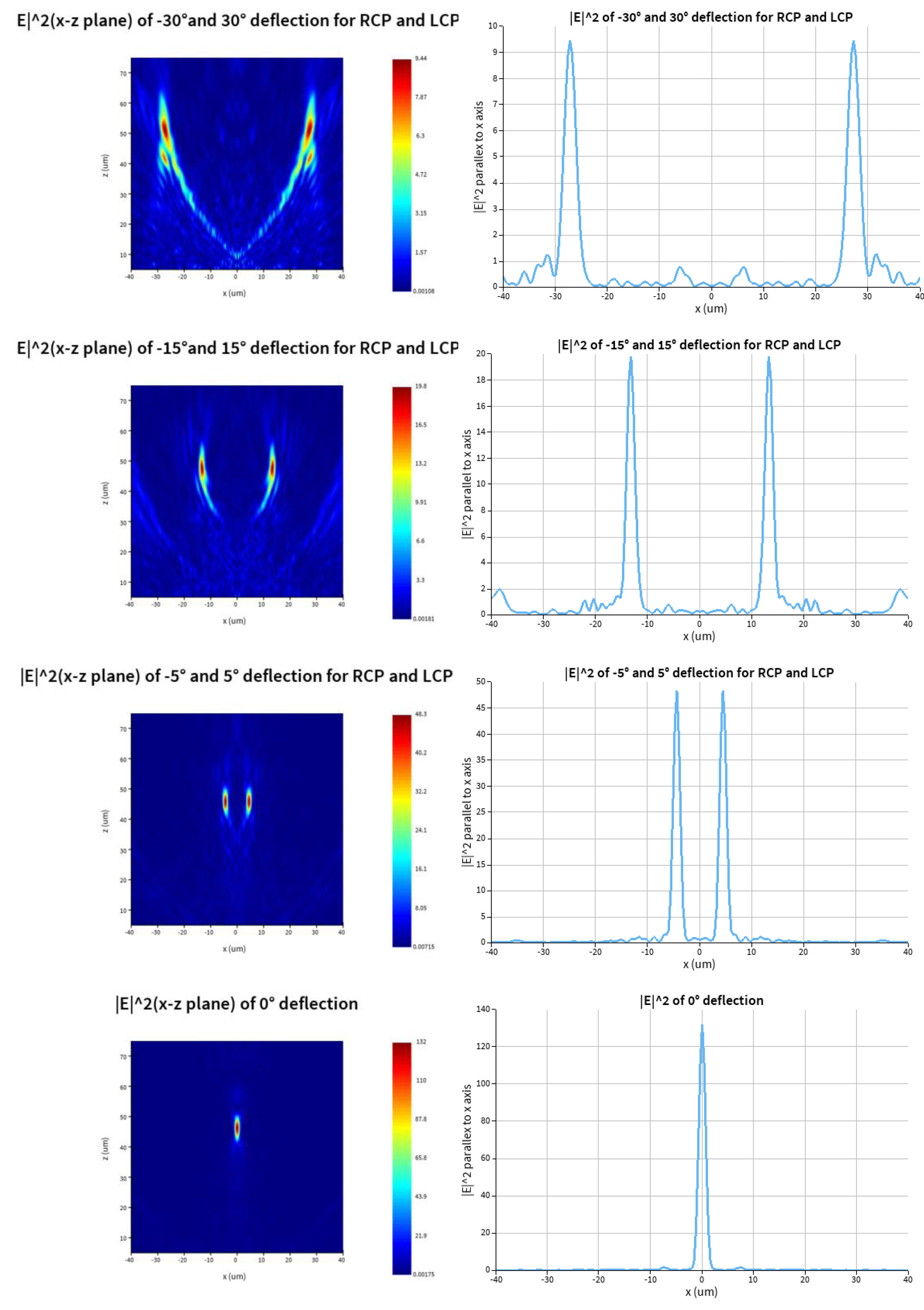
As the linearly polarized beam can be decomposed into LCP and RCP, the transmitted beams can deflect into two parts which will tilt to left and right respectively based on space multiplexing. Since the phase referring to LCP and RCP are relatively independent, we arranged the nanopillars based on space multiplexing [14]. Schematic of the metadevice with RCP and LCP focal points of deflection is in Figure 6. Compared equation (7) and (8), we can see that both LCP and RCP transmitted beams have the same phase profiles φ1 for the first metasurface and different phase profile for the second one. We select expression of φ2 from equation (7) and (8) for RCP and LCP transmitted beams respectively based on space multiplexing. The nanopillars of RCP and LCP phase profiles alternately arranged along the x-direction in the second metasurface. The simulation results for the deflection of -30, -15, 0, 15, 30 degrees for RCP (30,15,0,-15,-30 degrees for LCP) deflection beams are in Figure 7.
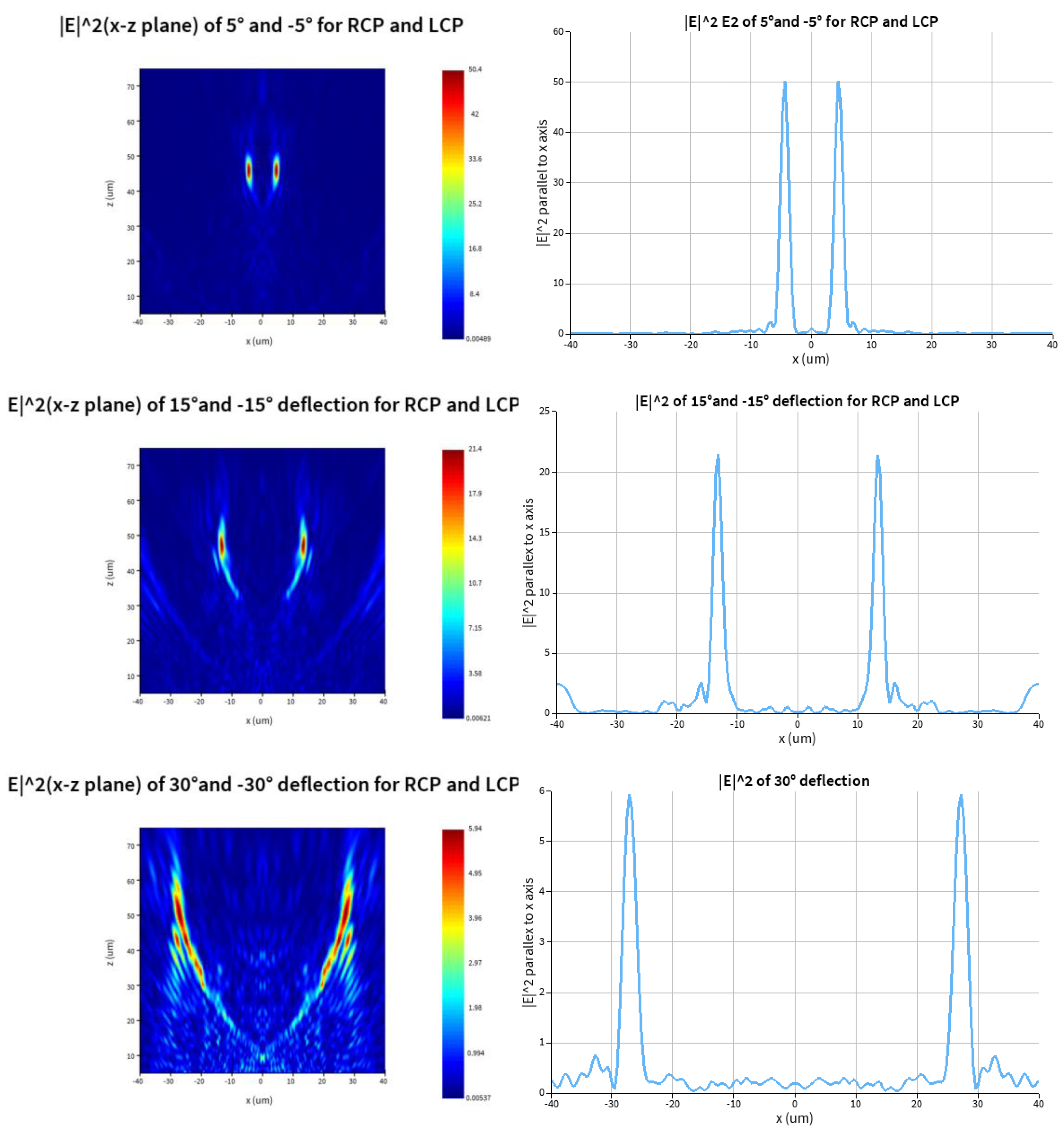
We get the points of the maximum E of the transmitted beams from left pictures of Figure 7 that are (±27.2,50.85), (±13.2,47.35), (±4.4,45.95), (0,46.30), (±4.4,45.95), (±13.2,47.00) and (±27.2,50.50) for the designed angles of -30, -15, -5, 0, 5, 15, 30 degrees, respectively. The corresponding angles and relative errors are ±28.1426, ±15.5771, ±5.4698, 0, ±5.4698, ±15.6875, ±28.3075 degrees and 6.19%, 3.85%, 9.40%, 0, 9.40%, 4.58%, -5.64% respectively. As the absolute values of ±5 degree are small, the relative errors of simulated values are larger than those of other angles.
Last but not least, the results are ones of structures of two phase profiles alternately arranged along the x-direction. As the structures of the cascaded metasurfaces are about both x and y axis symmetry respectively, there will be the same results of the structure of two phase profiles alternately arranged along the y-direction, which are confirmed in our simulations.
4. Conclusions
In conclusion, the designed metadevices could achieve all of our design goals. As the devices are designed based on PB phase, they are broadband ones. The angle of transmitted beams can be changed precisely by changing the relative distance between the two cascaded metasurfaces. The deflection direction of the transmitted beams (in x-z plane or y-z plane) also can be changed by moving direction (along y axis or axis) of the paired metasurfaces.
Both the design parameters and numerical simulations agree well with each other, except for a slight discrepancy, which can be attributed to the lower accuracy of settings in simulation.
5. Fabrication
Though we have not fabricated the metasurfaces, there are mature technologies available currently to make the metasurfaces easily by using plasma etching process and electron beam lithography technique. The simulation results perfectly meet the design expectations, so we have not made the metasurfaces and conducted experimental verification.
References
- Yu N, Genevet P, Kats M A, et al. Light propagation with phase discontinuities: generalized laws of reflection and refraction[J]. science, 2011, 334(6054): 333-337.
- 2. Xiong, B.; Liu, Y.; Xu, Y.; Deng, L.; Cheng, C.-W.; Wang, J.-W.; RW, Peng; Lai, Y.; YM, Liu; Wang, M. Breaking the limitation of polarization multiplexing in optical metasurface with engineered noise. Science 2023, 379 (6629), 294– 299. [CrossRef]
- Wang, X.; Wang, H.; Wang, J. L.; Liu, X.; Hao, H.; Tan, Y.; Zhang, Y.; Zhang, H.; Ding, X.; Zhao, W.; Wang, Y.; Lu, Z.; Liu, J.; Yang, J. K. W.; Tan, J.; Li, H.; Qiu, C.; Hu, G.; Ding, X. Single-shot isotropic differential interference contrast microscopy. Nat. Commun. 2023, 14, 2063. [CrossRef]
- 4. Su, X.; Ouyang, C.; Xu, N.; Cao, W.; Wei, X.; Song, G.; Gu, J.; Tian, Z.; O’Hara, J. F.; Han, J.; Zhang, W. Active metasurface terahertz deflector with phase discontinuities. Opt. Express 2015, 23 (21), 27152– 27158. [CrossRef]
- E. Willner, H. Huang, Y. Yan, Y. Ren, N. Ahmed, G. Xie, C. Bao, L. Li, Y. Cao, Z. Zhao, J. Wang, M. P. J. Lavery, M. Tur, S. Ramachandran, A. F. Molisch, N. Ashrafi, and S. Ashrafi, “Optical communications using orbital angular momentum beams,” Adv. Opt. Photonics 7(1), 66–106 (2015).
- K. T. Gahagan and G. A. Swartzlander, “Optical vortex trapping of particles’,” Opt. Lett. 21(11), 827–829 (1996).
- N. B. Simpson, K. Dholakia, L. Allen, and M. J. Padgett, “Mechanical equivalence of spin and orbital angular momentum of light: An optical spanner,” Opt. Lett. 22(1), 52–54 (1997).
- Barbero S.The Alvarez and Lohmann refractive lenses revisited[J].Optics Express, 2009, 17(11):9376-90. [CrossRef]
- Han Z, Colburn S, Majumdar A, et al. Millimeter-scale focal length tuning with MEMS-integrated meta-optics employing high-throughput fabrication[J]. Scientific Reports, 2022, 12(1): 5385.
- Grewe A, Hillenbrand M, Sinzinger S. Aberration analysis of optimized Alvarez–Lohmann lenses[J]. Applied optics, 2014, 53(31): 7498-7506.
- Khorasaninejad M, Chen W T, Devlin R C, et al. Metalenses at visible wavelengths: Diffraction-limited focusing and subwavelength resolution imaging[J]. Science, 2016, 352(6290): 1190-1194.
- Wang C, Liu S, Sun Y, et al. Tunable beam splitter using bilayer geometric metasurfaces in the visible spectrum[J]. Optics Express, 2020, 28(19): 28672-28685.
- Bo Xu. Vortex beam focusing based metacell polarization encryption.
- Li K, Guo Y, Pu M, et al. Dispersion controlling meta-lens at visible frequency[J]. Optics Express, 2017, 25(18): 21419-21427.
Figure 2.
Phase distribution of the designed metasurface. Left: phase of the first metalens in incident beams propagation. Right: phase of the second metalens in incident beams propagation.
Figure 2.
Phase distribution of the designed metasurface. Left: phase of the first metalens in incident beams propagation. Right: phase of the second metalens in incident beams propagation.
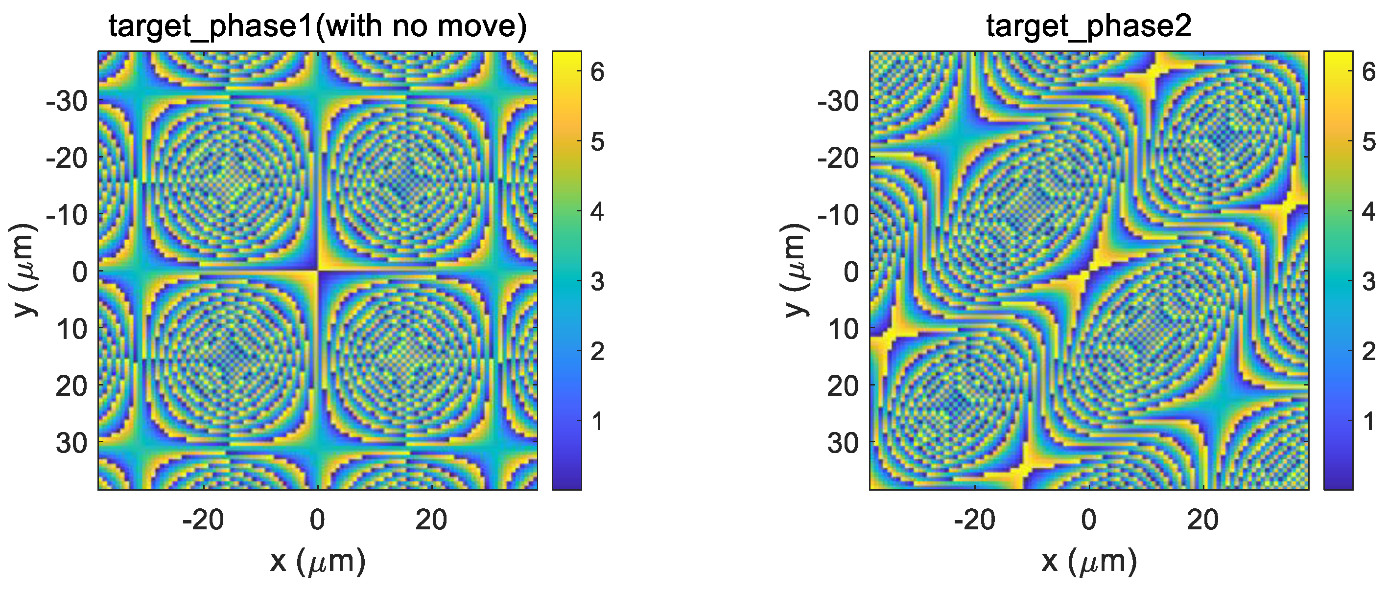
Figure 3.
Top and perspective view of the metalens unit cell formed by an elliptical nanopillar sitting on square substrate with a period Px=Py=0.77μm. The nanopillars have a fixed height of h=0.9μm, and by changing the semimajor axis(L) and semiminor axis(W), the units provide phase shifts given by jx and jy, respectively.
Figure 3.
Top and perspective view of the metalens unit cell formed by an elliptical nanopillar sitting on square substrate with a period Px=Py=0.77μm. The nanopillars have a fixed height of h=0.9μm, and by changing the semimajor axis(L) and semiminor axis(W), the units provide phase shifts given by jx and jy, respectively.
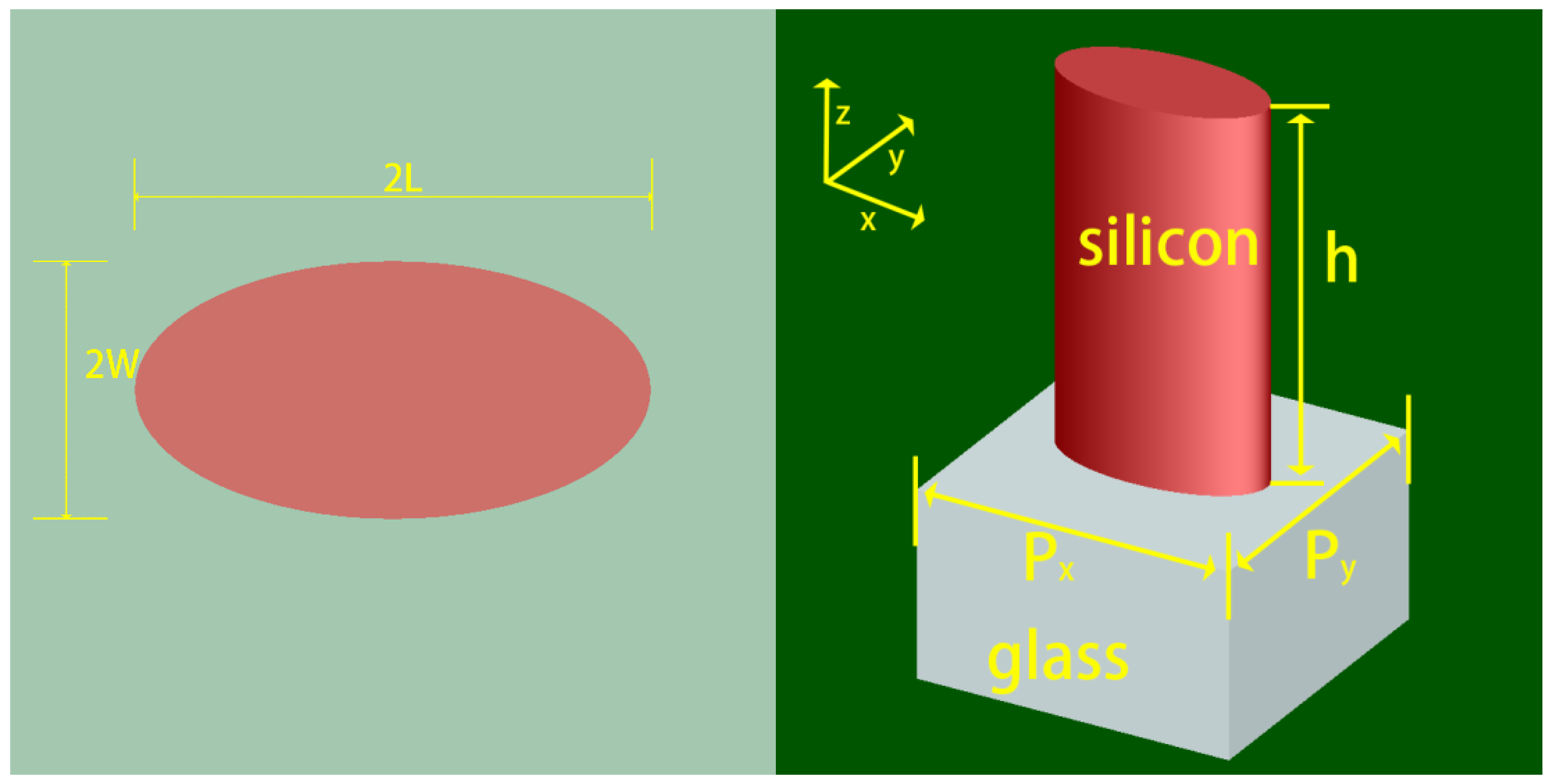
Figure 4.
The results of simulation for transmitted beams of deflection of -30,-15,-5,0,5,15,30 degrees with incident beam of 1.55μm RCP. Left: intensity of transmitted beams in x-z plane. Right: intensity of of transmitted beams parallel to the x axis passing through the point of maximum light intensity.
Figure 4.
The results of simulation for transmitted beams of deflection of -30,-15,-5,0,5,15,30 degrees with incident beam of 1.55μm RCP. Left: intensity of transmitted beams in x-z plane. Right: intensity of of transmitted beams parallel to the x axis passing through the point of maximum light intensity.
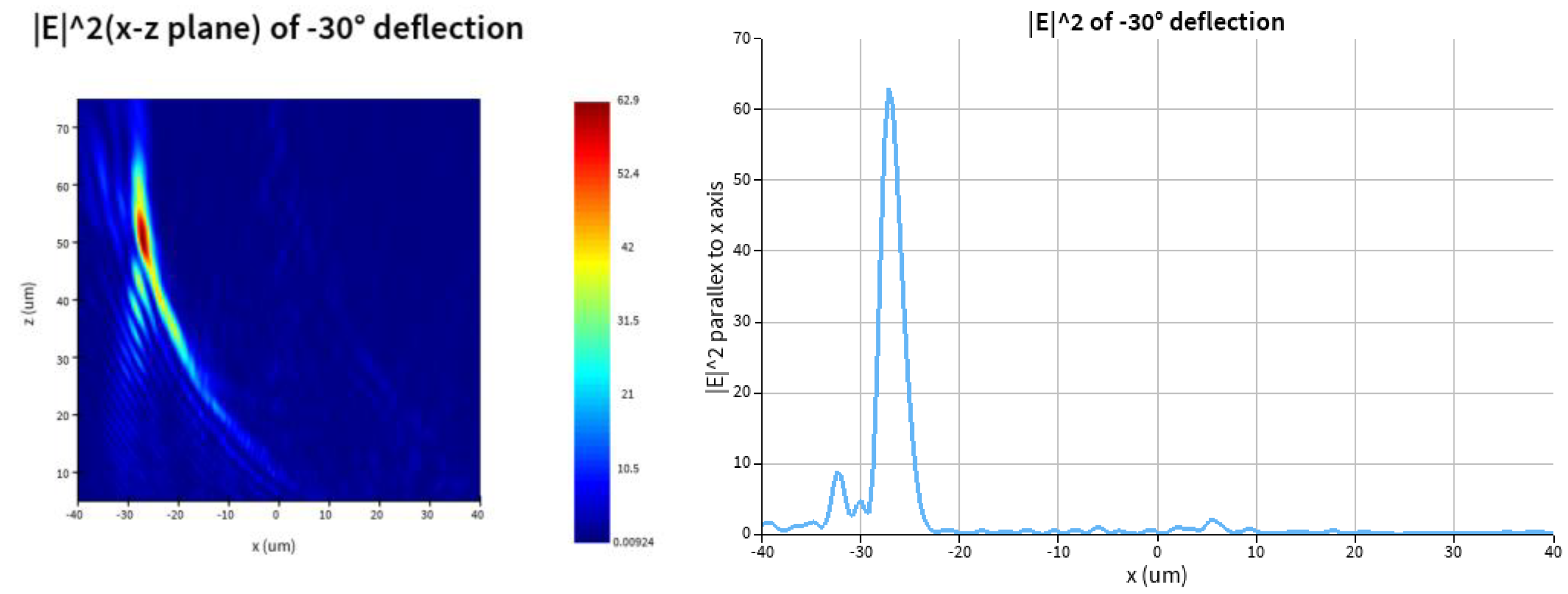
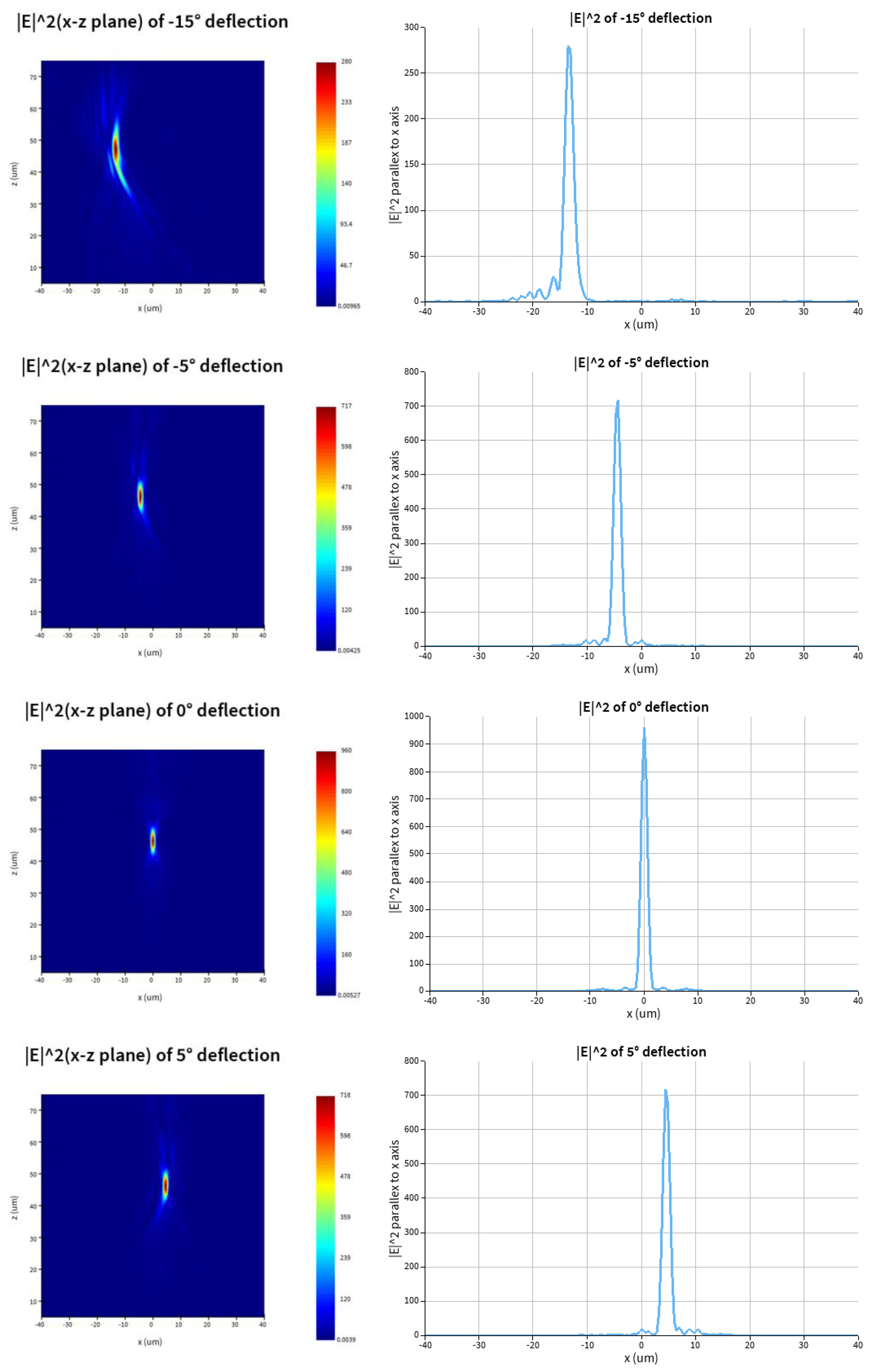
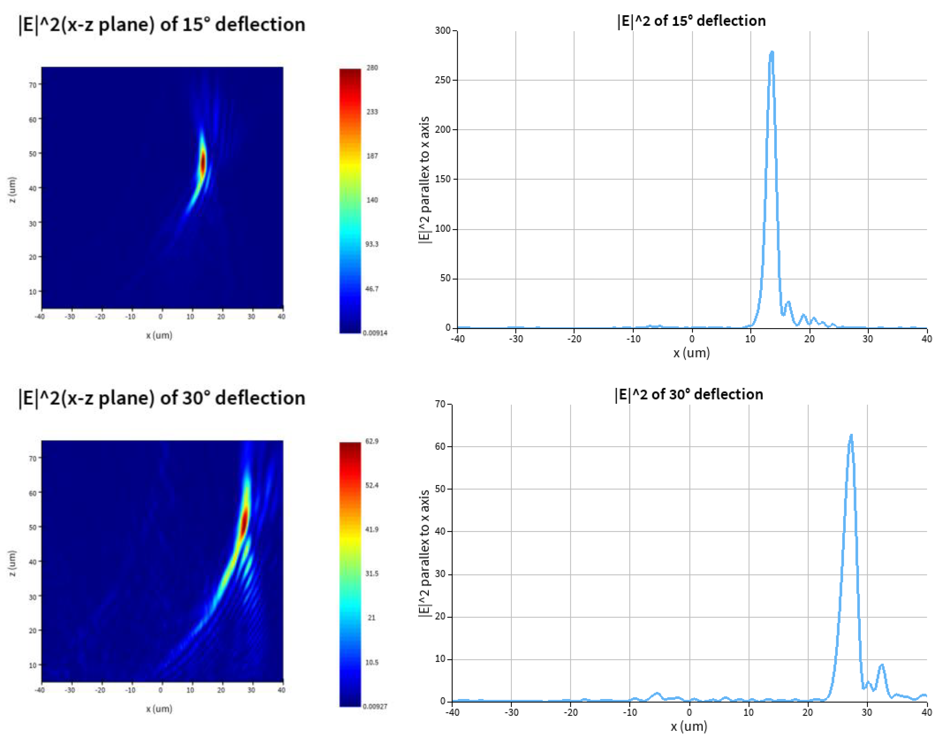
Figure 5.
The results of simulation for transmitted beams with vortex of deflection of -30,-15,-5,0,5,15,30 degrees with incident beam of 1.55μm RCP. Left: intensity of transmitted beams in x-z plane. Right: intensity of of transmitted beams parallel to the x axis.
Figure 5.
The results of simulation for transmitted beams with vortex of deflection of -30,-15,-5,0,5,15,30 degrees with incident beam of 1.55μm RCP. Left: intensity of transmitted beams in x-z plane. Right: intensity of of transmitted beams parallel to the x axis.
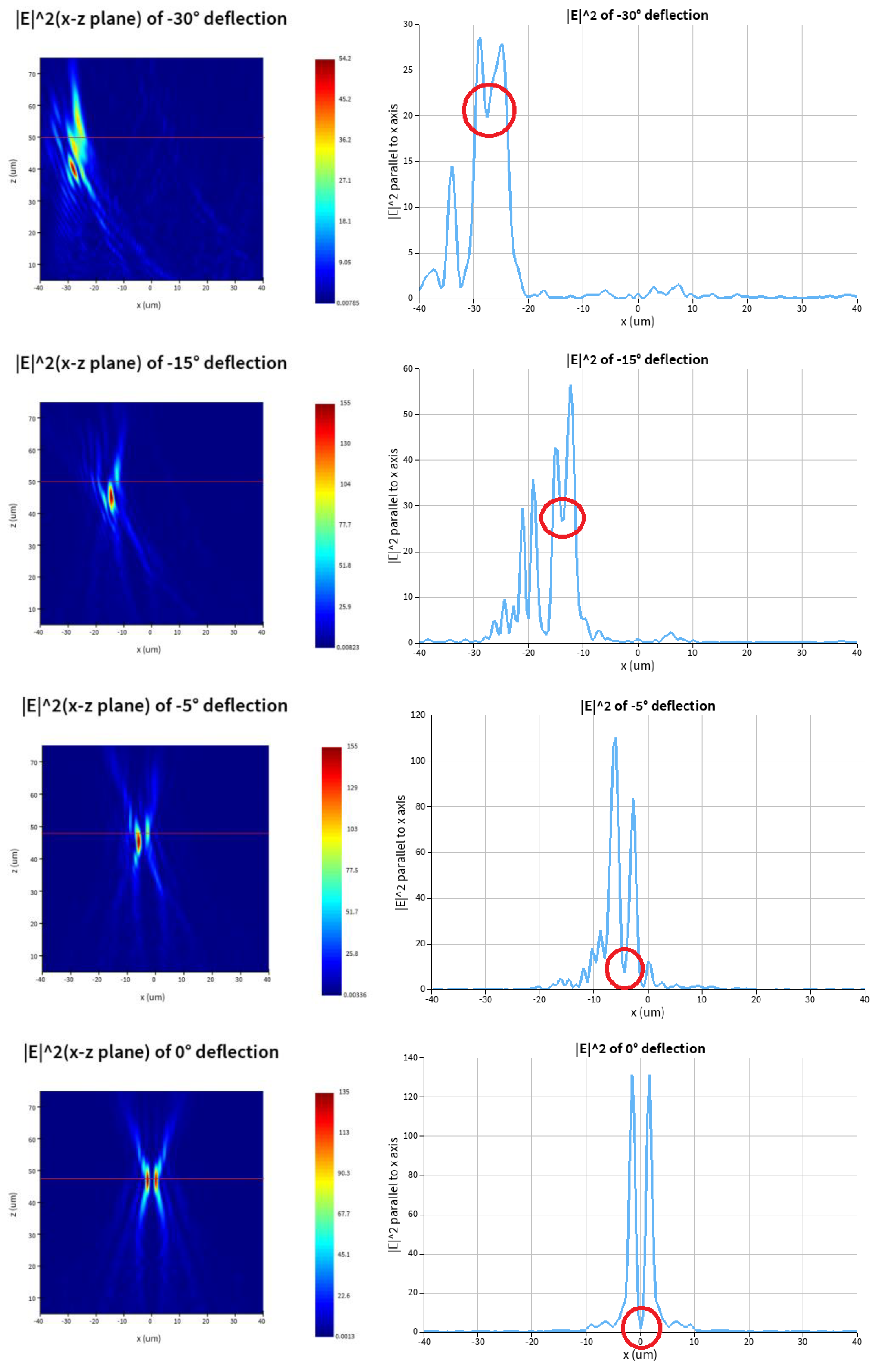
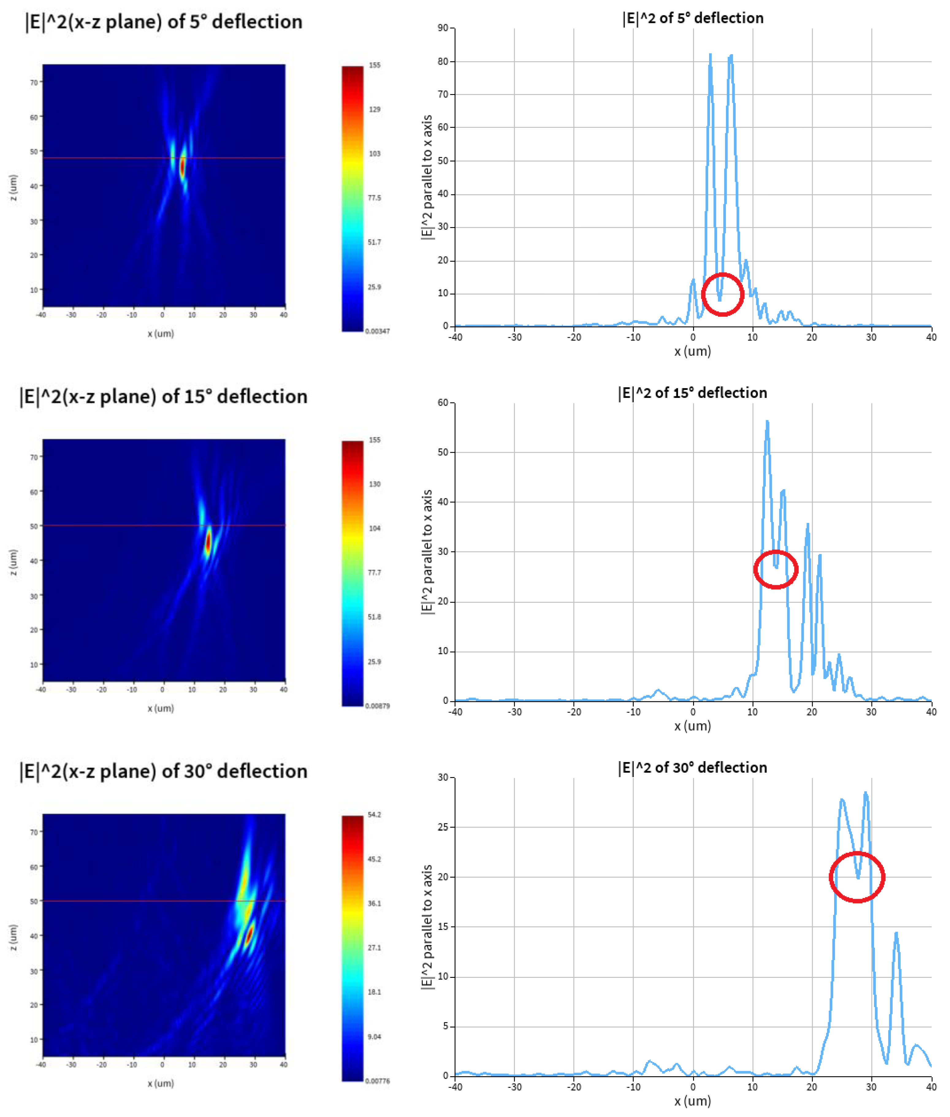
Figure 6.
Schematic of the Alvarez metadevice with focal points of deflection. Under the illumination of XLP light beams, when lens1 moves d along x/y axis, light passing through lens2 deflects at the angle of θ=±arcsin(Ad) for RCP and LCP respectively along y/x axis.
Figure 6.
Schematic of the Alvarez metadevice with focal points of deflection. Under the illumination of XLP light beams, when lens1 moves d along x/y axis, light passing through lens2 deflects at the angle of θ=±arcsin(Ad) for RCP and LCP respectively along y/x axis.
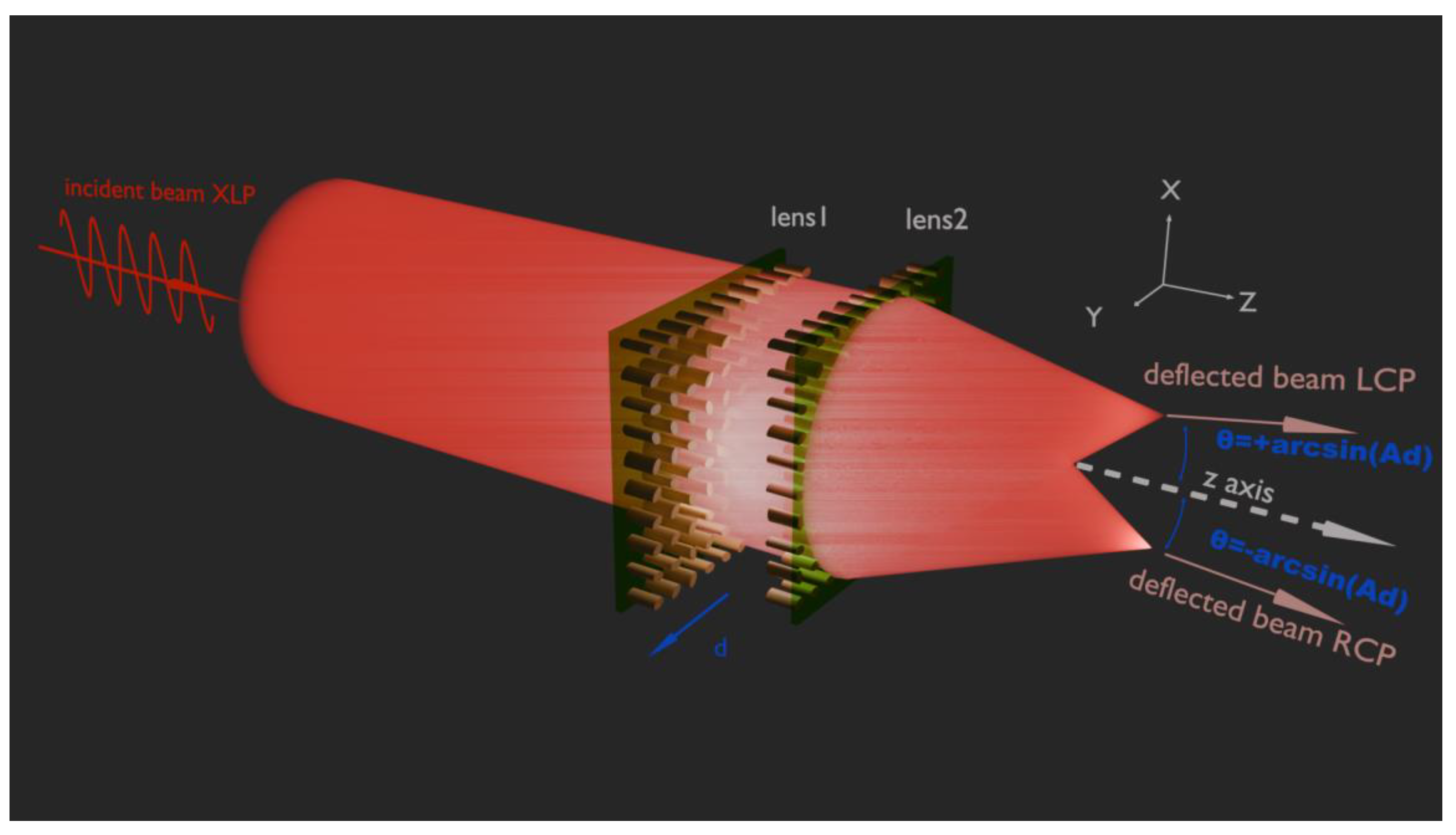
Figure 7.
Simulation results for the deflection angles of -30, -15, 0, 15, 30 degrees for RCP and 30, 15, 0, -15, -30 degrees for LCP transmitted deflection beams. Left: Intensity of E in x-z(y=0) plane. Right: Intensity of E passing through the point of the maximum light intensity parallel to the x axis.
Figure 7.
Simulation results for the deflection angles of -30, -15, 0, 15, 30 degrees for RCP and 30, 15, 0, -15, -30 degrees for LCP transmitted deflection beams. Left: Intensity of E in x-z(y=0) plane. Right: Intensity of E passing through the point of the maximum light intensity parallel to the x axis.
Disclaimer/Publisher’s Note: The statements, opinions and data contained in all publications are solely those of the individual author(s) and contributor(s) and not of MDPI and/or the editor(s). MDPI and/or the editor(s) disclaim responsibility for any injury to people or property resulting from any ideas, methods, instructions or products referred to in the content. |
© 2025 by the authors. Licensee MDPI, Basel, Switzerland. This article is an open access article distributed under the terms and conditions of the Creative Commons Attribution (CC BY) license (http://creativecommons.org/licenses/by/4.0/).
Copyright: This open access article is published under a Creative Commons CC BY 4.0 license, which permit the free download, distribution, and reuse, provided that the author and preprint are cited in any reuse.


