Submitted:
01 August 2025
Posted:
04 August 2025
You are already at the latest version
Abstract
The increasing shift from traditional energy sources to renewable energy generation has heightened the risk of frequency and voltage instability. This transition may result in serious consequences, such as significant voltage and frequency fluctuations during sudden load changes, power generation interruptions, and grid faults. One potential solution is the deployment of synchronous condensers to mitigate these issues; however, this approach may also increase operational and maintenance costs. To address this limitation, this paper proposes a method that enables renewable energy systems to emulate the sub-transient behavior of synchronous condensers, thereby enhancing local voltage and frequency stability. The proposed approach has been validated through case studies, demonstrating both its effectiveness and practicality.
Keywords:
virtual synchronous generator (VSG)
; synchronous condenser
; renewable energy
; equivalent circuit
1. Introduction
To improve the economy and environmental protection of power generation, more and more renewable energy generation equipment is being integrated into the power grid. In 2023, the installed capacity of renewable energy in China has increased 1720 million kW, accounting for 76% of the total power generation installation. In the field of renewable energy, the installed capacity of distributed photovoltaics has exceeded 129 million kW, making it an important means of power generation [1].
Most renewable energy sources are connected to the grid through inverters, and due to the significant differences in operating characteristics between inverters using traditional control methods and traditional hydro-thermal power generator sets, regions with a high proportion of new energy capacity often face frequency and voltage issues, especially under fault conditions. Regarding the frequency issue, existing literature has proposed a virtual synchronous machine control strategy to alleviate the frequency problem of new energy access by simulating the operating characteristics of synchronous machines. The concept and model of virtual synchronous generator were first proposed in references [2,3,4,5,6,7]. By simulating the rotor swing equation of synchronous generator, the inverter has the inertia operation characteristics of synchronous generator, thereby alleviating the frequency problems caused by various power disturbances. References [8,9,10,11,12] proposed the concept of adaptive virtual synchronous generator control, which automatically adjusts the virtual inertia constant and damping coefficient of the virtual synchronous machine through various adaptive algorithms to achieve the best frequency response effect. These studies have made significant progress in addressing the frequency issues arising from the integration of inverters into the power grid. However, there is little research on voltage issues under fault conditions related to virtual synchronous machines.
In the current actual power grid, in order to address the issues of reactive power and voltage under fault conditions, engineering also adopts methods such as configuring synchronous condensers to solve them [13,14,15,16,17,18]. This is because, compared to traditional power electronic reactive power compensation devices such as SVC (Static Var Compensator), the new generation condensers have better performance in severe faults, especially three-phase severe faults, and can quickly bring the voltage back to the rated value [19]. The cause of this phenomenon is due to the sub-transient effect of synchronous condensers, which can enhance the voltage support capability under fault conditions [18,19,20,21,22]. For example, in the Jiuquan-Hunan transmission sending-end power grid and the East China receiving end power grid in China, the new generation condenser has a wide range of applications, and simulation results and engineering practical phenomena also indicate that condensers have a good effect on voltage stability [13]. In areas where new energy sources such as photovoltaics are widely integrated, condensers also have a good effect on improving voltage stability. In the northwest region of China, there are many renewable energy sources such as photovoltaics and wind power connected, as well as long-distance transmission lines of 750kV. Simulation studies on this example show that condensers have the best effect on improving voltage stability in the region [14]. The study in reference [15] shows that in areas with large-scale integration of new energy, compared to centralized configuration of multiple large capacity condensers at bus stations connected to transmission lines, distributed configuration of small condensers with tens to hundreds of MVar capacity at various new energy stations can better solve the voltage stability problem under transient conditions and is more economical. However, the use of condensers also has disadvantages such as complex manufacturing processes, high maintenance costs, and loud noise. Moreover, dispersing condensers in relatively open new energy generation areas will also bring higher transportation and maintenance costs. What is more, this configuration method does not fully utilize the regulating ability of the inverter. Reference [23] discusses the performance of dynamic voltage control devices at the inverters of very weak AC power systems. The types of compensation considered are: (a) static VAr compensators (SVC); (b) synchronous compensators (SC); (c) a mix of the two; and (d) fixed capacitors. Reference [24] verified the transient reactive support capability of the new-generation synchronous condensers under grid fault condition. Reference [25] finds that superconducting synchronous condenser injects up to 45% more reactive power compared to the conventional synchronous condenser during a nearby three phase to ground fault. Reference [26] finds that synchronous condensers can provide many benefits to a power system. They have useful characteristics with regard to voltage support, especially when considering use of their short-term overload capability.
In response to the above issues, this article proposes a novel virtual condenser control (VSCon) strategy based on the equivalent circuit model of a synchronous generator [27,28,29,30,31], which can provide voltage support compared with traditional VSGs [32]. This strategy is mainly aimed at photovoltaic inverters with sufficient reactive power regulation capability at night. It can endow inverters both sub-transient reactive power response characteristics and inertia which is similar with condensers in areas where new energy is widely integrated, to enhance the transient reactive power support capability and transient voltage stability of the region. And due to the inherent decentralized nature of new energy stations, this strategy will be equivalent to distributing multiple small capacity condensers near each new energy station in the region. Therefore, it can better solve the voltage stability problem under transient conditions than centralized switching condenser, and can also reduce the transportation, maintenance costs, noise, rotational wear and other problems caused using traditional condensers to a certain extent. Moreover, compared to physical condensers that is required improvements in production processes to optimize various parameters, the virtual condenser proposed in this article only needs to adjust some control parameters, which significantly reduces costs and improves convenience while ensuring certain voltage support and frequency stability support for the power grid. At the same time, this article also analyzed the stability boundary of its key parameters based on the virtual condenser, and the results showed that reducing the sub-transient reactance of the virtual condenser would cause system instability.
The remainder of the paper is organized as follows. Section 2 proposes the control scheme of VSCon; section 3 verified VSCon’s role in voltage and frequency support and discussed the stability boundary of the system, and compare the difference between VSCon and a traditional VSG; finally, section 4 concludes the work
2. Inverters Control Equation of Virtual Synchronous Condenser
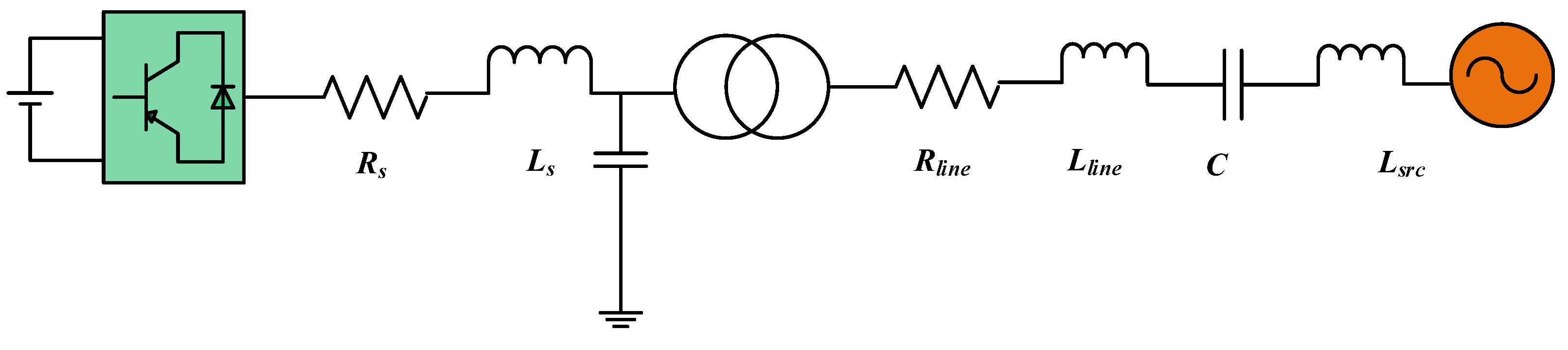
Figure 1 shows the topology of a grid-connected VSCon. To mimic condenser, it is essentially still a synchronous machine with zero active power output, so virtual condenser control essentially simulates the inverter as a synchronous generator by establishing a model of the synchronous generator. At present, research has proposed control methods that simulate inverters as synchronous generators, mostly based on simplified three-phase symmetrical round rotor synchronous machine models, while ignoring the d-axis and q-axis effects of synchronous generators. This will result in inverters being unable to have sub-transient characteristics, and therefore unable to ensure voltage stability by instantaneously generating reactive power in the event of a fault. Therefore, this article adopts a complete model of synchronous generator to enable the inverter to have the sub-transient effect of synchronous generator.
Figure 1.
Topology of grid-connected VSCon.
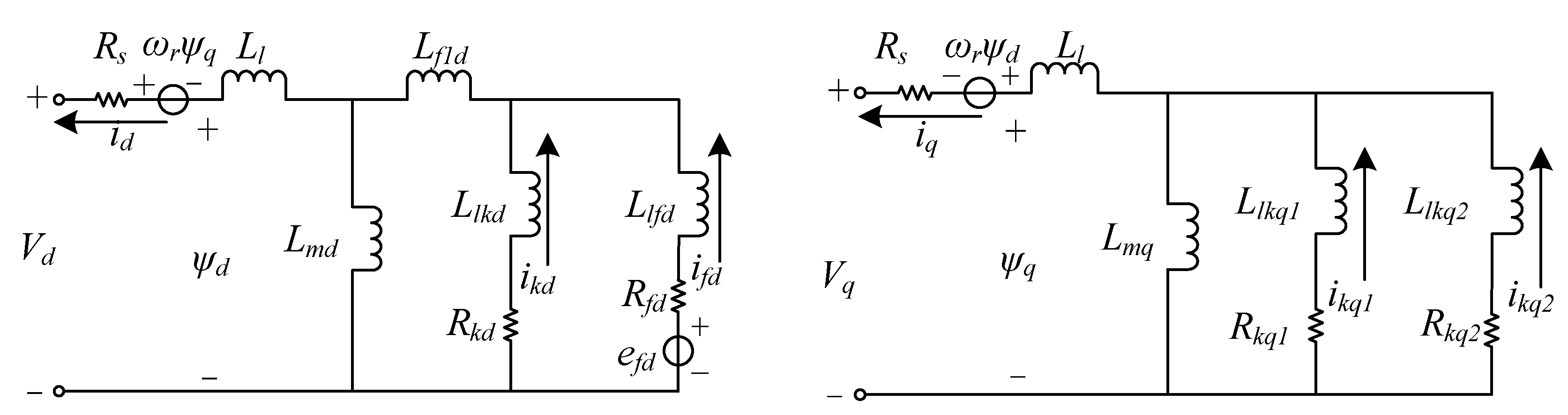
To simulate the sub-transient effects of a synchronous generator, a detailed modeling of the equivalent circuit of the synchronous generator is required first. According to [25,26], the equivalent circuit of the dq axis of a synchronous generator can be represented by Figure 2. This model requires six variables to represent the operating state of the synchronous generator, namely, armature currents id and iq, excitation branch current ifd, d-axis damping winding current ikd, and q-axis damping winding currents ikq1 and ikq2. Rs, Ll, Lmd, and Lmq are stator resistance, stator leakage inductance, and dq axis stator inductance, respectively; Llkd and Rkd are the inductance and resistance of the d-axis damping winding; Llfd and Rfd are the inductance and resistance of the excitation winding; Llkq1, Llkq2, Rkq1, Rkq2 are the inductance and resistance of the q-axis damping winding; Lf1d is called Canay inductor. The electrical equation corresponding to its equivalent circuit diagram can be expressed by equations (1) and (2) and Figure 2.
where,
Figure 2.
DQ axis equivalent circuit model of a synchronous machine.
For the time constant and transient reactance parameters of synchronous machines, they can be converted into equivalent circuit parameters using the conversion method described in [28].
Compared to the equivalent circuit equation, the mechanical equation of a synchronous generator is relatively simple and can be expressed using equations (3) to (5) and Figure 3:
Figure 3.
Mechanical model of a synchronous machine.
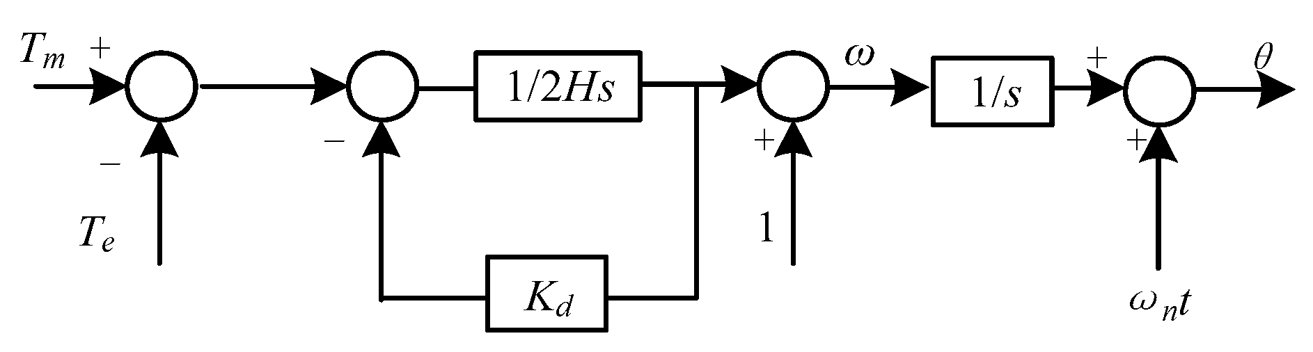
Among them, Tm is the input torque of the prime mover, Te is the electromagnetic torque, H is the inertia constant, Kd is the damping coefficient, and ωn is the rated angular velocity. Adding equivalent circuit equation and rotor equation to the control equation of the inverter can simulate the external characteristics of synchronous condenser.
According to the control method described above, it can ultimately be applied to the switch control of inverters. For an actual inverter, the resistance and inductance of its grid connection point can be equivalent to the stator resistance and inductance of a virtual condenser, while the neutral point voltage of the three bridge arms can be equivalent to the three-phase internal potential of the generator, that is:
Based on the generator equivalent circuit equation in the previous text, the final inverter PWM control strategy can be obtained, as shown in the following figure:
3. Case Study
3.1. Affect to Charactors on Faults Sub-Transient Parameters
In the system shown in Figure 4, the influence of sub-transient parameters on the characteristics under faults is studied. The parameters of the virtual condenser are shown in the Table 1 and Table 2. In actual synchronous machines, the sub-transient reactance mainly determines the characteristic of terminal voltage drop during the fault. In order to investigate whether virtual condensers have similar characteristics, corresponding research was conducted in this section. At t=0.5s, a three-phase grounding fault occurred at the outlet of the infinite bus. At t=0.575s, the fault is cleared. When the values of the transient reactance and the constant of the transient open circuit change, the corresponding terminal voltage phenomenon is shown below.
Figure 4.
Virtual Condenser Control of Inverter.
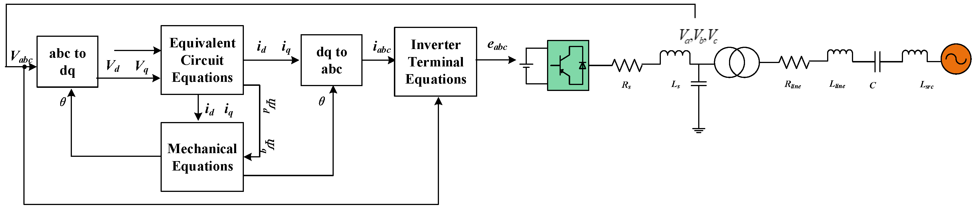

Table 1.
Base parameters of the virtual synchronous condenser.
| Parameters | Value | Parameters | Value |
| Rs | 0 | Xl | 0.13 |
| Xd | 1.79 | Xq | 1.71 |
| Xd’ | 0.169 | Xq’ | 0.228 |
| Xd” | 0.135 | Xq” | 0.2 |
| Tdo’ | 4.3s | Tqo’ | 0.85s |
| Tdo” | 0.032s | Tqo” | 0.05s |
| H | 0.868495s | Kd | 0 |
Table 2.
Base equivalent circuit parameters of the virtual synchronous condenser.
| Parameters | Value | Parameters | Value |
| Rs | 0 | Rkq2 | 0.0141 |
| Rfd | 0.0010 | Llkd | 7.3005 |
| Llfd | 0.5119 | Llkq1 | 0.0942 |
| Rkd | 0.6343 | Llkq2 | 0.3293 |
| Rkq1 | 0.0082 | Lf1d | -0.4735 |
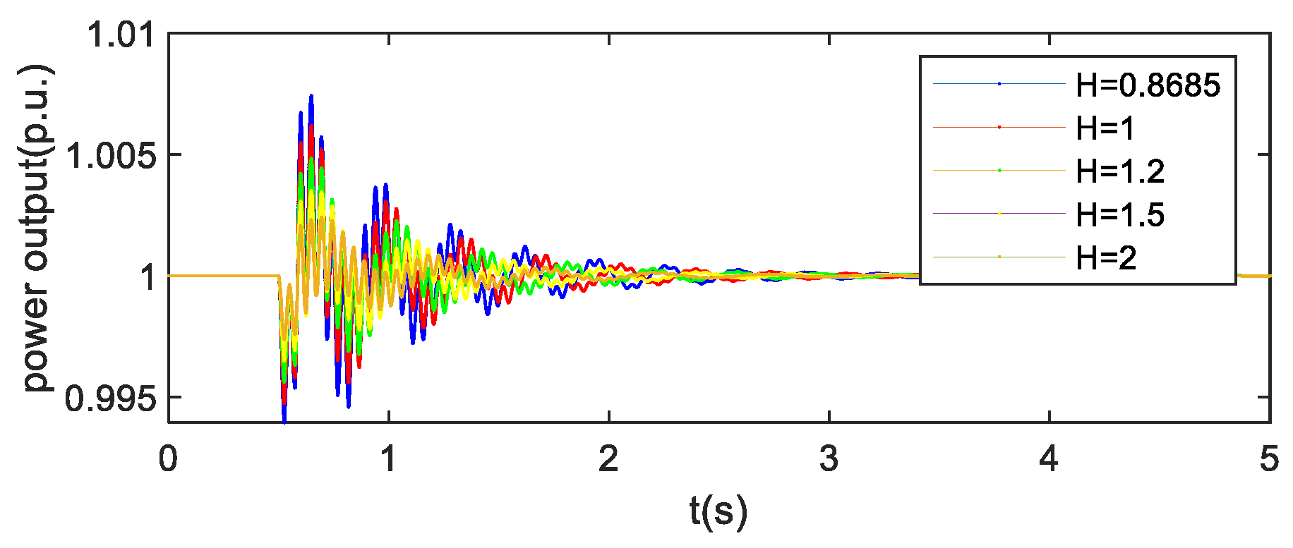
Build the simulation model of the Figure 4 in Matlab/Simulink software, where the modeling of the inverter adopts the average model [33]. The waveforms of the terminal voltage (low voltage side of the transformer) during the fault period under different transient reactance parameters are shown in Figure 5. The change in the transient reactance will not change the steady-state operating point, and when the virtual transient reactance decreases, the reactive power emitted during the fault moment and duration will significantly increase, providing strong support for the voltage; However, during a period after a fault, a smaller virtual sub-transient reactance may slow down the speed of voltage convergence. For the sub-transient open circuit constant, increasing its value has no significant effect on the voltage drop during the fault period, but can accelerate the convergence speed of the voltage. Overall, the virtual sub-transient reactance and virtual sub-transient open circuit constant are like the inertia and damping coefficients in virtual synchronous machines. Increasing the former can alleviate the frequency drop problem at the moment of fault, while increasing the latter can help accelerate the convergence speed of voltage for a period after the fault. Figure 6 and 7 show the virtual rotor speed and real power output when inertia of VSCon changes, indicating that VSCon has inertial characteristics that a traditional VSG has.
Figure 5.
Terminal voltage in p.u.
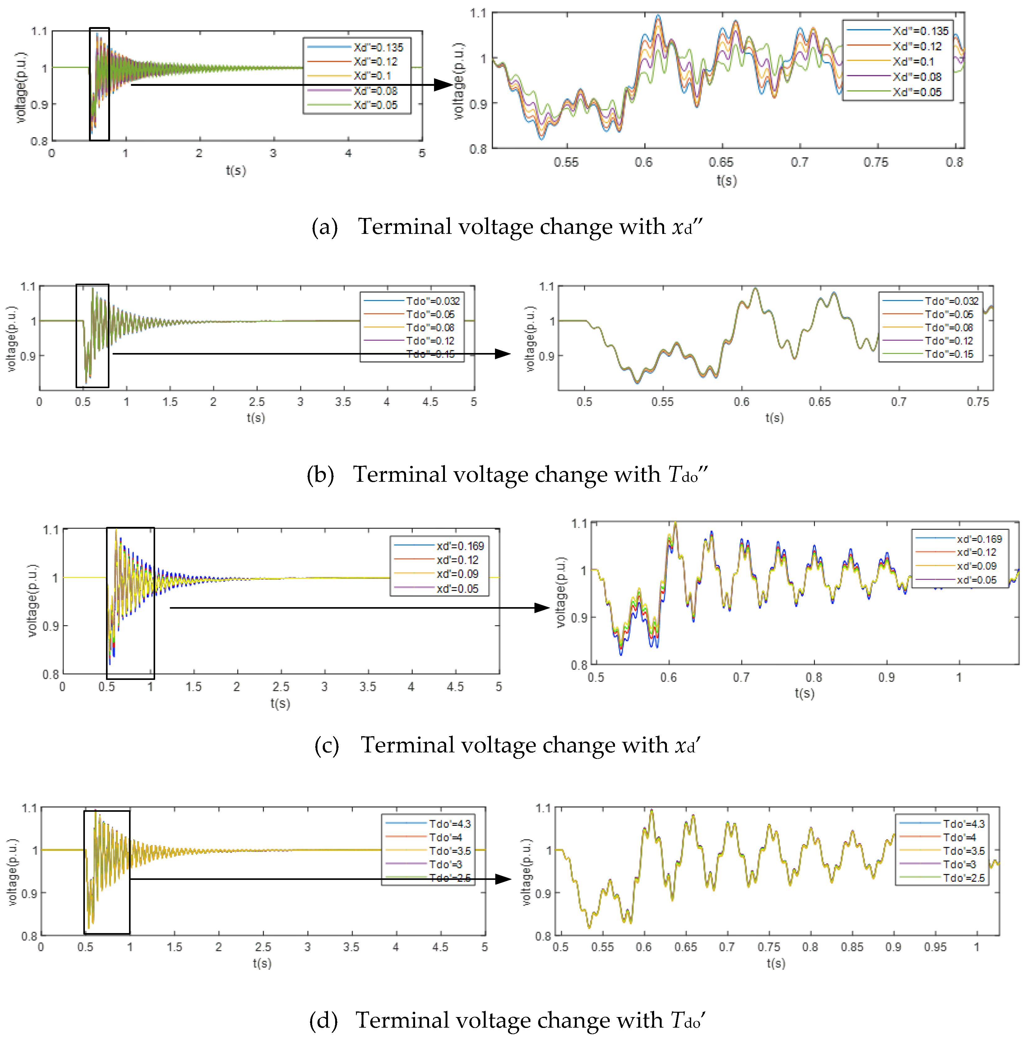
Figure 6.
virtual speed in p.u.
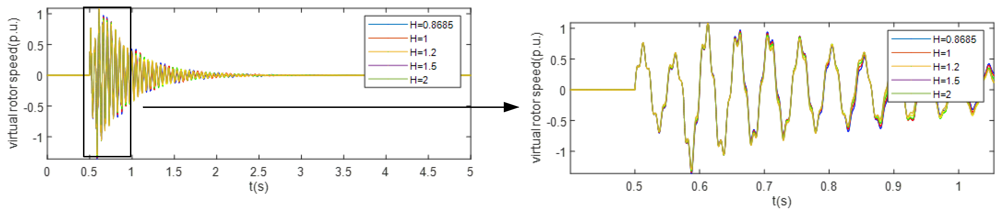
Figure 7.
Real power output in p.u;.
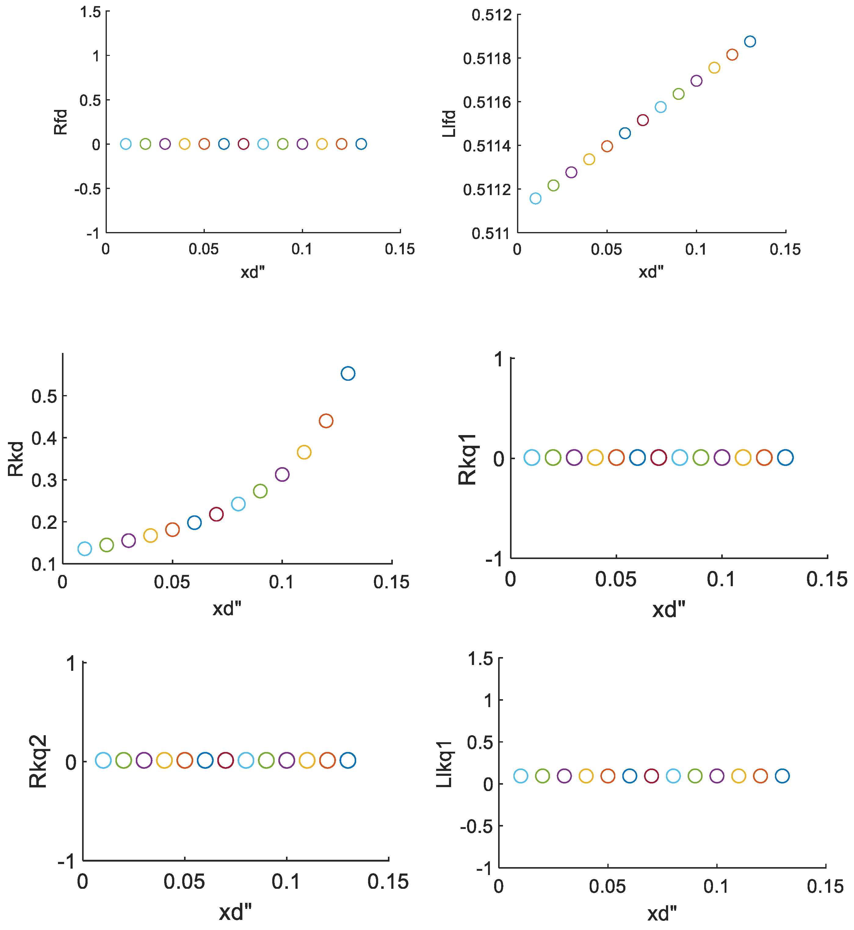
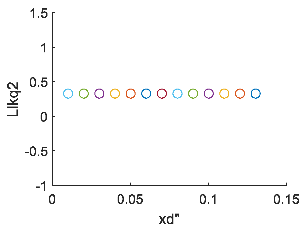
As for the parameter xd”, its change will significantly affect the value of equivalent circuit parameters, and this is why change in xd” will affect its voltage characteristics dramatically. Figure 8 shows that Llfd and Rkd are the parameters affected significantly by the variation of xd”, and these two parameters are closest to internal electromagnetic force efd, thus influencing terminal voltage. When fault occurs, the impedance at the terminal of the internal electromagnetic force will provide voltage support. This is because the smaller Llfd and Rkd, the electromagnetic force behind will act as an almost infinite bus, which is important to voltage stability when fault occurs. As for other parameters, they won’t change significantly when xd”changes, so they have little contribution in sub-transient effect
Figure 8.
(a) Change of equivalent circuit parameters with the variation of xd”.
3.2. Sub-Transient Parameter Stability Boundary
For frequency stability issues, a larger inertia will help alleviate the frequency drop at the moment of failure, but excessive inertia will also result in slow frequency recovery. Similarly, for virtual condensers, reducing the secondary transient reactance will help alleviate voltage drops during faults and voltage exceeding the upper limit after faults. However, too small a secondary transient reactance may also slow down voltage recovery and even lead to system instability after faults. In order to explore the stable boundary of the secondary transient reactance, this section will start with small signal stability analysis and investigate the stable boundary of the secondary transient reactance.
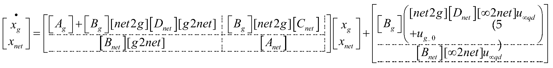
Where
are state variables for virtual condenser,
are state variables for electrical networks.
Linearize the system at the operating point to obtain its small signal model. The small signal model contains relevant terms about the sub-transient reactance, and through solving the critical sub-transient reactance parameters that cause system instability can be obtained.
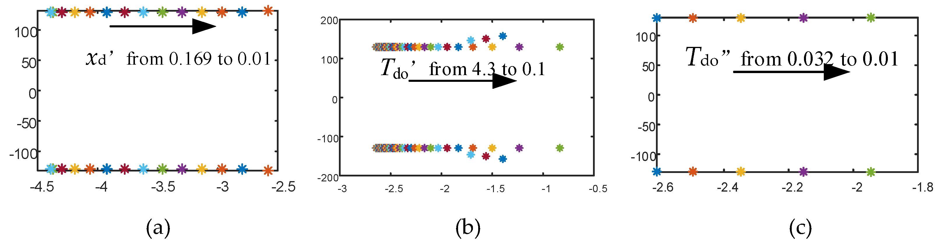
According to equation (7) and Figure 9, the eigenvalue calculation shows when xd’’ is less than 0.02, the small signal model contains eigenvalues with positive real parts, indicating system instability. This indicates that the sub-transient reactance parameters of the virtual condenser need to be kept within a reasonable range, otherwise it will lead to instability of the system and slow voltage recovery after a fault. As shown in Figure 10, change of other parameters won’t put the system into instability.
Figure 9.
(a) Change in xd” and eigenvalues (b) power output under different xd”.
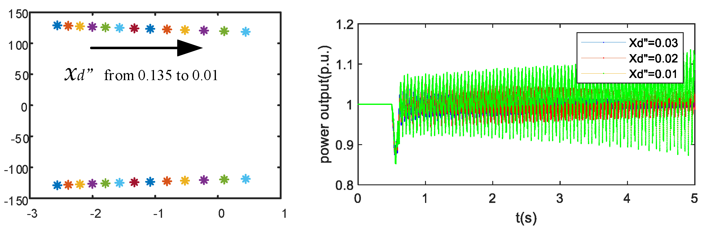
Figure 10.
(a) Change in xd’ and eigenvalues (b) Change in Tdo’ and eigenvalues (c) Change in Tdo” and eigenvalues.
Figure 10.
(a) Change in xd’ and eigenvalues (b) Change in Tdo’ and eigenvalues (c) Change in Tdo” and eigenvalues.
3.3. Comparison with Traditional VSG
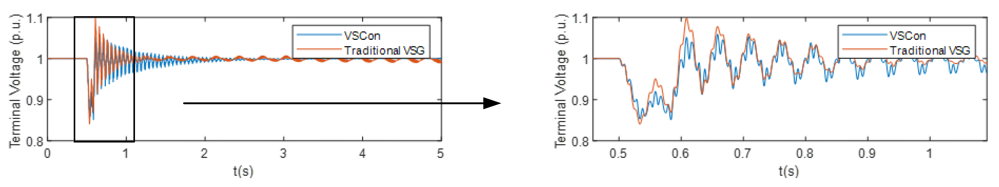
To show the advantage of the proposed VSCon, comparison is made between VSCon and traditional VSG under fault conditions as shown in Figure 11. Results show that VSCon can keep the voltage at a smaller range during the fault, while traditional VSGs cannot keep the voltage in this range. This has shown the advantage of the proposed VSCon, because it does not only have inertial characteristics as traditional VSGs have, but also have more voltage support capability.
Figure 11.
Comparison with traditional VSG.
6. Conclusions
This article introduces a control method that simulates an inverter as a synchronous condenser. By simulating the sub-transient effects and rotor equations of a synchronous motor, it can provide strong voltage support and inertia support for the power grid under short-circuit faults. The simulation results indicate that a moderate reduction in sub-transient reactance and an increase in inertia constant are more conducive to voltage support and frequency stability during short-circuit faults. At the same time, this article studied the impact of various parameters of virtual condensers on stability, and identified the parameter instability boundary, which can improve the safety and stability of condenser operation and have a better effect on the economic operation and control of the power grid.
Author Contributions
Conceptualization, Y.Y.; methodology, Y.Y; software, Y.Y.; validation, Y.Y.; formal analysis, Y.Y.; investigation, Y.Y.; resources, Y.Y.; data curation, Y.Y.; writing—original draft preparation, Y.Y.; writing—review and editing, Z. W. and Q.W.; visualization, Y.Y.; supervision, Y.Y.; project administration, Y.Y.; funding acquisition, J. X., Z. W. and Z. W. All authors have read and agreed to the published version of the manuscript.
Funding
This research was supported by the Science and Technology Project of State Grid Corporation (4000-202425081A-1-10-ZN).
Institutional Review Board Statement
Not applicable.
Informed Consent Statement
Not applicable.
Data Availability Statement
The raw data supporting the conclusions of this article will be made available by the authors on request.
Conflicts of Interest
The authors declare no conflicts of interest.
References
- State Grid Energy Research Institute. 2023 China New Energy Power Generation Analysis Report. China Electric Power Press: Beijing, China, 2023.
- Zhong, Q.C.; Weiss, G. Synchronverters: Inverters That Mimic Synchronous Generators. IEEE Trans. Ind. Electron., 2011, 58, 1259–1267. [Google Scholar] [CrossRef]
- Zhong, Q. C.; Hornik, T. Synchronverters: Grid-Friendly Inverters That Mimic Synchronous Generators. In Control of Power Inverters in Renewable Energy and Smart Grid Integration, Wiley-IEEE Press: NJ, USA, 2012; Volume 18, pp.277-296.
- Driesen, J. and Visscher. K. Virtual synchronous generators. In 2008 IEEE Power and Energy Society General Meeting - Conversion and Delivery of Electrical Energy in the 21st Century, Pittsburgh, USA, 20-24 July 2008; pp. 1–3.
- Beck, H. and Hesse R. Virtual synchronous machine. In 2007 9th International Conference on Electrical Power Quality and Utilisation, Barcelona, Spain, 9-11 October 2007; pp. 1–6.
- Zhong, Q.; Weiss, G. Static synchronous generators for distributed generation and renewable energy. In 2009 IEEE PES Power Systems Conference and Exposition, Seattle, USA, 15-18 March 2009 pp. 1–6.
- Visscher, K.; De Haan, S. W. H. Virtual synchronous machines (VSG’s) for frequency stabilisation in future grids with a significant share of decentralized generation. In CIRED Seminar 2008: SmartGrids for Distribution, Frankfurt, Germany, 23-24 June 2008; pp. 1–4.
- Mir A., S.; Senroy, N. Self-Tuning Neural Predictive Control Scheme for Ultrabattery to Emulate a Virtual Synchronous Machine in Autonomous Power Systems. IEEE Trans. Neural Networks Learning Syst., 2020, 31, 136–147. [Google Scholar] [CrossRef] [PubMed]
- Torres M., A.; Lopes L. A., C.; Morán L., A.; Espinoza J., R. Self-Tuning Virtual Synchronous Machine: A Control Strategy for Energy Storage Systems to Support Dynamic Frequency Control. IEEE Trans. Energy Convers. 2014, 29, 833–840. [Google Scholar] [CrossRef]
- Chen, J.; Liu, M.; Milano, F.; O’Donnell, T. Adaptive virtual synchronous generator considering converter and storage capacity limits. CSEE J. Power Energy Syst. To be finally published.
- Yao, F.; Zhao, J.; Li, X.; Mao, L.; Qu, K. RBF Neural Network Based Virtual Synchronous Generator Control with Improved Frequency Stability. IEEE Trans. Ind. Informat. 2020, 17, 4014–4024. [Google Scholar] [CrossRef]
- Shi, R.; Zhang, X.; Hu, C.; Xu, H.; Gu, J.; Cao, W. Self-tuning virtual synchronous generator control for improving frequency stability in autonomous photovoltaic-diesel microgrids. J. Mod. Power Syst. Clean Energy. 2018, 6, 482–494. [Google Scholar] [CrossRef]
- Wang, Y.; Zhang, Y.; Zhou, Q.; Li, Z.; Jiang, Y.; Tang, Y.; Wu, J.; Gao, C.; Tu, J.; Shen, C. Study on Application of New Generation Large Capacity Synchronous Condenser in Power Grid. Power Syst. Technol. 2017, 41, 22–28. [Google Scholar]
- Wang, Y.; Zhang, Y. Research on the application of new-generation large-capacity regulator in power grid. Grid Technology. 2017, 41, 22–28. [Google Scholar]
- Liu, Z.; Zhang, Q.; Wang, Y.; Dong, C.; Zhou, Q. Research on Reactive Compensation Strategies for Improving Stability Level of Sending-end of 750kV Grid in Northwest China. Proc. CSEE. 2015, 35, 1015–1022. [Google Scholar]
- Liu, Z.; Zhang, Q.; Wang, Y. Research on reactive power compensation measures to improve the safety and stability level of 750kV sending end power grid in Northwest New Ganqing. Chinese J. Electr. Engin. 2015, 35, 1015–1022. [Google Scholar]
- Suo, Z.; Liu, J.; Jiang, W.; Li, Z.; Yang, L. Research on synchronous condenser configuration of large-scale renewable energy DC transmission system. Electr. Power Autom. Equip. 2019, 39, 124–129. [Google Scholar]
- Suo, Z.; Liu, J.; Jiang, W. Research on the configuration of the regulator of large-scale new energy DC transmission system. Electr. Power Autom. Equip. 2019, 9. [Google Scholar]
- Sun, Y.; Cao, Z.; Wang, Q.; Wang, S. Improving Grid-Connection Reliability and Safety of Synchronous Condensers With Start-Up Process Optimization. IEEE Access. 2020, 8, 153742–153755. [Google Scholar] [CrossRef]
- Marken P., E.; LaForest, D.; D’Aquila, R.; Wallace, D.; Kronbeck, E.; Skliutas, J. Dynamic performance of the next generation synchronous condenser at VELCO. In 2009 IEEE/PES Power Systems Conference and Exposition, Seattle, USA, 15-18 March 2009; pp. 1–5.
- Jin, Y.; Yu, Z.; Li, M.; Jiang, W. Comparison of New Generation Synchronous Condenser and Power Electronic Reactive-Power Compensation Devices in Application in UHV DC/AC Grid. Power Syst. Technol. 2018, 42, 2095–2102. [Google Scholar]
- Jin, Y.; Yu, Z.; Li, M. Comparison of new generation regulator and power electronic reactive power compensation device applied in extra-high voltage AC and DC grids. Grid Technol. 2018, 42, 2095–2102. [Google Scholar]
- Nayak O. B.; Gole A. M.; D. G. Chapman; J. B. Davies. Dynamic performance of static and synchronous compensators at an HVDC inverter bus in a very weak AC system. IEEE Trans. Power Syst. 1994, 9, 1350–1358. [CrossRef]
- Fan, X.; Zhou, Y.; Ruan, L.; Zhou, K.; Wang, T.; Cao, K.; Rao, Y. Study on Transient Reactive Power Characteristics of New-Generation Large Synchronous Condenser. In 2018 China International Conference on Electricity Distribution (CICED), Tianjin, China, 17-19 September 2018; pp. 1851–1855.
- Teleke, S.; Abdulahovic, T.; Thiringer, T.; Svensson, J. Dynamic Performance Comparison of Synchronous Condenser and SVC. IEEE Trans. Power Del. 2008, 23, 1606–1612. [Google Scholar] [CrossRef]
- Marken P., E.; Depoian A., C.; Skliutas, J.; Verrier, M. Modern synchronous condenser performance considerations. In 2011 IEEE Power and Energy Society General Meeting, Detroit, USA, 24-28 July 2011; pp. 1–5.
- IEEE Guide for Synchronous Generator Modeling Practices and Parameter Verification with Applications in Power System Stability Analyses, IEEE Standard 1110-2019 (Revision of IEEE Std 1110-2002), 2020, 1-161.
- Moeini, A.; Kamwa, I.; Brunelle, P.; Sybille, G. Synchronous Machine Stability Model, an Update to IEEE Standard 1110-2002 Data Translation Technique. In 2018 IEEE Power & Energy Society General Meeting (PESGM), Portland, USA, 5-10 August 2018; pp. 1–5.
- IEEE Recommended Practice for Excitation System Models for Power System Stability Studies, IEEE Standard 421.5-2016 (Revision of IEEE Std 421.5-2005), 2016, 1-207, Aug. 2016.
- Report I., C. Computer representation of excitation systems. IEEE Trans. Power App. Syst. 1460; -87. [Google Scholar]
- Report I., C. Excitation System Models for Power System Stability Studies. IEEE Trans. Power App. Syst. 1981; PAS-100, 494–509. [Google Scholar]
- Arghir, C.; Jouini, T.; Dörfler, F. Grid-forming control for power converters based on matching of synchronous machines. Automatica, 2018, 95, 273–282. [Google Scholar] [CrossRef]
- Yazdani, A. and Iravani R. Voltage-sourced converters in power systems: modeling, control, and applications, Wiley-IEEE Press: NJ, USA, 2010. [Google Scholar]
Disclaimer/Publisher’s Note: The statements, opinions and data contained in all publications are solely those of the individual author(s) and contributor(s) and not of MDPI and/or the editor(s). MDPI and/or the editor(s) disclaim responsibility for any injury to people or property resulting from any ideas, methods, instructions or products referred to in the content. |
© 2025 by the authors. Licensee MDPI, Basel, Switzerland. This article is an open access article distributed under the terms and conditions of the Creative Commons Attribution (CC BY) license (https://creativecommons.org/licenses/by/4.0/).
Copyright: This open access article is published under a Creative Commons CC BY 4.0 license, which permit the free download, distribution, and reuse, provided that the author and preprint are cited in any reuse.


