Submitted:
31 July 2025
Posted:
01 August 2025
You are already at the latest version
Abstract
This paper presents a novel digital engineering environment for automated requirements verification in the early design of electrified aircraft. The framework establishes semantic interoperability between system models and analysis tools by employing a unified, ontology-driven data schema. At its core is a co-simulation unit that orchestrates all knowledge exchange through standardized web interfaces, enabling modular and scalable integration of system models, simulation codes, and traceability databases. Requirements are formally defined and programmatically extracted from the system model, then automatically verified against analysis results using executable representations of their constraints. All verification outcomes and supporting data are stored in a graph database, ensuring persistent traceability and enabling flexible queries across the entire workflow. Demonstrated on an electric aircraft case study, the environment enables end-to-end automation, real-time feedback, and rigorous digital continuity, addressing longstanding barriers in model integration. By advancing semantic alignment and API-based data exchange, this approach supports the development and certification of sustainable aviation systems.
Keywords:
digital thread
; model-based systems engineering
; interoperability
; requirements verification
1. Introduction
The aviation industry is under increasing scrutiny due to its environmental impact, particularly its contribution to global greenhouse gas emissions. Aviation currently accounts for approximately 2.5% of global CO2 emissions [1], and if current trends persist, its share could increase to 11% by 2050 in the absence of technological advances [2]. The rapid growth of global air travel continues to outpace emissions reduction efforts; hence there is an urgent need for systemic innovation in aircraft design and operations [1,3,4,5,6]. To meet ambitious international climate goals, such as those set by the U.S. Aviation Climate Action Plan [7], the EU ACARE Flightpath 2050 [8], and the UK’s Jet Zero Technology Strategy [9], the industry must achieve net-zero CO2 emissions by 2050. These strategic frameworks are shaping research, innovation, and investment across public and private sectors, driving a shift toward sustainable aviation technologies, including electric and hybrid-electric propulsion systems, hydrogen fuel solutions, and Sustainable Aviation Fuels (SAFs) [7,9,10,11,12,13,14,15].
According to leading aviation decarbonization frameworks such as Waypoint 2050 [16] and Destination 2050 [8], options for reducing CO2 emissions include (1) technology improvements, such as disruptive aircraft configurations and zero-emission propulsion (hydrogen and electric aircraft), (2) sustainable aviation fuels, which offer reduced lifecycle emissions, (3) operational improvements, including efficient routing and air traffic management, (4) market-based measures, such as offsets and carbon removals, and (5) policy support and infrastructure investment, which are essential for enabling technological transitions. These pathways must be pursued in parallel. Moreover, aviation’s operational and geographical diversity, ranging from short regional flights to long-haul intercontinental operations, means that no single solution will suffice [16]. Instead, achieving net-zero aviation requires a flexible, adaptive design framework that can accommodate and integrate a variety of technologies and strategies tailored to specific aircraft types, missions, and regional contexts.
Integrating these emerging sustainable aviation technologies into aircraft is a complex challenge, as it involves new fuel types, novel powertrain architectures, and stringent safety and certification requirements [17]. The increasing complexity and interconnectedness of novel aerospace systems and system-of-systems require an overarching framework to organize modeling, simulation, and analysis artifacts, moving beyond isolated tool use and manual data transfer [18,19]. Systems Engineering (SE) approaches, especially Model-Based Systems Engineering (MBSE), have emerged as a paradigm for formalizing system artifacts and development throughout the entire life cycle using digital models, supporting activities such as structural analysis, process modeling, and data flow diagrams [20]. In practice, MBSE workflows rely on a diverse set of authoring, simulation, and design tools, such as SysML authoring tools (e.g., Cameo Systems Modeler, MagicDraw), Modelica, and others, each employing distinct modeling specifications, metamodels, and semantics. While these multi-tool MBSE tool-chains enable interdisciplinary and multi-domain design, they also introduce significant interoperability challenges. Heterogeneous data structures and formats can result in inconsistent model interpretation, semantic information loss, and difficulties in capturing and exchanging system composition, interfaces, and parameters across tools and stakeholders.
Poor interoperability complicates collaborative engineering, increases system development costs, and introduces risks of inconsistency as requirements evolve and system architectures change across domains and tools. These risks are amplified in the sustainable aviation context, where increased interdependencies between system elements arise as novel configurations, such as electric and hydrogen-powered aircraft, are designed. Certification and regulatory uncertainty further complicate the integration of emerging technologies, while lifecycle trade-offs on sustainability metrics and the challenge of infrastructure readiness for novel energy systems add additional layers of complexity. In the fast-evolving landscape of sustainable aircraft design, the absence of robust, traceable change management mechanisms can lead to misaligned requirements, fragmented system understanding, and increased certification risk. An interoperable digital engineering environment enables stakeholders to rigorously model and analyze complex system interdependencies, respond effectively to changing certification and regulatory requirements, assess infrastructure readiness, and balance sustainability metrics with traditional performance objectives. Crucially, such an environment also provides the foundation for developing and validating new policies and certification pathways for novel aerospace systems. Addressing these challenges is critical to accelerating the adoption of sustainable technologies and achieving the ambitious climate targets set by the global aviation sector.
To address these critical gaps, namely, poor interoperability, fragmented system understanding, and limited traceability in complex, multi-tool environments, a modular digital engineering environment is proposed for sustainable aircraft design. In this approach, a SysML v2-based MBSE system model, a Python-based MDO tool, and a Neo4j graph database are integrated, with all data exchange coordinated by a central co-simulation unit using standardized RESTful APIs. By channeling all tool interactions through the co-simulation unit, clean interfaces, robust traceability, and consistent semantic interpretation are ensured across modeling and analysis domains. Through this architecture, a range of downstream engineering tasks, including automated requirements verification, traceable change management, and architecture tradeoff studies, can be enabled within a unified digital environment. In this paper, the use of this environment for automated verification of system-level requirements in the early design of electrified aircraft architectures is detailed, demonstrating its potential to help overcome the integration and certification challenges in sustainable aviation.
The remainder of this paper is organized as follows. Section II provides background and relevant work, including an overview of foundational concepts in MBSE model interoperability, recent advances in integrating and interconnecting engineering models, and a summary of efforts to apply these approaches within the context of sustainable aviation. Section III introduces the proposed modular digital engineering framework, outlining its architecture and main components. Section IV presents a case study focused on the early-stage design of an electrified aircraft to demonstrate the framework’s application. Section V discusses the results, while Section VI concludes the paper and outlines directions for future research.
2. Background and Related Work
This section first outlines the foundational principles of MBSE-enabled model integration and interoperability, highlighting key concepts such as the digital thread. Next, it reviews the current state of the art in MBSE–engineering model integration, drawing on recent academic and open-source frameworks, as well as selected commercial solutions, to characterize the range of approaches and their limitations. Finally, the discussion transitions to recent efforts and specific challenges associated with applying MBSE-driven integration methods in the context of sustainable aviation, thereby motivating the focus and contributions of this work.
2.1. Foundations in MBSE-Enabled Engineering Model Integration and Interoperability
MBSE fundamentally shifts systems engineering practice from traditional document-centric approaches toward digital, model-centric methodologies [21]. By leveraging formally defined system models to capture requirements, architectures, behaviors, and interdependencies, MBSE facilitates enhanced traceability, collaboration, and automation, mitigating common pitfalls such as fragmented communication, manual data handling errors, and inefficient reuse of knowledge [22,23]. Central to fully realizing MBSE’s benefits is the broader paradigm of Digital Engineering (DE), which encompasses digitally capturing, integrating, and managing engineering artifacts throughout the system lifecycle [24]. DE extends MBSE by enabling continuous data integration, simulation-driven design, and automated verification, all crucial for managing increasingly complex and interconnected systems [25,26].
Effective DE and MBSE integration relies heavily on interoperability, the ability of systems to exchange and use information effectively [23,27,28]. Interoperability operates at multiple levels: Syntactic interoperability ensures that data formats and structures are compatible for exchange, typically using standardized formats such as XML, JSON, or CSV. While syntactic interoperability facilitates data sharing, it does not guarantee a common interpretation or meaning [29]. Semantic interoperability provides a shared understanding of exchanged information across different tools and models, achieved through common vocabularies, ontologies, or standardized specifications such as SysML and ReqIF [29]. Semantic interoperability ensures consistent interpretation of data, enabling automated reasoning [19,29].
The literature shows that model integration enhances MBSE by linking system views and facilitating information sharing across engineering domains and tools. Interoperability, the ability of systems to exchange and use information effectively [23,27,28], is essential for realizing these benefits, enabling reduced development time, lower costs, and improved accessibility of information [30]. The concept of the digital thread captures this progression from isolated models to a series of models working together in an integrated environment across the system life cycle [31]. Where multiple models contribute parameters, constraints, or other data to larger design and analysis tasks, the digital thread establishes explicit connections that support more automated and semi-automated analyses, reducing errors from manual data handling [32]. Integrating SysML-based (descriptive) and simulation-based (analytical) models thus underpins the digital thread, supports earlier and more frequent analysis, and leads to more informed decision-making.
2.2. Current Practice on Interoperating Engineering Models with MBSE System Models
The AGILE [33] and AGILE 4.0 [34] projects have progressively advanced model-driven integration of MBSE and MDO for collaborative aircraft design. Early AGILE work (Fioriti et al., 2020) focused on distributed, expert-in-the-loop MDO using standardized process integration and central data schemas, without direct MBSE-driven architecting [35]. Building on this, AGILE 4.0 introduced a comprehensive framework for linking stakeholder needs, requirements, and system architectures to multidisciplinary analysis and optimization via automated, traceable workflows [36,37]. Central to this methodology is the use of architecture design space graphs, common data schemas (CPACS), and automated mapping tools (e.g., MultiLinQ) to enable data flow between MBSE models and disciplinary analysis tools. Subsequent application papers demonstrate the effectiveness of this framework for various use cases, including value-driven, certification-driven, and function-based architecture optimization across product and enabling systems [38,39,40,41,42]. These studies collectively highlight the benefits of the AGILE 4.0 approach in enhancing traceability, collaboration, and automated design space exploration. Despite these advances, challenges remain in fully automating MBSE–MDO mappings, generalizing the approach beyond domain-specific schemas and toolchains, furthering model validation and verification, and scaling the methodology for broad industrial adoption.
Beyond AGILE, recent efforts to integrate MBSE and engineering analyses have employed various approaches, such as using SysML activity diagrams to orchestrate simulation and optimization workflows with external tools [43,44]. These methods facilitate requirements verification and workflow traceability but remain constrained by limited automation and scalability. Manual mapping between SysML requirements diagrams and MDO environments, as seen in Aïello et al. (2022) [45], or static SysML–CAD model integration using standardized formats [46], enhances traceability but lacks dynamic analysis and co-simulation capabilities.
Automation is further advanced in the frameworks proposed by Fouda et al. (2024) [47] and Gazaix et al. (2024) [48], who formalize the extraction of multidisciplinary optimization problems directly from SysML-based product and process models. In the study by Fouda et al. [47], a custom Python middleware interacts with SysML authoring tools to automatically extract optimization variables, constraints, and objectives, which are then executed within the GEMSEO MDO framework. Gazaix et al. [48] employ SysML activity diagrams to define MDO workflows, exporting process specifications as YAML files and instantiating high-fidelity MDO runs in GEMSEO via tailored middleware. Both approaches ensure traceability from requirements to analysis results, but full automation is yet to be achieved; the integration steps often require manual intervention, and a unified, domain-independent data schema for interoperability is not established.
Digital thread and traceability concepts are pushed further by Dunbar et al. (2023) [31] and Wu et al. (2025) [19]. Dunbar et al. [31] implement an Authoritative Source of Truth (AST) by importing SysML artifacts into a triplestore database, enabling standardized data exchange through REST API calls. This facilitates traceable, standards-based integration between MBSE and engineering analysis models, with analysis parameters and results exchanged as JSON documents. Wu et al. [19] advance this further with a cognitive digital thread tool-chain, harmonizing heterogeneous models using a unified metamodel and OSLC-based web services, while managing version history and model evolution in a Neo4j knowledge graph for enhanced conflict detection and traceability. Despite these technical advances, both frameworks still rely on custom adapters, middleware, or file-based exchanges for tool interoperability, which constrains real-time synchronization and scalability. As a result, their applicability to broad industrial contexts and robust, dynamic digital engineering environments remains an open area for further research and development.
Emerging frameworks demonstrate progress in automation and real-time integration, but important challenges remain. Castellano (2025) [49] introduces a SysML v2 and Python-based environment that automates requirements verification and connects simulation results back to the system model using custom wrappers, yet integration with multidisciplinary analysis tools and co-simulation is not fully realized. Grunenwald et al. (2025) [50] achieve real-time, bidirectional data exchange between SysML v2 and BPMN process models via custom middleware and mapping tools, enabling dynamic assessment of architecture–process impacts, but their approach does not link to engineering analyses or support automated, cross-domain requirements verification.
Other recent efforts focus on improving model transformation and interoperability. Chu et al. (2022) [51] use a model-to-text approach to convert SysML architectures into simulation models for design verification, while Lucas et al. (2023) [52] enable programmatic access to SysML v2 models through the PySysML2 toolkit. However, both approaches fall short of providing automated feedback from analyses to requirements or system models. Standards-based co-simulation is advanced by Hällqvist et al. (2022) [53] using System Structure and Parameterization (SSP) and Functional Mock-up Interface (FMI) for real-time, tool-agnostic parameter exchange, and by Madni (2021) [25] through orchestration of virtual and physical testing, but both approaches encounter limitations in requirements traceability, scalability, and real-time model feedback.
In addition to the above, OpenMBEE has emerged as a significant open-source platform facilitating integration between SysML models and diverse analysis tools through its View Editor and API-based architecture [54]. OpenMBEE enables synchronized, standards-based data exchange, supports the development of custom tool connectors, and has been used to automate requirements traceability and design feedback in complex, multi-tool engineering environments. Several commercial platforms also support MBSE–analysis integration, including ANSYS ModelCenter MBSE [55], Dassault Systèmes 3DEXPERIENCE (CATIA Magic, Cameo) [56], Siemens Teamcenter/NX/Simcenter [57], and Syndeia (Intercax) [58], which offers vendor-neutral digital thread connectivity across SysML, simulation, and Product Lifecycle Management (PLM) tools. While these solutions enable advanced integration and traceability, they are often costly, cater to niche markets with restricted distribution, and rely on proprietary, tool-specific formats [52]. A more fundamental challenge remains the absence of open, standardized formats for documenting and sharing systems models, limiting broader interoperability and collaboration.
The reviewed literature, as summarized in Table 1, highlights a range of integration strategies spanning executable SysML workflows, custom middleware, model transformation, and co-simulation. Rows for Bruggeman et al. (2023) [59] and Zhang et al. (2023) [60] are included in both the main comparative table and the focused discussion of integration frameworks for sustainable aviation (see Section II.C), reflecting their relevance to this emerging domain. While each approach advances interoperability and traceability to varying degrees, most solutions remain limited by manual data exchanges, the absence of unified data schemas, or the lack of automated feedback from analysis results to the system model. This aligns with the findings of Schumacher et al. (2025) [61], who conducted a systematic review of SysML-based process chains and observed that data transformation is typically managed through custom APIs, XML files, or semantic mapping, with SysML models serving as the primary source for downstream simulation or analysis. Despite supporting architecture definition and early verification, such process chains often suffer from incomplete integration of requirements models, infrequent or manual feedback from simulations, and a lack of closed-loop, standards-based data exchange for continuous verification.
2.3. Existing MBSE Efforts for Sustainable Aviation
Several recent studies have explored MBSE applications in sustainable aviation. Kuelper et al. (2025) focused on the early architecture development of hydrogen fuel systems, using SysML models generated via the Systems Architecting Assistant (SArA) and integrated with model-based safety assessments [17]. The methodology allowed for automated generation and filtering of architecture candidates based on safety criteria. Positive outcomes included improved compliance with safety regulations and early elimination of nonviable concepts. However, the work lacked integration with MDO tools and did not address semantic alignment or co-simulation, limiting its capability for performance-based trade-off analysis. Tan et al. (2024) developed a detailed SysML model of a hydrogen combustion turbofan engine to explore design impacts of switching fuels [62]. The model effectively traced system-level changes driven by hydrogen’s unique properties, including cooling and storage needs. While the study highlighted the value of functional decomposition and requirement traceability, it did not incorporate performance simulation or MDO integration. The absence of a common data schema or simulation link restricted the model’s utility in iterative system evaluation. Hu et al. (2024) introduced a structured Mission–Operational–Functional–Logical–Physical (MOFLP) framework to support electrified aircraft propulsion design [63]. The authors emphasized mission-driven architecture exploration and verification using SysML-based models. Although the methodology enabled systematic design evaluation, it did not include dynamic co-simulation or semantic interoperability with quantitative analysis tools, highlighting the need for improved integration frameworks. Bruggeman and La Rocca (2023) present the Design and Engineering Engine (DEE), a holistic model-based framework that integrates MBSE, MDO, and Knowledge-Based Engineering (KBE) to support digitalized aircraft conceptual design [59]. While the DEE provides a conceptual blueprint for connecting requirements, system architectures, and multidisciplinary analysis via a central data schema, its implementation remains largely at the architectural level. Notably, the technical realization of standards-based integration between MBSE (e.g., SysML v2) and MDO environments, along with fully automated, bidirectional requirements verification and traceability, is not demonstrated. Zhang et al. (2023) demonstrated the integration of MBSE and MDO using SysML v2 in the conceptual design of a hydrogen-powered aircraft [60]. They used SysML v2’s textual notation and a custom Python parser (via PyParsing) to extract model elements, such as part definitions, requirements, and parameters, and convert them into CSV inputs for the custom MDO tool, ADAPT [64]. Analysis results were reinserted into the model, enabling bidirectional updates and requirement verification. While effective, the integration is limited to syntactic interoperability via a tool-specific parser and file-based data exchange, without addressing semantic alignment between models and analysis tools. The absence of a shared data schema or ontological framework restricts reusability across different MDO environments. The process also relies on batch-style updates and manual regeneration of SysML models, lacking real-time feedback or cosimulation capabilities. These limitations raise concerns about scalability, maintainability, and generalizability of the approach for broader digital engineering ecosystems.
In summary, although significant progress has been made in integrating MBSE with engineering analysis and optimization tools, most current frameworks are constrained by limited automation, the absence of open, standardized data schemas, and incomplete support for real-time, bidirectional feedback between system models and analysis environments. Manual data exchange, proprietary toolchains, and a lack of closed-loop verification continue to hinder digital continuity and scalability, especially in emerging domains such as sustainable aviation. To address these gaps, this paper proposes a modular digital engineering environment that tightly couples MBSE, MDO, and graph-based data management within a co-simulation-enabled framework. The approach specifically targets automated requirements verification and traceable system-level analysis for sustainable aviation design, establishing digital continuity and interoperability across disciplines.
3. Proposed Framework
To address the limitations identified in the literature, a digital engineering environment is proposed which is built on a modular, layered architecture that emphasizes scalability, interoperability, and traceability throughout the design process. The core components of this architecture include a system model developed in SysML v2, engineering models, a co-simulation unit realized as a REST API (using FastAPI), and a Neo4j graph database for persistent knowledge storage and requirements traceability (see Figure 1). Each component operates as an independent module, with well-defined responsibilities and strictly controlled communication channels to reduce coupling and improve maintainability. Central to the framework is the co-simulation unit, which serves as the sole point of contact between components: only the co-simulation unit is permitted to communicate directly with the system model, engineering analysis tools, and the Neo4j database. This design enforces clean, standardized interfaces, minimizes the risk of inconsistent data exchange, and greatly facilitates future extensibility of the environment. The data exchange between all modules is governed by a common ontological metamodel, rooted in SysML v2 semantics and extended as needed for engineering analyses. Each engineering tool or model integrates with the environment through a schema mapping interface, translating its native data structures to and from the ontological metamodel. This approach ensures semantic alignment, robust traceability, and persistent, queryable storage of all system knowledge within the Neo4j graph database.
While the architecture is designed to support the connection of multiple, heterogeneous engineering models via the co-simulation unit, this study demonstrates the framework using a single engineering tool, an MDO model implemented in Python. This focused use case allows for a clear illustration of the data flows, automated requirements verification, and integration mechanisms, while preserving the generality and extensibility of the proposed digital engineering environment. The components of this environment are explained in detail in the following subsections.
3.1. Co-Simulation Unit
The core of the proposed digital engineering framework is a co-simulation unit that acts as the central orchestrator for tool interoperability and automated requirements verification. The co-simulation unit is implemented as a RESTful API using FastAPI, due to its simplicity, extensibility, and compatibility with web-based and cloud-native environments. The co-simulation unit exposes endpoints that allow external engineering tools such as MBSE system modeling environments and MDO solvers to interact through standardized HTTP protocols. Within the framework, the co-simulation unit coordinates the following tasks: (1) retrieves system requirements directly from the SysML v2 system model, (2) initiates and manages simulation or optimization runs via the MDO tool, (3) processes and verifies simulation results against formalized system requirements using automated parsing and evaluation routines, (4) updates system verification status and traceability information in a Neo4j graph database for downstream analytics and compliance reporting. This architecture is designed to be modular and extensible, supporting the integration of additional analysis, verification, or data management tools with minimal disruption to the core workflow.
3.2. MDO Tool
The MDO tool is a core analytical component of the proposed digital engineering environment. It was implemented using OpenMDAO [65], combining components from the OpenConcept library [66] with custom extensions. The tool provides a low-fidelity, physics-based analysis capability that is appropriate for early conceptual design of electrified aircraft architectures.
3.2.1. Propulsion Models
The propulsion model includes simple, conceptual-level components designed for low-fidelity, computationally efficient analysis appropriate for early-stage design and trade studies of electric aircraft. Key elements of the propulsion model include:
- SimpleMotor: Represents an electric motor with a constant assumed efficiency. The motor outputs shaft power proportional to its rated power and throttle setting while simultaneously determining the required electrical power from the connected upstream source (i.e., battery).
- SOCBattery: Models an electrical power source with constant specific power and specific energy, providing energy to meet motor demands while tracking state-of-charge depletion.
- SimplePropeller: Converts shaft power to thrust using an empirical efficiency map as a function of advance ratio and power coefficient [67].
- Splitter: Handles combining or dividing power between sources or loads.
These components are developed as OpenMDAO ExplicitComponent objects, and can be connected to model various propulsion architectures. Mechanical components are modeled as pushing shaft power based on throttle, while electrical components pull electrical power from sources such as generators or batteries [66]. A Newton solver adjusts engine throttle to ensure sufficient shaft power is supplied to meet motor electrical demand at each flight condition. Battery state-of-charge depletes automatically according to demand without special treatment.
3.2.2. Thermal Management Models
A modular thermal management framework [68] to model the heat rejection process in an electric propulsion system using OpenMDAO is employed. The system consists of a liquid-cooled heat sink, an air-cooled heat exchanger, a coolant reservoir, and a duct-driven airflow module. The electric motor generates heat, which is absorbed by a liquid-cooled heat sink. The heated coolant flows into an air-cooled heat exchanger, where heat is rejected to ram air supplied by an incompressible duct model. The cooled fluid then enters a reservoir, which buffers temperature and returns the coolant to the motor.
The duct model calculates air mass flow rate and drag based on vehicle speed, air density, and the pressure drop across the heat exchanger. This bidirectional coupling allows the system to account for interactions between thermal resistance and aerodynamic performance. All subsystems are linked via promoted variables and use shared inputs such as coolant mass flow rate, channel geometry, and freestream conditions. This setup enables rapid analysis of thermal and aerodynamic performance under varying mission conditions.
3.2.3. Mission Analysis
In this study, takeoff and mission analyses were conducted, which offers analytically-differentiated, reusable modules suitable for gradient-based optimization. The takeoff analysis module computes Balanced Field Length (BFL) by numerically integrating the equations of motion across various segments such as the initial takeoff roll, One Engine Inoperative (OEI) roll, rejected takeoff braking, transition, and OEI climb, to determine the critical takeoff decision speed () that equalizes accelerate-go and accelerate-stop distances. The takeoff module takes as inputs the Maximum Takeoff Weight (MTOW), propulsion system rated power, thrust control settings, aerodynamic characteristics (e.g., lift and drag coefficients), aircraft geometry, and runway conditions, and produces outputs including BFL, , segment distances, battery energy consumed during takeoff, and propulsion system states. The mission analysis module handles steady-state climb, cruise, and descent by setting control inputs and satisfying thrust equilibrium at each flight condition using a Newton solver. It integrates quantities such as battery usage over time using Simpson’s rule. Inputs to the mission module include the design mission range, phase speeds and altitudes, propulsion architecture, aerodynamic data, payload weight, and initial battery states, while outputs include battery State Of Charge (SOC) profiles, phase times and distances, propulsion loads, and residuals for thrust-drag and weight balances.
3.2.4. Aerodynamics Models
The aerodynamics model used in this study is adopted directly from the OpenConcept [66] without modification. It represents the aircraft’s aerodynamic characteristics using a simple drag polar formulation, suitable for conceptual-level analysis. The model provides estimates of lift and drag forces based on dynamic pressure, reference area, and drag polar parameters, supplying required aerodynamic data for integration with the propulsion, thermal, and mission dynamics models. This approach offers computational efficiency while maintaining sufficient fidelity for early-stage multidisciplinary design optimization.
The framework employs the standard atmospheric model provided by OpenConcept [66] to compute altitude-dependent properties such as air density, temperature, and pressure based on the International Standard Atmosphere (ISA). These properties are supplied to the aerodynamic, propulsion, and mission dynamics models throughout the mission profile. In addition, the framework uses OpenConcept’s utility modules to support the setup and execution of the multidisciplinary design optimization problem. These utilities include tools for variable promotion, data interpolation, flight condition conversions, and configuration of mission phases and solver settings.
3.3. System Model
SysML v2 was chosen for this work because it overcomes many of the limitations that come with SysML v1 and offers significant advances in openness, interoperability, and semantic precision. First, while SysML v1 lacks a standard API, making it difficult for engineering tools to navigate, query, or update models without custom programming interfaces, SysML v2 introduces a standardized API, allowing tools to interact with models using modern programming languages and supporting interoperability across the toolchain [26,69]. Second, SysML v1 is constrained by its foundation as a UML extension, limiting expressiveness and semantic clarity. SysML v2 adopts a new metamodel based on core declarative semantics and formal logic, enhancing the expressiveness, precision, and extensibility needed for semantic alignment with engineering data [69,70]. Third, SysML v1’s dependence on the XMI format has proven cumbersome, particularly for exchanging large or distributed models. SysML v2 instead provides a modern textual notation that facilitates natural file exchange, as well as a standard API for dynamic, repository-based or file-based exchange using a common data representation [69,70].
The central objective here is to construct a system model that can formally represent an MDO architecture using SysML v2 [71]. In traditional workflows, MDO tools are developed independently of systems engineering models, limiting their ability to interoperate with architectural decisions, requirements, and traceability structures. This work addresses that gap by using the system model not merely as a static representation of system elements, but as an active, semantically structured layer that encapsulates the MDO workflow, its components, and the relationships among them. To achieve this, the development process is organized into two tightly interwoven perspectives: modeling effort and model usage, both centered around MDO representation.
The modeling effort begins with the development of a structured ontological metamodel derived from an MDO-specific ontology. This ontology captures key concepts such as disciplinary analyses, input-output relationships, and computational dependencies. It serves as the foundation for defining SysML constructs such as part definitions, value properties, logical components, and interfaces. These constructs are used to build a domain-specific system model that reflects both the physical aircraft architecture and the underlying MDO workflow. The system model is developed using the SysML v2 Pilot Implementation [72] in a Jupyter-based environment, enabling automation and integration with external tools. The Object-Oriented Systems Engineering Methodology (OOSEM) is adopted to guide the modeling process, due to its structured life-cycle processes, modular object-oriented approach, and alignment with international systems engineering standards [73]. The model includes physical subsystems (e.g., electric motor, battery, heat exchanger), logical analyses (e.g., aerodynamics, mission simulation), and requirements (e.g., TOFL, SOC) allocated to relevant components.
In practice, the primary function of the system model is to serve as a semantically precise, descriptive interface for automated, standards-based communication with external engineering tools. Instead of directly executing analyses within SysML, the model defines the structure, interfaces, and requirements of the system, and exposes this information for machine-to-machine interaction. Through a schema mapping interface and the co-simulation unit, the SysML v2-based system model is programmatically synchronized with the Python-based MDO environment. This enables the automated transfer of system architecture, requirements, and design data to the analysis tool, while supporting the return of verification results and performance metrics to the system model. In this way, the system model is not only an authoritative repository for system knowledge, but also a dynamic participant in closed-loop, traceable, and automated multidisciplinary analysis and requirements verification.
3.4. Neo4j Graph Database
To ensure long-term traceability and persistent storage of requirement verification outcomes, a Neo4j graph database was integrated into the architecture. Neo4j was chosen based on its suitability for modeling complex relationships among entities such as system elements, requirements, and verification statuses. Interactions with the database were centralized through the co-simulation unit, which manages the logging of outputs and the status of each requirement. This design supports future queries about design evolution, compliance trends, and decision rationales, aligning well with digital thread principles.
4. Case Study: Electrified Aircraft
The Pipistrel Velis Electro [74] was chosen as the testbed for this framework due to its status as the first and only EASA-certified fully electric aircraft, making it a practical and credible benchmark for sustainable aviation studies. Its relatively simple architecture and publicly available specifications provide an ideal foundation for modeling, verification, and early design exploration. The key technical specifications used to configure the model are summarized in Table 2.
In the following subsections, the implementation of the proposed framework given in Section III as applied to the Velis Electro is described. First, the development of the MDO environment tailored to the aircraft’s architecture and mission profile is presented. Next, the construction of a semantically aligned system model in SysML v2 is outlined, including the ontology and schema mapping process. Finally, the co-simulation unit is introduced, through which automated requirements verification is enabled by integrating the system model with the MDO framework and supporting digital thread traceability.
4.1. MDO Implementation
The baseline OpenConcept framework [66] was adapted to capture the key characteristics of the Pipistrel Velis Electro. The standard atmosphere and weight interpolation models are adopted without change. The vehicle’s aerodynamic representation uses the default polar model, while the propulsion and thermal subsystems are assembled from OpenConcept modules and parameterized to match published data given in Table 2. The Pipistrel Velis Electro’s propulsion architecture consists of a fully electric powertrain supported by a dual battery configuration and an active thermal management system. Electrical energy is supplied by two parallel battery packs, each modeled with specific energy and efficiency characteristics. A power splitting unit distributes the load between the two batteries and feeds an electric motor, which delivers shaft power to a fixed three-blade propeller, as shown in Figure 2. During operation, the motor generates waste heat, which is dissipated through a closed-loop liquid cooling system. This system includes a motor-mounted heat sink, a coolant reservoir, a counter-flow heat exchanger, and a duct that simulates ambient airflow during flight. The cooling loop dynamically regulates temperature by circulating coolant through these components, with heat transfer driven by mission-specific flow and thermal conditions.
This aircraft model is used for the representative mission segmented into takeoff, climb, cruise, and descent phases as shown in Figure 3. The mission-level model integrates propulsion, aerodynamics, and thermal dynamics across all phases. The following are the primary outputs of interest: final State of Charge (SOC) of both batteries, and Takeoff Field Length (TOFL) (evaluated as range covered until 50 ft obstacle height after rotation). The model is configured with a Newton solver and a ScipyOptimizeDriver to support constrained optimization. The objective is to maximize mission range, while constraints ensure battery depletion does not fall below zero at the mission’s end.
The mathematical representation is given in Equation 1. R denotes the total mission range in nautical miles, which serves as the optimization objective. represents the takeoff field length, measured as the horizontal distance required to clear a 50-foot obstacle. and refer to the final state of charge of Battery 1 and Battery 2, respectively. The vector contains system state variables such as altitude, battery SOC, and temperature, while represents the control inputs for the mission, including throttle settings, airspeed, and vertical speed for each segment.
After this MDO workflow is established, a SysML v2 system model was developed, as described in the following subsection.
4.2. System Model Development
In this study, the system model was developed from the ground up, rather than adapting an existing SysML v2 architecture. This approach enabled the creation of a flexible and generalizable schema mapping interface tailored specifically to the needs of the case study. The process began with a comprehensive analysis of the OpenMDAO-based MDO framework, focusing on its components, variable structures, data flows, and dependency relationships. Insights from this analysis informed the formulation of an ontological metamodel using SysML v2 constructs, designed to accurately capture the semantics of the engineering analysis domain. Then, the ontological metamodel guided the development of the SysML v2 model.
4.2.1. Ontological Metamodel and Schema Mapping Interface
A core challenge in achieving interoperability between the system model and external analysis tools is the semantic alignment of their underlying data structures and metadata. In this work, the integration process began with a detailed analysis of the OpenMDAO-based MDO framework to identify key schema elements including components, variables, inputs, outputs, and interconnections. Based on this analysis, an ontological metamodel was constructed, using SysML v2 semantics to capture essential relationships and computational dependencies present in the engineering analysis. Table 3 summarizes this mapping. Notably, the SysML v2 model does not replicate the detailed computational logic already present in the MDO framework; instead, it abstracts and organizes the interfaces, parameters, and relationships necessary for effective data and knowledge exchange. The resulting metamodel serves as the common data schema for interoperability within the digital engineering environment. The schema mapping interface defines explicit correspondences between elements of the OpenMDAO schema and constructs in the SysML v2 ontological metamodel, ensuring consistent translation of information between the analysis tool and the system model.
4.2.2. Creating the System Model in SysML v2
With the ontological metamodel established, the system model was manually constructed in SysML v2 using the Pilot Implementation [72] in a Jupyter-based environment. This iterative process allowed for continuous validation and ensured that the SysML v2 model mirrored the MDO workflow’s structure and logic while enabling automated data exchange and future scalability. If a pre-existing SysML v2 model were available, integration would have focused directly on schema mapping to the ontological metamodel.
The translation process mapped each OpenMDAO component such as motors, propellers, batteries, and power splitters, to SysML v2 part definitions, with declared inputs and outputs corresponding to ports typed by appropriate interfaces (e.g., power, mass flow, thermal energy). Interconnections in OpenMDAO were represented as connect statements in SysML v2, preserving the directionality and flow of energy, mass, and information. All OpenMDAO elements were modeled as parts in SysML v2 without explicit categorization into logical, physical, or functional views, focusing instead on structural and data flow relationships. Nested subsystems in OpenMDAO were captured as hierarchical part structures within SysML v2, such as propulsion or thermal management assemblies.
To visualize the developed model, PlantUML [76] was used to generate Block Definition Diagrams (BDD) and Internal Block Diagrams (IBD) directly from the SysML v2 code. BDDs illustrate the hierarchical decomposition of the system (e.g., propulsion system hierarchy in Figure 4), while IBDs show ports, interfaces, and internal connections (e.g., propulsion system components and their interconnections in Figure 5), with all labels and relationships derived from the system model’s defined semantics.
4.3. Co-Simulation Unit
To enable seamless integration between the MDO and SysML v2 models and support automated requirements verification, a dedicated co-simulation unit was developed. This unit, illustrated in Figure 6, leverages a combination of open-source technologies and custom microservices to coordinate data exchange and verification tasks. The co-simulation unit consists of three primary interfaces: (1) SysML v2 model access, (2) MDO integration, and (3) Neo4j database connectivity. Each interface addresses a specific aspect of the workflow: retrieving requirements from the system model, executing and verifying simulations, and storing results with full traceability in the database.
4.3.1. SysML v2 Model Access
The SysML v2 model access interface enables retrieval of requirement definitions and relevant system information from the textual SysML v2 model. The original intent was to utilize the SysML v2 API Service, which exposes model elements through a RESTful API. However, during the evaluation phase, it was discovered that the available API implementations lack robust support for importing available models, providing mainly read-only and query functionality, and no direct capability to post new model elements or programmatically import a SysML package. This reflects a broader gap in the current SysML v2 tool ecosystem, which remains under active development, with many essential authoring and integration features still emerging. To bridge this gap, a custom requirements extraction API was developed using Flask. This microservice parses SysML v2 textual model files (e.g., .sysml files or SysML code cells within Jupyter notebooks) and exposes system requirement definitions via an HTTP endpoint. The extraction routine uses regular expressions to identify and parse <<requirement def ...>> blocks, extracting requirement names, documentation, attributes, and formal constraints.
4.3.2. MDO Integration
The co-simulation unit manages the integration with the MDO environment via a dedicated interface implemented using FastAPI. Upon receiving a simulation or optimization request, the unit first retrieves the latest system requirements from the custom requirements extraction API. It then executes the MDO model, producing outputs such as mission range, battery state of charge, and takeoff field length. For each requirement, Python-executable verification functions are automatically generated by parsing the associated mathematical constraints. Simulation results are evaluated against these requirements to determine verification outcomes (pass/fail), providing automated, model-driven requirements verification within the digital engineering workflow.
4.3.3. Graph Database Access:
The co-simulation unit interfaces with the Neo4j graph database using official Python drivers, enabling efficient storage and retrieval of requirements, verification results, and traceability data. To support persistent and queryable traceability, the proposed framework extends the SysML v2 ontological metamodel into the Neo4j database. In this schema, system outcomes and requirements are represented as distinct nodes, while verification results are modeled as directed relationships (e.g., VERIFIES) connecting outcomes to requirements. Each verification relationship stores status attributes (such as PASS/FAIL), checked values, and timestamps, enabling detailed tracking of which system outcomes satisfy specific requirements. This graph-based structure allows for flexible queries, automated compliance reporting, and a transparent digital thread throughout the engineering workflow.
5. Results and Discussion
The proposed digital engineering framework was applied to the conceptual design of an electrified aircraft architecture inspired by the Pipistrel Velis Electro. This section demonstrates not only the physics-based modeling capabilities, but, critically, the framework’s ability to perform automated requirements verification, maintain persistent traceability, and interoperate between system and engineering models.
5.1. End-to-End Workflow Demonstration
The implementation was exercised through the following workflow as shown in Figure 7: (1) System-level requirements and architecture were defined in a SysML v2 model; (2) Requirements were programmatically extracted via the custom API; (3) The MDO tool performed mission-level optimization and simulation; (4) Simulation outputs were automatically checked against requirements, and (5) Results and traceability data were stored in a Neo4j graph database. This workflow illustrates the realization of a digital thread, connecting model authoring, simulation, automated verification, and persistent data management within a cohesive environment.
The MDO environment successfully optimized the mission profile for the Velis Electro while satisfying constraints on battery state of charge and mission range. The mission analysis and its requirements were also modeled in SysML v2, as illustrated in Figure 8. These requirements were programmatically extracted from the SysML model by the co-simulation unit, which parsed each constraint and translated it into executable Python functions. During the verification process, simulation results from the MDO analysis were automatically evaluated against these requirements, generating a pass/fail status for each. The outcomes were both reported to the user and stored in the Neo4j database, ensuring rapid and traceable requirements verification throughout the digital engineering workflow.
A principal contribution of the framework is the ability to verify system requirements automatically using simulation results, without manual intervention. Table 4 summarizes the results of automated requirement checks for the baseline design. The automated verification process reliably identifies both satisfied and violated requirements. For example, if a design were to result in a battery SOC below zero or a mission range outside specified bounds, the framework would flag the requirement as failed and persist this outcome in the traceability database, which is explained below.
The Neo4j graph database schema mirrors the ontological metamodel of the SysML v2 system model, with extensions to support requirements verification. Key nodes include system elements, requirements (storing the formal constraints), and outcomes (capturing analysis results). Requirements verification is represented by a VERIFIES relationship from each “Outcome” node to its corresponding “Requirement” node. This relationship records the calculated values, requirement bounds, pass/fail status, and verification timestamp, as shown in Figure 9. This structure ensures semantic alignment, persistent traceability, and streamlined querying of verification results within the digital engineering environment.
5.2. Discussion
The presented framework directly addresses several critical gaps identified in the literature. Unlike prior approaches that rely on manual or batch-based exchanges, this environment enables automated, API-driven data flow between system models and analysis tools, supporting continuous verification and rapid feedback. By adopting a shared ontological metamodel (rooted in SysML v2) and extending it into the Neo4j graph database, the framework achieves semantic integration, moving beyond simple input/output mapping to ensure a consistent, machine-interpretable representation of requirements, outcomes, and traceability links. Most notably, requirements verification is fully automated and programmatic: constraints are extracted from the system model, translated to executable code, and applied to simulation results in real time, with all verification outcomes persistently recorded for downstream analysis. This digital thread maintains end-to-end traceability and supports extensibility for future tools and requirements, overcoming the limitations of fragmented or proprietary solutions. As a result, the framework demonstrates a level of automation, semantic rigor, and transparency not previously achieved in the sustainable aviation design context. This capability is especially important for sustainable aviation, where rapid technology changes and evolving regulations require robust, adaptive digital engineering tools. By automating requirements verification and ensuring persistent traceability, the proposed framework streamlines certification, reduces design cycle time, and minimizes the risk of errors or missed constraints. These advances directly support the safe, efficient, and timely development of novel, sustainable aircraft architectures.
6. Conclusion and Future Work
This paper presented a digital engineering framework that integrates a SysML v2-based system model, a physics-based MDO tool, a Neo4j graph database, and a co-simulation unit to enable automated requirements verification in the early design of electrified aircraft architectures. The framework supports traceable, modular, and dynamic interaction between system architecture and quantitative analyses. A case study based on the Pipistrel Velis Electro demonstrated the framework’s ability to automatically verify requirements given an optimization problem.
The results highlight the framework’s potential to enhance early-stage design by linking model-based representations, physics-based analyses, and persistent traceability records within a cohesive digital environment. By addressing gaps in current MBSE-MDO integration practices such as reliance on file-based exchanges, lack of semantic alignment, and manual verification processes, this work contributes toward more robust, scalable digital engineering solutions for sustainable aviation.
For this study, the schema mapping was conducted manually. The OpenMDAO MDO workflow and its components were thoroughly analyzed, and their structure and metadata were encoded within the SysML v2 system model using domain-specific stereotypes, interfaces, and value properties. This approach allowed for explicit control over the semantic alignment between the engineering analysis model and the system model, ensuring consistency and completeness of the representation. While the current implementation demonstrates the feasibility and effectiveness of the manual mapping process, automating this schema mapping represents an important area of future work. An automated mapping mechanism would further streamline model creation, reduce errors, and enable scalable integration of diverse analysis tools with the SysML v2 environment. This automation, including the use of model transformation tools or ontology-driven mapping engines, is identified as a topic for subsequent research and is beyond the scope of the present study.
References
- Miller, R.J.; Whittington, E.; Gabra, S.; Hodgson, P.; Green, J.; Kho, J.W.; Smith, J.R.; Singh, D. Aviation Impact Accelerator, 2024. Five Years to Chart a New Future for Aviation: The 2030 Sustainable Aviation Goals, 2024.
- der Sman, E.S.V.; Peerlings, B.; Kos, J.; Lieshout, R.; Boonekamp, T. Destination 2050, 2020.
- Adu-Gyamfi, B.A.; Good, C. Electric aviation: A review of concepts and enabling technologies. Transportation Engineering 2022, 9, 100134.
- Bravo-Mosquera, P.D.; Catalano, F.M.; Zingg, D.W. Unconventional aircraft for civil aviation: A review of concepts and design methodologies. Progress in Aerospace Sciences 2022, 131, 100813.
- Salem, K.A.; Palaia, G.; Quarta, A.A. Review of hybrid-electric aircraft technologies and designs: Critical analysis and novel solutions. Progress in Aerospace Sciences 2023, 141, 100924.
- Peciak, M.; Skarka, W. Assessment of the potential of electric propulsion for general aviation using model-based system engineering (MBSE) methodology. Aerospace 2022, 9, 74.
- Administration, F.A. United States Aviation Climate Action Plan, 2021. https://www.faa.gov/sites/faa.gov/files/2021-11/Aviation_Climate_Action_Plan.pdf.
- der Sman, E.V.; Peerlings, B.; Kos, J.; Lieshout, R.; Boonekamp, T. Destination 2050: A Route to Net Zero European Aviation; Royal Netherlands Aerospace Centre-NLR: Amsterdam, the Netherlands, 2021.
- Aviation, S. Sustainable Aviation Net Zero Carbon Road-Map, 2023. https://www.sustainableaviation.co.uk/wp-content/uploads/2023/04/SA9572_2023CO2RoadMap_Brochure_v4.pdf.
- Aeronautics, N.; Administration, S. NASA Aeronautics Strategic Implementation Plan 2023, 2023.
- for Aviation Research, A.C.; in Europe, I. Fly the Green Deal - Europe’s Vision for Sustainable Aviation, 2022.
- for Aviation Research, A.C.; in Europe, I. ACARE goals.urlhttps://www.acare4europe.org/acare-goals.
- Kousoulidou, M.; Violato, D. Towards climate-neutral aviation, 2020.
- Fei, Y. Materials challenges in the development of all-electric aircraft. In Proceedings of the E3S Web of Conferences. EDP Sciences, 2024, Vol. 553, p. 02023.
- Undertaking, C.H.J. Strategic Research and Innovation Agenda 2021–2027, 2022.
- Air Transport Action Group (ATAG). Waypoint 2050, 2021. Retrieved from https://aviationbenefits.org/environmental-efficiency/climate-action/waypoint-2050/.
- Kuelper, N.; Jeyaraj, A.K.; Liscouët-Hanke, S.; Thielecke, F. Integration of a Model-Based Systems Engineering Framework with Safety Assessment for Early Design Phases: A Case Study for Hydrogen-Based Aircraft Fuel System Architecting. Results in Engineering 2025, p. 104249.
- Madni, A.M.; Purohit, S. Augmenting MBSE with Digital Twin Technology: Implementation, Analysis, Preliminary Results, and Findings. In Proceedings of the 2021 IEEE International Conference on Systems, Man, and Cybernetics (SMC). IEEE, 2021, pp. 2340–2346.
- Wu, S.; Wang, G.; Lu, J.; Huang, J.; Qiao, J.; Yan, Y.; Kiritsis, D. Cognitive digital thread tool-chain for model versioning in model-based systems engineering. Advanced Engineering Informatics 2025, 67, 103490.
- Ma, J.; Wang, G.; Lu, J.; Vangheluwe, H.; Kiritsis, D.; Yan, Y. Systematic literature review of MBSE tool-chains. Applied Sciences 2022, 12, 3431.
- Dove, R.; Dzielski, J.; Grogan, P.; Hoffenson, S.; Hole, E.; Jones, R.D.; Kruse, B.; Pochiraju, K.; Snyder, C.; Cloutier, R. Transforming Systems Engineering through Model-Centric Engineering. Technical report, SERC-2017-TR-111. Stevens Institute of Technology: Systems Engineering …, 2018.
- Friedenthal, S.; Moore, A.; Steiner, R. A Practical Guide to SysML: The Systems Modeling Language; Morgan Kaufmann, 2014.
- INCOSE. Systems Engineering Handbook: A Guide for System Life Cycle Processes and Activities, 4 ed.; Wiley: Hoboken, NJ, 2015.
- Zimmerman, P.; Gilbert, T.; Salvatore, F. Digital engineering transformation across the Department of Defense. The Journal of Defense Modeling and Simulation 2019, 16, 325–338.
- Madni, A.M.; Erwin, D.; Madni, C.C. Digital twin-enabled MBSE testbed for prototyping and evaluating aerospace systems: Lessons learned. In Proceedings of the 2021 IEEE Aerospace Conference (50100). IEEE, 2021, pp. 1–8.
- Bajaj, M.; Friedenthal, S.; Seidewitz, E. Systems modeling language (SysML v2) support for digital engineering. Insight 2022, 25, 19–24.
- SEBoK Authors. Systems Engineering Body of Knowledge (SEBoK). https://www.sebokwiki.org, 2023. Accessed: 2025-04-16.
- National Renewable Energy Laboratory. Informative Background on the Interoperability Requirements in IEEE Standard 1547. https://www.nrel.gov/grid/ieee-standard-1547/background-interoperability-requirements.html, 2021. Accessed: 2025-04-16.
- Weilkiens, T. Model Interoperability. In Handbook of Model-Based Systems Engineering; Springer, 2022; pp. 1–18.
- McDermott, T.A.; Hutchison, N.; Clifford, M.; Van Aken, E.; Salado, A.; Henderson, K. Benchmarking the benefits and current maturity of model-based systems engineering across the enterprise. Systems engineering research center (SERC) 2020.
- Dunbar, D.; Hagedorn, T.; Blackburn, M.; Dzielski, J.; Hespelt, S.; Kruse, B.; Verma, D.; Yu, Z. Driving digital engineering integration and interoperability through semantic integration of models with ontologies. Systems Engineering 2023, 26, 365–378.
- Pandolf, J. Investigation of Model-Based Systems Engineering Integration Challenges and Improvements. PhD thesis, Massachusetts Institute of Technology, 2023.
- Ciampa, P.D.; Nagel, B. AGILE Paradigm: The next generation collaborative MDO for the development of aeronautical systems. Progress in Aerospace Sciences 2020, 119, 100643.
- AGILE 4.0 – Towards Cyber-Physical Collaborative Aircraft Development. https://www.agile4.eu/, 2025. Accessed: 2025-07-05.
- Fioriti, M.; Boggero, L.; Prakasha, P.S.; Mirzoyan, A.; Aigner, B.; Anisimov, K. Multidisciplinary aircraft integration within a collaborative and distributed design framework using the AGILE paradigm. Progress in Aerospace Sciences 2020, 119, 100648.
- Ciampa, P.D.; Nagel, B. Accelerating the Development of Complex Systems in Aeronautics via MBSE and MDAO: a Roadmap to Agility. In Proceedings of the AIAA Aviation 2021 Forum, 2021, p. 3056.
- Bussemaker, J.; Boggero, L.; Nagel, B. The AGILE 4.0 Project: MBSE to Support Cyber-Physical Collaborative Aircraft Development. In Proceedings of the INCOSE International Symposium. Wiley Online Library, 2023, Vol. 33, pp. 163–182.
- Donelli, G.; Mello, J.M.; Odaguil, F.I.; Lefebvre, T.; Bartoli, N.; van der Laan, T.; Boggero, L.; Nagel, B. A value-driven quantitative framework coupling aircraft design, manufacturing and supply chain by leveraging the MBSE-MDO framework. In Proceedings of the ICAS 2022, 2022.
- Bussemaker, J.; Sánchez, R.G.; Fouda, M.; Boggero, L.; Nagel, B. Function-Based Architecture Optimization: An Application to Hybrid-Electric Propulsion Systems. In Proceedings of the INCOSE international symposium. Wiley Online Library, 2023, Vol. 33, pp. 251–272.
- Boggero, L.; Bussemaker, J.H.; Donelli, G.; Torrigiani, F.; Nagel, B. Processes, methods and tools supporting the development of aeronautical systems 2024.
- Bussemaker, J.H.; Ciampa, P.D.; Singh, J.; Fioriti, M.; Cabaleiro De La Hoz, C.; Wang, Z.; Peeters, D.; Hansmann, P.; Della Vecchia, P.; Mandorino, M. Collaborative design of a business jet family using the AGILE 4.0 MBSE environment. In Proceedings of the AIAA Aviation 2022 Forum, 2022, p. 3934.
- Bussemaker, J.; Boggero, L.; Ciampa, P.D. From system architecting to system design and optimization: A link between MBSE and MDAO. In Proceedings of the INCOSE International Symposium. Wiley Online Library, 2022, Vol. 32, pp. 343–359.
- Hossain, N.U.I.; Lutfi, M.; Ahmed, I.; Akundi, A.; Cobb, D. Modeling and analysis of unmanned aerial vehicle system leveraging systems modeling language (SysML). Systems 2022, 10, 264.
- Habermehl, C.; Höpfner, G.; Berroth, J.; Neumann, S.; Jacobs, G. Optimization workflows for linking model-based systems engineering (MBSE) and multidisciplinary analysis and optimization (MDAO). Applied Sciences 2022, 12, 5316.
- Aïello, O.; Poitou, O.; Chaudemar, J.C.; De Saqui-Sannes, P. Sizing a Drone Battery by coupling MBSE and MDAO. In Proceedings of the 11th European Congress Embedded Real Time Systems (ERTS) 2022, 2022.
- Schumacher, T.; Inkermann, D. Heterogeneous models to support interdisciplinary engineering-mapping model elements of SysML and CAD. Procedia CIRP 2022, 109, 653–658.
- Fouda, M.; Willrodt, L.; Almeida, H.; Cortez, J.; Hussein, O.; Castaneda, F.; Dhouib, H.; Dahik, C.; Drouet, V.; Brook, R. AN MBSE ENABLED MDAO APPROACH FOR THE CONCEPTUAL DEVELOPMENT OF COMPLEX SYSTEMS 2024.
- Gazaix, A.; Ambert, V.; Guillen, M.; Roussouly, N.; Gallard, F.; Druot, T.; Coniglio, S.; Hamadi, M.; Drouet, V.; Giret, J.C.; et al. Industrialization of MDO Methods, Software and Processes, From MBSE to High Fidelity Multi-Components Wing, Pylon and Nacelle Optimisation. In Proceedings of the AIAA AVIATION FORUM AND ASCEND 2024, 2024, p. 4404.
- Castellano, P. A New Space MBSE Framework for automating requirements verification with SysMLv2 and Python 2023.
- Grunenwald, C.P.; Dybov, A.; Stark, R. Leveraging Sysml V2 to Enhance System Architecture Decision-Making Based on Process Information. In Proceedings of the 2025 IEEE International systems Conference (SysCon). IEEE, 2025, pp. 1–8.
- Chu, C.; Yin, C.; Su, S.; Chen, C. Synchronous Integration Method of System and Simulation Models for Mechatronic Systems Based on SysML. Machines 2022, 10, 864.
- Lucas, K.L.; Ford, T.C.; Stern, J.L.; Situ, J.X. PySysML2: Building Knowledge from Models with SysML v2 and Python. In Proceedings of the Conference on Systems Engineering Research. Springer, 2023, pp. 3–17.
- Hällqvist, R.; Munjulury, R.C.; Braun, R.; Eek, M.; Krus, P. Realizing interoperability between mbse domains in aircraft system development. Electronics 2022, 11, 2901.
- OpenMBEE. OpenMBEE. [Online], n.d. Available: https://www.openmbee.org/index.html.
- ANSYS ModelCenter MBSE. https://www.ansys.com/products/connect/ansys-modelcenter, 2024. Accessed: 2025-07-07.
- Dassault Systèmes 3DEXPERIENCE: MBSE Software. https://www.3ds.com/technologies/mbse-software, 2024. Accessed: 2025-07-07.
- Siemens Teamcenter: Model-Based Systems Engineering (MBSE). https://plm.sw.siemens.com/en-US/teamcenter/solutions/mbse-model-based-systems-engineering/, 2024. Accessed: 2024-07-07.
- Intercax LLC. Syndeia Digital Thread Platform. https://www.intercax.com/syndeia/, 2023. Accessed: 2025-07-07.
- Bruggeman, A.L.M.R.M.; Rocca, G.L. From Requirements to Product: An MBSE Approach for the Digitalization of the Aircraft Design Process. In Proceedings of the INCOSE International Symposium, 2023, Vol. 33, pp. 1688–1706. [CrossRef]
- Zhang, J.A.; Bagdatli, B.; Mavris, D.N. Leveraging SysML V2 for Integration of MBSE and Multidisciplinary System Development. In Proceedings of the AIAA SCITECH 2023 Forum, 2023, p. 1895.
- Schumacher, T.; Müller, C.K.; Inkermann, D. SysML Process Chains in MBSE: Systematic Literature Review and Future Research Directions. Digital Engineering 2025, p. 100037.
- Tan, S.; Cimtalay, S.; Mavris, D.N. An MBSE approach to hydrogen combustion turbofan propulsion system design. In Proceedings of the AIAA Aviation Forum, Las Vegas, NV, August 2024. [CrossRef]
- Hu, Z.; Chen, J.; Lu, J.; Zhang, H. Mission-Oriented Electrified Aircraft Propulsion System Design and Verification Using Model-Based Systems Engineering. Journal of Engineering for Gas Turbines and Power 2024. MOFLP: Mission–Operational–Functional–Logical–Physical modeling method.
- Harish, A.; Gladin, J.C.; Mavris, D.N. Framework for design space exploration of novel propulsion system architectures. In Proceedings of the AIAA Scitech 2020 Forum, 2020, p. 1007.
- Gray, J.S.; Hwang, J.T.; Martins, J.R.R.A.; Moore, K.T.; Naylor, B.A. OpenMDAO: An Open-Source Framework for Multidisciplinary Design, Analysis, and Optimization. Structural and Multidisciplinary Optimization 2019, 59, 1075–1104. [CrossRef]
- Brelje, B.J.; Martins, J.R.R.A. Development of a Conceptual Design Model for Aircraft Electric Propulsion with Efficient Gradients. In Proceedings of the Proceedings of the AIAA/IEEE Electric Aircraft Technologies Symposium, Cincinnati, OH, July 2018. [CrossRef]
- Raymer, D. Aircraft design: a conceptual approach; American Institute of Aeronautics and Astronautics, Inc., 2012.
- Brelje, B.J.; Jasa, J.P.; Martins, J.; Gray, J.S. Development of a conceptual-level thermal management system design capability in OpenConcept. In Proceedings of the Proceedings of the NATO Research Symposium on Hybrid/Electric Aero-Propulsion Systems for Military Applications (AVT-RSY-323), Trondheim, Norway. North Atlantic Treaty Organization—Science and Technology Organization …, 2019, pp. 07–09.
- Jansen, N.; Pfeiffer, J.; Rumpe, B.; Schmalzing, D.; Wortmann, A. The Language of SysML v2 under the Magnifying Glass. Journal of Object Technology 2022, 21, 3:1–20.
- Friedenthal, S. Future Directions for MBSE with SysML v2. In Proceedings of the Proceedings of the 11th International Conference on Model-Driven Engineering and Software Development (MODELSWARD), 2023, pp. 5–9.
- (OMG), O.M.G. OMG Systems Modeling Language v2 (SysML v2) Specification. Specification beta-1, Object Management Group, 2023. https://www.omg.org/spec/SysML.
- v2 Submission Team, S. SysML v2 Pilot Implementation. https://github.com/Systems-Modeling/SysML-v2-Pilot-Implementation, 2023. Accessed: 2025-06-26.
- Karagoz, E.; Fischer, O.J.P.; Mavris, D.N. Enhancing Ontological Metamodel Creation Through Knowledge Extraction from Multidisciplinary Design and Optimization Frameworks. Systems 2024, 12, 555. [CrossRef]
- Pipistrel. Velis Electro: Electric, Type-Certified Trainer Aircraft. https://www.pipistrel-aircraft.com/products/velis-electro/, 2025. Accessed June 2025.
- Pipistrel Aircraft / Pipistrel Vertical Solutions d.o.o.. Pipistrel VELIS Electro Pilot’s Operating Handbook. Pipistrel Vertical Solutions d.o.o., Ajdovščina, Slovenia, 2021. Document No. POH-X128-00-40-001, Revision A00.
- Arnaud Roques. PlantUML: Generate diagrams from textual descriptions. https://plantuml.com/, 2009. Open-source tool first released April 17, 2009.
Figure 1.
Schematic of the proposed digital engineering environment. The co-simulation unit acts as the central orchestrator, interfacing with the system model and engineering analysis tools via APIs. All data exchange is governed by an ontological metamodel (rooted in SysML v2), with schema mapping interfaces ensuring translation between tool-specific data structures and the common schema. A Neo4j graph database provides persistent, queryable storage conforming to the ontological metamodel.
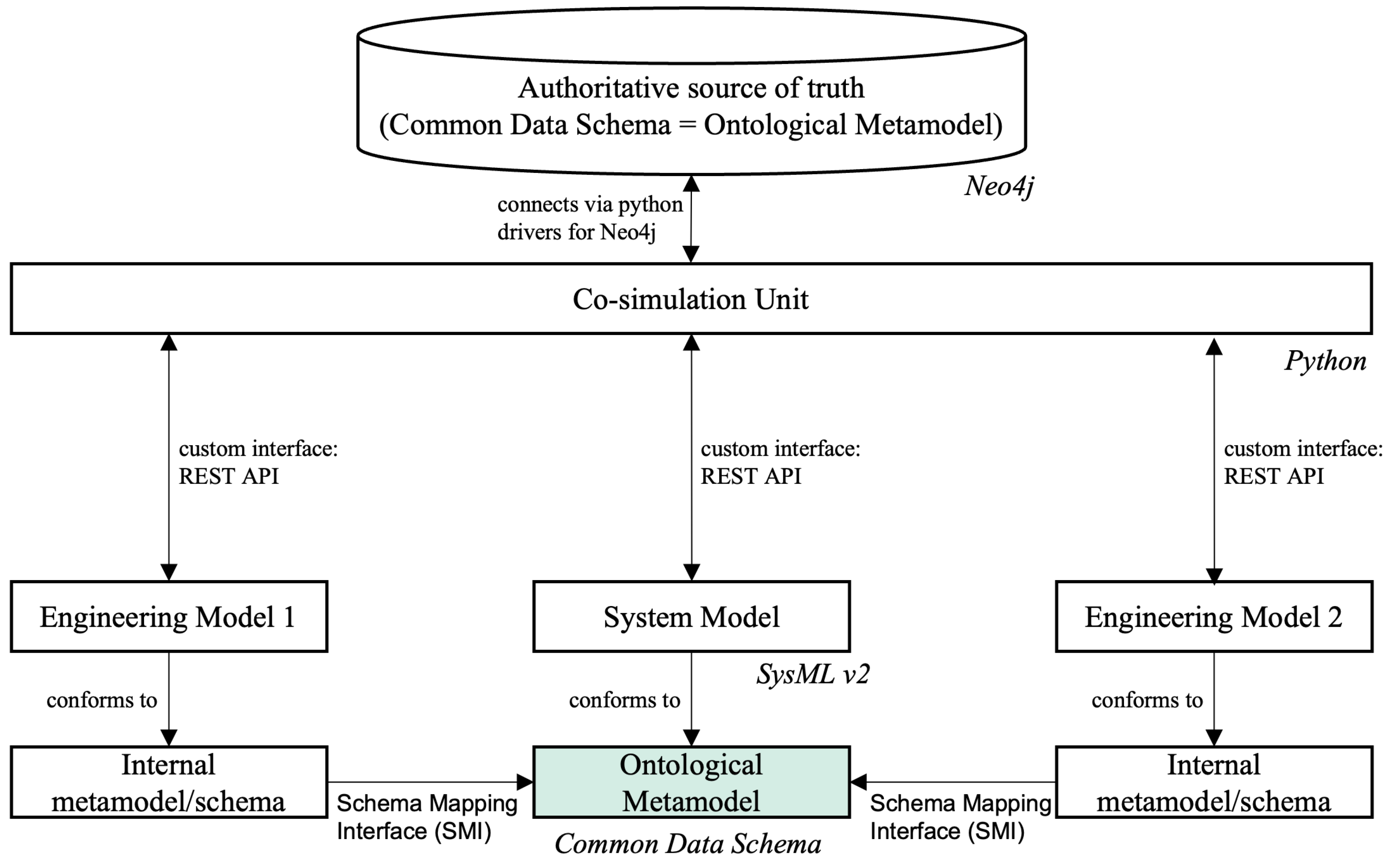
Figure 2.
Propulsion system architecture.
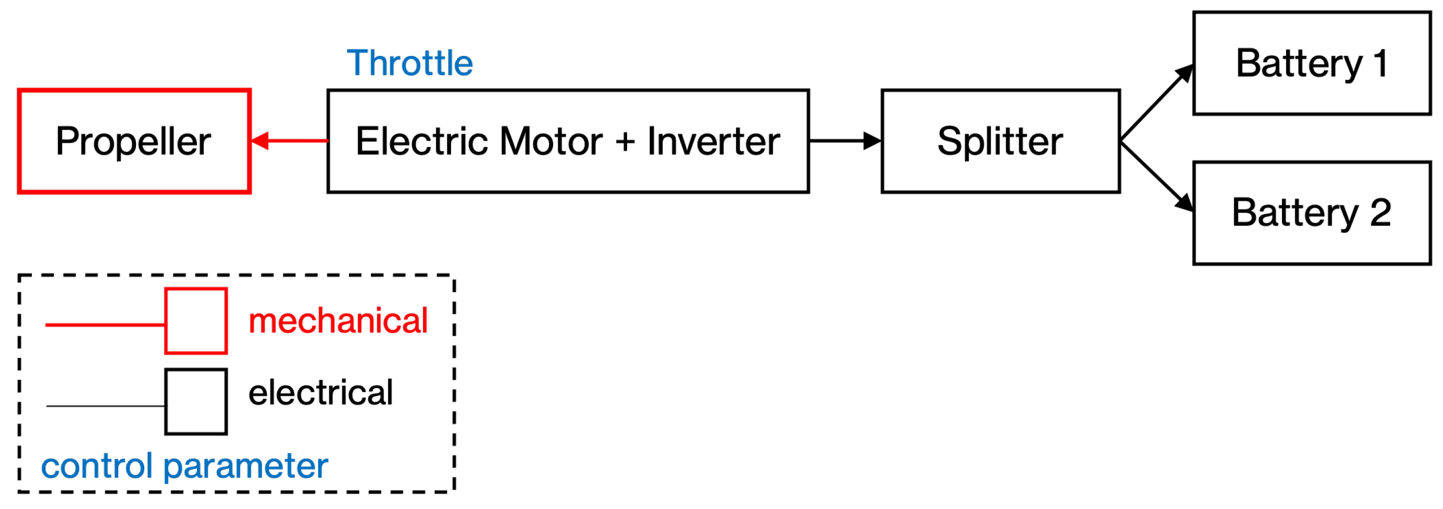
Figure 3.
Mission profile.
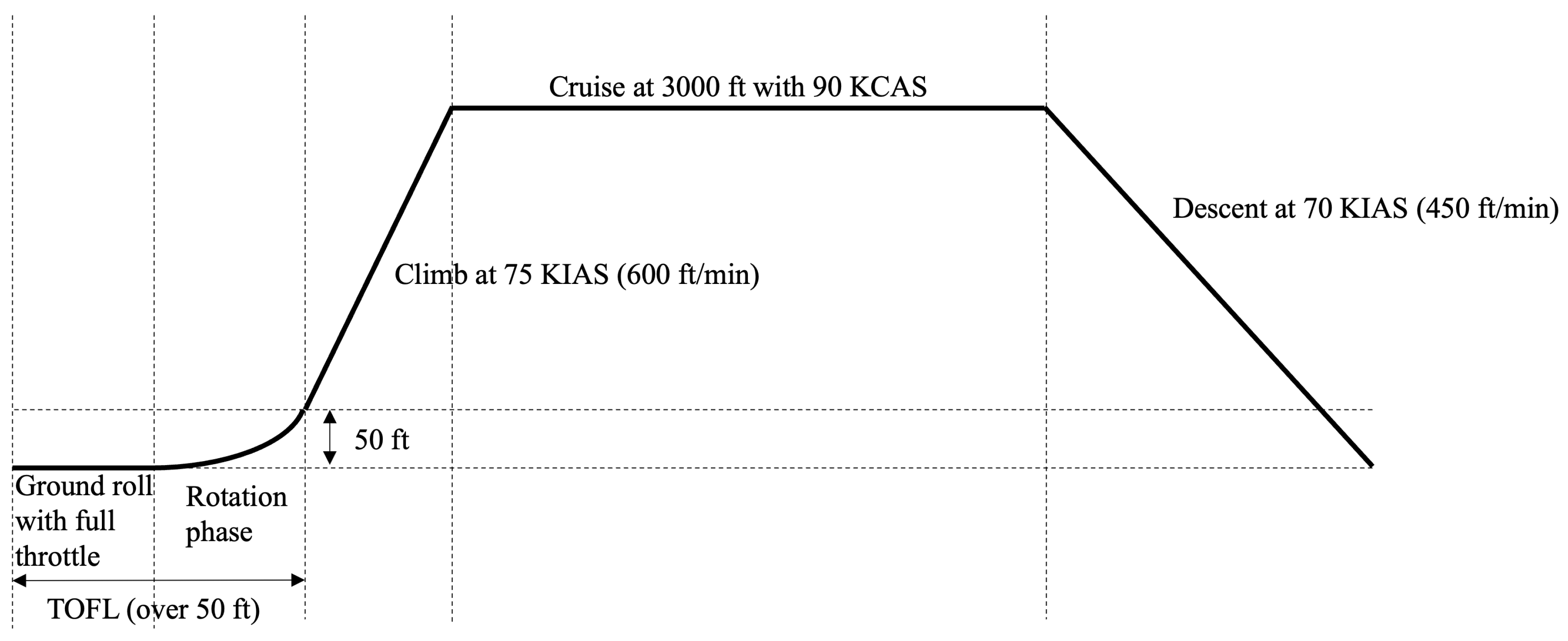
Figure 4.
Propulsion system block definition diagram.
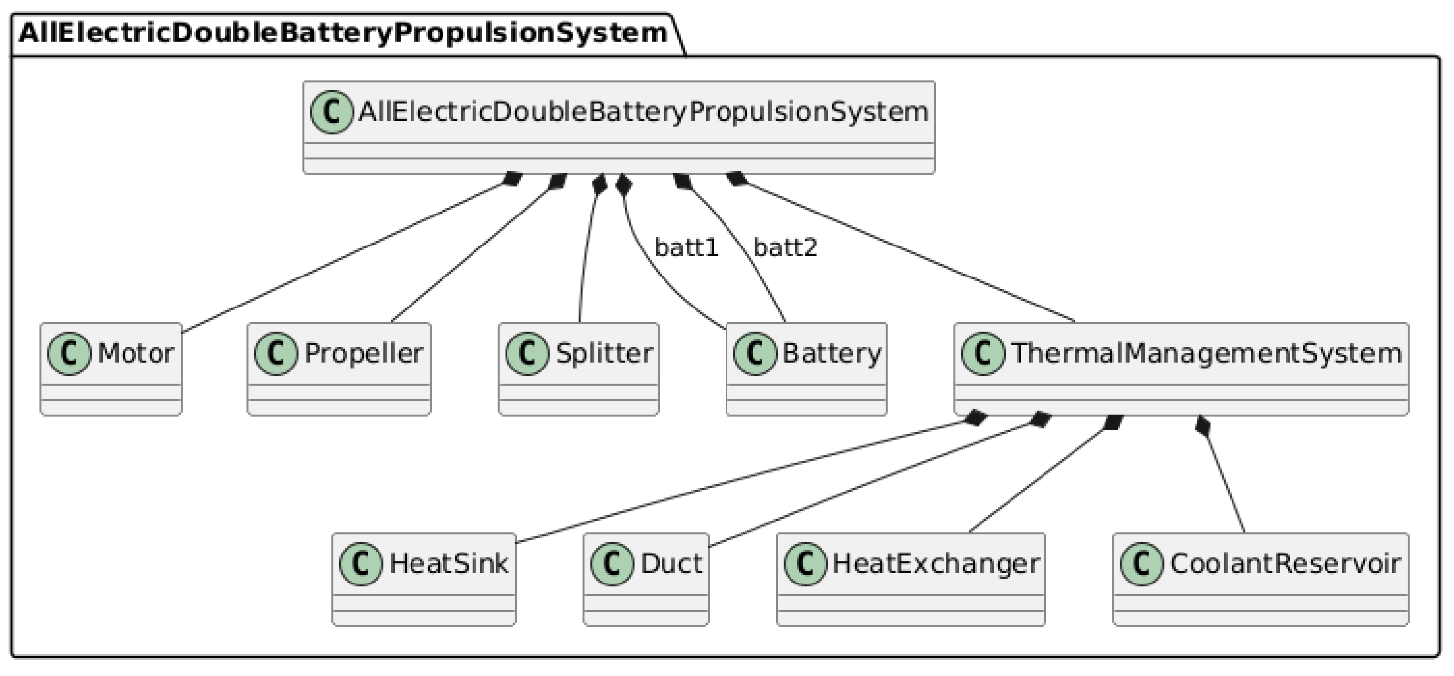
Figure 5.
Propulsion system internal block diagram.
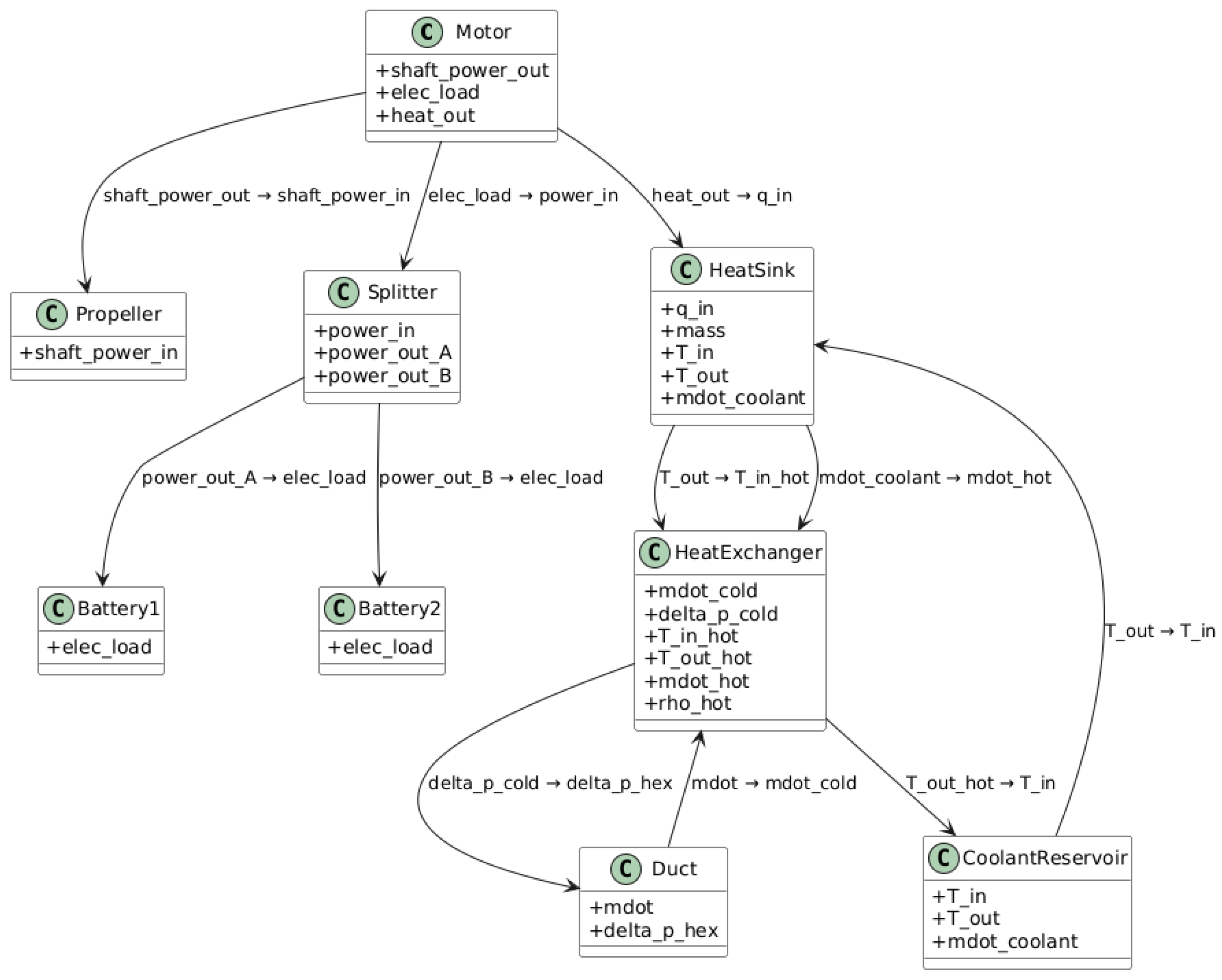
Figure 6.
Architecture and data flow of the co-simulation framework. The SysML v2 model authored in Jupyter Lab is exposed via a custom requirements API. The co-simulation unit retrieves requirements and coordinates MDO analysis and automated requirements verification. Results and traceability information are stored in Neo4j for downstream analysis.
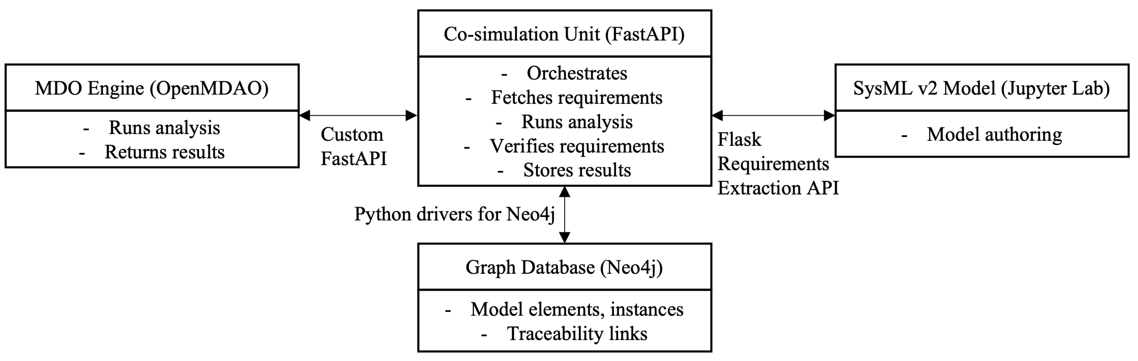
Figure 7.
Architecture and data flow of the co-simulation-enabled requirements verification framework.
Figure 7.
Architecture and data flow of the co-simulation-enabled requirements verification framework.
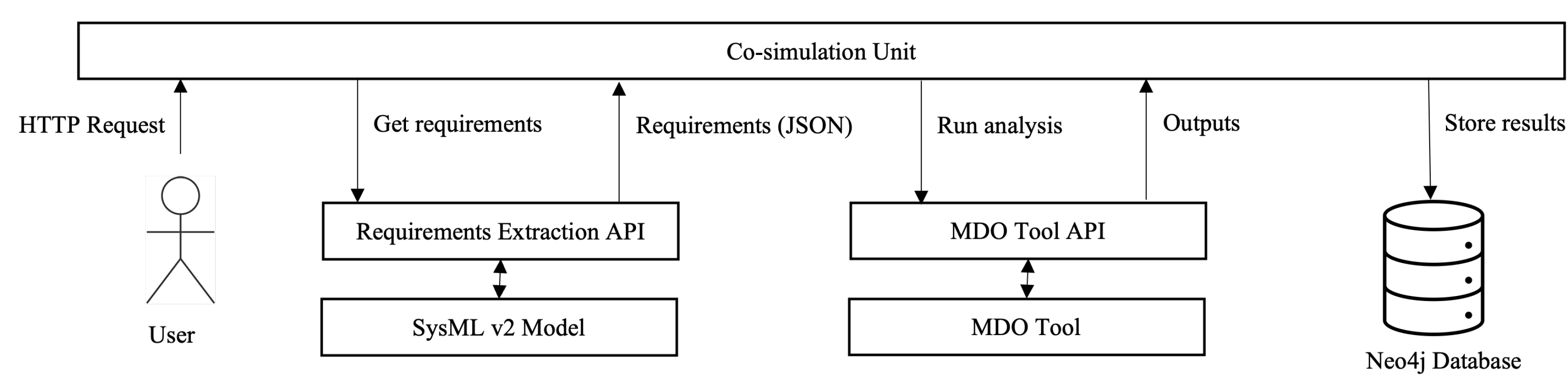
Figure 8.
Mission analysis representation in SysML v2.
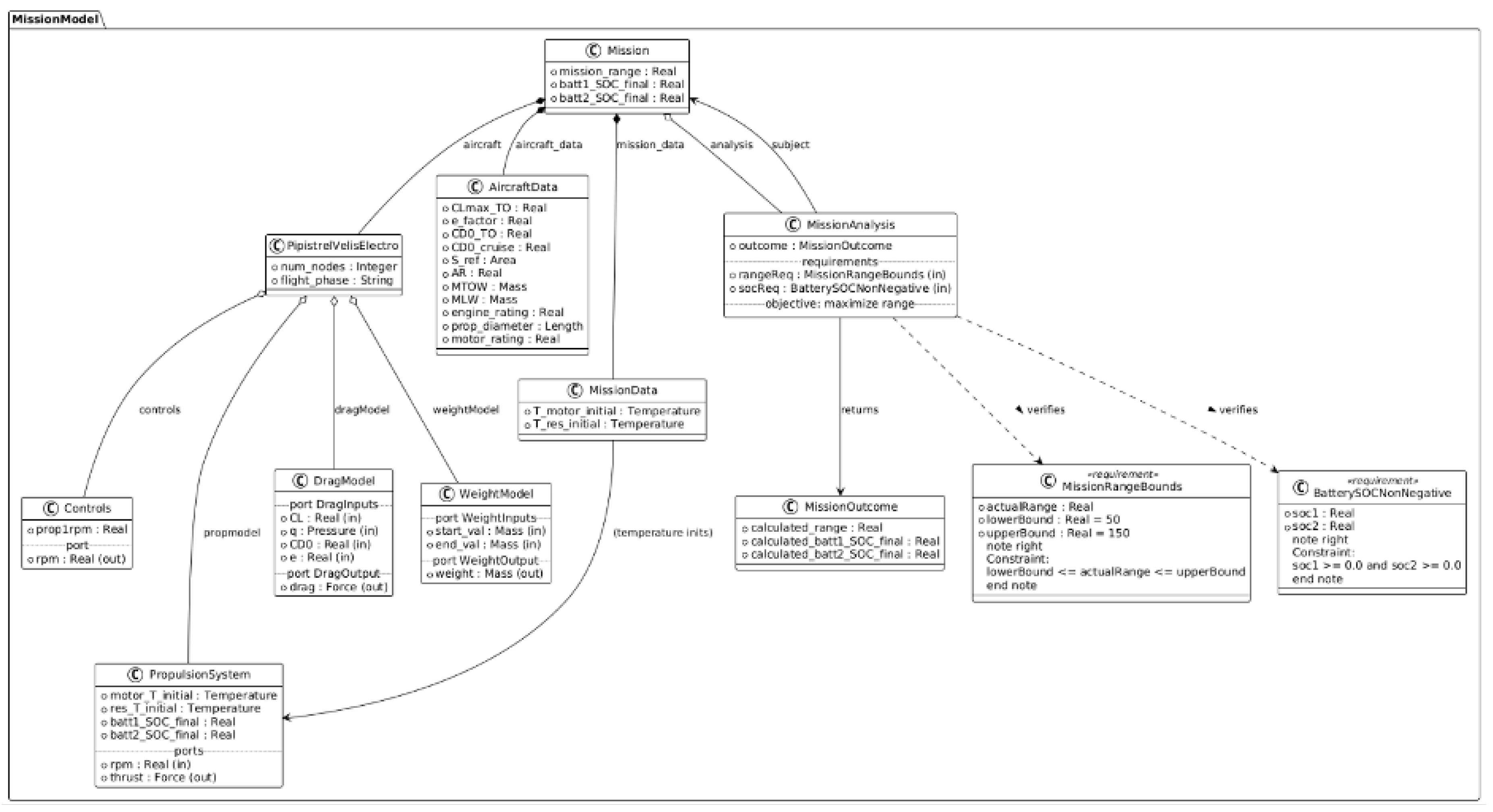
Figure 9.
Representation of requirements verification and traceability in the Neo4j graph database.
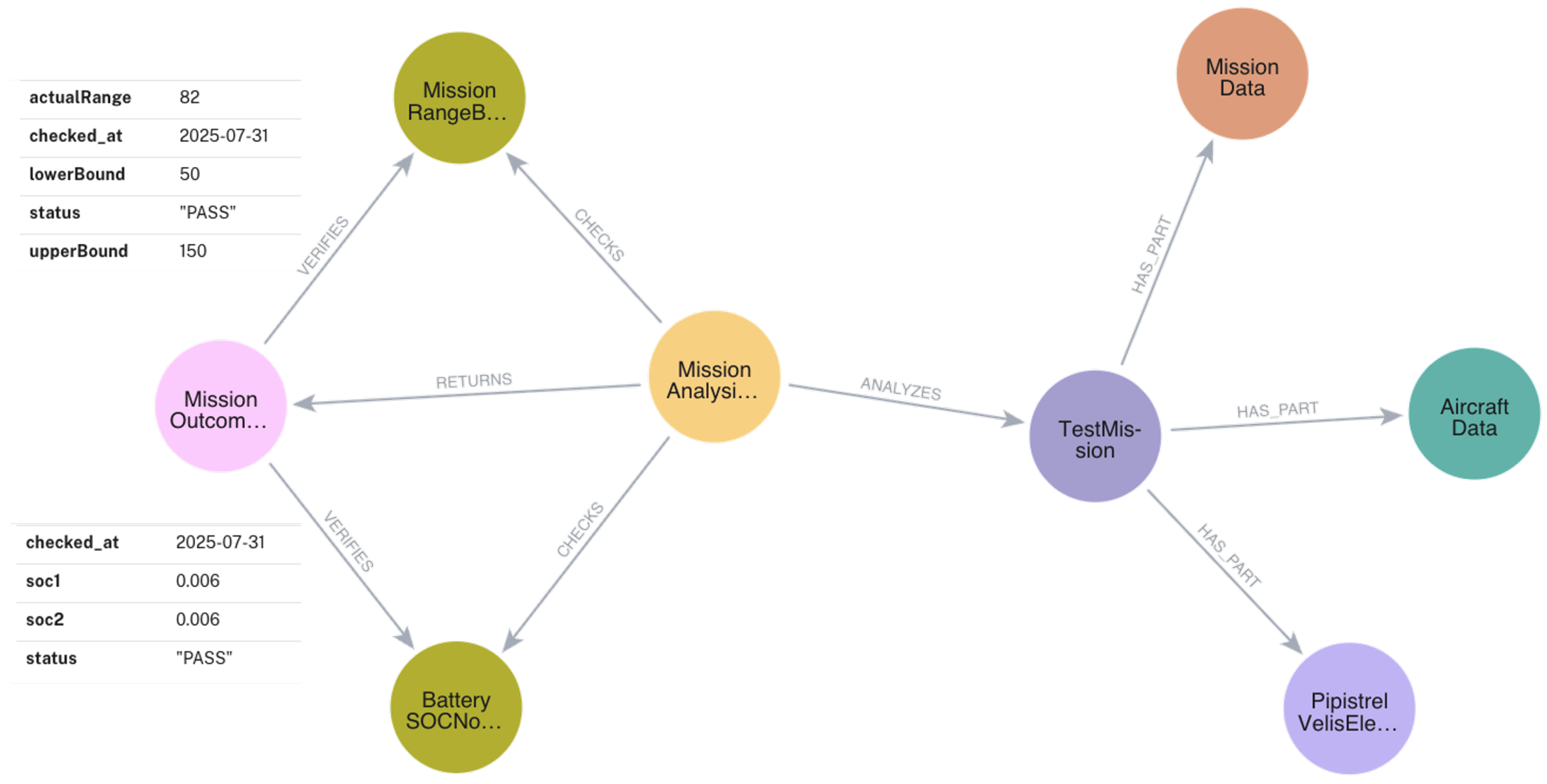

Table 1.
Comparison of representative integration approaches. Note: Major commercial tools are not included in this table; only academic and open-source frameworks are compared.
Table 1.
Comparison of representative integration approaches. Note: Major commercial tools are not included in this table; only academic and open-source frameworks are compared.
| Reference | Integration Approach | Analysis Integrated | Common Data Schema | Application Context | Results Feedback |
|---|---|---|---|---|---|
| AGILE/ AGILE4.0 | Semantic mapping, middleware | MDO framework | Yes | Collaborative aircraft design | Semi-automated |
| Hossain et al. (2022) | Executable SysML workflow | MATLAB, OpenMDAO (script-based) | No | UAV system design | Manual |
| Habermehl et al. (2022) | Executable SysML workflow | External custom tool | No | Electric coolant pump design | Manual |
| Schumacher et al. (2022) | Standardized data mapping (XMI, STEP AP 233/242); manual integration | None (static mapping) | Yes | SysML–CAD model integration | None |
| Aïello et al. (2022) | Manual data transfer | MDO framework | No | Drone battery sizing | Manual |
| Fouda et al. (2024) | Custom middleware | GEMSEO | No | Medical drone | Semi-automated |
| Gazaix et al. (2024) | Custom middleware | GEMSEO | No | Wing–engine pylon–nacelle optimization | Semi-automated |
| Dunbar et al. (2023) | Custom middleware | Multiple analysis tools | Yes | Catapult system | Semi-automated |
| Wu et al. (2025) | Custom middleware | Heterogeneous tools | Unified metamodel | Landing gear system | Automated |
| Zhang et al. (2023) | Custom middleware | MDO framework | No | Hydrogen-powered aircraft | Manual |
| Bruggeman et al. (2023) | Custom middleware | MDO framework | Yes | Aircraft conceptual design | Automated |
| Castellano (2025) | Custom middleware | Python scripts & simulation | SysML v2 schema | Space systems | Automated |
| Grunenwald et al. (2025) | Custom middleware | SysML–BPMN decision support | SysML v2 schema | Wind turbine | Automated |
| Chu et al. (2022) | Model to text transformation | Simulink/System Composer | No | Robotics/mechatronics | Manual |
| Lucas et al. (2023) | Python toolkit for SysML v2 | Data analysis exposure | Yes | MBSE tool interoperability | Semi-automated |
| Madni (2021) | Co-simulation | Multiple simulation and test platforms | No | Multi-UAV swarms | Semi-automated |
| Hällqvist et al. (2022) | Standards-based co-simulation (SSP/FMI) | OMSimulator, Modelica | Yes | Aircraft vehicle system development | Automated |
| OpenMBEE | API-based middleware | Multiple tools | Custom schemas | Large systems engineering, multi-tool MBSE | Semi-automated |
| Parameter | Value | Unit |
|---|---|---|
| Maximum Takeoff Weight (MTOW) | 600 | kg |
| Empty Weight | 428 | kg |
| Wing Reference Area () | 9.51 | m2 |
| Aspect Ratio (AR) | 12.0 | – |
| Motor Power Rating | 57.6 | kW |
| Battery type | Pipistrel PB345V124E-L | – |
| Battery Capacity (total) | 24.8 | kWh |
| Battery Pack Mass (each) | 70 | kg |
| Propeller Type | Pipistrel P-812-164-F3A, fixed-pitch | – |
| Propeller number of blades | 3 | – |
| Propeller diameter | 1.64 | m |
| Certification | EASA type-certified | – |
Table 3.
Mapping of OpenMDAO Constructs to SysML v2 Constructs.
| OpenMDAO Construct | SysML v2 Construct | Description |
|---|---|---|
| Group | part definition | System/subsystem assembly |
| Component (Explicit/Implicit) | part definition | Physical or logical component |
| Variable | attribute | Model parameter or state variable |
| Input/Output | port definition | Interface for flow/data exchange |
| Physical Flow (air, coolant, etc.) | item definition | Fluid/material/energy carried by ports |
| Connection/wiring | connect statement | Connection between ports/flows in system context |
| Hierarchy | nested part definition | System decomposition/containment |
| Computation/Behavior | logical part/activity | (Optional) For detailed logic/analysis representation |
Table 4.
Automated requirements verification results for the Velis Electro case study.
| Requirement | Constraint | Calculated Value | Status |
|---|---|---|---|
| Mission Range Bounds | NM | 82 NM | Pass |
| Battery SOC Non-Negative | 0.6% | Pass | |
| Battery SOC Non-Negative | 0.6% | Pass |
Disclaimer/Publisher’s Note: The statements, opinions and data contained in all publications are solely those of the individual author(s) and contributor(s) and not of MDPI and/or the editor(s). MDPI and/or the editor(s) disclaim responsibility for any injury to people or property resulting from any ideas, methods, instructions or products referred to in the content. |
© 2025 by the authors. Licensee MDPI, Basel, Switzerland. This article is an open access article distributed under the terms and conditions of the Creative Commons Attribution (CC BY) license (http://creativecommons.org/licenses/by/4.0/).
Copyright: This open access article is published under a Creative Commons CC BY 4.0 license, which permit the free download, distribution, and reuse, provided that the author and preprint are cited in any reuse.


