
Submitted:
31 July 2025
Posted:
01 August 2025
You are already at the latest version
Abstract
This article presents a compact tip-tilting platform designed for hardware-in-the-loop emulation of spacecraft relative dynamics and a physical setup for testing tethered systems. The architecture consists of a granite slab, supported by a universal joint and two linear actuators to control its orientation. This configuration allows a Floating Spacecraft Simulator to move on the surface in a quasi-frictionless environment under the effect of the gravitational acceleration. The architecture includes a dedicated setup to emulate tethered satellite dynamics, providing continuous feedback on the tension along the tether through a mono-axial load cell. By adopting the Buckingham “π” theorem, the dynamic similarity is introduced for the ground-based experiment to reproduce the orbital dynamics. Proof-of-concept results demonstrate the testbed’s capability to accurately reproduce the Hill-Clohessy-Wilshire equations. Moreover, the results of the deployed tethered system dynamics are presented. The paper also details the system architecture of the testbed and the methodologies employed during the experimental campaign.
Keywords:
Hardware-In-the-loop Testbed
; Floating Spacecraft Simulator
; Tethered Satellite Systems
; Real-time Control Algorithms
1. Introduction
Ground-based testbeds play a crucial role in validating and testing all spacecraft at the hardware and software level and for operational procedures before in-orbit commissioning. Ground tests help identify potential problems and optimize system performances in a controlled setting, reducing mission risks and costs [1,2,3,4,5]. In this context, simulations in environments that emulate space conditions are essential, especially when leading experiments on the attitude and orbital dynamics of space systems, which are required to ensure mission success [6].
There are currently different methods for emulating microgravity conditions, such as drop towers, parabolic flights, and sounding rockets, which still offer reduced gravity conditions, respectively, of up to 10 seconds, 25 seconds, and more than 1 minute [7,8,9,10].
Alongside these facilities, the space-flight environment can offer longer microgravity conditions. The International Space Station often carries special laboratories for conducting scientific research, in similarity to the Space Shuttle until its retirement [10].
Another method to emulate microgravity is represented by the air-bearing platforms, which rely on reducing the friction on the involved table [7,11]. These systems are used for validating Guidance, Navigation, and Control (GN&C) algorithms in proximity operations, formation flying, rendezvous, and docking manoeuvres [12,13,14,15,16]. Air-bearing testbeds are based on having a reduced-scale Floating Spacecraft Simulator (FSS) moving on an accurately levelled and smooth surface. In this paper, an air-bearing platform for emulating orbital dynamics is presented. The testbed is based on controlling the attitude of the granite slab, which can be tip-tilted using two linear actuators and one universal joint. This setup allows the non-actuated FSS to respond to the granite surface inclination with reactiveness, effectively replicating accelerations being similar to those a satellite would experience in orbit. This work builds up on the prototype proposed by Ogundele et al. [17].
The main advantage of the testbed is that continuous accelerations can be reproduced on the non-actuated FSS. Unlike state-of-art setups, in which thrusters are onboard the floating platform and impulsive forces are generated, the proposed configuration allows the emulation of non-impulsive forces, effectively simulating disturbances that are continuously acting on satellite systems in orbit.
The present work also introduces the integration of a system specifically designed for testing control algorithms oriented to tethered satellite systems. In detail, the floating platform is also equipped with a tether which is connected to a load cell to measure its tension. The load cell is mounted on a vertical support on a linear guide, enabling dynamic simulations of tethered satellite systems during different operational phases. This setup is developed with a different approach with respect to previous research on testing tethered satellite systems on ground-based frictionless tables [18,19,20]. The proposed architecture leverages the capability of a novel tip-tilting facility to reproduce continuous and precise accelerations.
The paper is organised as follows: The architecture of the testbed is introduced in Section 2. The mathematical and on-orbit modelling, on which the testbed is based, are described in Section 3. To demonstrate the testbed working capabilities, a test campaign is conducted, described in Section 4. Numerical results of the experimental campaign are presented and discussed in Section 5. Finally, conclusions are resumed and drawn in Section 6.
2. System Architecture
This section introduces the testbed, which is subdivided into the following subsystems: the Floating Spacecraft Simulator (FSS), an air-bearing scaled and simplified model that represents the satellite; the Floating Platform (FP), which includes the granite slab, the actuator system, and the laser sensors, standing as central stage on which the FSS operates; the Motion Capture System (MCS), the Tether Testing System (TTS), and the Master Console (MC). The principal units of the testbed are represented in the breakdown tree in Figure 1, while Figure 2 shows the setup of the testbed.
2.1. Floating Platform
The FP is shown in Figure 3. It features a polished granite slab (1), tilted by two linear actuators (2). Laser sensors (3) can be used to measure the relative attitude of the granite surface. The proper kinematics of the mechanism is then ensured by one spherical joints’ couple, which links the linear actuators to the slab, and a universal joint (4). This setup enables the slab to be tilted around two axes, allowing a rigid body positioned on the granite table to experience a simulated gravitational force.
Granite is identified as the most suitable material for the slab, as an extremely flat and smooth surface is required for air-bearing platforms. The granite slab, manufactured by Zali Precision, is polished with high precision, resulting in very low surface roughness and high surface flatness. Moreover, it has great rigidity and high thermal stability. In this way, it does not warp or expand with temperature changes. Furthermore, unlike metal, granite has good damping properties, helping to absorb vibrations to avoid oscillations.
The linear actuators, LGA56 – Captive linear actuator – NEMA 23 by Nanotec, are powered by a power supply unit and actuated via motor controllers, C5-E series by Nanotec, which communicate with the MC via Modbus TCP protocol. The testbed is also equipped with three laser sensors, optoNCDT-1220 of Micro-Epsilon series, working in VIS-RF (VISible RadioFrequency, red semiconductor laser). Lasers are used to measure the relative displacement of three points on the tilting surface with respect to the reference plane. Those three points can be used to evaluate the attitude of the table. The motors and lasers are placed on a steel base attached to the bottom of the support frame, as shown in Figure 3. The specifics of each equipment are reported below in Table 1.
2.2. Floating Spacecraft Simulator
The Spacecraft Simulator developed at Politecnico di Torino [21] is a revised version of that designed and tested at the Naval Postgraduate School of Monterey in 2022 [22]. The FSS is always characterized by a pneumatic subsystem and an air-bearing, shown in Figure 4. It can move on the monolithic granite slab depending on the adopted control strategy. The structure is composed by a 3D printed tank container, an air bearing, and a 3D printed component to fix the tether anchor point, to let the markers being placed to track the FSS through the optical capture system. The pneumatic subsystem, schematized in Figure 5, includes valves and gauges to regulate and measure air pressure, an air-tank, and a manual valve that allows compressed airflow to reach the bearing. The prenumatic system is needed to create an air film between the FSS and the matching plane to establish a quasi-frictionless environment. The air-tank operates at 200 bar (3000 psi) and has a volume of L.
It has a built-in regulator that delivers air at a pressure of 60 bar (800 psi), with maximum utilisation pressure of about 310 bar (4500 psi). Since the air bearing works at an operating pressure of bar, an additional pressure regulator is fed by the air directly coming from the high-pressure one. The output pressure can be monitored by a low-pressure gauge. The pressure relief knob is attached to the low-pressure regulator to regulate it to a desired value, and a manual valve that allows the airflow to be simply shut off or enabled. The air-bearing is flat and round, with a diameter of 65 mm. The entire apparatus weighs approximately 1 kg, taking into account both the tank container and the air bearing, whereas the air-tank has an approximate operative time equal to 1 hour, between recharges, for supporting experiments’ phases.
As already described, around the 3D printed container are fixed four high-reflective markers to let the motion capture system track the FSS on the granite monolith. Eventually, the boulder low-pressure regulator allows the insertion of an external gauge and guarantees the connection between the opening valve and the below-standing flat air-bearing through the air-hose. The air-tank is refilled by an air compressor that harnesses an Oil-Water separator, a carbon filter rod and one sponge to reduce moisture in the tank as more during recharge.
2.3. Motion Capture System
The MCS is essential for accurately tracking the floating system, which would let precise position control. The system comprises four InfraRed (IR) cameras, OptiTrack Flex-13 series, mounted on tripods. These cameras would enable to observation of the tracked volume, where the table system is positioned, on which the FSS moves. Additional cameras can be easily integrated if needed to expand the tracking volume. Furthermore, tripods can be easily moved to positions that frame different desired areas. To track the position of objects within the volume, special markers are adopted. These markers (bolded points in Figure 6) are placed on the FSS system, allowing its position to be continuously monitored. The information on the FSS displacements and velocities are extrapolated by numerically plotting them over a short period.
2.4. Tether Testing System
The TTS is studied to carry out tests in both deployed (see Figure 7 and Figure 8) and under deployment scenarios (see Figure 9). Two different configurations are proposed, accounting for the two scenarios.
The deployed configuration is studied by a setup comprising an aluminium support structure, a linear guide with an actuated prismatic joint and a load cell, of the LSB-200 series by Futek, for real-time tension measurement. Specifically, two aluminium rods and the linear guide form a U-shaped support structure where an extra aluminium profile is fixed with the load cell attached to it. The tether is then connected to the FSS and the load cell with two knots. In this case, the guide does not allow relative motion, though it ensures alignment and structural support.
The setup for the deploying case needs an actuated spool to provide tension control during the deployment. The setup for this configuration (Figure 9) derives from the desire of keeping the FSS as lightweight as possible, with the aim of maximizing its usage time between two recharges. As a result, both the actuated spool and the load cell, features shown in Table 3, have been mounted on the vertical support, with the tether being wrapped on the actuated spool. Its free-end extends toward the FSS, which houses a passive spool, before being routed back to the vertical support, where it is secured to the load cell. With this setup, it is possible to perform a controlled deployment, where a constant value of tension is achieved by the combined action of the linear guide and the actuated spool. From a dynamic standpoint, the presence of the double cable attached to the FSS should not affect its dynamic response as long as one keeps in mind that the true force acting on the FSS is twice the value measured by the load cell. The deployment scenario is provided as key-finding for future integration to the proposed testbed.
3. Mathematical Models for On-orbit Dynamics
The testbed is developed to study the relative dynamics of two satellites in a closed-proximity configuration, generally defined as target and chaser.
3.1. In-Orbit Dynamical Model
Under the hypothesis that the target moves on a circular orbit and its relative distance is smaller than the target’s orbital radius, the Hill-Clohessy-Wilshire (HCW) linearized equations of motion hold true. The HCW equations are written in the Local-Vertical-Local-Horizontal (LVLH) reference frame shown in Figure 10. The framework at hand is a Cartesian Coordinate System (CCS) centred in the target’s (T) centre of mass, where the axis lays on the radial direction from the primary body to the target; the axis lays on the along-track direction; the axis completes the right-hand triad being perpendicular to the orbital plane, in the same direction of the angular momentum, whereas R the primary body radius. The subsequent Equations of Motion (EoM) are written in Equation (1),
where represents the components of the position vector of the chaser Center of Mass (CoM) with respect to the target’s CoM, expressed in LVLH ccs. Dot notation stands for the derivative with respect to the time .
is the orbital angular velocity of the target spacecraft, is the resultant of forces acting on the chaser and M represents its mass.
3.2. Buckingham theorem and scaled orbital dynamics
To replicate the relative orbital dynamics, on a smaller and compact testbed, it is necessary to scale the HCW equations [23]. Based on [17,24], the dynamic similarity is ensured between the two systems by applying the Buckingham theorem and the principle of similarity. The Buckingham theorem states that if a phenomenon is described by p variables, with q fundamental units involved, the entire system can be expressed using dimensionless parameters, called variables. By imposing equality between the variables of the real case and those of the scaled case, the principle of similarity ensures dynamic similarity between the two [25,26]. The system involves a total of 15 variables:
A new set of variables is introduced for the scaled system:
It is possible to recognize that there are three fundamental units: length, mass, and time. As a consequence, a total of 12 variables can be identified and used to establish the similarity conditions between the two systems. The final result is shown in the system of equations Equation (2). In detail, the scaling factors for the three fundamental quantities, namely , , and , are defined as the ratio between the real case and the scaled variables.
The scaling parameters for the derived quantities involved, such as velocity, acceleration, force, and mean motion, are then evaluated as a function of the fundamental ones. According to the Buckingham theorem, all scaling factors can be written as a function of the three factors referring to the fundamental units. In other words, when a test shall be performed, it is sufficient to set only , and to obtain all the scaled quantities involved with the phenomenon. By substituting relations within Equation (2) in Equation (1), the system of Equation (3) is obtained in a testbed-fixed reference frame coordinates that will be defined in the next paragraph.
where is the sum of the control action and the disturbances.
3.3. Testbed system and models
The novel idea behind the proposed testbed is that the plane on which the FSS can freely move is actuated, generating accelerations on the FSS by tip-tilting the matching plane. This section explores the connection between the actuators’ displacements and the acceleration induced on the FSS due to the resulting plane inclination. For the purpose of this calculation, a new reference frame is introduced. As shown in Figure 11, which illustrates the plant of the granite, and are the points where the two linear actuators are mounted, is the point where the pillar is mounted, d is the distance between the two actuators, l the distance between any of the actuators and , and p and q the sides of the slabs. The new CCS is fixed to the granite slab, centred on the rotation pole of the system , and orientated with axis parallel to p, parallel to q, and axis completes the right-hand triad.
It is now essential to determine the relationship between the actuators’ displacements, and the acceleration induced on the FSS. This relationship has already been established by [17,24], and only the most relevant results are discussed here.
The position of points and are respectively
Using a Euler angle and axis parametrization, when a small displacement is applied, a rotation of is made around the vector , see Figure 12.
The new attitude of the matching plane is expressed by the Direction Cosine Matrix (DCM) in Equation (5).
When a displacement is applied, a rotation of around is triggered and the subsequent DCM is obtained in Equation (6), see Figure 13.
Finally, the attitude of the table after two generic rotations can be expressed as the matrix multiplication of the two DCMs. Assuming the hypothesis of small displacement holds, the second or higher order terms are neglected. The resulting matrix is obtained in Equation (7).
As a consequence, the gravitational acceleration experienced by the FSS in the reference frame of the table is determined by Equation (8).
As shown in Equation (8), the acceleration along is dependent only on the gravitational acceleration, which is balanced by the plane’s normal force, while the other two components are related to the movement of actuators. For this reason, Equation (9) can be written.
By inverting Equation (9), it is possible to write the table’s steering law in Equation (10), which represents the required displacements that are necessary to obtain the desired acceleration components .
Knowing the relations between the displacements of both the actuators and the accelerations experienced by the FSS due to tilting the granite slab, it is possible to obtain a surface-map of the reproducible acceleration. As shown in Figure 14, the acceleration a, which is the norm of the vector , can be plotted as a function of and , individuating the accelerations that can be reproduced on the table. In detail, knowing the characteristics of the actuators, resumed in Table 1, and imposing a security coefficient that limits their strokes to 30 mm (± 15 mm), the maximum and minimum reproducible accelerations are determined, reported in Table 4.
The map in figure Figure 14 refers to an ideal case where the supporting structure where the actuators are mounted is perfectly flat. However, taking into consideration [18], the testbed may present a slight residual inclination. That may be caused by all the necessary manufacturing processes that might have plastically deformed the structure at the micrometric level. For this reason, a worst-case scenario with an expected residual acceleration of the order of magnitude of the minimum reproducible value of m/s2 is considered.
4. Test Campaign
The test campaign is crucial for the testbed. In detail, the campaign is planned not only to conduct a test related to the dynamic control of a tethered system, but also to validate the apparatus. In detail, to assess the capabilities and the performance of the tip-tilting testbed, a first test is conducted to verify that the system is able to work in closed-loop, autonomously responding to inputs on the system, while a second test is planned to assess the performance of reproducing the orbital dynamics of Hill-Clohessy-Wiltshire equations.
4.1. Closed-Loop Calibration
The first test aims to control the granite table’s attitude, achieving a horizontal configuration. In order to do that, a closed-loop approach is implemented via a Proportional Integrative Derivative (PID) controller [27]. By tracking the FSS’s position and velocity with the MCS, the goal is to guide it towards the middle point of the granite surface with zero velocity. As a result, the control action imposed by the table is evaluated by Equation (11):
where and represent the desired final position and velocity. , , are the gain matrices needed to compute the PID controller.
The acceleration calculated in real-time with Equation (11) is then transformed into information on the displacement and fed into the plant. The evolution of the dynamics in terms of position and velocity is then extracted by the motion capture system and used as feedback for the control law. The schematic in Figure 15 summarizes the process.
4.2. Emulation of Linearized Relative Dynamics
The objective of this test is to evaluate how accurately the testbed can replicate the orbital relative dynamics governed by the HCW equations of motion. For this case study, orbital perturbations are neglected, and the motion is analysed solely within the orbital plane. As a consequence, the system in Equation (1) is reduced to 2 degrees of freedom and the external forces are set to zero, obtaining the set of coupled differential equations in Equation 12 with the initial condition of .
To set up the experiment, it is necessary to relate the LVLH CCS with the table-fixed CCS. Without loss of generality, the and are set to be coincident with and . Secondly, scaling factors are to be selected. In particular, after propagating the real system trajectory and defined and , they can be used to evaluate the . Specifically, to guarantee that the FSS does not exceed the table’s boundaries, the constraint in Equation (13) shall be respected.
Additionally, a constraint must also be set on acceleration. Indeed, as seen in Section 3.3, a residual acceleration of the order of magnitude of 0.0025 m/s2, see Table 4, is considered. To replicate the relative dynamics governed by the HCW equations of motion (EoM) in the absence of control, it is crucial to ensure that residual accelerations do not significantly alter the FSS dynamics. Moreover, the scaled accelerations should also not be greater than the maximum reproducible value in Table 4. To mitigate these risks, the constraints in Equation (14) are enforced, ensuring that the scaled HCW acceleration is dominant over unwanted perturbations.
As the scaling factors are chosen, the equations of HCW dynamics are scaled, allowing to write Equation (16).
A new Matlab/Simulink script is developed, and the workflow is shown in Figure 16.
4.3. Fully-Deployed Tether Dynamics
The objective of the third experiment is to test the dynamics and control algorithm of a novel cross-track tethered satellite system. Unlike a conventional tethered spacecraft that primarily exploits the gravity gradient torque for radial alignment, the system of interest consists of two satellites connected by a tether that is extended along the cross-track direction ( axis in the LVLH reference frame, Figure 17). In this configuration, the tethered system maintains a perpendicular orientation to the orbital plane. This orientation is particularly suited for remote sensing applications, especially for radar imaging, since multiple radar instruments can be positioned along the tether, obtaining a distributed radar configuration [28]. A key advantage of this architecture is its potential to minimize propellant consumption for formation flying [28]. While similar tethered configurations have been proposed for applications such as position keeping and rendezvous maneuvers [29], the present configuration introduces a novel tethered system concept, where the tether is maintained in cross-track orientation by generating control forces, using thrusters, or aerodynamic drag plates if the spacecraft is flying at Very-Low Earth Orbits (VLEOs) altitude [30]. The TSS is composed of two CubeSat platforms which are connected by a tether with a length that can reach hundreds of meters. If the spacecraft operates in VLEO, each satellite is equipped with two triangular-shaped drag plates designed to interact with the residual atmospheric environment [31], generating control forces that mitigate external disturbances and maintain the tether in a tensioned state, thereby stabilizing the formation. If no residual drag can be exploited, thrusters can be used to stabilize the spacecraft system. The system dynamics is analysed within the LVLH reference frame. The main goal is to assess the testbed’s ability to accurately replicate the orbital dynamics of a TSS in a cross-track configuration.
Specifically, considering the system in circular orbit at an altitude of 500 km, where a tether of 100 m is connected to two CubeSat platforms of 20 kg and is kept in tension by thruster propulsion, and with an initial off-nominal condition where the two satellites are misaligned with respect to the across-track direction, the controller is tasked with correcting the positional error and restoring proper cross-track alignment. Additionally, once the satellites are correctly positioned, the controller is designed to maintain constant tension along the tether.
For the experimental campaign, the TTS-deployed configuration is used (see Figure 7). The setup allows for the simulation of half of the cross-track tethered satellite, where the dynamics of just one CubeSat is analysed. The CCS is centred on the load cell, at one end of the testbed tether, which corresponds to half of the TSS. The CCS, with respect to the reference frame in Figure 11, is oriented with , , and axes concordant, respectively, with , , and vectors. As the radial and cross-track directions lie down on the matching plane, the dynamics along is not considered, and the HCW equations of motion are reduced to two degrees of freedom (Equation (17)):
where and are the control actions, while and are the components of the tension along the tether.
Given the order of magnitude of the acceleration involved and the brief time interval in which this phenomenon unfolds, a simplified model, where disturbances are neglected, is assumed.
The along-track motion on is neglected, and the accelerations due to the control ( and ) and the presence of the tether tension ( and ) are considered. During the experiment, a physical tether connected to the FSS introduces the tension, with the architecture described in Section 2.4, while the granite matching plane actuation replicates the joint effect of the HCW and the control. Also in this case, the system requires scaling, and the same approach of section Section 4.2 is implemented.
4.3.1. LQR Controller
A Linear Quadratic Regulator (LQR) controller [27] is designed based on the linearized HCW EoM and a linearized model for the effect of tether on the dynamics. Specifically, the system is represented by the following system:
where and represents the state and input matrices obtained by writing Equation (17) in matrix form, is the disturbance matrix, related to the effect of the tension on the dynamics and is the control input. In particular, to design the controller, a linear, elastic model is assumed for the tether, hence giving:
where E is the Young’s modulus, S and represent the cross-sectional area and the nominal length of the tether respectively, and is the linear deformation. The optimal LQR controller is in the form , where is built as to minimize the following cost function:
and are two user defined weight functions. For the sake of completeness, two different matrices are defined, as there are two possible states the system can be in. When the cable is slack, the spacecraft’s dynamics can be described purely by the HCW EoM, while when there is tension in the tether, the elastic force must also be added. The matrices , and for the two cases are obtained as shown in Equation (21) and Equation (22) respectively.
5. Numerical and Experimental Results
In this section, the numerical results of the test campaign are reported and discussed.
5.1. Closed-LOop Calibration
To test the calibration loop described in Section 4.1, the gains are defined after a few iterations of trial and error, as in Equation (23):
where is the identity matrix of second order. The desired final state is set to and where the notation from Section 4.1 is kept. The results are shown in Figure 18.
The system reaches the desired state within 0.5 millimetres after approximately 20 seconds, with final actuator chattering in the order of their resolution. This behaviour suggests that it is impossible for the setup to achieve a perfect horizontal attitude, due to the limited resolution of the actuators. As a result, the FSS is expected to experience a residual acceleration of approximately m/s2.
5.2. Emulation of Linearized Relative Dynamics
The evolution of the dynamics of two satellites starting from different radial positions, with zero velocity, is studied using the HCW equations, as explained in Section 4.2. In particular, a starting state of is chosen. The resulting trajectory and acceleration after propagating for 20% of the orbital period are shown in Figure 19 and Figure 20.
The maximum displacement is m, while the acceleration m/s2. Consequentially, according to the criteria expressed in Section 4.2, the scaling factors are selected as:
Figure 21 shows that the experimental results match the numerically propagated trajectory with a reasonable error. By increasing the number of the test and considering the average, spurious errors are mitigated. They are caused by various factors, such as the residual friction between the FSS and the matching plane and minor surface defects.
Figure 22 shows the relative error between the numerically propagated trajectory and the experimental results. This error is computed as the norm of the difference between the vectors’ positions at the same instant of time. These results highlight that the testbed can emulate relative dynamics with a maximum error of mm; it corresponds to an error of 5.5 m when scaled back up to the real case scenario, which is in line with the hypothesis of a residual acceleration of approximately 2.25 mm/s2.
5.3. Fully-Deployed Tether Dynamics
The case study for the third test regards a 100 m long tether, starting from an off-nominal slack condition with the goal of testing the ability of the LQR controller (presented in Section 4.3) to lead the system back to a cross-track configuration, and stabilizing it. Moreover, the load cell included in the setup is used to measure the value of tension during the whole experiment.
A scaling factor is selected as the ratio of half of the nominal length of the real case tether and the 1 m cable used in the experiment. As for the , again, a constraint regarding the acceleration range is enforced. Particularly, in this case, only a limit on maximum acceleration is enforced, since the system is now controlled in closed loop and, therefore, it is able to keep the FSS in the desired position, with a final continuous chattering of the actuators, in a similar way to Section 5.1. Specifically, an acceleration profile as that shown in Figure 23 is found, with a maximum value of m/s2, which leads to .
According to these constraints the set of scaling factors is chosen as in Equation (25).
The FSS displacements, shown in Figure 24, stabilize at mm and mm with respect to the origin of the CCS placed on the load cell, observing that the steady-state in position is achieved after approximately 20 seconds of simulation.
In Figure 25, the measured value of tension stabilizes at approximately 1 mN after approximately 80 seconds of the experiment. During an initial phase of uncontrolled rotation of the FSS along its vertical axis, the tether stretches more, increasing the tension. The presence of the tether help stabilize the FSS, gradually damping the amplitude of oscillation closer to 0 degrees. However, since no attitude control is implemented, the rotation of the FSS around its vertical axis does not stabilize to a constant value. Therefore, the tension of the tether is close to its steady state around 1 mN but experiences minor oscillations caused by the rotation.
As a result, the tether contributes to the stability of the system; however, to achieve a more refined attitude, an active control strategy is required.
6. Conclusions
This paper presents a novel hardware-in-the-loop testbed capable of emulating the relative dynamics between two orbiting spacecrafts, along with an innovative experimental setup for tethered satellite systems. The design is detailed, including the derivation of scaling laws based on the Buckingham theorem and the principle of similarity. Experimental results demonstrate the potential of this approach to replicate orbital dynamics within a laboratory environment through a Hardware-In-the-Loop setup. Experiments are carried out to evaluate the capabilities of the testbed to replicate the dynamics described by the HCW equations of motion, as well as the behaviour of a tethered satellite system in a cross-track configuration. Specifically, results show that the FSS follows a trajectory closely matching the one obtained from numerical propagation of the Hill-Clohessy-Wilshire equation. Furthermore, simulations of tether-assisted stabilization indicate that the combined action of the tether and an LQR controller is effective in stabilizing the tethered spacecraft.
7. Patents
The main principle underlying the tip-tilt flat-table facility described in this paper is based on two existing patent inventions:
- 1)
-
"Method and Apparatus for the Stabilization of a Satellite Formation",[31].Description: "The invention relates to a method for stabilization of the orbital motion set-up of a group of satellites bound to a tether. To this end, the tension of the tether that connects two or more satellites is controlled in order to keep them in the desired flight formation. This effect is obtained by perturbing a satellite to generate a tension component in the tether, which results in a recoil force that brings the system back into a condition of equilibrium. According to a preferred embodiment, the tension T of the tether is obtained by adjusting the disposition of one or more aerodynamic surfaces provided on the satellites at the ends of the tether".
- 2)
-
"Dynamically tilting flat table to impart a time-varying gravity-induced acceleration on a floating spacecraft simulator",[32].Description: "Disclosed is a planar test bed comprising a planar surface and further comprising mechanical couplings in mechanical communication with the planar table and the supporting legs. The mechanical couplings are translatable to provide three degrees of freedom for orientation of the planar surface. A processor receives position and velocity information describing an object on the planar surface, and calculates a relative acceleration typically using a function aR=f(t,xR,vR,t). The processor communicates with the mechanical couplings to establish an orientation where a local gravity vector projects onto the planar surface and generates acceleration with magnitude and direction substantially equal to the desired acceleration aR The operations occur in cyclic fashion so the desired accelerations and planar orientations are updated as an object transits over the planar surface".
Author Contributions
Conceptualization, A.P., M.C., M.L.V., C.B., G.G., C.L.M., R.A., S.A., M.R.; methodology, A.P., M.C., M.L.V., C.B.; software, A.P., M.C., M.L.V., C.B.; validation, A.P., M.C., M.L.V., G.G., C.B.; formal analysis, A.P., M.C., M.L.V., C.B.; investigation, A.P., M.C., M.L.V., C.B.; writing - original draft preparation, A.P., M.C., M.L.V., C.B.; writing - review and editing, G.G., C.L.M., R.A., S.A., M.R.; supervision, G.G., M.R.; project administration, G.G., M.R.; funding acquisition, C.L.M., R.A., S.A., M.R.; All authors have read and agreed to the published version of the manuscript.
Funding
This publication is part of the project ASTRO, funded under the Academic PoCs of the NODES Programme, supported by the MUR - M4C2 1.5 of PNRR, funded by the European Union - NextGenerationEU (Grant agreement no.ECS00000036).
Institutional Review Board Statement
Not applicable.
Informed Consent Statement
Not applicable.
Data Availability Statement
The original contributions presented in the study are included in the article; further inquiries can be directed to the corresponding author.
Acknowledgments
The authors would like to thank L. Kalaiselvam, S. Pipolo, P. Vergari, M. De Matteis, M. L. Ottavi, A. V. Atzori, E. Graziano, A. Breda, and A. Milan for their contribution to the design and development of the testbed.
Conflicts of Interest
The authors declare no conflicts of interest.
Abbreviations
| CCS | Cartesian Coordinate System |
| DCM | Direction Cosine Matrix |
| EoM | Equation of Motion |
| FP | Floating Platform |
| FSS | Floating Spacecraft Simulator |
| GN&C | Guidance, Navigation and Control |
| HCW | Hill-Clohessy-Wilshire |
| HIL | Hardware-In-the-Loop |
| MC | Master Console |
| MCS | Motion Capture System |
| LQR | Linear Quadratic Regulator |
| LVLH | Local-Vertical Local-Horizontal |
| PID | Proportional Integrative Derivative |
| TSS | Tethered Satellite System |
| TTS | Tether Testing System |
| VLEO | Very Low Earth Orbit |
References
- Curti, F.; Romano, M.; Bevilacqua, R. Lyapunov-Based Thrusters’ Selection for Spacecraft Control: Analysis and Experimentation. Journal of Guidance, Control, and Dynamics 2010, 33, 1143–1160. [Google Scholar] [CrossRef]
- Romano, M.; Friedman, D.A.; Shay, T.J. Laboratory Experimentation of Autonomous Spacecraft Approach and Docking to a Collaborative Target. Journal of Spacecraft and Rockets 2007, 44, 164–173. [Google Scholar] [CrossRef]
- Wilde, M.; Clark, C.; Romano, M. Historical survey of kinematic and dynamic spacecraft simulators for laboratory experimentation of on-orbit proximity maneuvers. Progress in Aerospace Sciences 2019, 110, 100552. [Google Scholar] [CrossRef]
- Fernandez, B.R.; Herrera, L.; Hudson, J.; Romano, M. Development of a tip-tilt air-bearing testbed for physically emulating proximity-flight orbital mechanics. Advances in Space Research 2023, 71, 4332–4339. [Google Scholar] [CrossRef]
- De Stefano, M.; Mishra, H.; Giordano, A.M.; Lampariello, R.; Ott, C. A Relative Dynamics Formulation for Hardware- in-the-Loop Simulation of On-Orbit Robotic Missions. IEEE Robotics and Automation Letters 2021, 6, 3569–3576. [Google Scholar] [CrossRef]
- Shabana, A.A. Dynamics of Multibody Systems, 1st ed ed.; Cambridge University Press: New York, 2020. [Google Scholar]
- Rybus, T.; Seweryn, K. Planar air-bearing microgravity simulators: Review of applications, existing solutions and design parameters. Acta Astronautica 2016, 120, 239–259. [Google Scholar] [CrossRef]
- Pletser, V.; Kumei, Y. Parabolic flights. Generation and Applications of Extra-Terrestrial Environments on Earth.
- Seibert, G.; Battrick, B.T. The history of sounding rockets and their contribution to European space research; ESA Publications division Noordwijk, 2006.
- Lappa, M. Space research. In Fluids, Materials and Microgravity; Elsevier, 2004; pp. 1–37. [CrossRef]
- Zappulla, R.; Virgili-Llop, J.; Zagaris, C.; Park, H.; Romano, M. Dynamic Air-Bearing Hardware-in-the-Loop Testbed to Experimentally Evaluate Autonomous Spacecraft Proximity Maneuvers. Journal of Spacecraft and Rockets 2017, 54, 825–839. [Google Scholar] [CrossRef]
- Virgili-Llop, J.; Zagaris, C.; Zappulla, R.; Bradstreet, A.; Romano, M. A convex-programming-based guidance algorithm to capture a tumbling object on orbit using a spacecraft equipped with a robotic manipulator. The International Journal of Robotics Research 2019, 38, 40–72. [Google Scholar] [CrossRef]
- Virgili-Llop, J.; Zagaris, C.; Park, H.; Zappulla, R.; Romano, M. Experimental evaluation of model predictive control and inverse dynamics control for spacecraft proximity and docking maneuvers. CEAS Space Journal 2018, 10, 37–49. [Google Scholar] [CrossRef]
- Virgili-Llop, J.; Romano, M. Simultaneous Capture and Detumble of a Resident Space Object by a Free-Flying Spacecraft-Manipulator System. Frontiers in Robotics and AI 2019, 6. [Google Scholar] [CrossRef] [PubMed]
- Boge, T.; Wimmer, T.; Ma, O.; Zebenay, M. EPOS–A Robotics-Based Hardware-in-the-Loop Simulator for Simulating Satellite RvD Operations. In Proceedings of the 10th International Symposium on Artificial Intelligence, Robotics and Automation in Space, August 2010. [Google Scholar]
- Eun, Y.; Park, S.Y.; Kim, G.N. Development of a hardware-in-the-loop testbed to demonstrate multiple spacecraft operations in proximity. Acta Astronautica 2018, 147, 48–58. [Google Scholar] [CrossRef]
- Fernandez, B.R.; Herrera, L.; Hudson, J.; Romano, M. Development of a tip-tilt air-bearing testbed for physically emulating proximity-flight orbital mechanics. Advances in Space Research 2023, 71, 4332–4339. [Google Scholar] [CrossRef]
- Yu, B.; Geng, L.; Wen, H.; Chen, T.; Jin, D. Ground-based experiments of tether deployment subject to an analytical control law. Acta Astronautica 2018, 151, 253–259. [Google Scholar] [CrossRef]
- Yu, B.; Huang, Z.; Geng, L.; Jin, D. Stability and ground experiments of a spinning triangular tethered satellite formation on a low earth orbit. Aerospace Science and Technology 2019, 92, 595–604. [Google Scholar] [CrossRef]
- Mantellato, R.; Lorenzini, E.; Sternberg, D.; Roascio, D.; Saenz-Otero, A.; Zachrau, H. Simulation of a tethered microgravity robot pair and validation on a planar air bearing. Acta Astronautica 2017, 138, 579–589. [Google Scholar] [CrossRef]
- Bologna, F. Design, Integration and Testing of a Small Floating Spacecraft Simulator. Master’s thesis, Politecnico di Torino, 2023.
- Kulke, J. Conceptual Design of an Open-Source Hardware Simplified Floating Spacecraft Simulator. Master’s thesis, Naval Postgraduate School, Monterey, California, 2022.
- Ciarcià, M.; Cristi, R.; Romano, M.M. Emulating Scaled Clohessy–Wiltshire Dynamics on an Air-Bearing Spacecraft Simulation Testbed. Journal of Guidance, Control, and Dynamics 2017, 40, 2496–2510. [Google Scholar] [CrossRef]
- Ogundele, A.D.; Fernandez, B.R.; Virgili-Llop, J.; Romano, M. A tip-tilt hardware-in-the-loop air-bearing test bed with physical emulation of the relative orbital dynamics. In Proceedings of the 29th AAS/AIAA Space Flight Mechanics Meeting, Vol. 168; 2019; p. 3781. [Google Scholar]
- Buckingham, E. On Physically Similar Systems; Illustrations of the Use of Dimensional Equations. Physical review 1914, 4, 345–376. [Google Scholar] [CrossRef]
- Bridgman, P.W. Dimensional analysis; Yale University Press: Connecticut, 1922. [Google Scholar]
- Wie, B. Space vehicle dynamics and control; Aiaa, 1998.
- Aliberti, S.; Quadrelli, M.B.; Romano, M. A distributed space radar sounder using a cross-track flying tethered satellite system. Acta Astronautica 2024, 221, 266–282. [Google Scholar] [CrossRef]
- Bevilacqua, R.; Romano, M. Rendezvous Maneuvers of Multiple Spacecraft Using Differential Drag Under J2 Perturbation. Journal of Guidance, Control, and Dynamics 2008, 31, 1595–1607. [Google Scholar] [CrossRef]
- Aliberti, S.; Quadrelli, M.B.; Romano, M. Dynamics and Aerodynamic Control of a Cross-Track Tether Satellite System. ESA GNC-ICATT 2023. [CrossRef]
- Romano, M.; Aliberti, S.; Apa, R.; Matonti, C.L. Method and Apparatus for the Stabilisation of a Satellite Formation. WO2024252252, December 2024.
- Virgili-Llop II, J.; Zappulla, R.; Romano, M. Dynamically tilting flat table to impart a time-varying gravity-induced acceleration on a floating spacecraft simulator. 10, 297, 168 B1, May 2019.
Figure 1.
Testbed’s units.
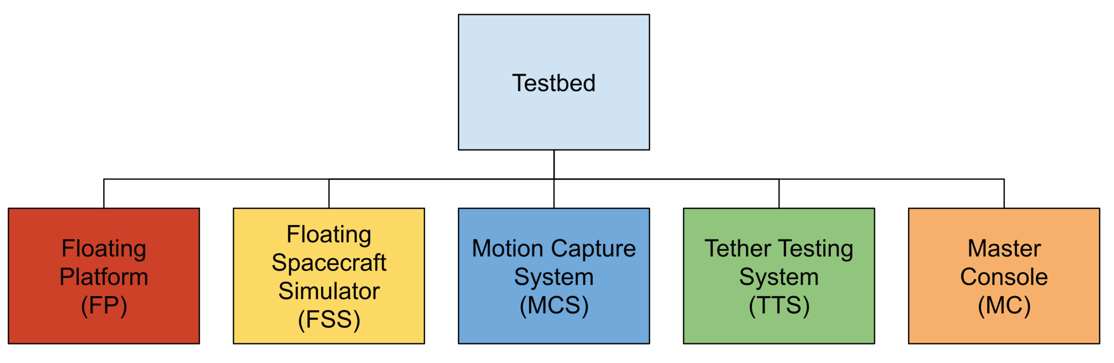
Figure 2.
Laboratory setup. The subsystems of the testbed are framed with the corresponding colours, referenced in Figure 1.
Figure 2.
Laboratory setup. The subsystems of the testbed are framed with the corresponding colours, referenced in Figure 1.
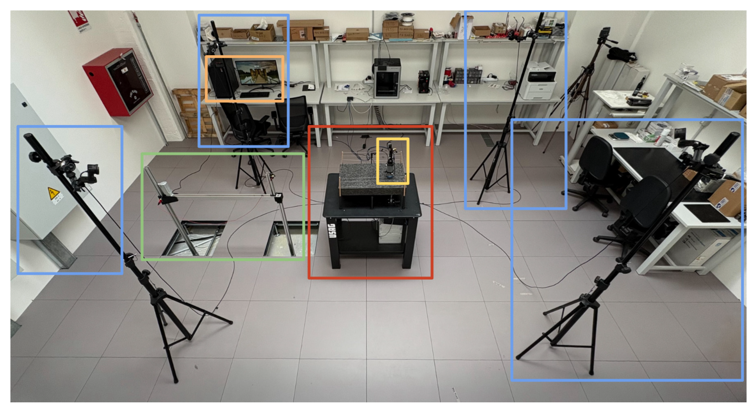
Figure 3.
3(a) 3D model of the FP. 3(b) Physical apparatus of the FP.

Figure 4.
Air tank container with the air-bearing laid on a microfiber cloth, reflective markers (left) and pneumatic system (right).
Figure 4.
Air tank container with the air-bearing laid on a microfiber cloth, reflective markers (left) and pneumatic system (right).
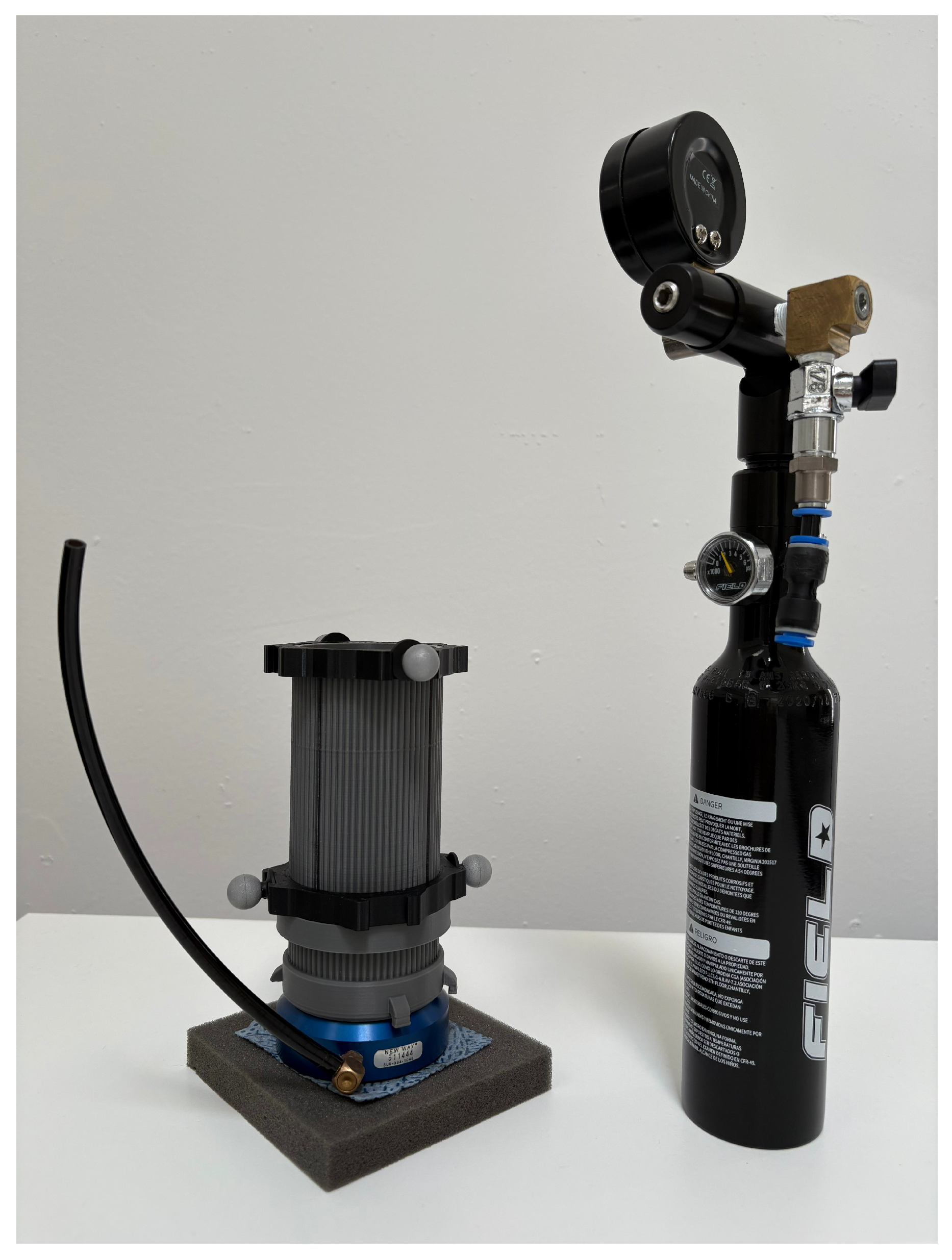
Figure 5.
Detailed schematics of the FSS pneumatic system.
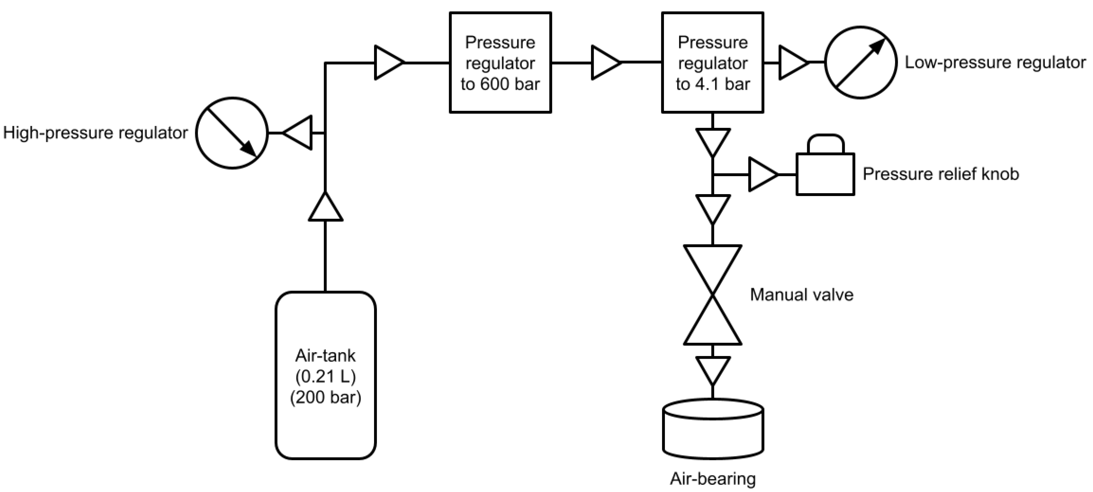
Figure 6.
MCS visualization output, evidencing the FSS (red), the granite table (cyan) and the stainless-steel table (yellow).
Figure 6.
MCS visualization output, evidencing the FSS (red), the granite table (cyan) and the stainless-steel table (yellow).
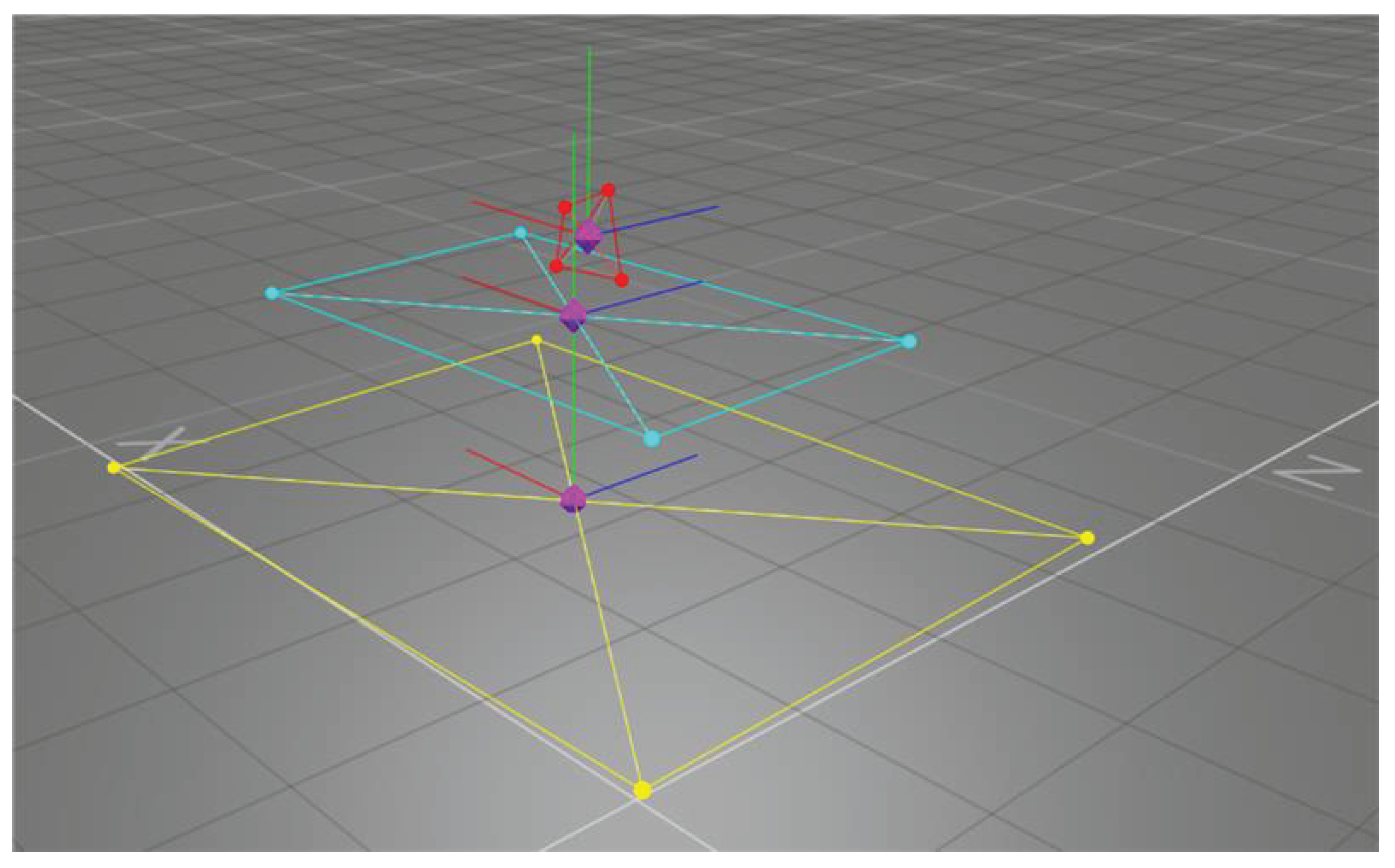
Figure 7.
Illustration of the TTS-deployed (static) architecture.
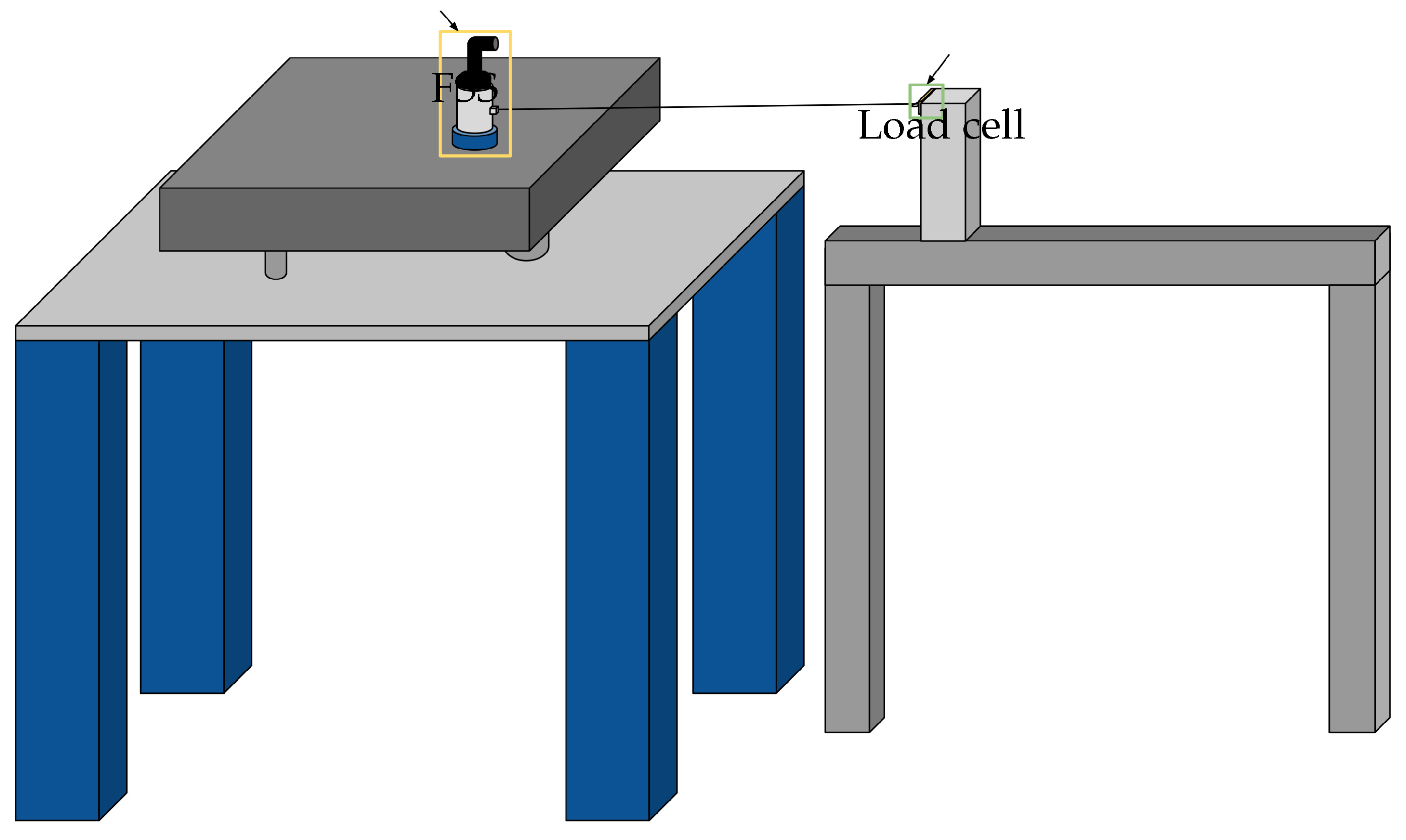
Figure 8.
TTS-deployed (static) architecture.
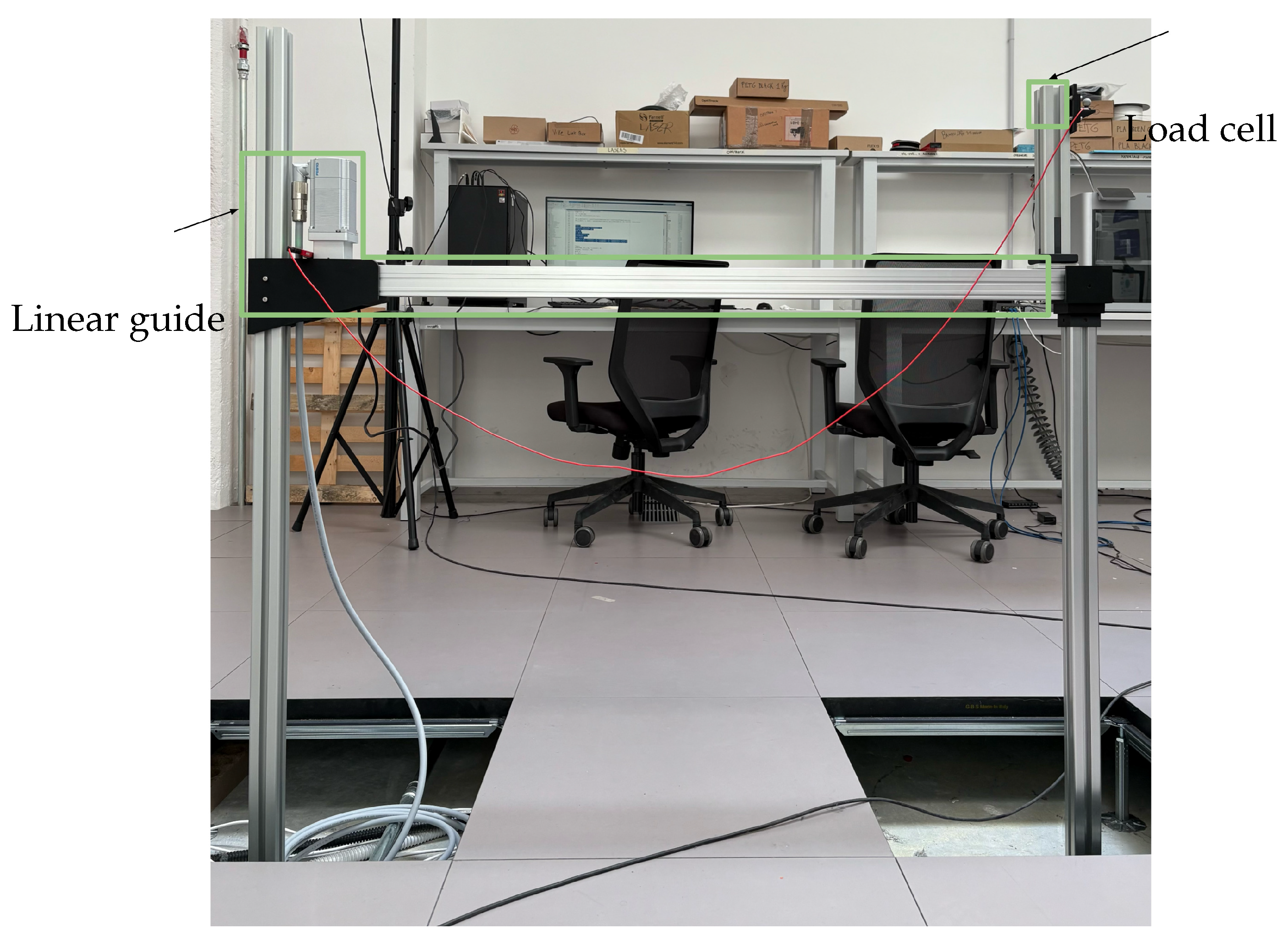
Figure 9.
Illustration of the TTS-deployment (dynamic) architecture.
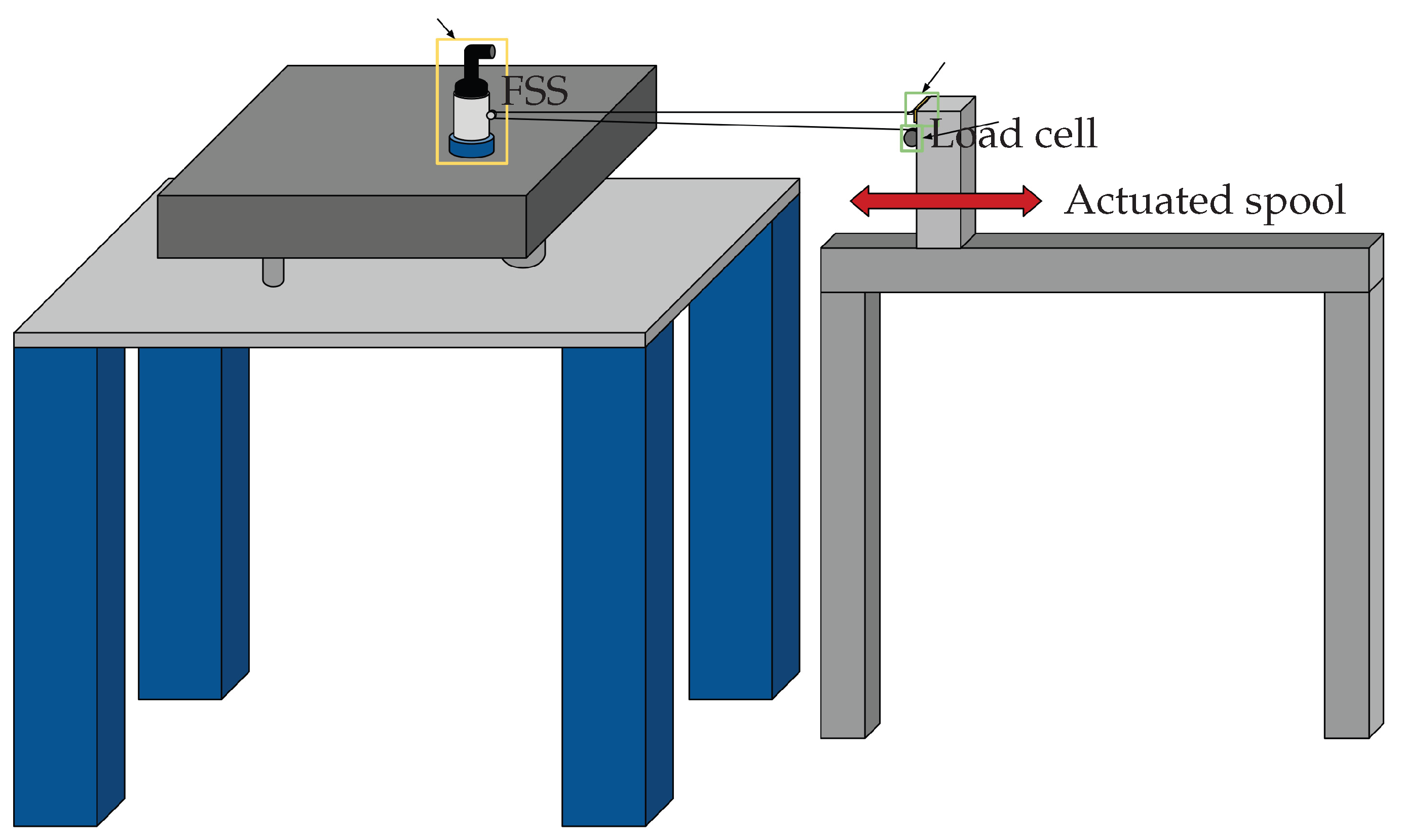
Figure 10.
Local-Vertical Local-Horizontal Cartesian Coordinate System with origin at the Center of Mass of the Target (T).
Figure 10.
Local-Vertical Local-Horizontal Cartesian Coordinate System with origin at the Center of Mass of the Target (T).
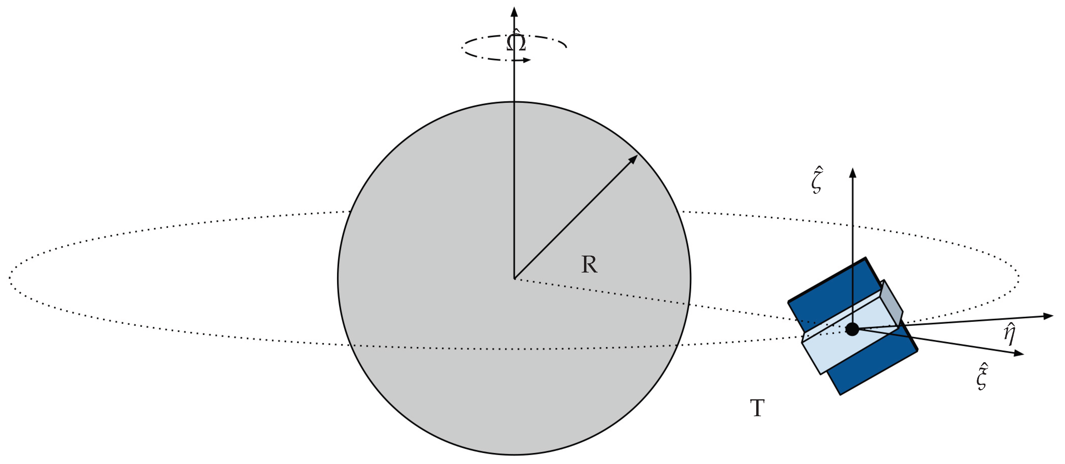
Figure 11.
Granite monolith geometrical characteristics.
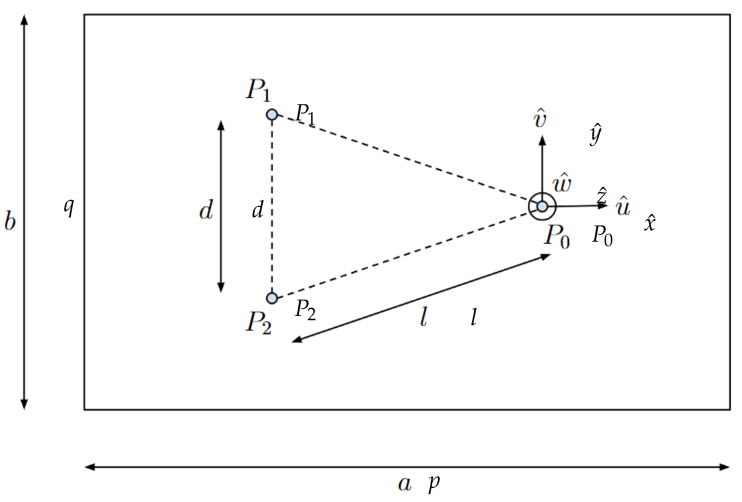
Figure 12.
Schematic view of first linear actuator displacement.
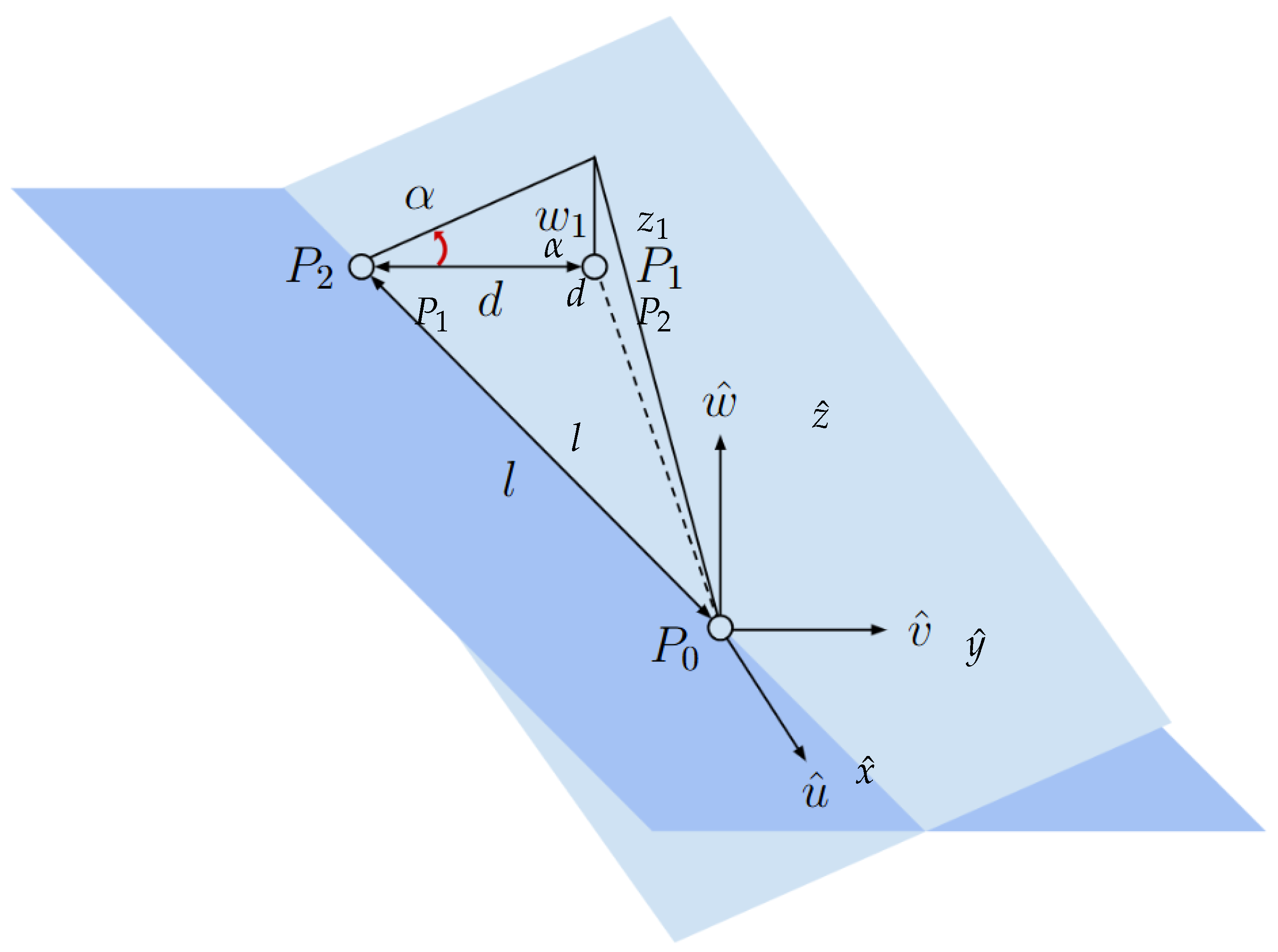
Figure 13.
Schematic view of second linear actuator displacement.
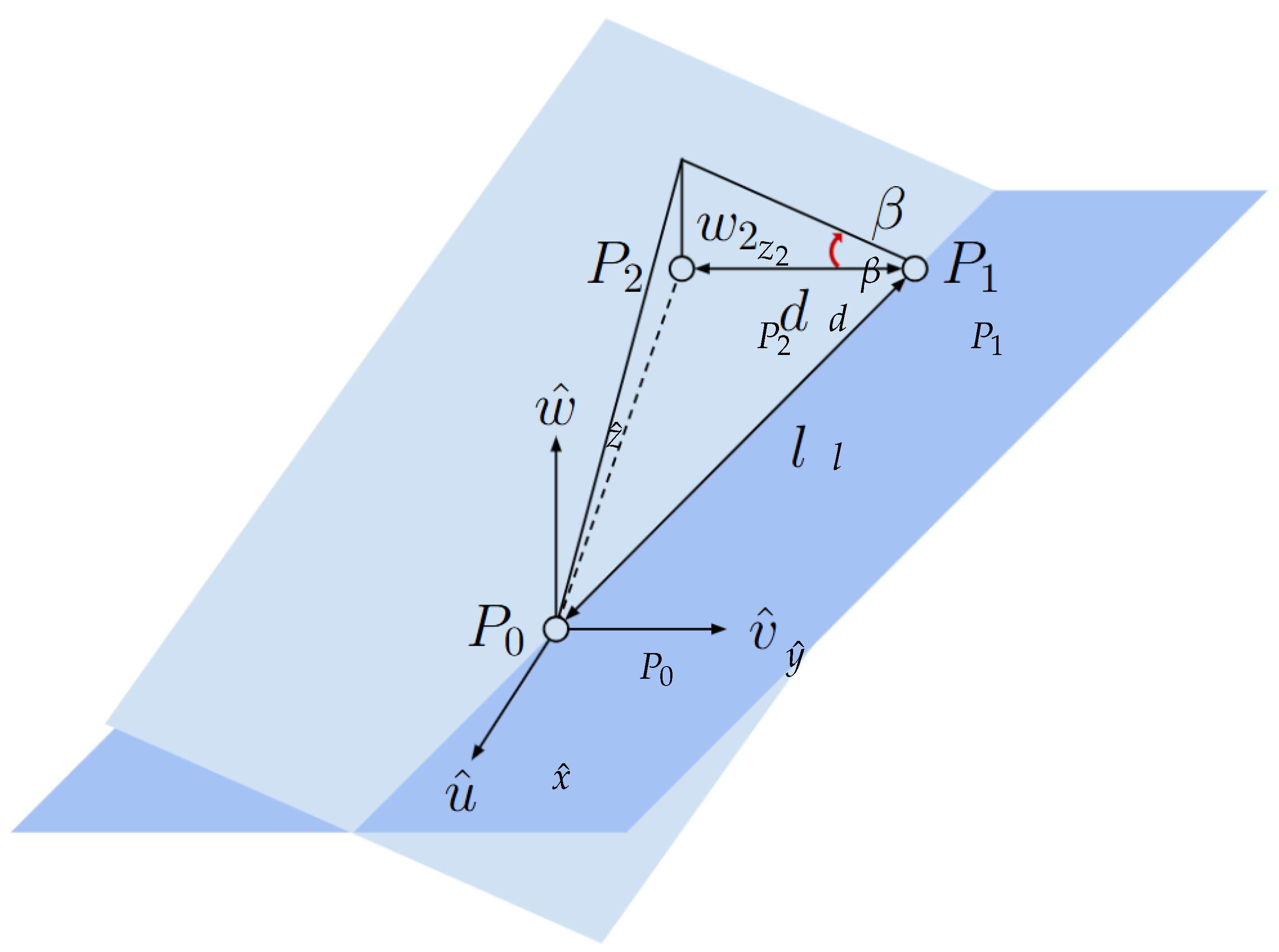
Figure 14.
Map of reproducible acceleration on the monolithic granite table.
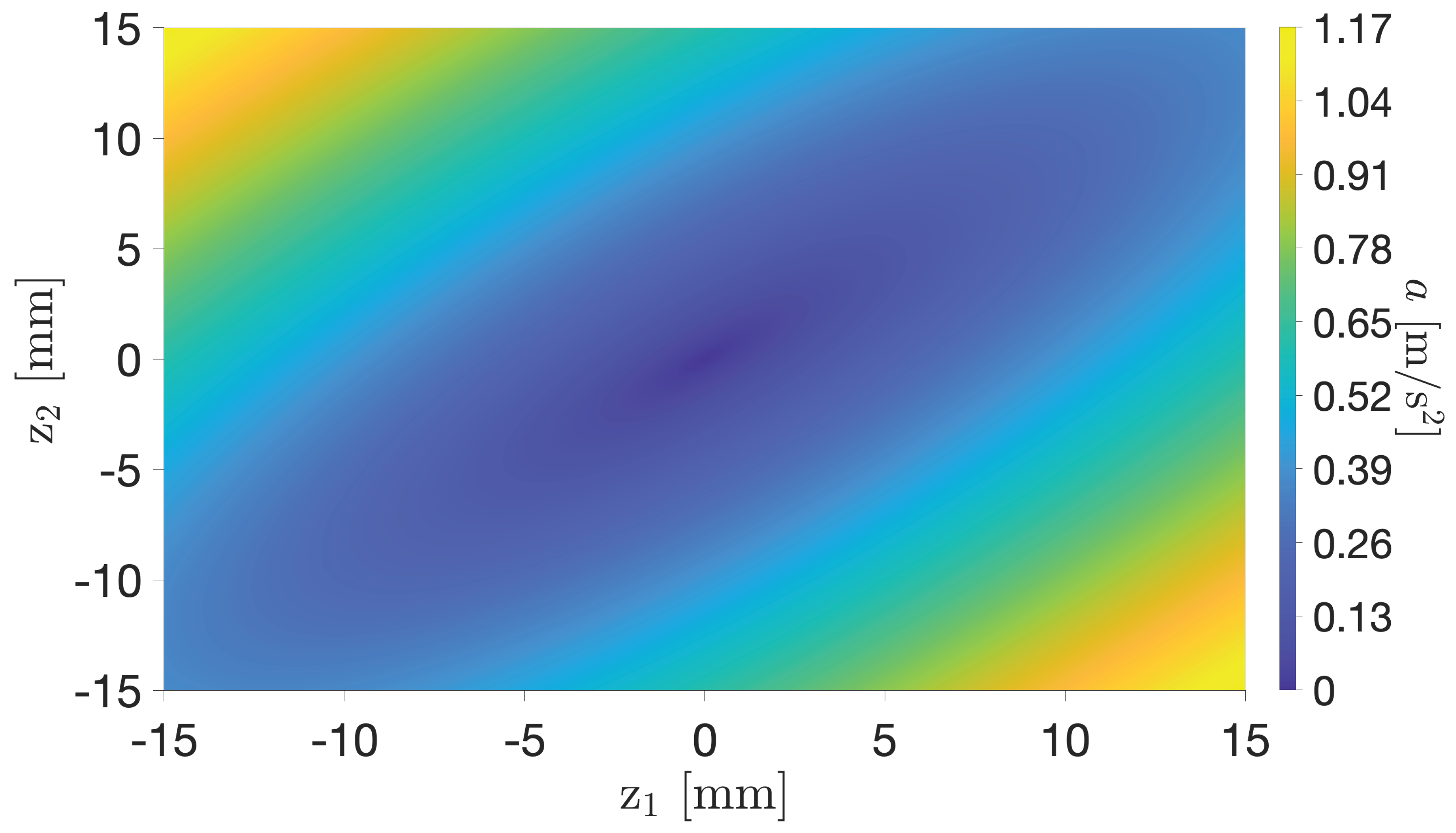
Figure 15.
Flow chart of the closed-loop calibration algorithm.
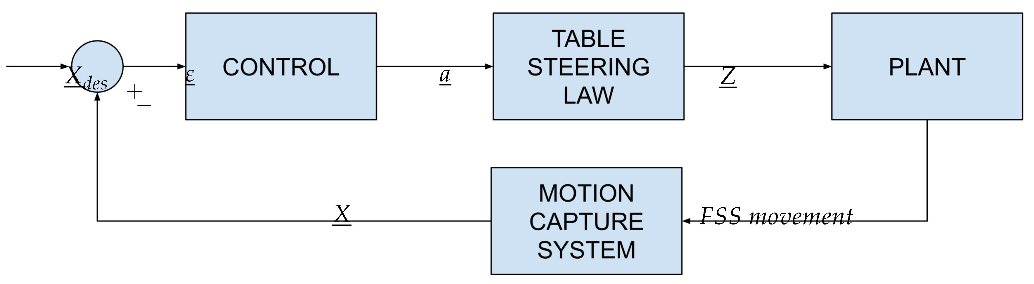
Figure 16.
Flow chart for the HCW emulation test.
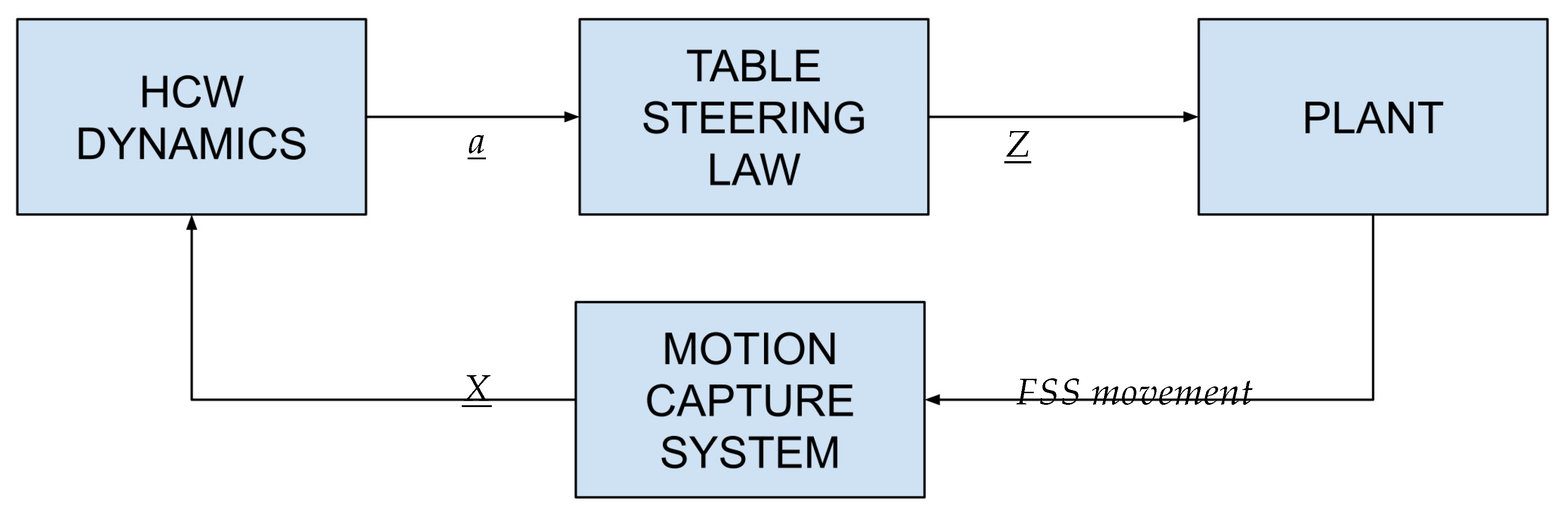
Figure 17.
Illustration of a stabilized TSS in a cross-track configuration.
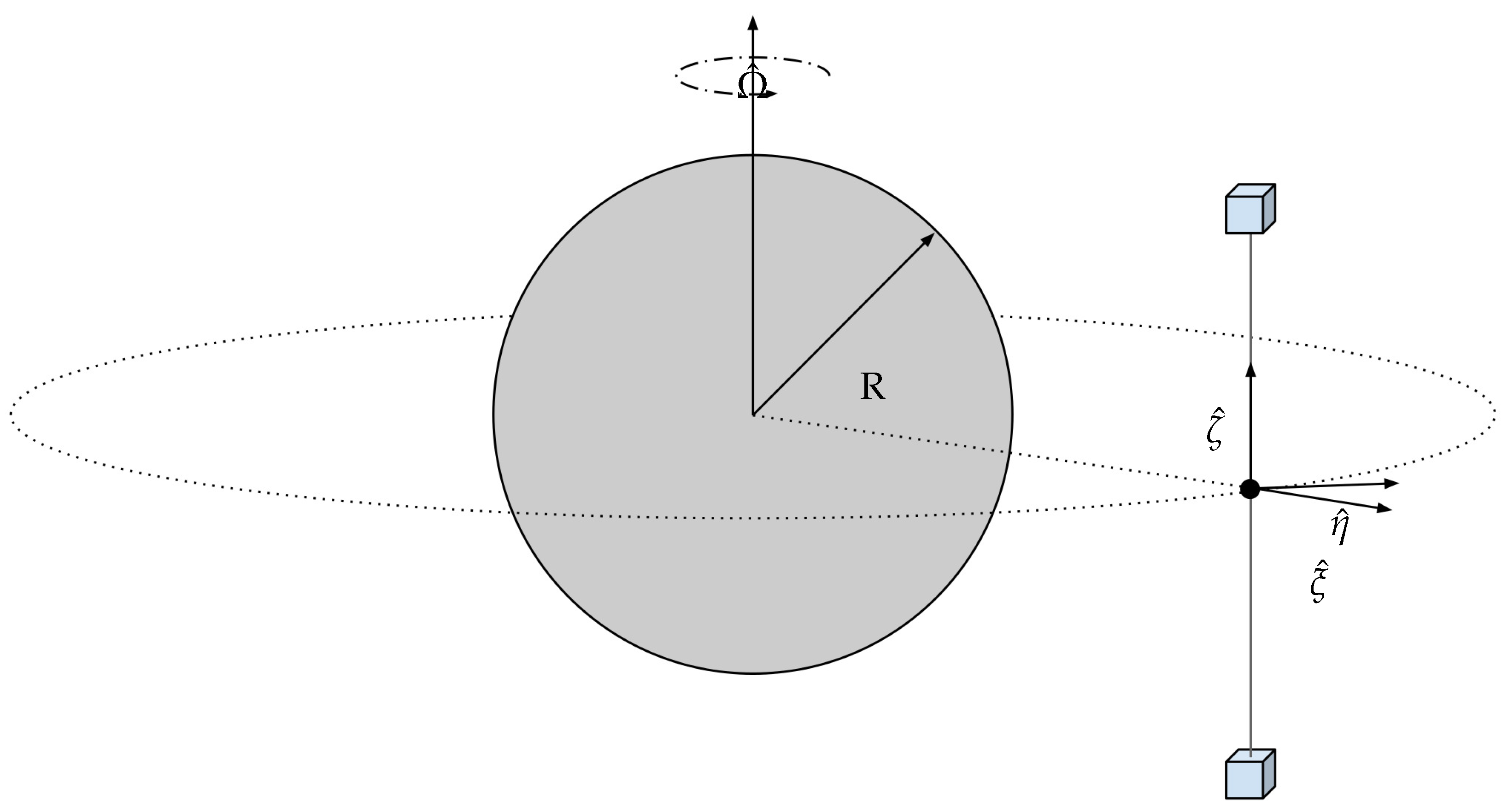
Figure 18.
Time evolution of FSS coordinates over time.
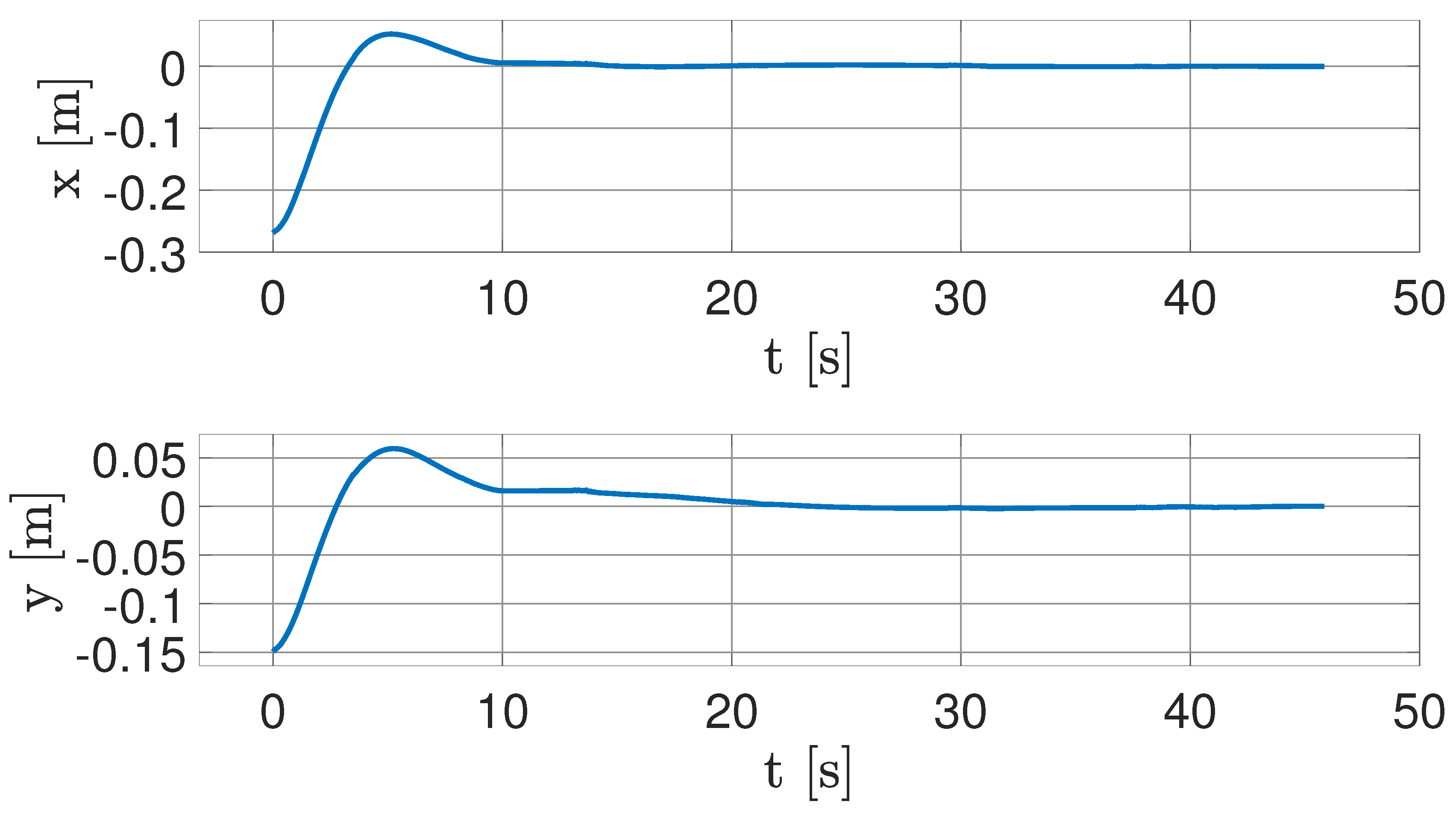
Figure 19.
Real-case trajectory propagated in LVLH CCS.
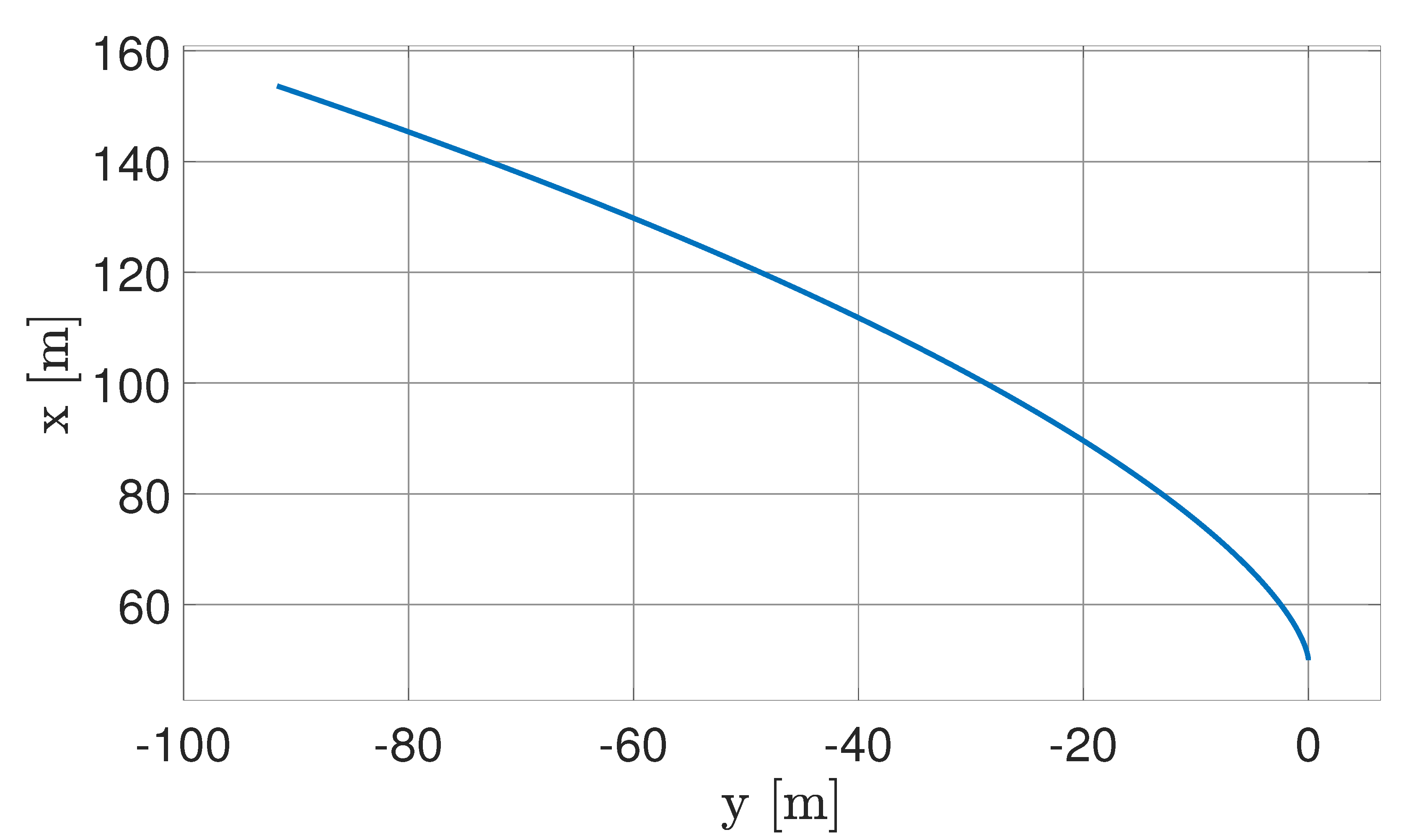
Figure 20.
Real-case acceleration.
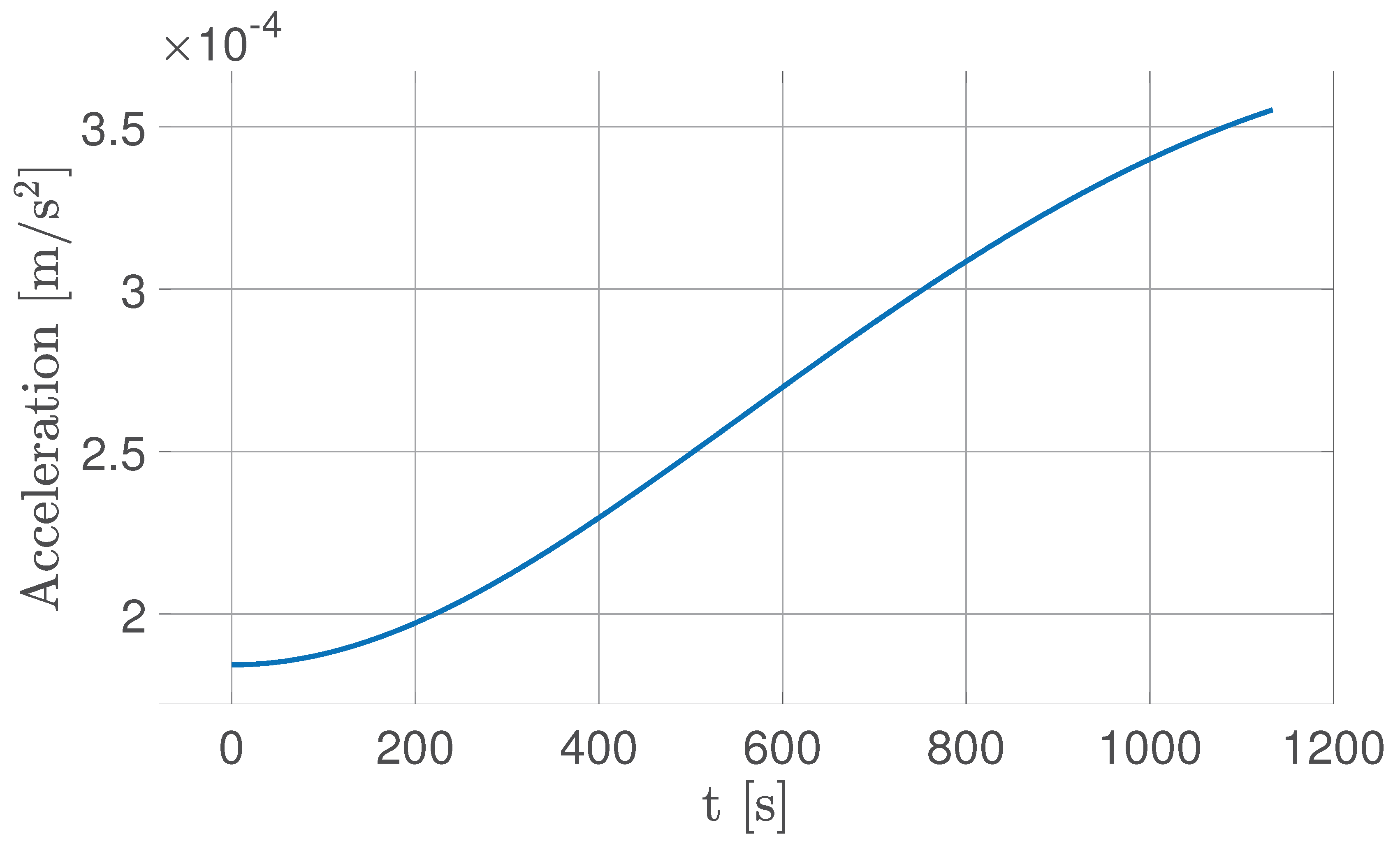
Figure 21.
Comparison between HCW analytical solution and experimental trajectories.
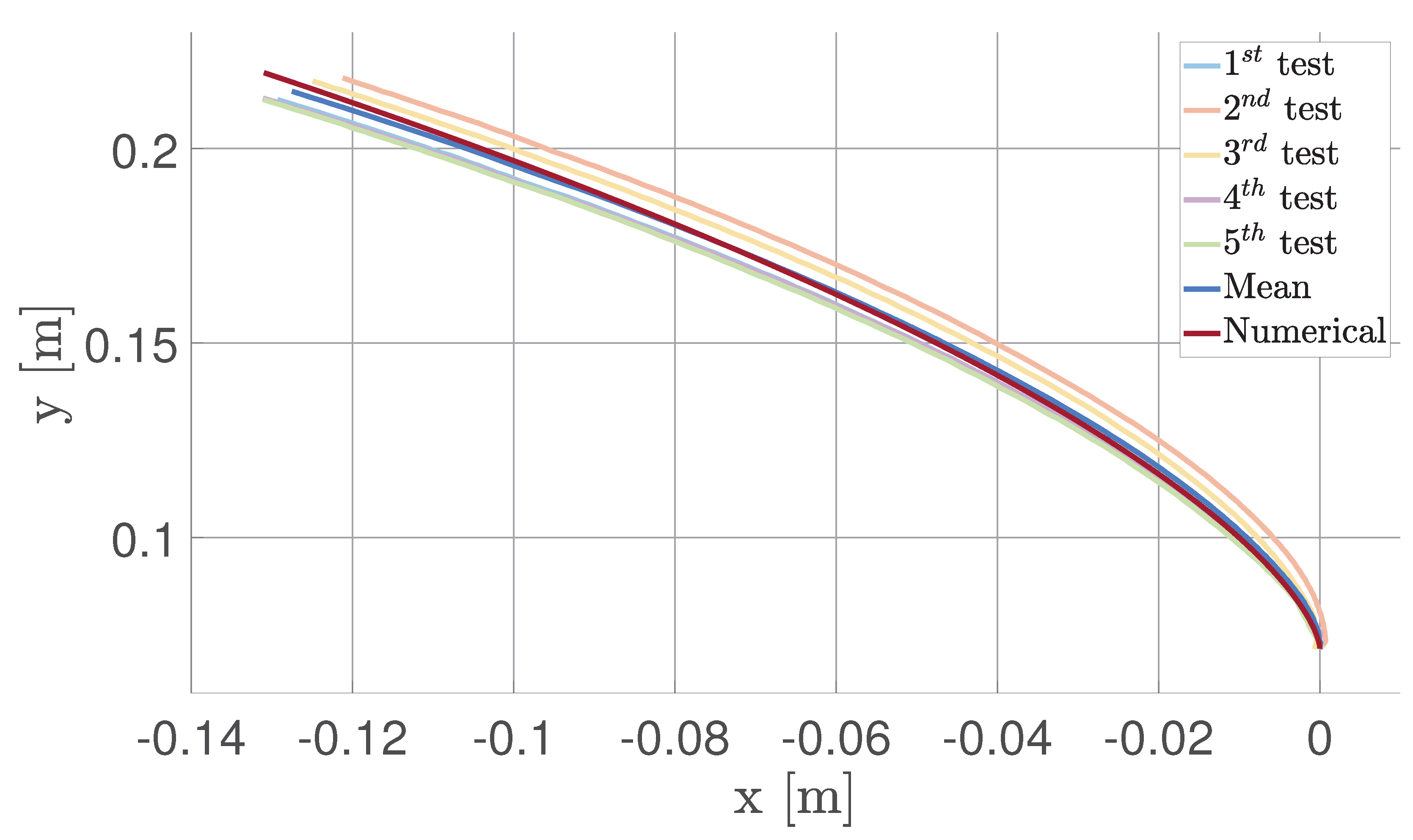
Figure 22.
Absolute error between the numerical and experimental trajectories.
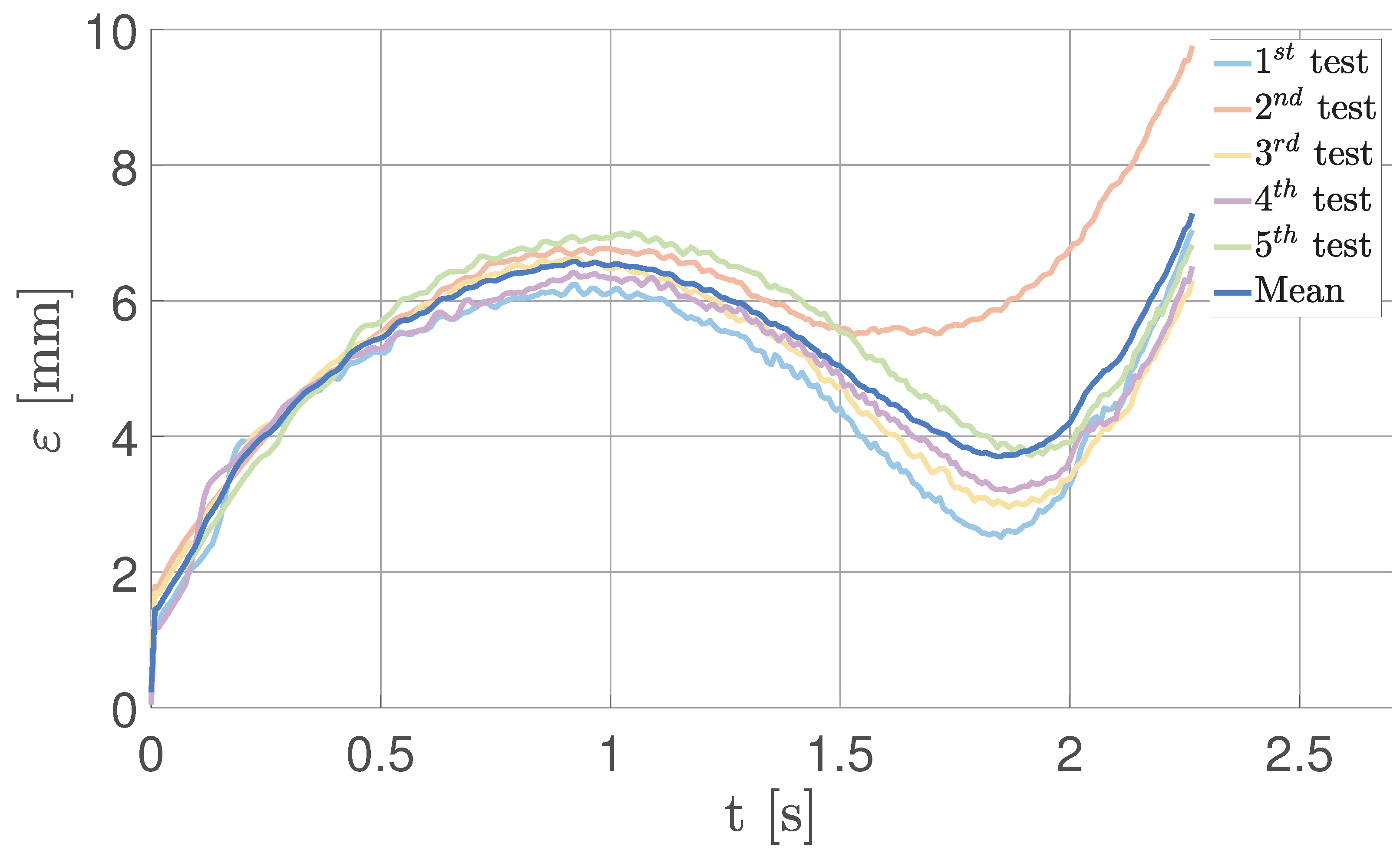
Figure 23.
Real-case acceleration for the cross-track TSS
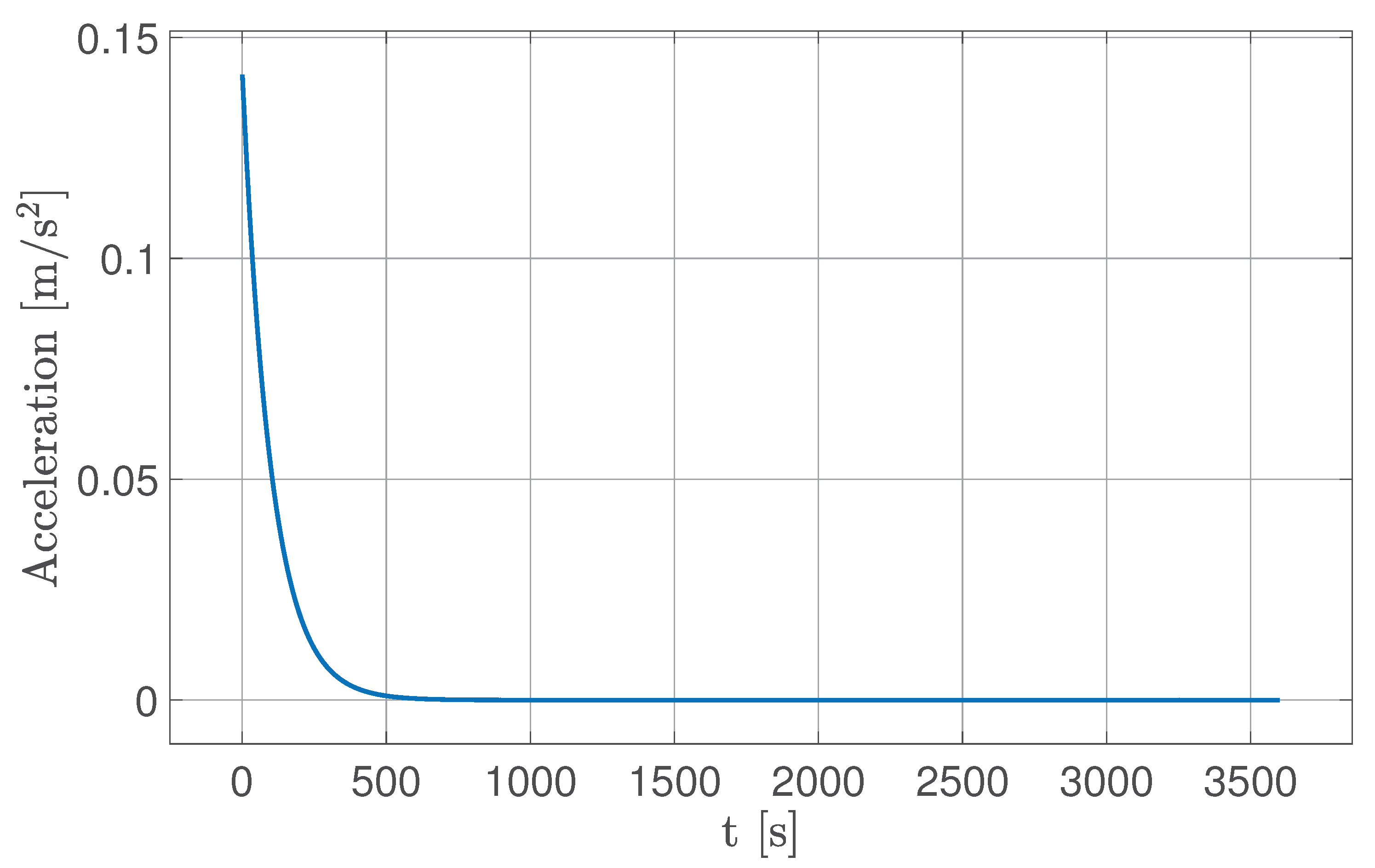
Figure 24.
Time evolution of FSS coordinates under tether tension.
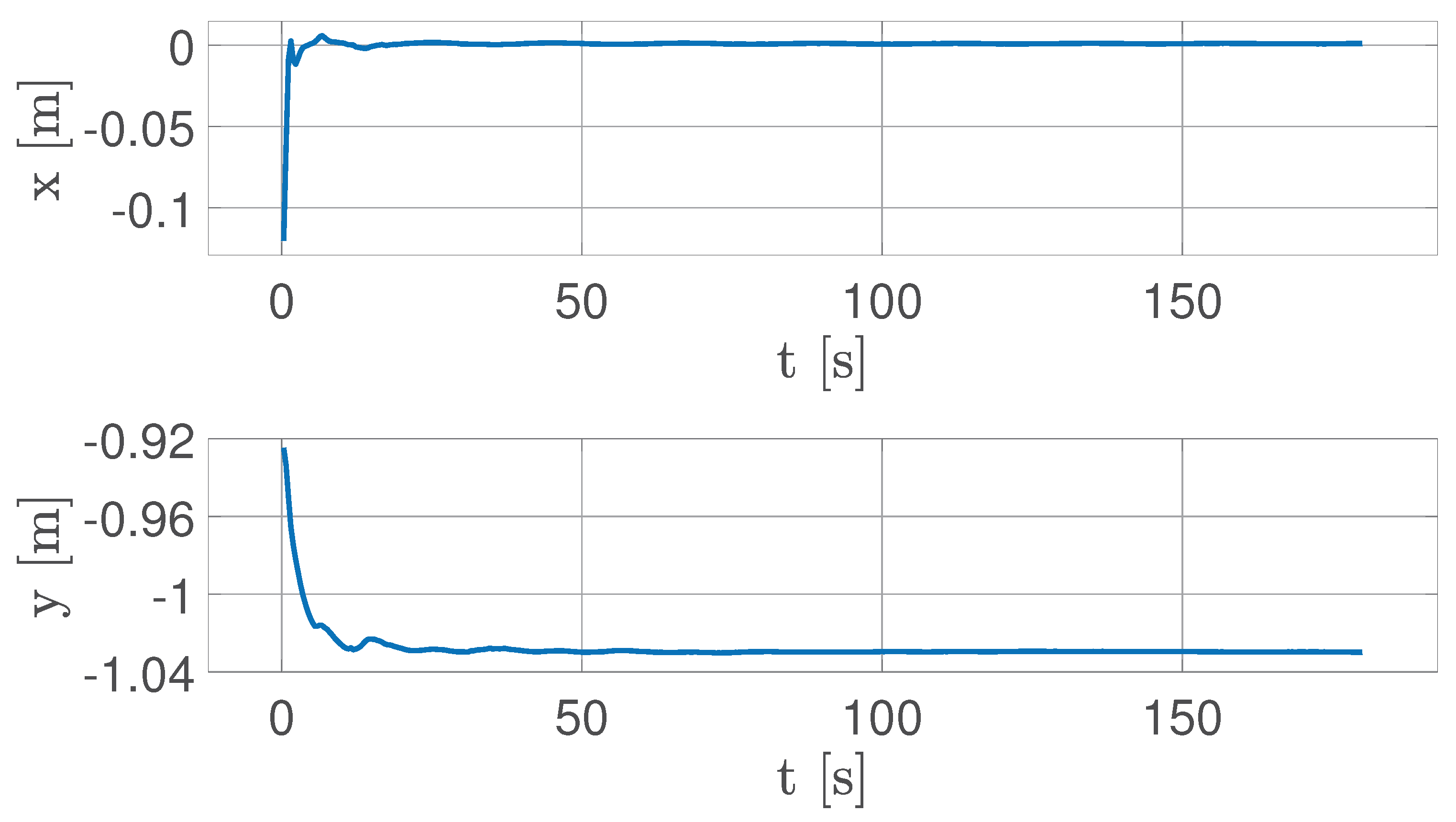
Figure 25.
Tension acting on the FSS (blue) and attitude angle of the FSS (orange)
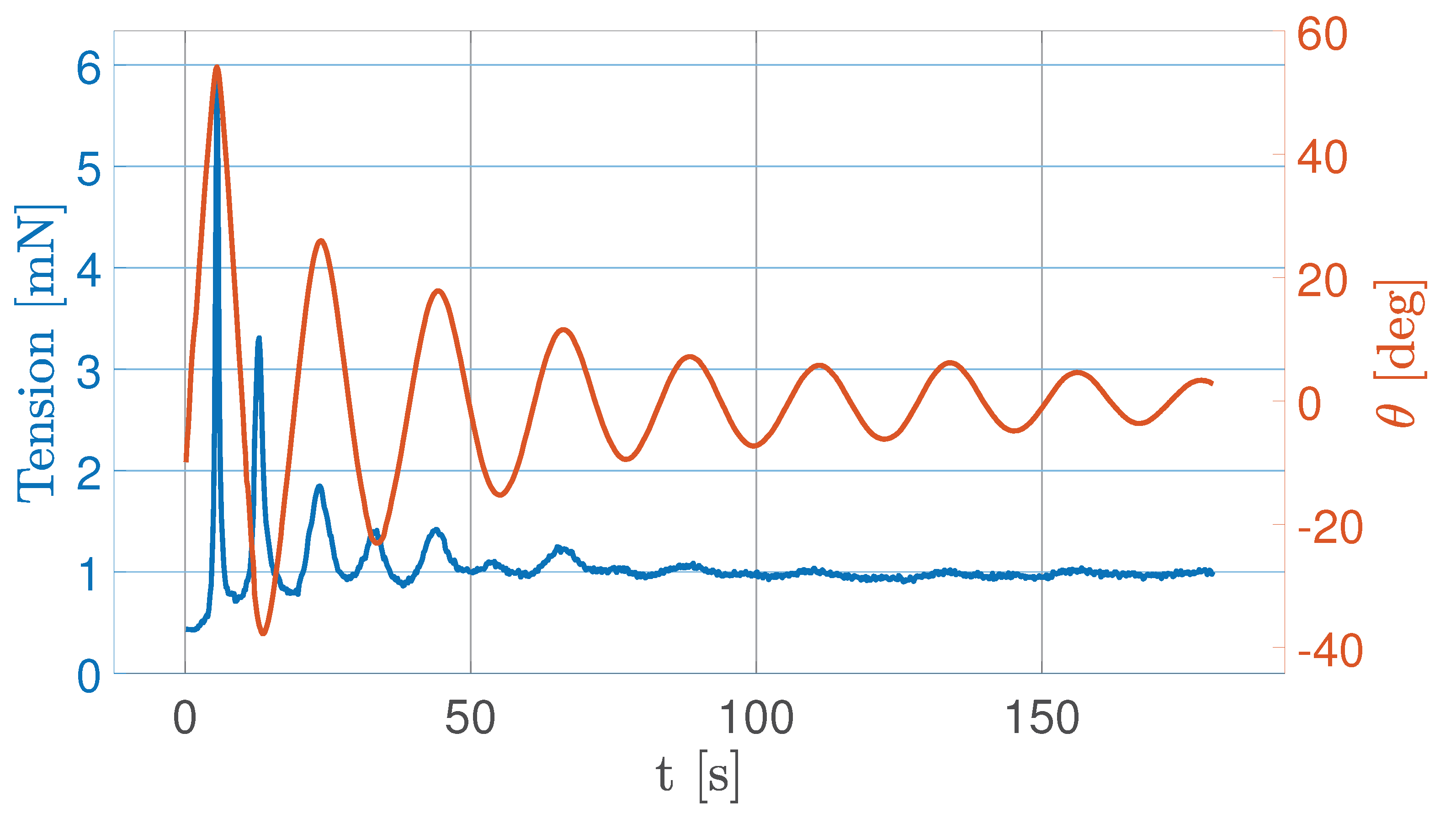

Table 1.
Floating Platform components’ properties.
| GRANITE SLAB | Value | Unit of Measure |
|---|---|---|
| Manufacturer | Zali Precision | |
| Size | 630 × 400 × 80 | [mm × mm × mm] |
| Mass | 60 | [kg] |
| Planarity | 2.5 | [m] |
| ACTUATOR | ||
| Manufacturer | Nanotech | |
| Quantity | 2 | |
| Maximum speed | 30 | [mm/s] |
| Step resolution | 0.01 | [mm/step] |
| Motor holding torque | 1.12 | [Nm] |
| Stroke | 38.1 | [cm] |
| Step angle | 1.8 | [deg] |
| LASER SENSOR | ||
| Manufacturer | Micro-Epsilon | |
| Quantity | 3 | |
| Power voltage | 24 | [V] |
| Power consumption | <2 | [W] |
| Start of Measuring Range SMR | 5 | [cm] |
| End of measuring Range EMR | 15 | [cm] |
| Measuring range MR | 10 | [cm] |
| Weight | 30 | [g] |
| Wavelength | 670 | [nm] |
Table 2.
Characteristics of the MCS.
| MCS | Value | Unit of Measure |
|---|---|---|
| Manufacturer | OptiTrack | |
| Cameras quantity | 4 | |
| Resolution | 1.3 | [Mega Pixel] |
| Latency | 8.3 | [ms] |
| Position accuracy | ± 0.20 | [mm] |
| Attitude accuracy | ± 0.50 | [mm] |
| Frame rate | 120 | [FPS] |
| Cover area | 9 × 9 | [m × m] |
| Tripod height | 215 | [cm] |
Table 3.
Tether subsystem’s properties.
| LOAD CELL | Value | Unit of Measure |
|---|---|---|
| Manufacturer | Futek | |
| Quantity | 1 | |
| Max load | 2 | [mN] |
| Natural frequency | 140 | [Hz] |
| Mass | 0.0193 | [kg] |
| Tether length | 1 | [m] |
Table 4.
Maximum and minimum acceleration reproducible on the matching plane.
| Maximum acceleration | 1.1688 | m/s2 |
|---|---|---|
| Minimum acceleration | 0.0025 | m/s2 |
Disclaimer/Publisher’s Note: The statements, opinions and data contained in all publications are solely those of the individual author(s) and contributor(s) and not of MDPI and/or the editor(s). MDPI and/or the editor(s) disclaim responsibility for any injury to people or property resulting from any ideas, methods, instructions or products referred to in the content. |
© 2025 by the authors. Licensee MDPI, Basel, Switzerland. This article is an open access article distributed under the terms and conditions of the Creative Commons Attribution (CC BY) license (http://creativecommons.org/licenses/by/4.0/).
Copyright: This open access article is published under a Creative Commons CC BY 4.0 license, which permit the free download, distribution, and reuse, provided that the author and preprint are cited in any reuse.


