
Submitted:
28 July 2025
Posted:
29 July 2025
You are already at the latest version
Abstract
In 2016, Kumamoto was struck by two earthquakes. My condominium was destroyed, so we decided to search locally for a new section to build a home. The place we chose was a rich in groundwater so we thought to use it and so contributed to our hometown. The first floor would be an example of disaster relief architecture by using it as a public bath, and would provide water in times of disaster. The second floor would be our private home with no bath, we would use the public bath as ours. This report describes our construction process during which first floor ceiling was assembled using superimposed openwork beams of thinned wood. We designed the damaged structure to bear any subsequent earthquake. Since the remaining seismic capacity of a couple of nearby RC buildings dropped to about 60%, the analytical model for subsequent earthquakes assumed a reduced bearing capacity and an effective structural frame. The roof was designed using CLT arches. The joints have close fitting butterfly-shaped timber connectors without metal. Connector bending tests were performed. After the earthquake, construction costs skyrocketed. To reduce costs we took charge of site supervision, carpentry, and became the public bath operator. All this as a direct result of strong feelings for my hometown.
Keywords:
timber fitting connector
; CLT
; superimposed openwork beam
; thinned wood
; high strength timber shear wall
; timber frame structure
; multiple earthquakes
; disaster reconstruction
; recovery utilizing a public bath
; community preparedness
1. Introduction
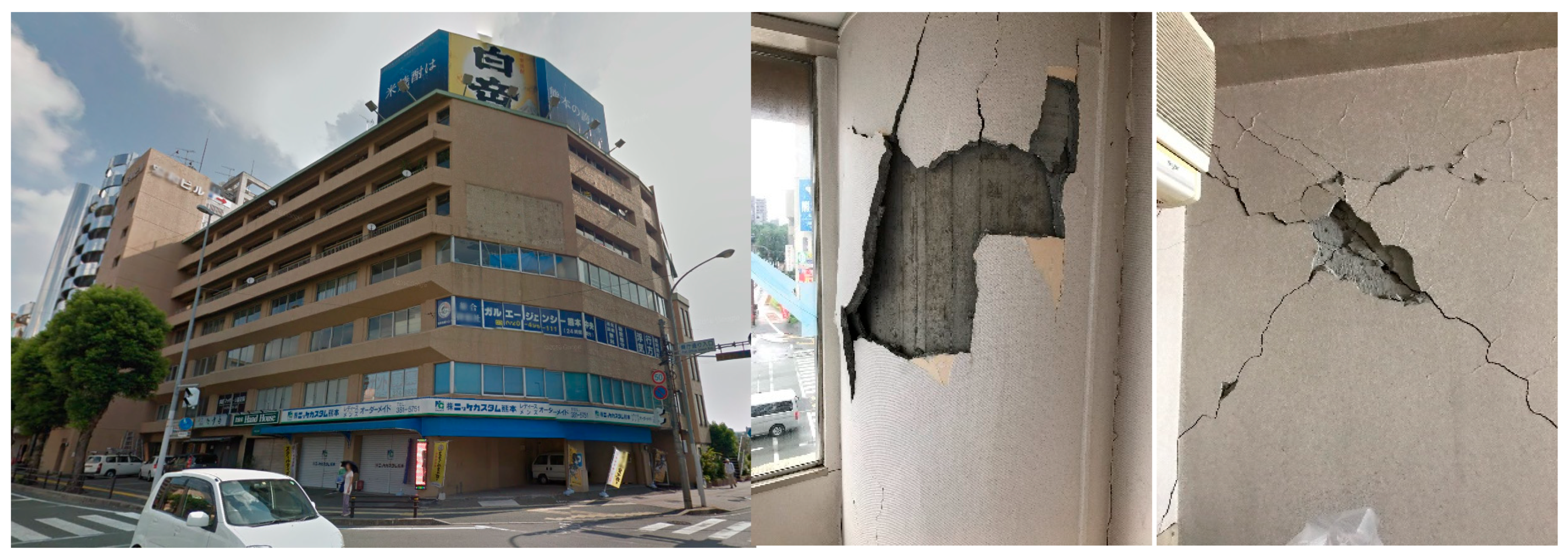
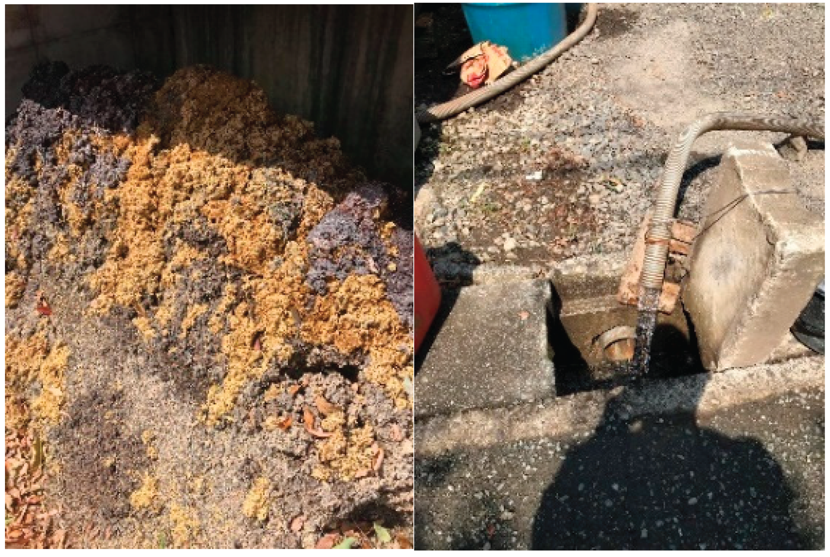
In recent years, environmental issues have become a global concern, and natural disasters are occurring with increasing frequency amid the risk of resource depletion caused by excessive human consumption. Japan’s southwestern region, particularly Kumamoto Prefecture, sits at the nexus of several converging tectonic plates and is therefore highly susceptible to seismic events. In April 2016, a sequence of Mw >7.0 earthquakes struck the area, causing extensive damage to the infrastructure and leaving many architectures, including our condominium, in partial or total ruin (Figure 1). Beyond the structural failures, prolonged disruptions to lifeline services—most notably a multi-month interruption of the municipal water supply—compounded hardships for residents forced to rely on overcrowded public bathhouses, where insufficient capacity and clogged drainage amplified health and hygiene concerns (Figure 2). Immediately after the shocks, I temporarily suspended my structural design practice to assist with building recovery, volunteering primarily in debris clearance. Concurrently, at the prefecture’s request, I performed rapid safety screenings and affixed color-coded danger-level stickers to compromised structures (Figure 3). I then conducted detailed damage-classification surveys to assess necessary seismic retrofitting. These assessments informed seismic diagnoses in which the bearing capacity of affected structural elements was systematically reduced. Our condominium was ultimately classified as “large-scale half-collapse,” necessitating full rebuilding. As I watched my hometown become increasingly dotted with vacant lots and lose its vitality, my affection for the community compelled me to lead its reconstruction. Amid a marked loss of neighborhood vitality after the quake, our family set out to rebuild not just a home but a valuable community asset. We purchased a nearby parcel blessed with abundant groundwater and conceived a hybrid architecture for both private and public use. Recognizing that effective recovery and reconstruction demand substantial physical resilience—and that hygienic bathing is essential both to restore strength and to promote wellbeing and positive affect—we integrated a public bathhouse on the ground floor. This facility is capable of supplying potable water and bathing services during future emergencies, while the upper level functions as our private residence.
2. Structural Design
The building is a two-story, post-and-beam timber structure. Since the ground floor functions as a public bath, reinforced-concrete shear walls were raised to a height sufficient to prevent buckling under lateral loads. The ground floor ceiling incorporates superimposed, open-work beams milled from thinned domestic timber to enhance rigidity and strength. The entire framework was engineered to sustain subsequent seismic events, even if partially damaged. The roof consists of CLT arches, forming an arched ceiling that enables a loft level.
While municipalities currently designate “wide-area evacuation sites” (e.g., gymnasia) to shelter large numbers of evacuees, the 2016 Kumamoto earthquakes showed that a single, centralized refuge can fail—several gymnasium ceilings collapsed, rendering those sites unusable. Rather than relying exclusively on one major hub, we propose a networked disaster-prevention city model in which private buildings share a variety of relief functions. In this distributed system, individual homes and facilities can serve as nodes offering public baths, community dining halls, temporary lodging, laundry and clothing services, decentralized power generation, and other essential services. Even small-scale nodes—such as our bath-and-home hybrid—can collectively form a resilient, multifaceted network of support across the neighborhood (Figure 4).
2.1. Timber Frame with Superimposed Openwork Beams
The ground-floor public bath is a small-scale space, so we set an approximately 5.0 m ceiling height to create a more open bathing environment. In the post-Kumamoto market—where subcontractor premiums and material costs soared—we adopted a low-cost approach using ungraded Japanese cedar members (90 × 90 mm, 4.0 m long), which cost roughly one-third per cubic meter of engineered wood (E120-F330, 4.0 m). Columns are 105 × 105 mm cedar, with mid-height beams installed in both directions to prevent buckling. Because bathers naturally look upward for extended periods, the ceiling comprises superimposed triangular open-work beams. These overlapped members enhance structural rigidity and flexural capacity. Long screws connect the small square timbers, while the upper and lower flanges of the main girders—and the continuous perimeter columns—are engineered wood. Connections employ long screws (PS8-320) to resist shear forces and long screws (PX8-290) to provide tensile capacity at flange-to-column interfaces (Figure 5). Each girder is split into two branches to boost bending strength within a minimal beam depth, and end-grain joints are reinforced with structural adhesive as a fail-safe.
Figure 5.
Girder–column connection detail.
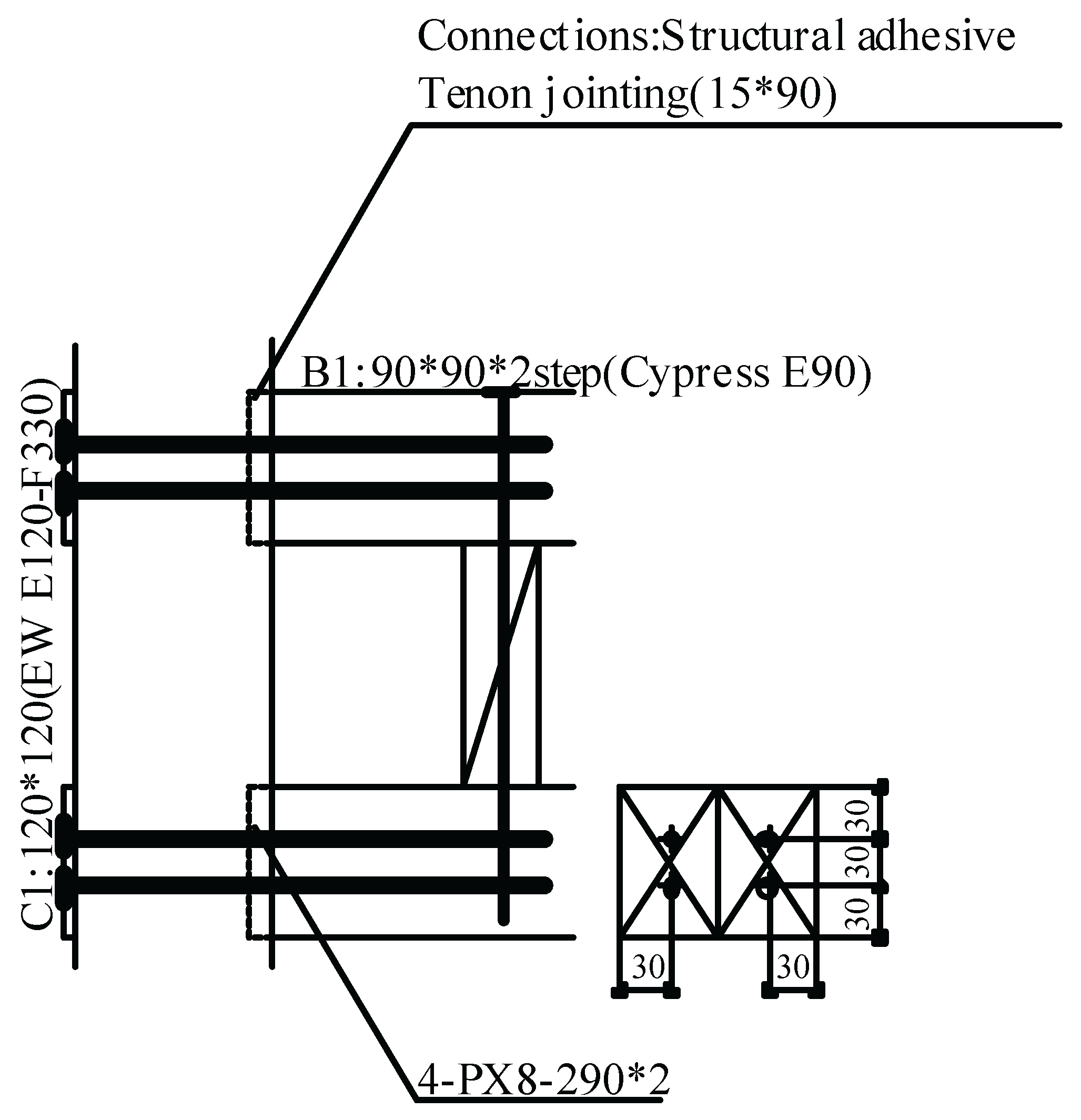
Figure 6.
Erection of superimposed open-work girders (Authors).
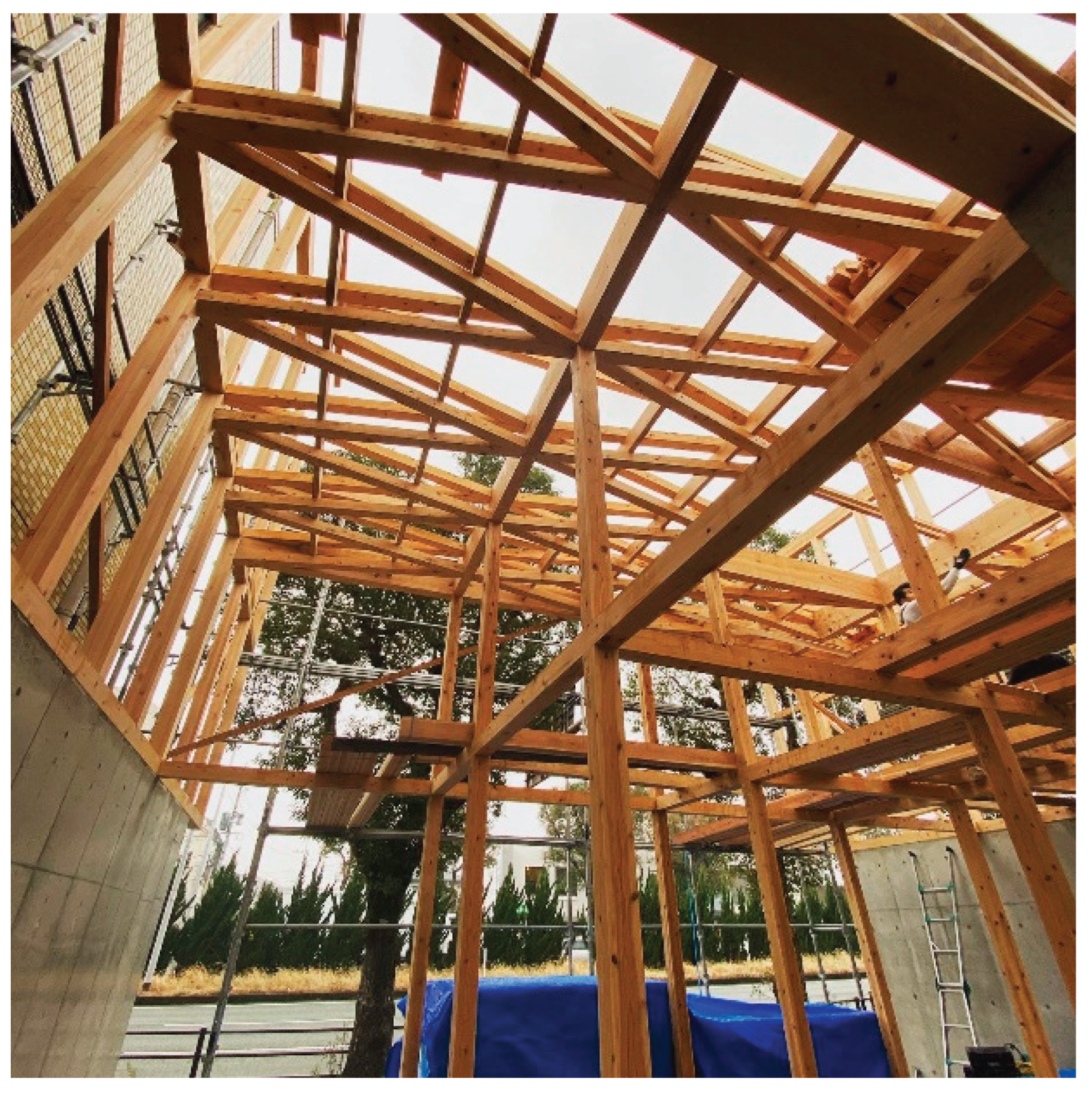
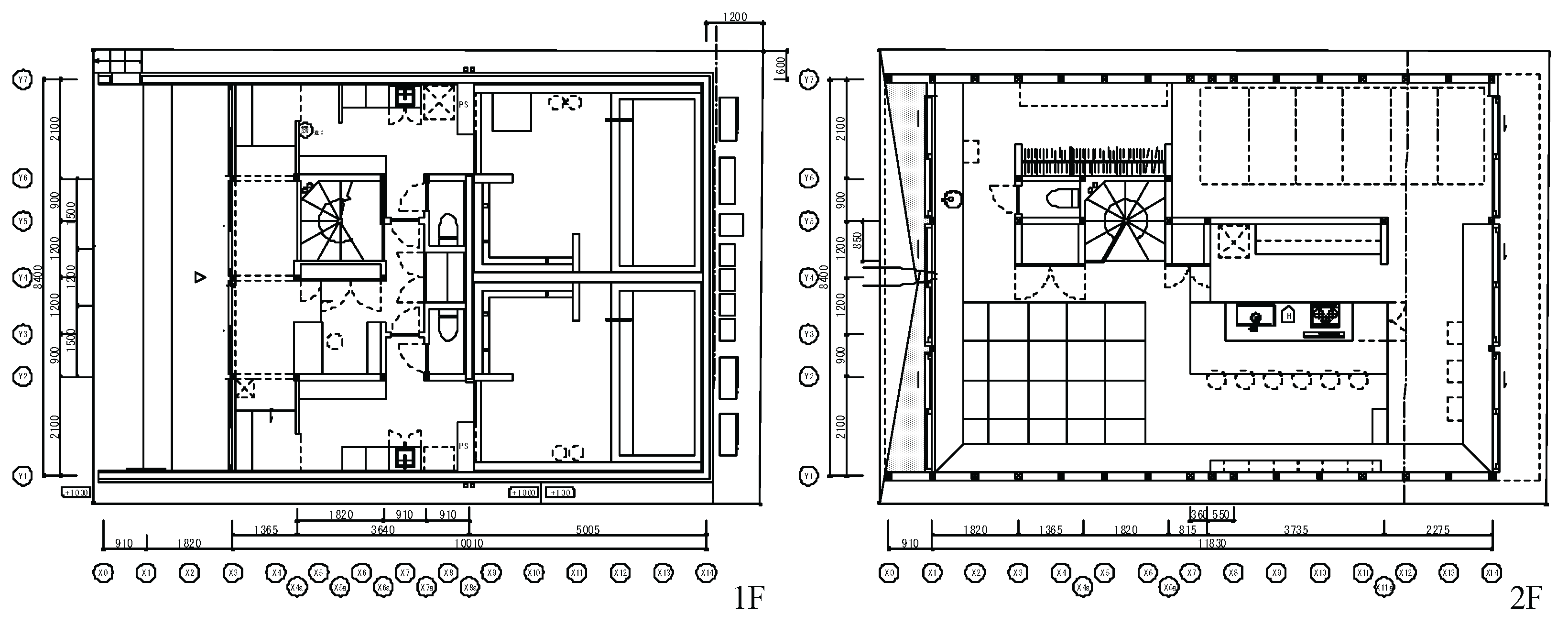
Figure 7.
Floor plan.
2.2. Structural Design Under Consecutive Earthquakes
Addressing demands, we first installed high-strength shear walls (19.6 kN/m) in accordance with the Building Standard Law. As added strengthening and redundancy, the timber ramen frame carries loads from succeeding earthquakes. Seismic loads matching the horizontal forces of the 2016 Kumamoto earthquakes were applied twice in our analysis.
I conducted damage-classification assessments—estimating remaining strength from settlement, tilt, and structural damage—on multiple RC condominiums, the Kumamoto Prefectural Civil Engineering Office, and the Prefectural Government Office. Based on this statistical evaluation, shear walls were assumed to retain only 60 % of their original strength. R is the residual seismic strength ratio, defined as the ratio of remaining bearing performance after damage. For the initial earthquake, the structure was designed using the allowable-stress design method; for the subsequent shock, we applied the same R = 60 % reduction and evaluated the residual ultimate lateral strength under the new loading. The composite moment frame hinges at the top of the shear wall (inflection point), combining the lower wall’s out-of-plane strength with the upper timber ramen system. Connections between shear walls and timber columns, as well as mid-story beams, are pinned (Figure 8). Although the triangular beam enhances horizontal strength, we provided horizontal load capacity solely with 24 mm structural plywood to simplify design assumptions.

Table 1.
Ultimate Lateral Strength After the Disaster.
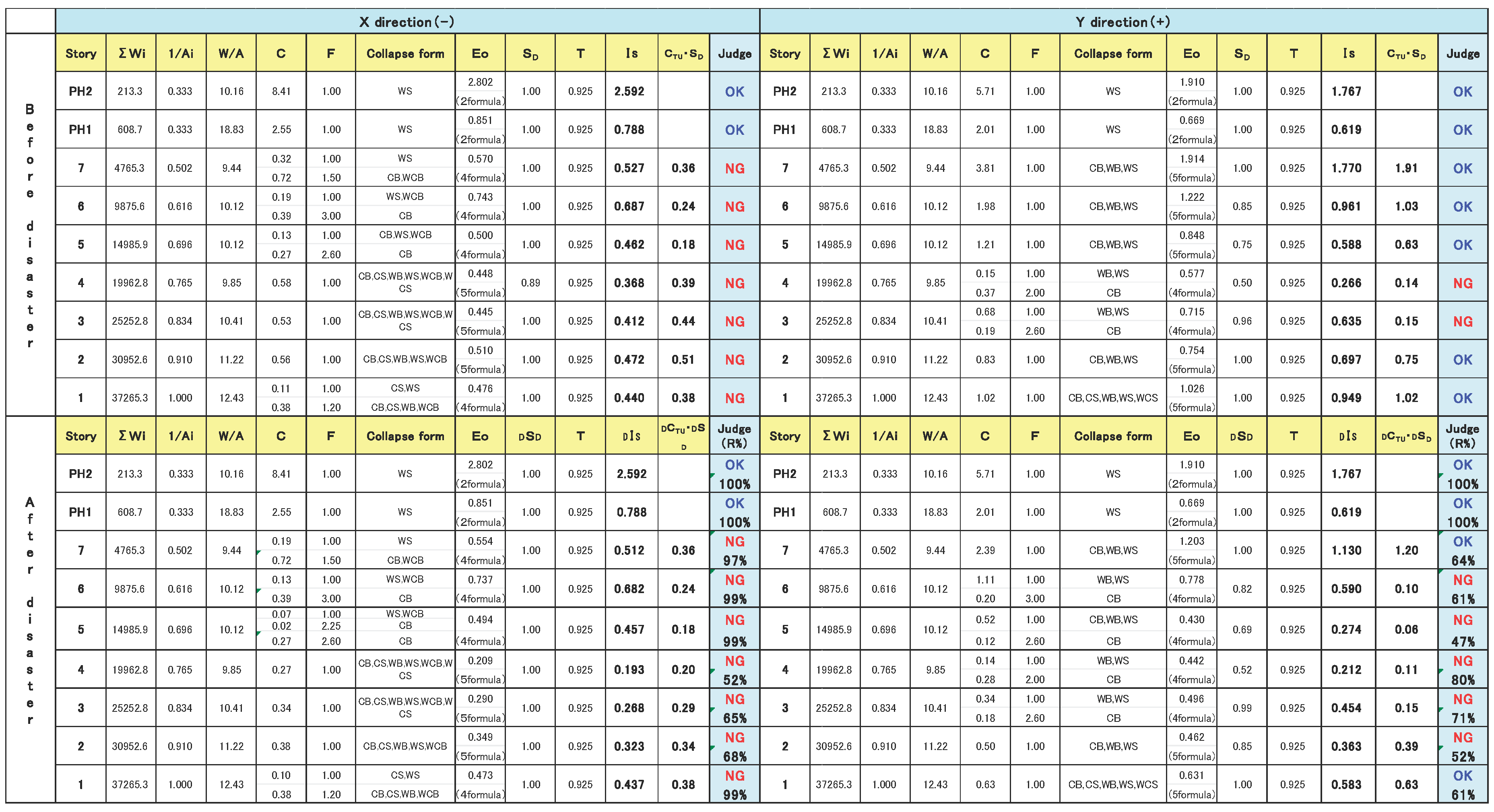 |
Figure 8.
Analysis model under consecutive seismic loading.
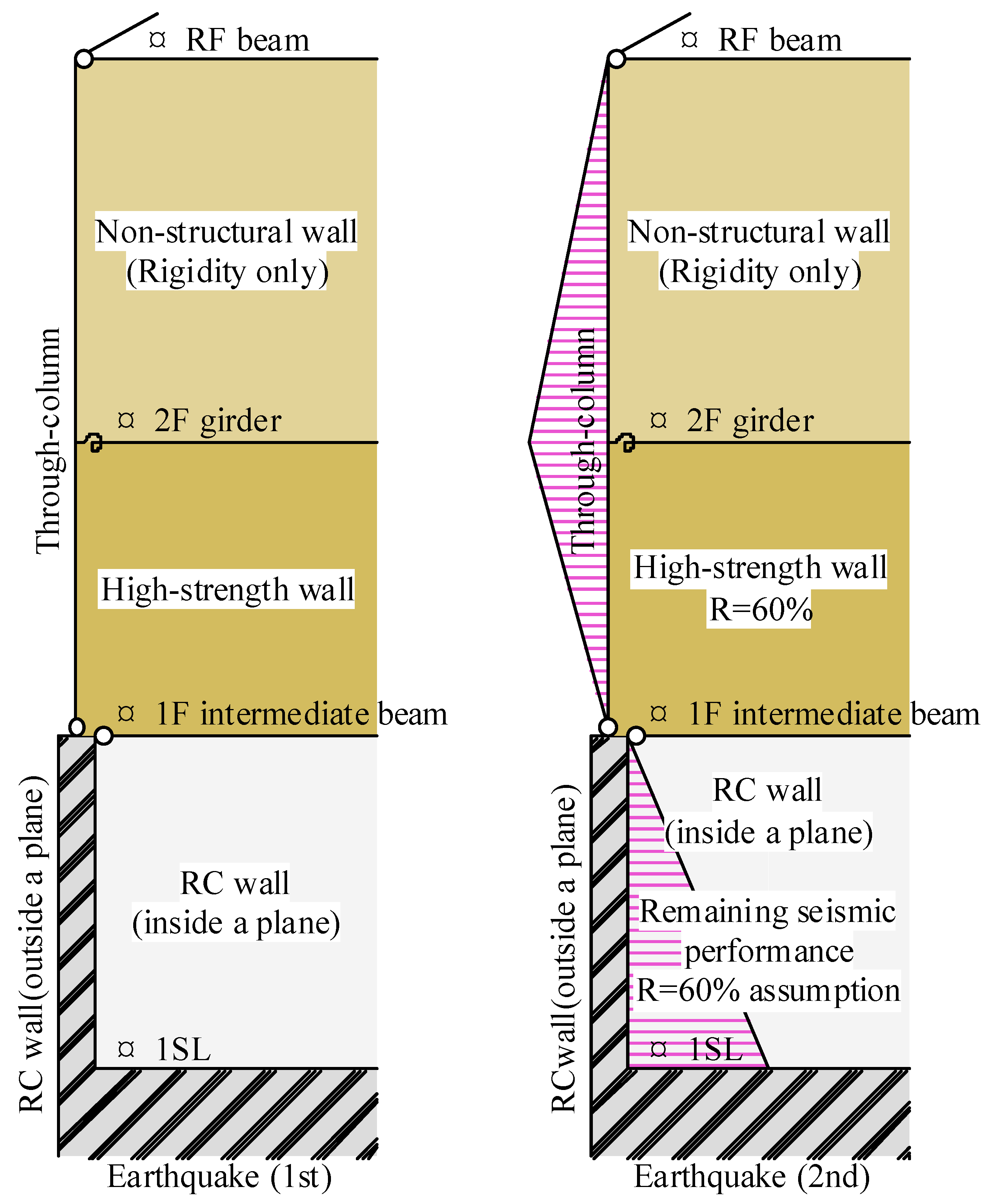
Figure 9.
Shear-Failure Cracks in a Reinforced-Concrete Shear Wall (Authors).
2.3. CLT-Connected Arch with Timber Fitting Connectors
The roof incorporates a loft level by arranging CLT panels into an arch form (Figure 10). Engineered-wood tie beams resist sustained thrust forces. CLT segments carry compressive forces under moderate earthquakes and are subjected to tensile forces during major earthquakes. To accommodate these tension demands, butterfly-shaped, close-fitting timber connectors were used (Figure 11). To reduce costs, temporary supports were omitted during assembly; arched CLT modules were prefabricated at the factory and lifted into place by crane and manual labor. All connections use only these timber connectors—no metal fasteners are present. Because the arches were cantilevered during assembly, connector bending tests were conducted to verify performance (Figure 12 and Figure 13).
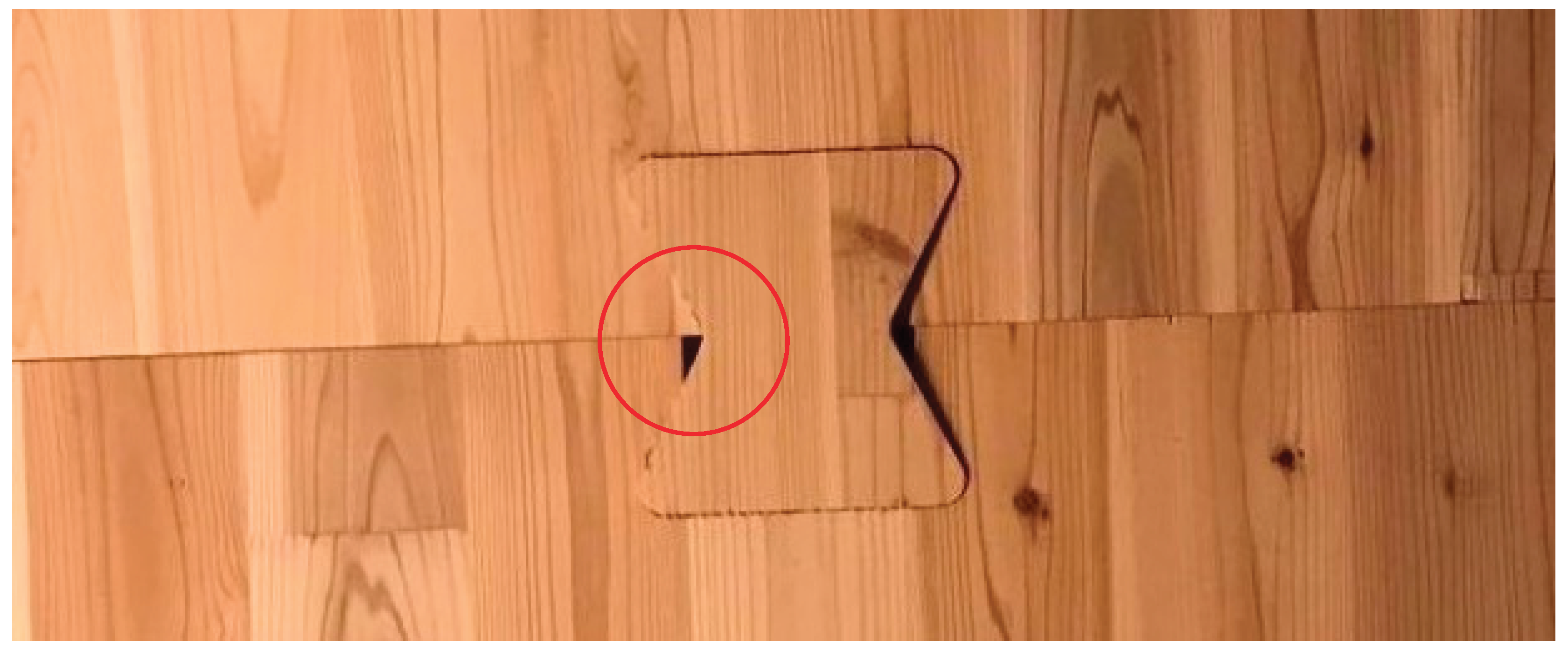
George Nakashima’s 1968 desk incorporated a similar butterfly fitting to carry tensile loads generated by drying shrinkage; however, its bending performance was never characterized. During assembly, some connector keys caused localized chipping along the lamina glue lines. Although this chipping did not match the failure modes observed in tests, it was deemed non-critical and construction continued. Hammer-driven connectors at CLT panel edges can induce rolling-shear damage along lamina layers. Japanese CLT fabrication does not apply epoxy resin to the side faces of the lamina, increasing edge vulnerability. The structural adhesive used between laminations is a resorcinol–phenol co-condensation resin; in tests the adhesive layer fractured before any wood substrate failure, confirming that the adhesive layer is weaker than the timber members under shear and tensile loading.
Figure 14.
George Nakashima’s Butterfly-Fitting Table Joint (Sakura Seisakusho).
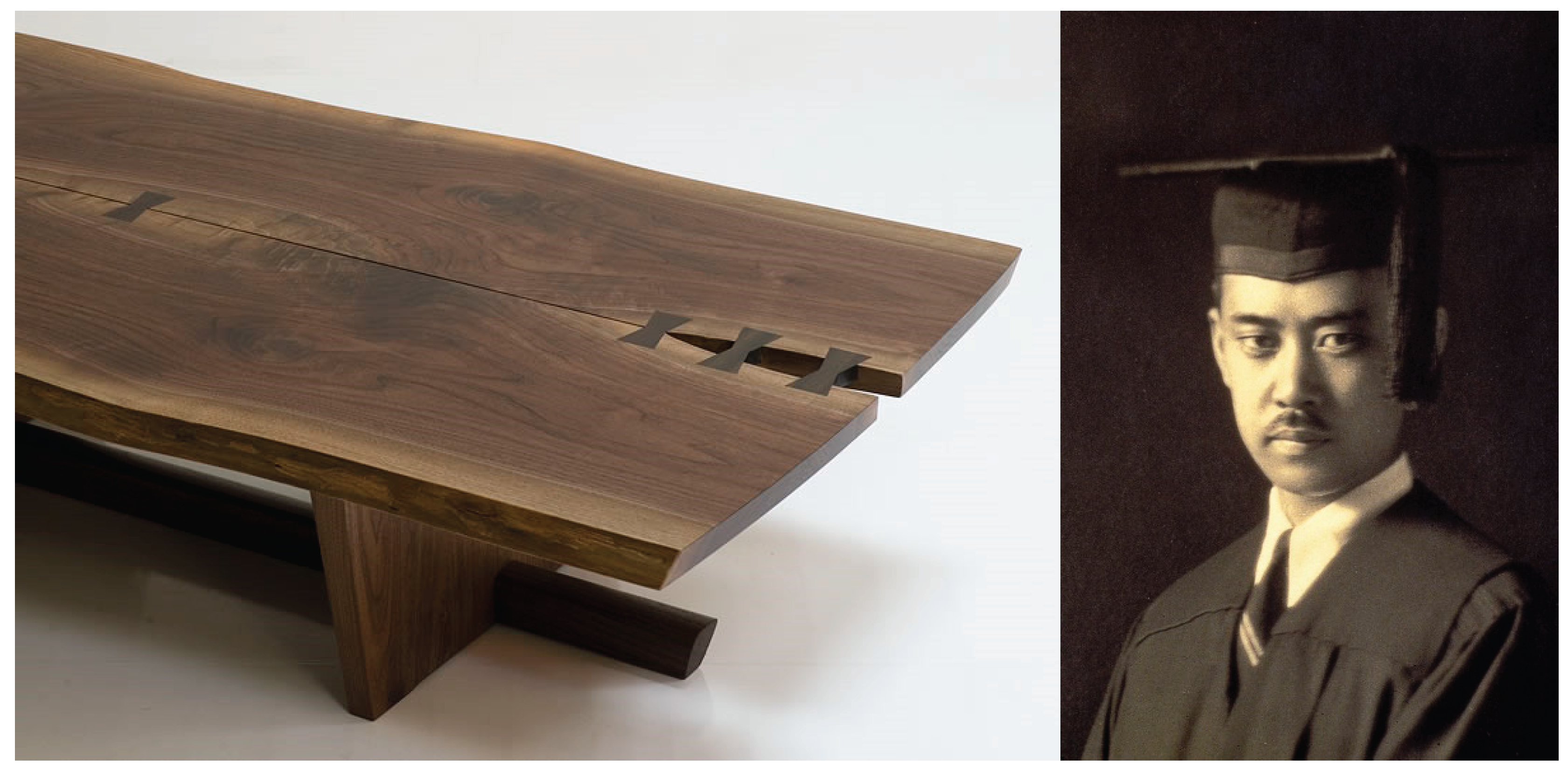
Figure 15.
Localized Lamina Chipping at Connector Key Insertion (Authors).
2.4. Wood and Groundwater Circulation
The building is constructed from locally sourced cedar and cypress and rests on a strip footing bearing on a competent layer of red clay. A three-month well-drilling operation using 100 mm-diameter borings to 100 m tapped Mount Aso’s clean groundwater: geophysical logging and core sampling revealed a gravel stratum to GL –30 m and red-brown Togawa lava deposits to GL –100 m, remnants of Pleistocene pyroclastic flows. During drilling, slurry was lifted to the surface by buoyant rice husks. The stiff strata limited advance to roughly 0.5 m per day. A submersible pump installed at GL –20 m filtered incoming water through the formation, yielding clear, odorless spring water at approximately 200 L/min. This architecture illustrates the continuous cycle of local timber and Mount Aso’s abundant groundwater.
Figure 16.
Rice-Husk Slurry Removal and Groundwater Pumping (Authors).
3. Results
3.1. Experiment Overview
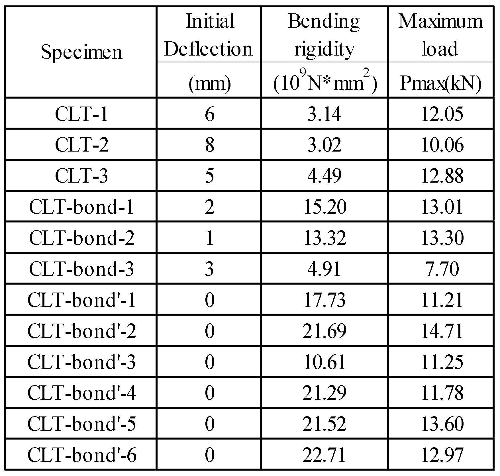
Twelve connector specimens were evaluated for bending strength under four configurations: with and without structural adhesive (polyurethane resin) and with the connector’s strong and weak grain directions aligned to the CLT’s principal axis (Figure 17). Each specimen was seated on a bearing plate and braced with a centrally mounted pantograph to eliminate initial deflection. Four-point loading was applied via a 2 000 kN testing machine at a monotonic displacement rate of 5 mm/min until either a peak load was reached or 50 mm of displacement occurred. Specimen deflection was recorded by a midspan displacement gauge.
Timber fitting connectors marked [ ’’ ] are oriented parallel to the CLT strong-axis direction; absence of [ ’’ ] denotes orientation along the weak axis. [ Bond ] indicates the application of structural adhesive. The test results confirm P max=12.0 kN (average peak load ), and a long term allowable bending strength Ma=1.54 kN·m (Figure 18 and Figure 19). Since the lamina side faces were uncrimped, shear failure of the fitting connector snagging area occurred after rolling shear occurred. Resorcinol-phenol co-condensation resin was used as the structural adhesive joining the laminae. Although a structural adhesive was used, only stiffness increased without any increase in bending capacity. There was also a unit that suffered shear failure of the timber fitting connector after flexural failure of the shear key. The stiffness of the structural adhesive was higher than the stiffness of the timber fitting connector, so there no combined proof stress at the end of the test. Since cracking occurred only in the weak axial direction of the CLT layer, the bearing capacity would have increased if the fittings were in the strong axial direction (Figures 20). Notably, seating the connector on a strong-axis lamina would markedly increase bending capacity. Unlike through-bolts or long screws—which create continuous load paths and require no layer-by-layer orientation fitting connectors in CLT concentrate stresses at each lamina. Therefore, connector design must be studied per layer to avoid weak-axis alignment at the interface. Moreover, for buildings like this one with predominantly unidirectional loading, it may be more rational to adopt a glulam-style layup—stacking laminations all in the fiber direction—instead of cross-lamination, thereby eliminating weak-axis layers and simplifying connector requirements.
Table 2.
Assessment Results.
 |
3.2. Bending Design of Timber Fitting Connector
The Architectural Institute of Japan’s moment-resisting joint equation for compressive stress perpendicular to the grain has been applied directly to our timber fitting connector. However, this formulation considers only three limit states — [1] triangular compressive yielding at the grain displacement, [2] equal compression to the grain displacement, and [3] tensile yielding of the wedge — and thus overestimates the long-term allowable bending moment at Ma=2.16 kN·m. Experimental observations revealed two additional failure modes — [4] flexural shear failure at the connector’s snagging interface and [5] s pure shear failure of the connector body — so these were incorporated into the design criteria. By taking the minimum capacity among all five conditions, the revised design value becomes Ma=1.36 kN·m, closely matching the measured performance.
My=Ny・j
Ny=min(ΣNy,Ny1,Ty2, Qm , Qs)
Ty2=Ae・Fty
Qs=As・fss
3.3. CLT Cost-Reduction Strategy and Carpentry Execution
At the time, CLT was a novel construction method, and contractors were hesitant to procure materials directly without intermediaries. As the client, I assumed the contractor role—purchasing CLT panels and fittings directly from the manufacturer—and performed the carpentry work myself. By separating the CLT works contract from the main building contract and eliminating intermediary fees, CLT framing costs fell to approximately about $200/m², roughly one-third of the original estimate. This reduction was achieved despite post-disaster price inflation following the Kumamoto earthquakes, which had driven up material and labor rates.
All CLT arch modules and superimposed open-work beams were prefabricated at the factory (Figure 21 and Figure 22). Arch CLT (t=150 mm, S60 cedar) and joint jigs were CNC-cut from 3.0m × 12.0m × 0.15 m “mother boards” using DXF layouts provided by the design team, achieving just 6 % waste (20.28 m³ raw to 19.01 m³ installed). Connector mortises were undersized by 1.0 mm to account for post-adhesive swelling; mock-ups confirmed that light “kigoroshi” hammering collapsed cell walls to ensure tight fit and improved glue penetration.
On-site, a crew of five carpenters completed erection in a single day on a narrow lot crisscrossed by overhead power lines. Modules measured 2.75–2.85 m in width and weighed 1.5 t each. A few carpenters guided each arch into place using a nylon sling and hydraulic jacks, then secured interfaces with long screws. Lightweight CLT enabled manual positioning when necessary (Figure 23).
I organized a team of local friends and former collaborators to undertake every phase of the project—from well drilling through carpentry to interior finishing—allocating each task to match individual expertise (Figure 24). By eliminating hierarchies and embracing a flat, collaborative structure, we achieved a creative disaster recovery that honored traditional craftsmanship and maximized efficiency.
Figure 24.
Project Roles: Traditional vs. Author-Led Reconstruction.
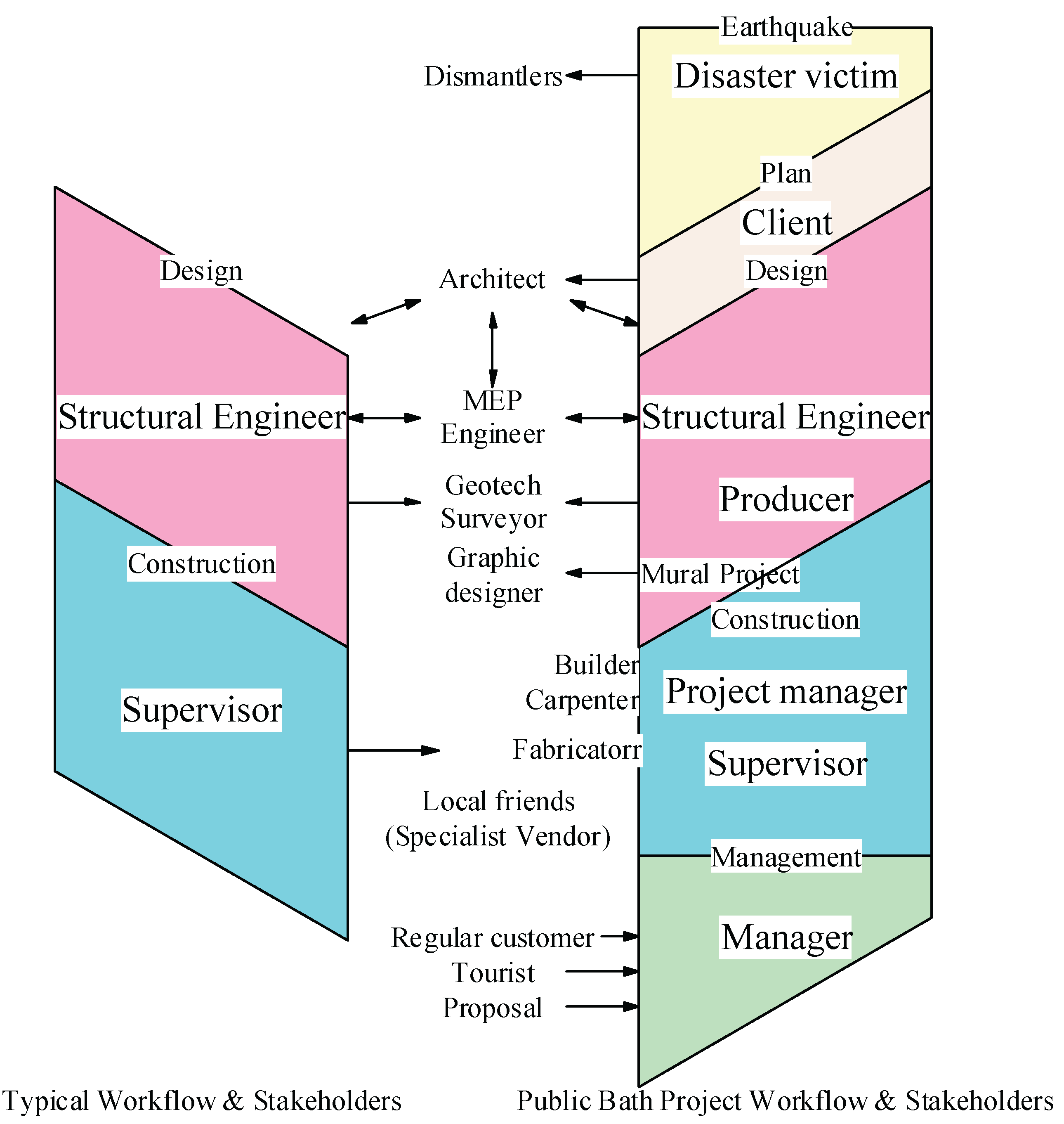
Figure 25.
Public Bath Interior and Street-Facing Exterior (Shigeo Ogawa).

4. Discussion
Timber joint design encompasses numerous configurations, yet the timber fitting connector studied here offers distinct advantages and challenges for both new construction and adaptive reuse—including deconstruction and relocation. In a separate set of our experiments on edge compression of CLT panels, pressed (red and green line) specimens achieved approximately 20 % higher maximum loads compared to non-pressed (blue line) counterparts (Figure 26). In pressed specimens, cracks initiated at the finger-joint of the lowest lamina and propagated upward through adjacent layers, whereas non-pressed specimens exhibited selective propagation along finger-joints (Figure 27). These results of lamina-side compression to mitigate rolling-shear damage and indicate that, when aesthetic sensitivity is paramount, pre-compression of CLT edges is essential to preserve connector integrity.
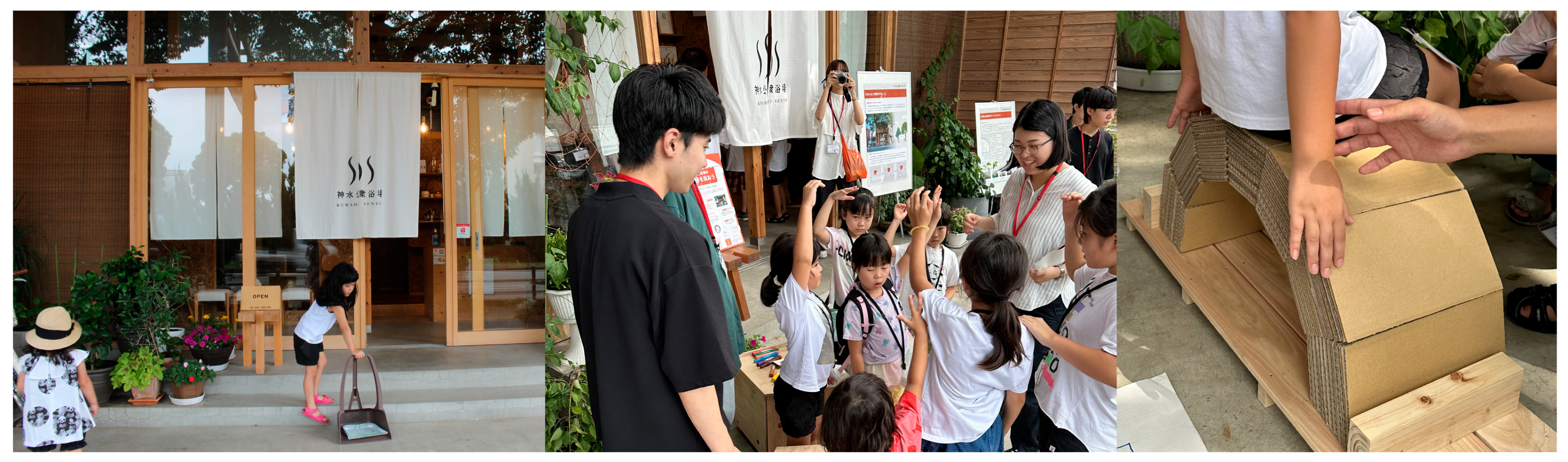
Beyond structural performance, disaster resilience relies equally on social cohesion. Opening the public bath and working behind its counter has woven everyday family life into the routines of our neighbors. We also host workshops with local children several times a year, teaching basic carpentry and disaster preparedness. Familiar faces greeting each other daily transform the bathhouse into an ongoing disaster-readiness exercise.
Figure 28.
Workshops with Local Childre (Authors).
5. Conclusions
In Japan, CLT remains a relatively new building material, and construction firms often transfer procurement risk to intermediaries. As a result, CLT framing costs typically approach those of RC construction. In our project, we overcame this “double ordering” model by separating the CLT works contract and purchasing panels and fittings directly, reducing framing costs to one-third of the original estimate. Rather than proprietary metal connectors, we employed timber fitting connectors that offer significant cost advantages and local manufacturability wherever timber is available. We successfully rebuilt our home. The public bath has been bustling with users, and we look forward to helping community preparedness in the future.
Abbreviations
The following abbreviations are used in this manuscript:
| CLT | Cross Laminated Timber |
References
- MLIT, Criteria for Determining the Degree of Damage to Earthquake-Damaged Buildings and Technical Guidelines for Restoration, Building Disaster Prevention Association: 2-3-20 Toranomon, Minato-ku, Tokyo 105-0001, Japan, 2015; pp. 1-299.
- Akira Wada et al, Design Practice for Engineered Timber Joint, Architectural Institute of Japan: 5-26-20 Shiba, Minato-ku, Tokyo 108-8414, Japan, 2015; pp. 160-178.
Figure 1.
Consecutive Kumamoto earthquake damage (Authors).
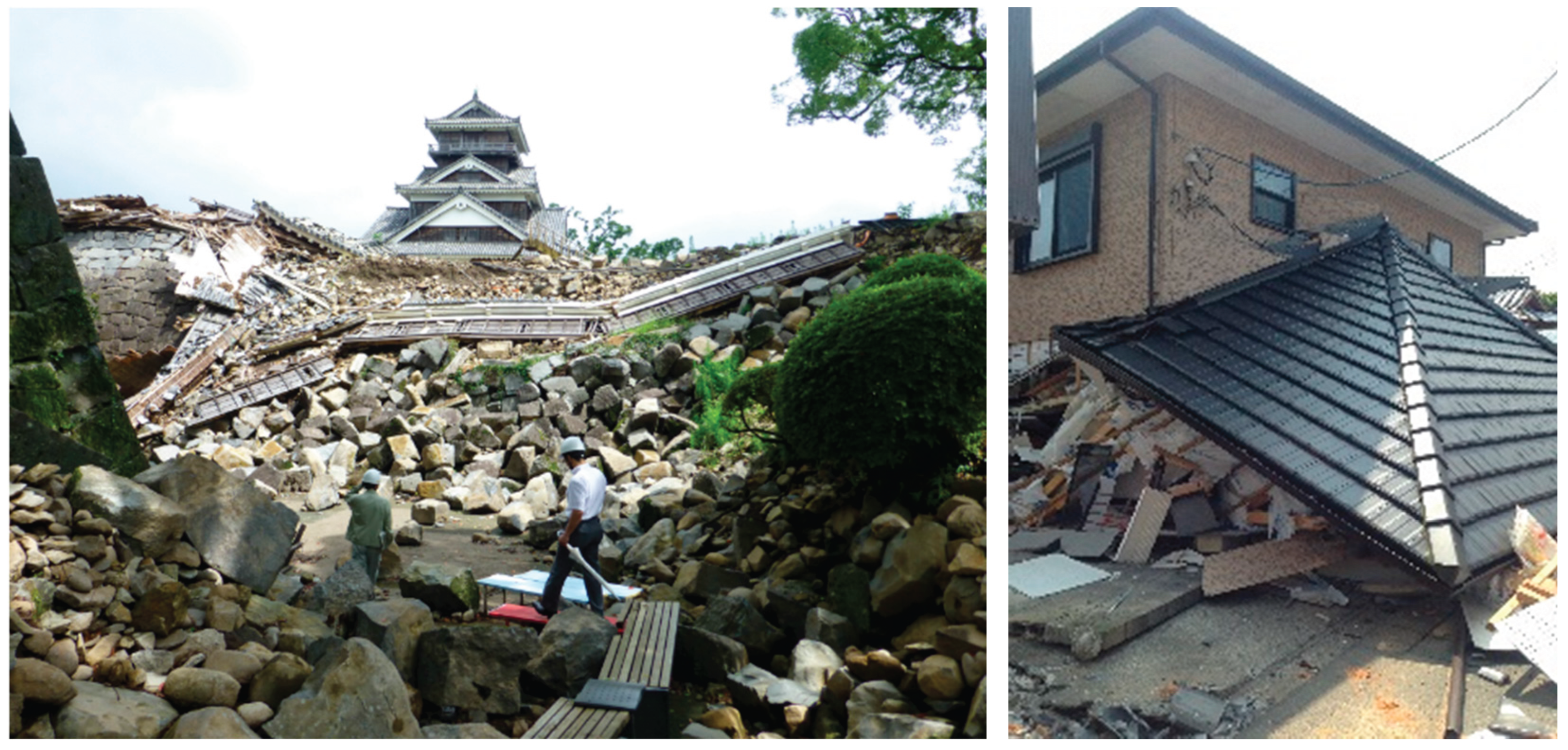
Figure 2.
Public-bathhouse queue following the April 2016 Kumamoto earthquakes (Kumanichi).
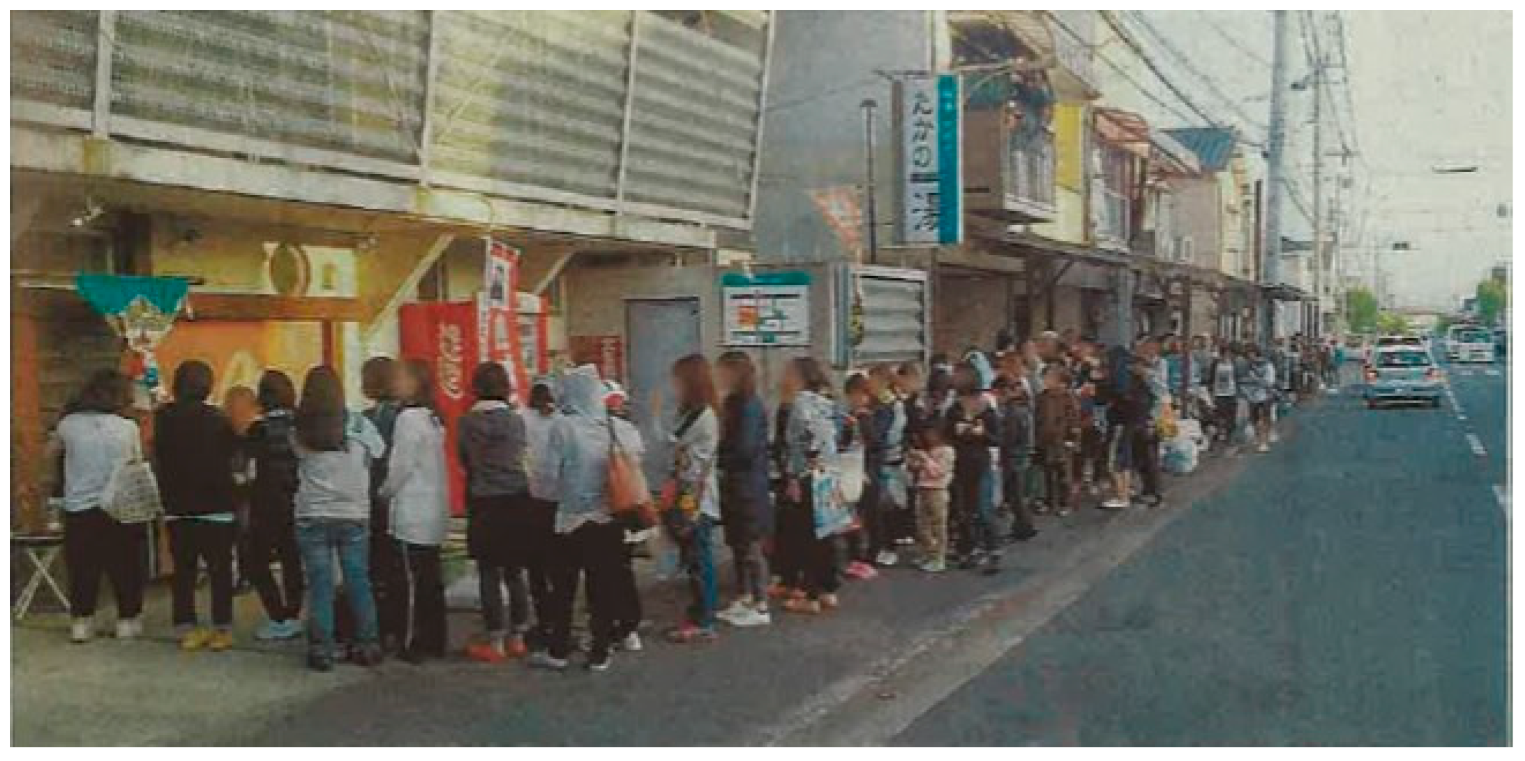
Figure 3.
Rapid post-quake safety-assessment stickers indicating aftershock risk levels.
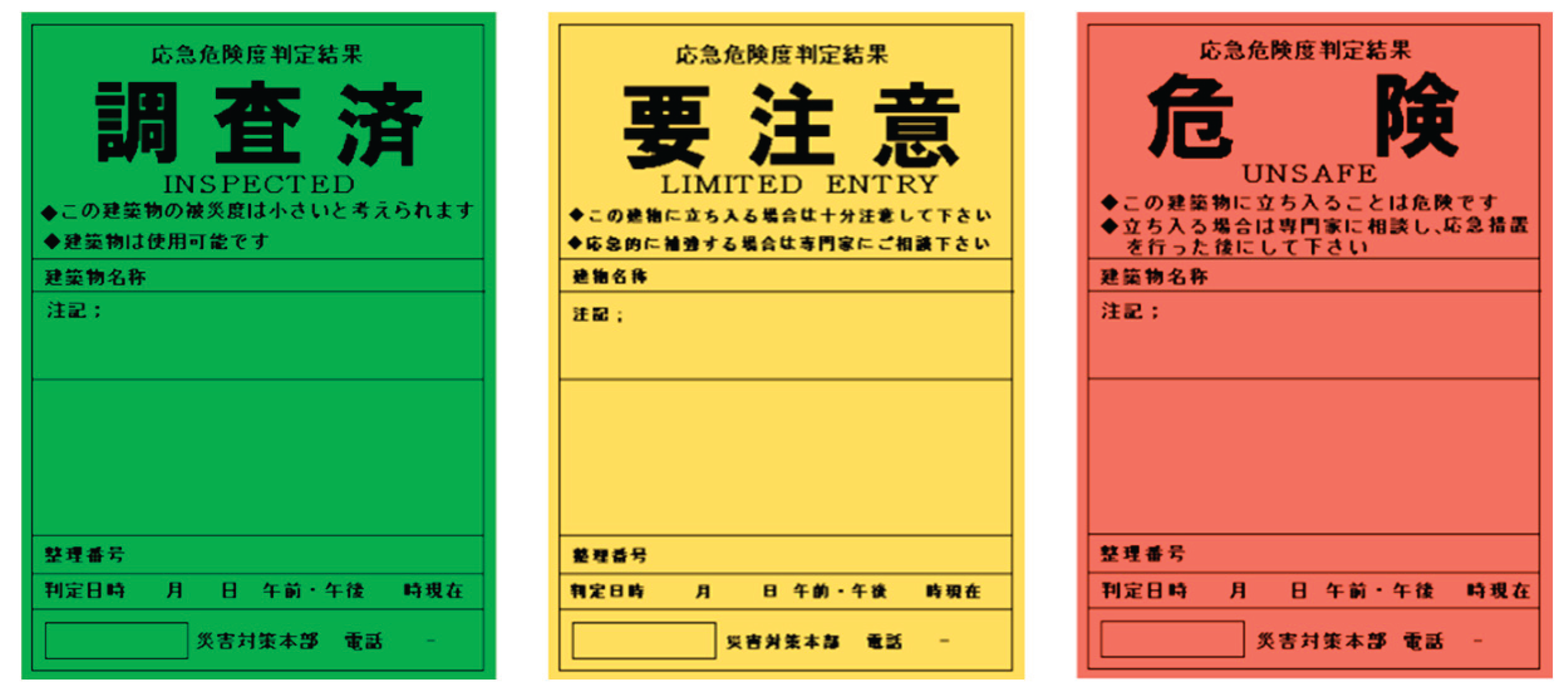
Figure 4.
Networked disaster-prevention city model.
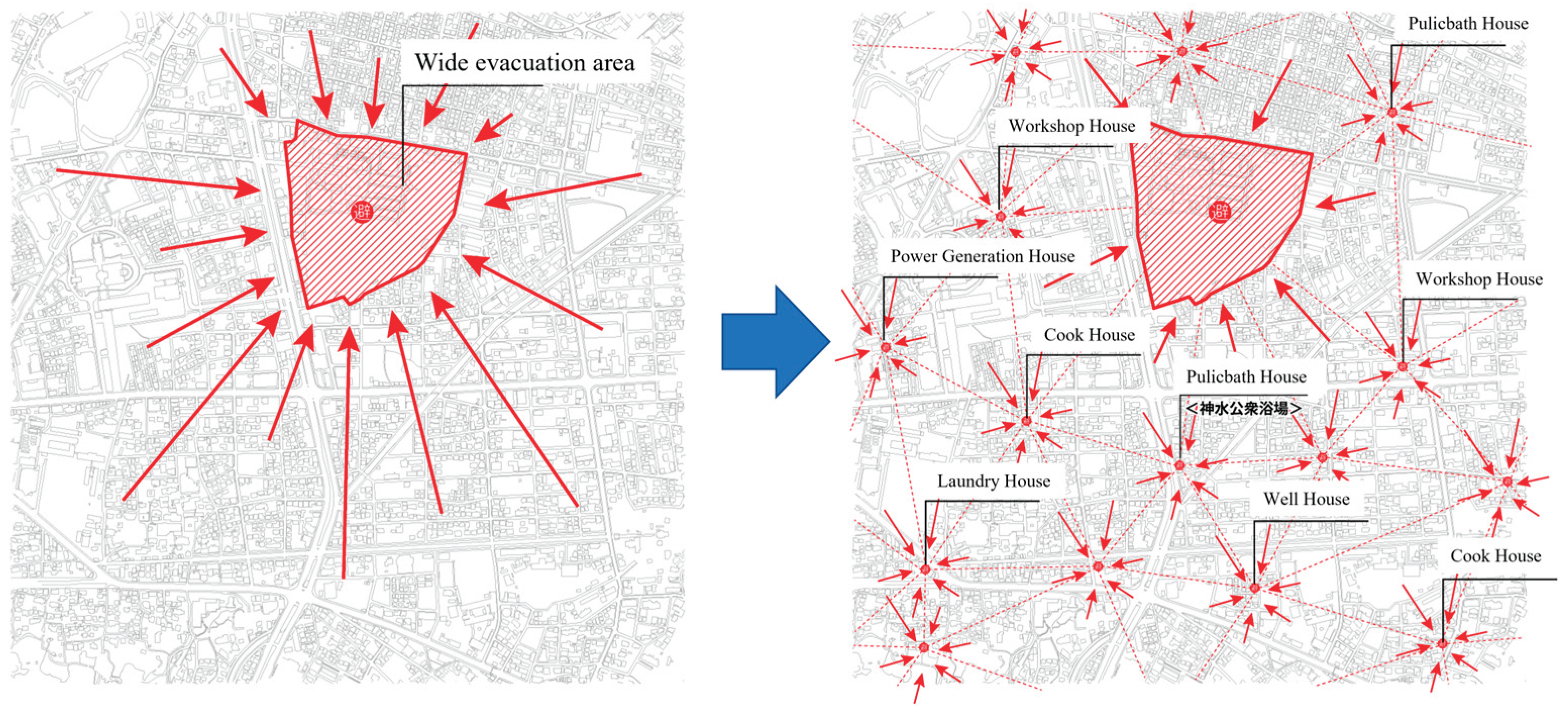
Figure 10.
Axonometric drawing.
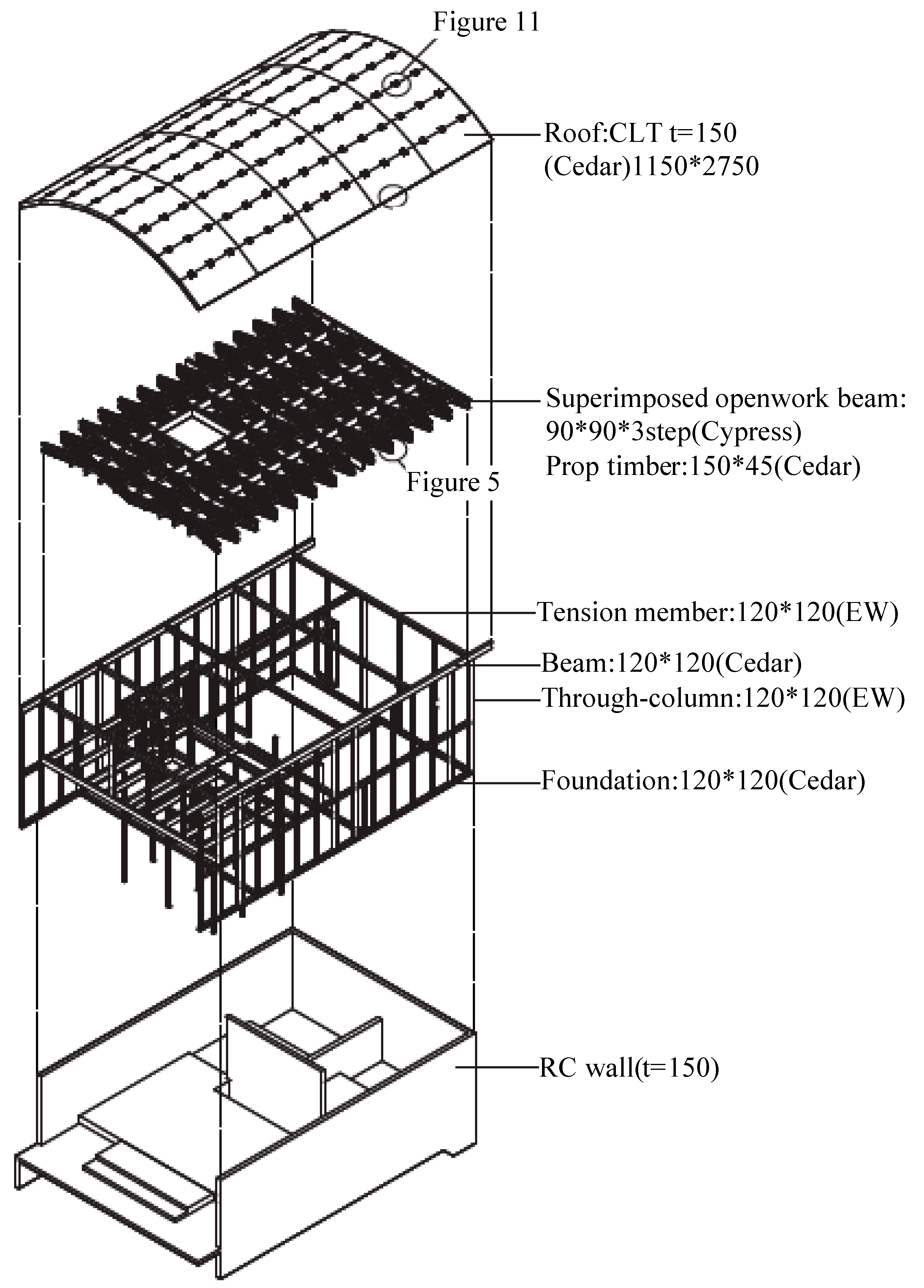
Figure 11.
Fitting-Connector (top) and Tension-Member Joints(bottom).
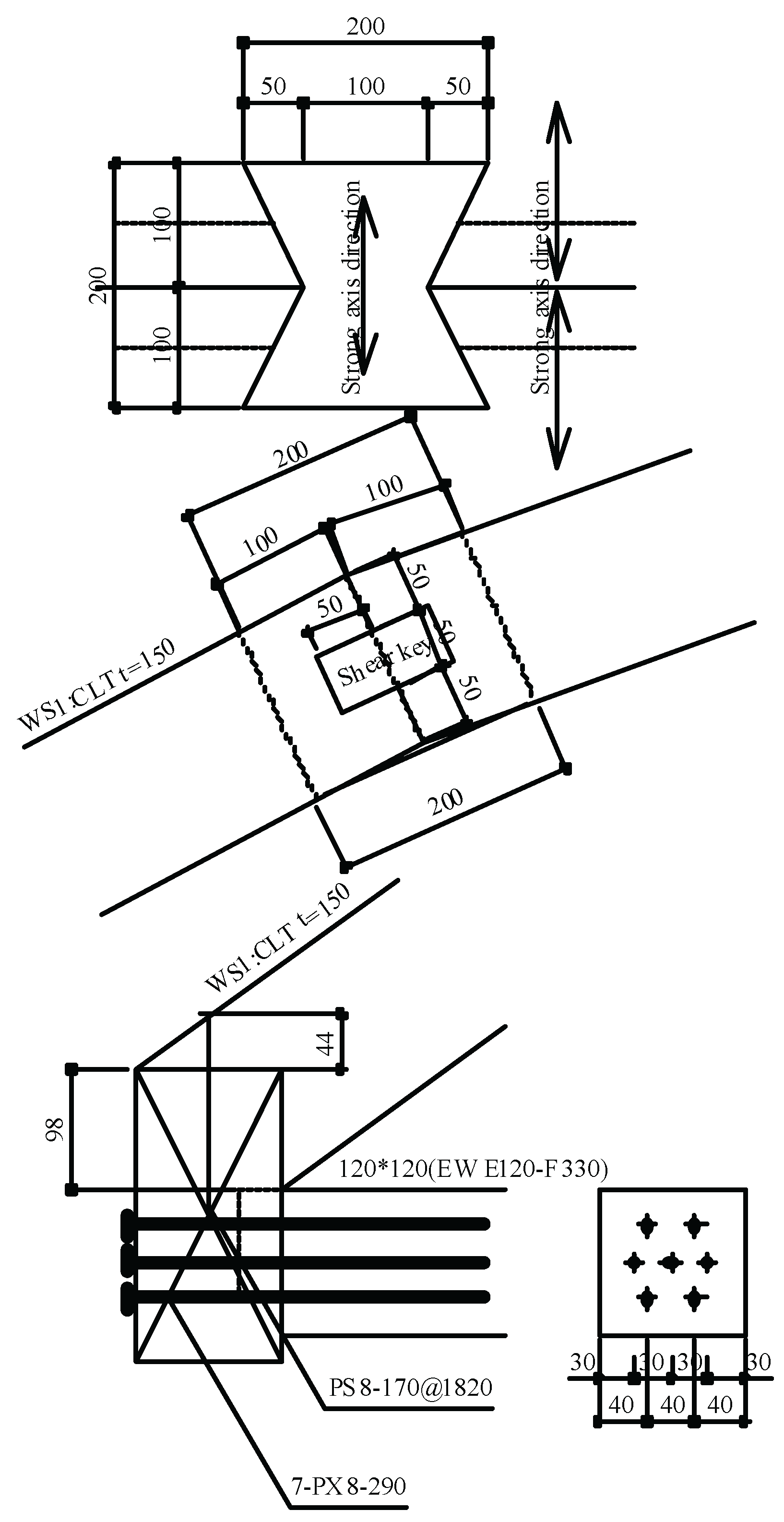
Figure 12.
Force Flow in CLT Arch: Compression and Tension Paths.
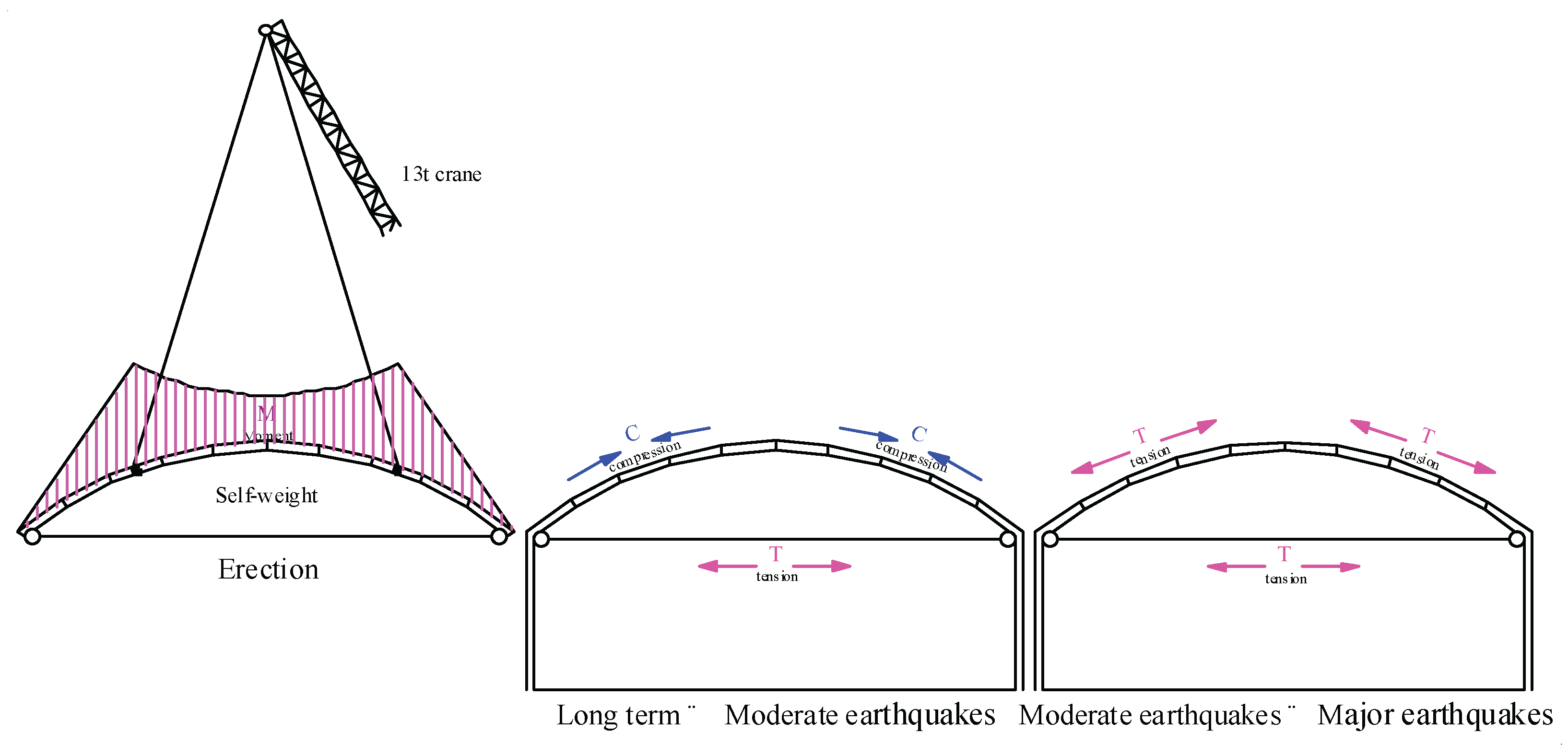
Figure 13.
Force Flow in CLT Arch: Compression and Tension Paths (Authors).
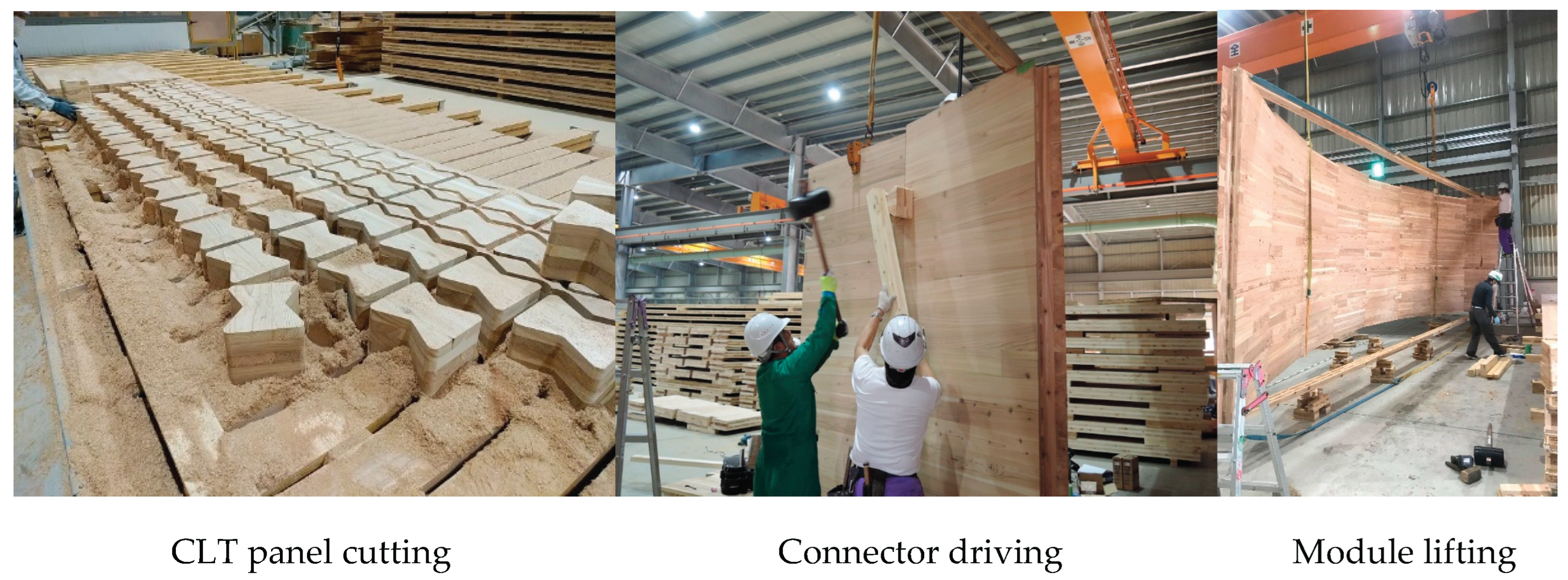
Figure 17.
Bending Test Setup.
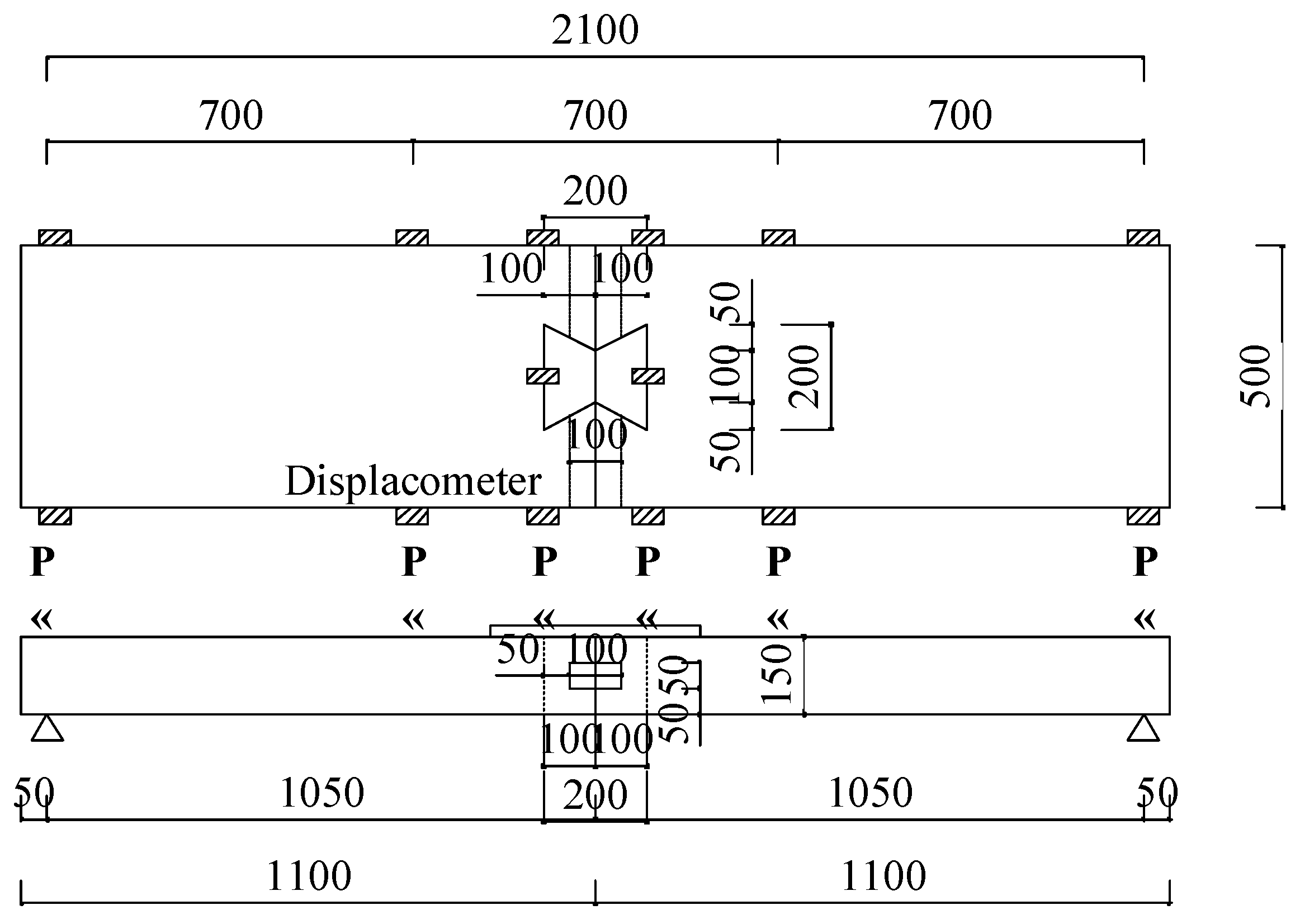
Figure 18.
Flexural Rigidity and Peak Load Results.
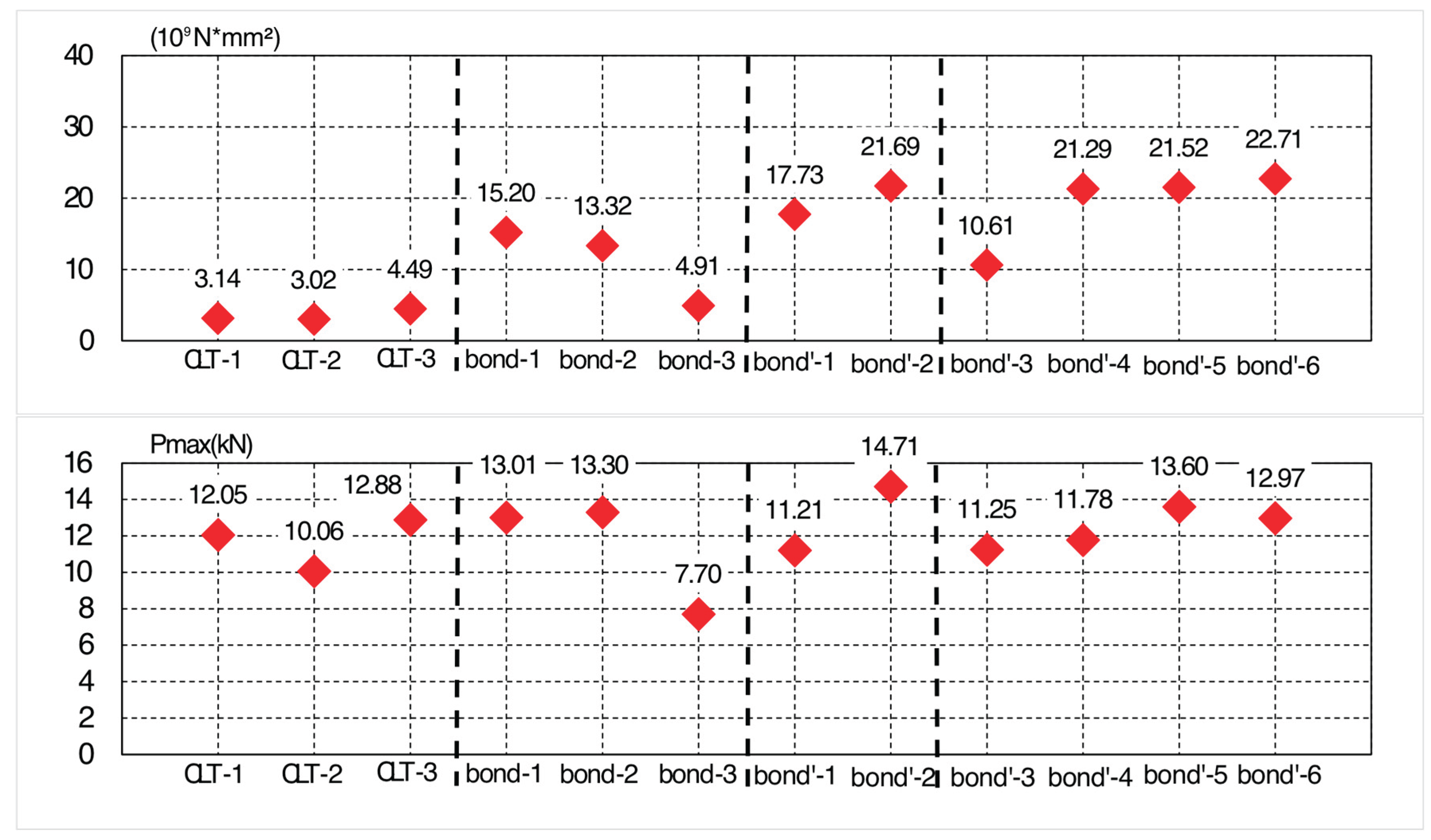
Figure 19.
Load displacement curve.

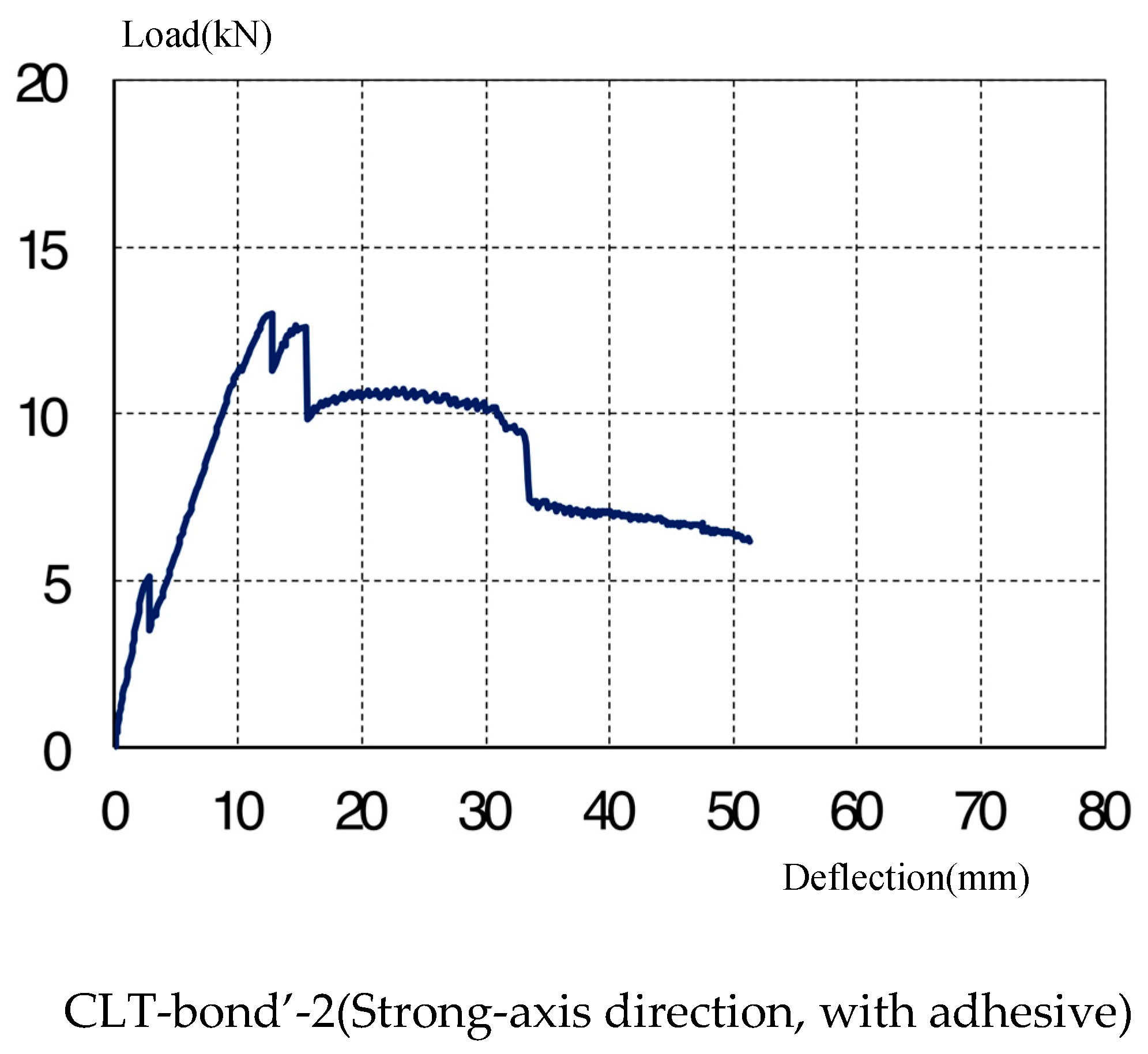
Figure 20.
Specimen after testing (Authors).
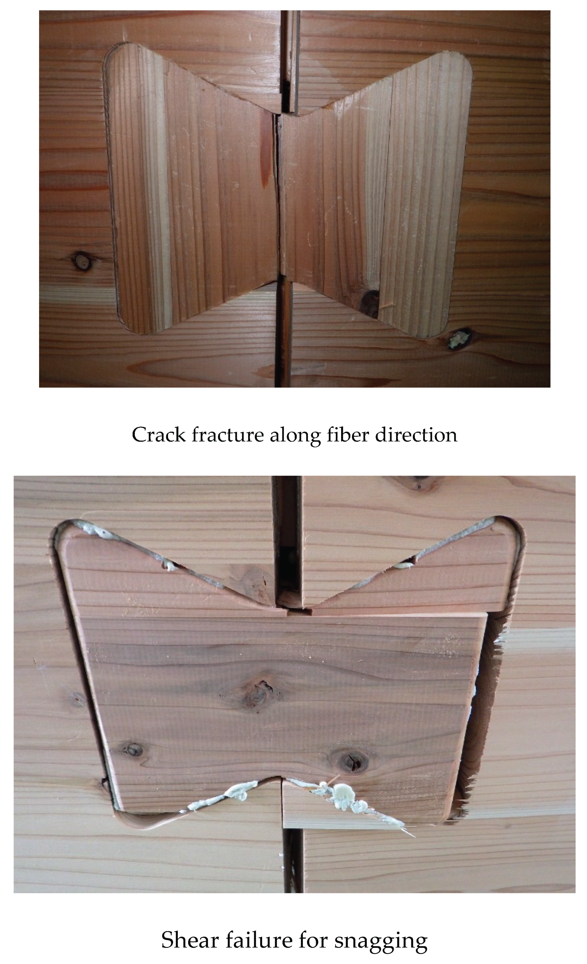
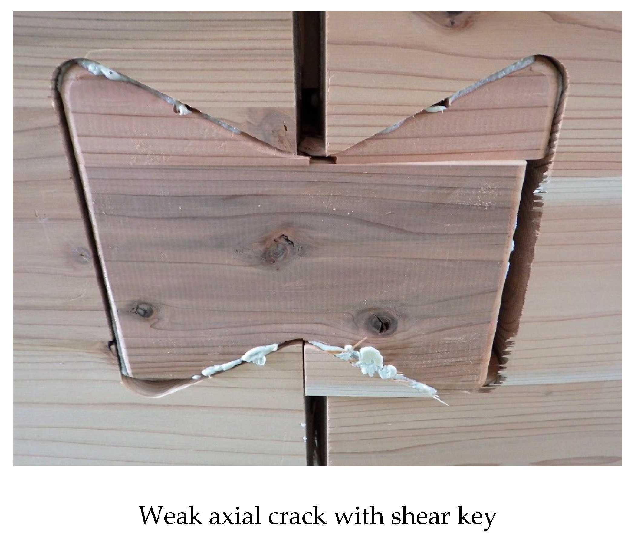
Figure 21.
Fabrication Layout of CLT Arch and Beam Units.
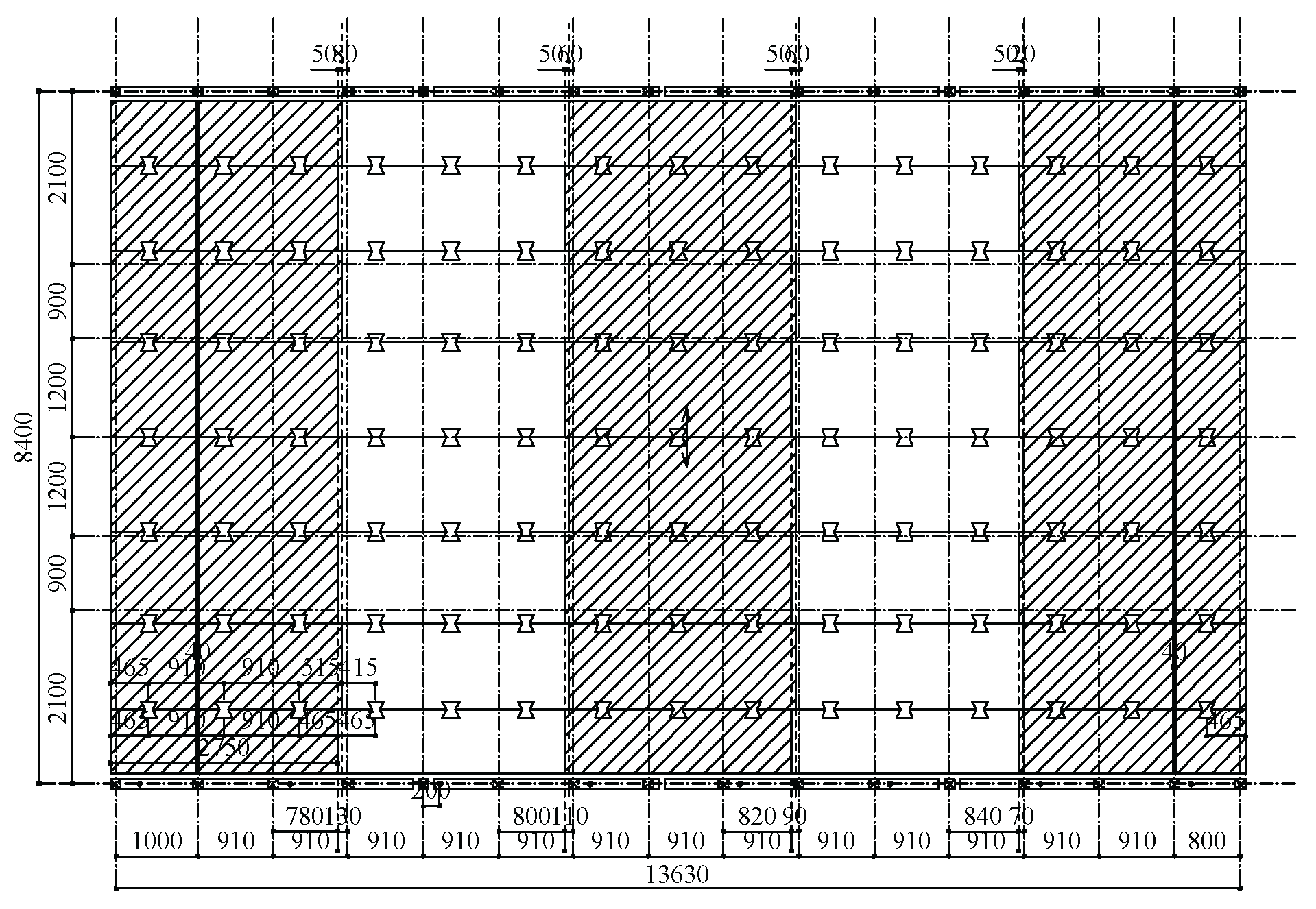
Figure 22.
Single Item.
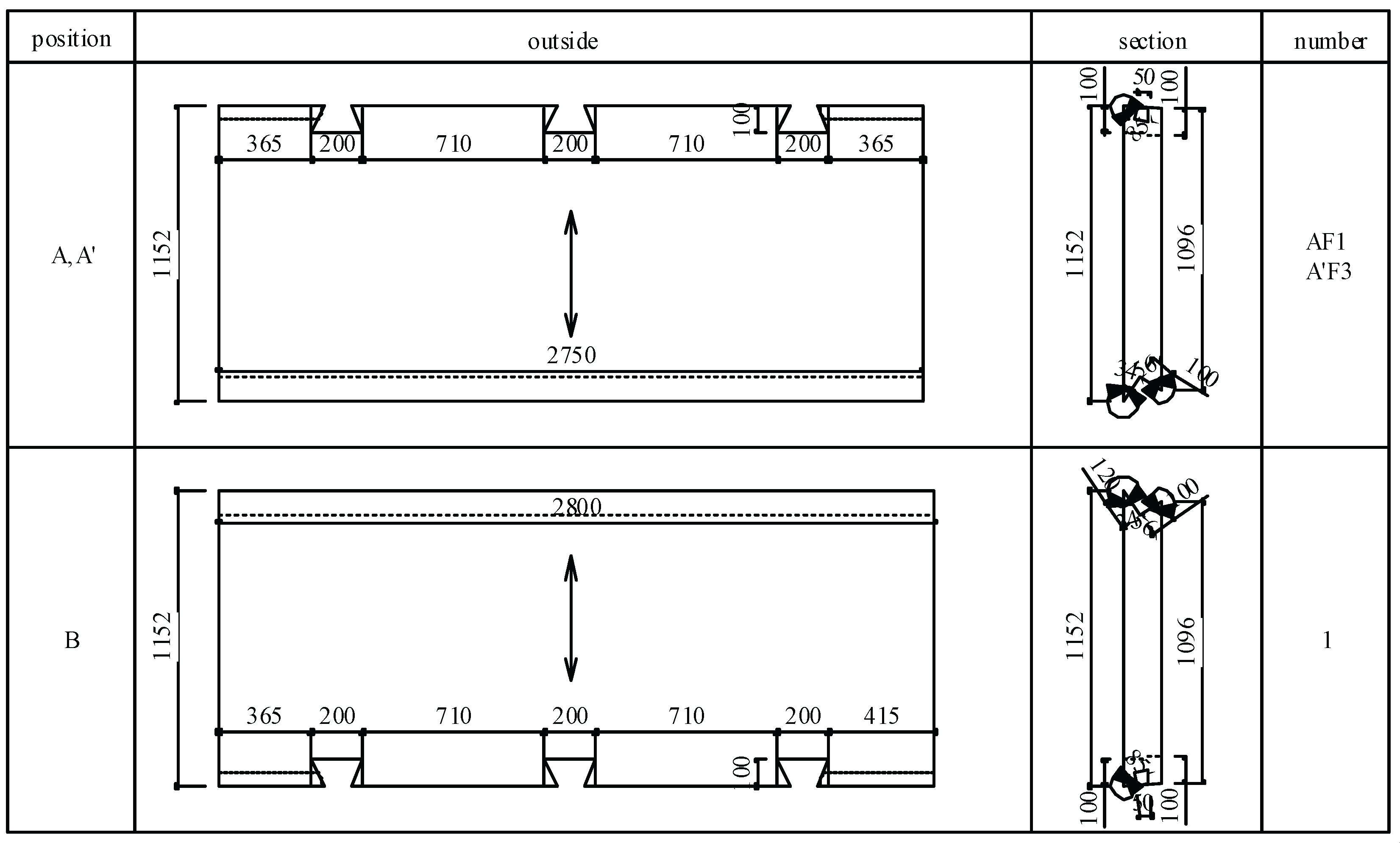
Figure 23.
Erection and Alignment of CLT Arch Modules (Authors).
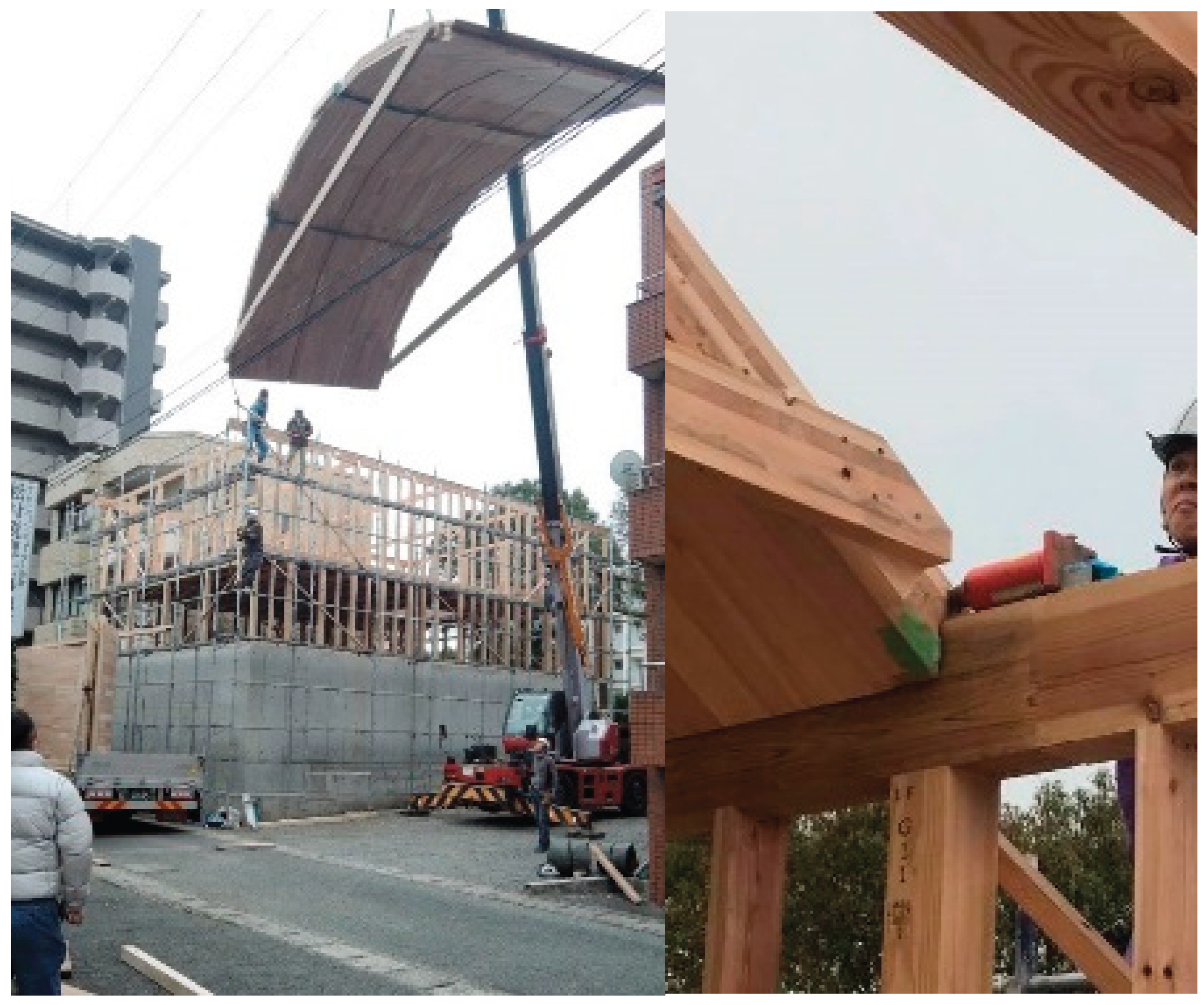
Figure 26.
Load displacement curve.

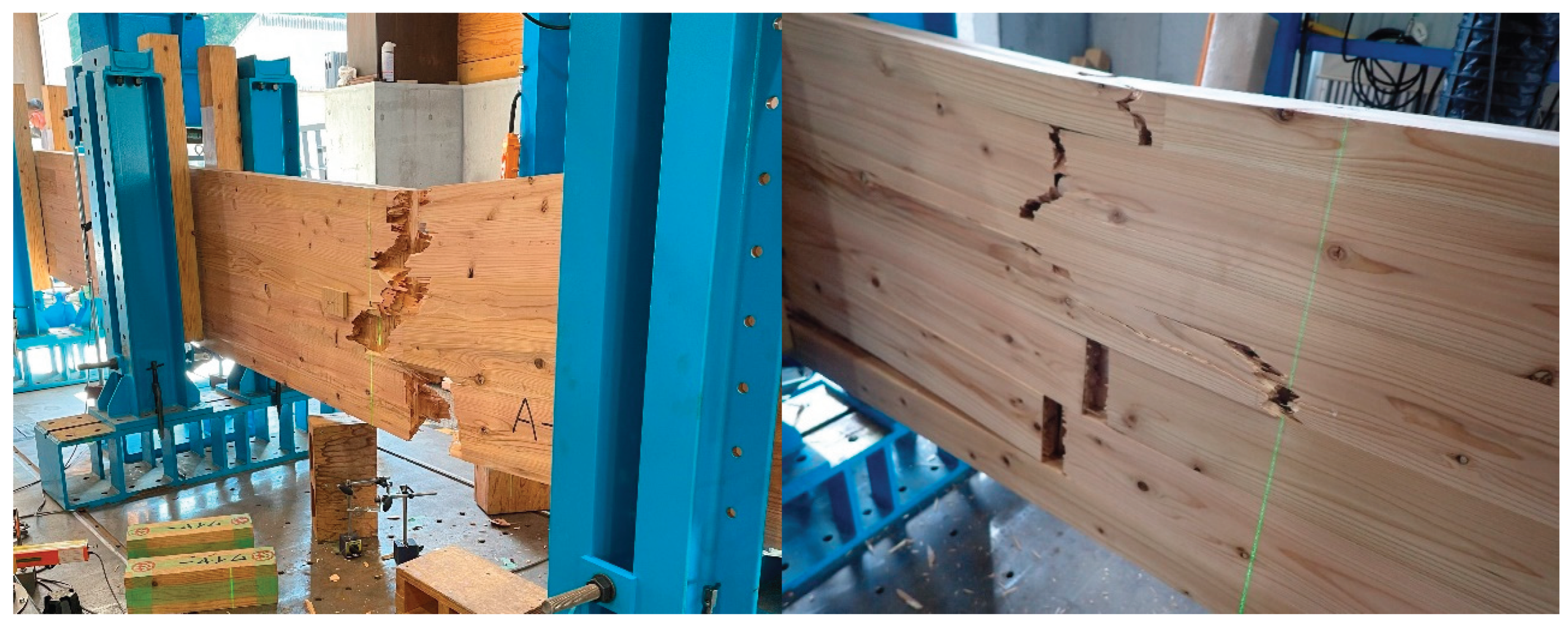
Figure 27.
Failure Modes of Pressed (left) and Unpressed (right) Specimens (Authors).
Disclaimer/Publisher’s Note: The statements, opinions and data contained in all publications are solely those of the individual author(s) and contributor(s) and not of MDPI and/or the editor(s). MDPI and/or the editor(s) disclaim responsibility for any injury to people or property resulting from any ideas, methods, instructions or products referred to in the content. |
© 2025 by the authors. Licensee MDPI, Basel, Switzerland. This article is an open access article distributed under the terms and conditions of the Creative Commons Attribution (CC BY) license (http://creativecommons.org/licenses/by/4.0/).
Copyright: This open access article is published under a Creative Commons CC BY 4.0 license, which permit the free download, distribution, and reuse, provided that the author and preprint are cited in any reuse.


