
Submitted:
22 July 2025
Posted:
22 July 2025
You are already at the latest version
Abstract
Metal-organic frameworks (MOFs) have attracted considerable interest for triboelectric applications due to their high surface area, adjustable porosity, and chemical tunability without altering the crystalline framework. In this work, a hybrid-mode triboelectric nanogenerator (TENG) based on zeolitic imidazolate framework-8 (ZIF-8) was developed and characterized. The system integrates both contact-separation and sliding modes to enhance energy conversion efficiency. Structural and morphological analyses confirmed the successful formation and deposition of ZIF-8 onto the device surface. Density Functional Theory (DFT) calculations revealed a net positive surface charge on the ZIF-8 layer, supporting its favorable triboelectric performance. Polystyrene was used as the counter triboelectric layer, and the ZIF-8/polystyrene configuration achieved that under 2 Hz operation, the hybrid TENG system produced a power density of 87,3 mW/m² with a 236 MΩ load, ensuring stable energy delivery. When the load was removed (open-circuit), the power density increased to 803 mW/m², attributed to higher surface charge accumulation due to negligible current flow. These results confirm the system’s effective dual-mode energy harvesting capability. The contact mode primarily contributes to high voltage generation, while the sliding mode enables continuous current output. The TENG device was further adapted for harvesting mechanical energy from water waves by mounting it onto a floating platform, where both vertical and horizontal motions of waves drive the dual-mode system.
Keywords:
Metal–organic frameworks (MOFs)
; Zeolitic imidazolate framework‑8 (ZIF‑8)
; Hybrid‑mode triboelectric nanogenerator (TENG)
; Contact–separation and sliding energy‑conversion modes
; Density functional th
1. Introduction
The rapid advancement of modern technologies, especially in areas such as the Internet of Things (IoT), artificial intelligence (AI), and human–machine interfaces, has led to the proliferation of compact, lightweight, and multifunctional electronic devices [1,2]. These innovations are integral to health monitoring, wearable electronics, and autonomous sensing systems. However, most of these applications still rely heavily on conventional batteries, which pose challenges such as limited lifespan, bulky size, and environmental pollution due to disposal [3]. Although alternative energy generation methods such as solar cells, thermoelectric generators (TEGs), and electromagnetic generators (EMGs) have been explored, their inherent limitations such as dependence on environmental conditions, rigid structures, or complex fabrication—restrict their practicality in flexible and miniaturized electronics [4].
To overcome these limitations, self-powered technologies have garnered increasing attention. Nanogenerators, which convert mechanical energy from the ambient environment into electrical energy, have emerged as promising candidates. Among them, triboelectric nanogenerators (TENGs) are particularly notable due to their simple architecture, wide material compatibility, low cost, and high voltage output [5,6]. Since their first demonstration by Prof. Z. L. Wang in 2012, TENGs have been extensively investigated for powering low-energy electronics, autonomous sensors, and wearable systems [7,8]. TENGs operate based on the triboelectric effect and electrostatic induction, where charges are transferred when two materials with different electron affinities contact and separate [9,10,11]. Four fundamental operation modes exist: vertical contact–separation (VCS), lateral sliding, single-electrode, and freestanding modes, with VCS being most widely adopted due to its ease of implementation and mechanical stability [12,13].
The efficiency of TENGs depends heavily on the selection of triboelectric materials. While polymers and metals are commonly used, recent research has focused on advanced materials such as metal-organic frameworks (MOFs) to enhance output performance. MOFs are crystalline porous materials formed by the coordination of metal ions or clusters with organic ligands, offering high surface area, tunable porosity, and excellent structural and chemical stability. These characteristics make MOFs highly attractive for applications in sensing and more recently, energy harvesting systems [14,15].
Among MOFs, zeolitic imidazolate frameworks (ZIFs) have shown particular promise in TENG applications. ZIFs combine the advantages of conventional MOFs with superior thermal stability and tunable electronic properties and have been investigated for their ability to serve as triboelectric layers due to their ordered structures, high crystallinity, and compatibility with flexible device configurations. Nevertheless, the full exploitation of ZIFs in triboelectric energy harvesting remains limited, especially in terms of thin-film processing, surface engineering, and dual-mode (hybrid) energy generation designs [16,17,18].
In this study, ZIF-8 was synthesized and molecular and electronic structurally, verified using single-crystal X-ray diffraction (SCXRD) and Density Functional Theory (DFT), respectively. ZIF-8 was deposited as a thin film onto copper tape and characterized by atomic force microscopy (AFM) , Scanning Electron Microscopy (SEM) and Energy dispersive X-ray (EDX) analysis. A triboelectric nanogenerator was then fabricated using ZIF-8 as the electronegative layer and polystyrene (oven bag) as the electropositive counterpart, based on triboelectric series compatibility. The device incorporated two copper electrodes and was engineered to operate in a hybrid mode combining vertical contact-separation and lateral sliding. In contact-separation mode, vertical movement between ZIF-8/polystyrene and copper surfaces produces charge transfer and voltage spikes, while in sliding mode, the lateral displacement of these layers across copper strips generates continuous current.
The hybrid triboelectric nanogenerator (TENG) system designed in this study operates on the combined principles of vertical contact–separation and lateral sliding modes. Under mechanical excitation, when the upper dielectric layer applies a controlled force onto the lower triboelectric surface, a distinct contact–separation event occurs at the base interface, promoting efficient charge transfer due to direct contact. Simultaneously, on the lateral surfaces, relative motion between adjacent triboelectric strips facilitates continuous charge generation through the sliding mechanism. This dual-mode operation is anticipated to be effectively driven by the multi-directional forces exerted by water waves, enabling both vertical compression and horizontal displacement of the device components [19,20,21,22,23,24,25,26].
Electrical measurements performed at 2 Hz revealed a peak voltage of 80 V, maximum current of 1.1 µA, and power density of 87.3 mW/m² using a 236 MΩ load. These findings underline the significant potential of ZIF-based hybrid TENGs for sustainable, self-powered systems, particularly in marine applications where water-wave frequencies are similarly low and irregular [25,26,27]. Upon removal of the resistive load (open-circuit condition), the system exhibited a significantly higher power density of 803 mW/m² with an open-circuit voltage of 195 V and current of 3.55 µA highlighting the TENG’s intrinsic ability to generate high surface charge potentials when current draw is minimized [28]. This notable increase in open-circuit power density can be attributed to the accumulation of surface charges under hybrid-mode excitation. Together, these results validate the hybrid TENG’s capacity to efficiently harvest ambient mechanical energy from low-frequency, multidirectional forces such as those generated by ocean waves, offering both instantaneous high-voltage generation and sustained current flow ideal for marine sensing and power electronics.
2. Result and Discussion
2.1. Crystallographic Results
X-ray diffraction analysis confirmed that ZIF-8 crystallizes in the cubic I-43m space group, with unit-cell parameters closely matching those reported for solvothermally synthesized zeolitic frameworks [30,31] Examination of the ORTEP diagram (Figure 1) and refined bond lengths/angles (Table 1) demonstrates each Zn1 center in a distorted tetrahedral coordination by four imidazolate nitrogen atoms—an arrangement that extends into a rigid, three-dimensional network [32,33,34]. This robust architecture, further reinforced by peripheral methyl substituents on the imidazolate linkers, prevents pore collapse and limits framework interpenetration, thereby preserving high surface area and facilitating efficient charge transfer for TENG applications [35,36].
The repetitive hexagonal packing of ZIF-8 yields a highly ordered, porous network in which Zn centers are bridged by imidazolate ligands to form rigid, crystalline frameworks suited for TENG applications . Figure 2 demonstrates projection of the ZIF-8 framework along various crystallographic planes ((010), (001), and (011)) highlighting the tetrahedral Zn–Imidazolate cages. The regular nano-sized cavities and channels confer high surface area, enhancing charge separation and storage during repeated contact and separation cycles [27]. This structural rigidity and symmetry also impart exceptional mechanical and thermal stability, ensuring long-term durability under the multi-directional forces encountered in marine environments [37,38]. Furthermore, the interconnected Zn–N bonding network facilitates slight modulation of electron mobility, which can improve the efficiency of triboelectric charge transfer [26]. Collectively, these attributes make ZIF-8’s crystalline packing an ideal candidate for robust, high-performance hybrid TENG designs.
The open framework with interconnected pores allows the material to trap air or other molecules, which can improve dielectric properties. Higher dielectric constants can lead to more effective charge transfer in a TENG, boosting output performance.
2.2. Theoretical Results
DGTZVP (Double-Zeta Valence Polarization) is frequently preferred in the calculations of metal-containing complexes. It is a good choice for providing greater accuracy in the valence orbitals of metals. The molecule is neutral with a total charge of 0, and the spin state is a singlet, indicating that all electrons are paired. At the optimization stage, a specific algorithm updates the geometry of the molecule step by step and ensures energy minimization: Forces (gradients) are calculated for each atom in the molecule. Atoms are moved according to the influence of these forces. The total energy of the system is calculated at each step. This process is repeated until the energy minimum is reached. Combined electronic and spectroscopic characterization of ZIF-8 given in Figure 6.
Mulliken charge analysis reveals that the central Zn atom in ZIF-8 carries a significant positive charge (+0.417), while electronegative imidazolate nitrogens exhibit negative charges (e.g., −0.200), reflecting their stronger electron-withdrawing character [39,40]. This polarized charge distribution creates distinct electrophilic and nucleophilic sites, which can govern intermolecular interactions such as hydrogen bonding and electrostatic adhesion [41]. In the context of TENG devices, the balanced arrangement of positive and negative surface charges enhances triboelectric charge separation and transfer, thereby improving output performance [15,26].
The DFT-calculated electrostatic potential (ESP) surface of ZIF-8 reveals pronounced negative regions around imidazolate nitrogens and positive regions near Zn centers, underscoring its intrinsic electrophilic and nucleophilic sites . This polarity enhances surface charge density and facilitates efficient electron transfer during triboelectric contact–separation, leading to higher energy output in TENG devices [42,43]. Additionally, ZIF-8’s robust chemical stability preserves its ESP profile and structural integrity under repeated mechanical stress, ensuring durable, long-term performance.
The HOMO in ZIF-8 given in Figure 3 is predominantly localized on the imidazolate ligands, serving as electron-donating (nucleophilic) sites, while the LUMO spans toward zinc centers, providing electron-accepting (electrophilic) regions . This balanced dual functionality creates pronounced electronic polarization, enhancing dipolar interactions with contacting materials and thereby improving charge separation and retention in TENG devices . Furthermore, the calculated bandgap of 0.79 eV indicates high charge-transfer efficiency, as the narrow gap facilitates facile electron excitation from HOMO to LUMO, promoting efficient electron mobility during triboelectric operation [44].
The FTIR spectrum of ZIF-8 (Zeolitic Imidazolate Framework-8) reveals critical insights into its structural and chemical characteristics (Figure 3). Vibrational modes observed below 3000 cm⁻¹ correspond to C–H stretching vibrations, highlighting the aromatic nature of the imidazolate linkers . The spectral region between 500 cm⁻¹ and 1500 cm⁻¹ features lattice vibrations, metal–ligand interactions, and functional-group contributions characteristic of the ZIF-8 framework . Sharp and intense peaks within the 1000–1500 cm⁻¹ range arise from imidazolate ring vibrations, reflecting the strong coordination between Zn²⁺ ions and the imidazolate ligands, while distinct Zn–N stretching bands confirm the coordination framework structure [17]. The ε values (M⁻¹ cm⁻¹) indicate the absorptivity of specific molecular bonds, and the D values (10⁻⁴⁰ esu² cm²) provide insights into dipole-moment variations, highlighting the polarizability and IR-active vibrational modes. The narrow, well-defined peaks across the spectrum underscore ZIF-8’s high crystallinity and structural symmetry, confirming its robust and ordered framework.
2.3. SEM-Based Surface Topography and Morphology
SEM micrographs show well-defined ZIF-8 polyhedral crystals (200–600 nm) aggregating into loosely bound clusters (up to several µm), yielding a highly rough and porous surface that enhances contact electrification by increasing interface area (Figure 4) [45]. EDS mapping confirms a uniform Zn–N elemental distribution (~20.6 wt% Zn, 10.5 wt% N) consistent with the Zn–imidazolate framework, with C and O signals reflecting the organic linkers and residual moisture (Figure 5) [46]. The characteristic morphology and homogeneous composition indicate successful ZIF-8 synthesis and imply that its textured surface will maximize charge generation in TENG applications. Details about the concept are given in Figure 7 and 8.
2.4. AFM-Based Surface Topography and Morphology
The AFM scans in Figure 16, each covering a 5 µm × 5 µm area and acquired in forward-scan contact mode with line-fit leveling, reveal markedly different surface morphologies for ZIF-8 (Figure 6) [47,48]. The AFM topography of the uncoated copper band exhibits a largely smooth, anisotropic surface with height fluctuations confined within approximately ±20 nm of the mean plane. The line-fit profile reveals gentle undulations (peaks up to ~+15 nm and valleys down to ~–21 nm) but no pronounced protrusions or depressions. Correspondingly, the amplitude channel shows only minor deflection variations around zero, indicating a consistent tip–sample interaction force and little change in contact stiffness across the scan area. The phase image remains essentially featureless, with phase values tightly clustered around the baseline, reflecting a chemically and mechanically uniform metal surface that produces negligible energy dissipation contrast [49].
ZIF-8 Coated Surface (With MOF): In stark contrast, the AFM maps of the copper band after ZIF-8 deposition reveal a highly textured morphology characterized by discrete crystalline aggregates rising up to ~+60 nm above the mean plane and troughs down to ~–10 nm. The three-dimensional topography highlights nodular features and porous edges consistent with polyhedral ZIF-8 crystallites. The amplitude signal exhibits pronounced local variations as large as ±2 nA equivalent demonstrating the probe’s traversal of steep slopes and rough MOF facets. Although the phase contrast remains relatively subtle, slight phase shifts correlate with the boundaries of MOF clusters, suggesting local changes in mechanical stiffness or adhesion at the MOF–metal interface. Overall, the ZIF-8 thin film imparts a dramatically increased surface roughness and heterogeneity, which is expected to significantly enhance contact area and charge generation in triboelectric applications.
2.5. Electrical Output Performance of the Polystyrene Hybrid-Mode TENG with Dual Copper Electrodes
The electrical output performance of the ZIF-MOF-integrated triboelectric nanogenerator (TENG) was systematically investigated under vertical contact-separation mode and sliding mode using a finger tap. Key performance metrics including open-circuit voltage (VOC), short-circuit current (ISC), and power density (P) were evaluated under a consistent load resistance and mechanical stimulation conditions (frequency: 2 Hz, force: 10 N). A hybrid-mode TENG was fabricated using polystyrene as the dielectric medium. The bottom electrode comprises seven copper strips, each covering an active area of 5.85 cm², while seven lateral copper strips of 2.4 cm² each are mounted on the sidewalls given in Figure 7. Polystyrene was selected for its favorable triboelectric properties, mechanical robustness, and ease of patterning into thin films. Under combined vertical contact–separation and lateral sliding motions, this configuration maximizes interfacial charge transfer: the large bottom strips capture normal pressure-induced charge while the smaller sidewall strips harvest additional energy from tangential displacement. Consequently, the polystyrene-based hybrid TENG demonstrates enhanced electrical output compared to single-mode counterparts.
The time-series traces in Figure 8 illustrate the real-time performance of the hybrid-mode TENG over a 30 s interval. Voltage vs time grapgh shows the open-circuit voltage oscillating erratically between –200 V and +200 V, with peak excursions reaching the envelope limits under the combined contact–separation and sliding mechanisms. In current vs time graph, the corresponding current waveform peaks at approximately ±4 µA, with zero-crossings tightly aligned to the voltage nodes, confirming an Ohmic relationship through the connected load. Finally, power density vs time shows plots the instantaneous power density (P = V·I normalized to a maximum of 803 mW/m²), where sporadic spikes of over 700 mW/m² occur during the highest-voltage events, while low-amplitude intervals produce negligible output. Collectively, these data demonstrate the TENG’s ability to generate substantial bursts of electrical energy from irregular mechanical inputs, underscoring the efficacy of the hybrid configuration in maximizing both voltage and current outputs for sustainable energy harvesting.
Under a matched 236 MΩ load at 2 Hz, the ZIF-8/polystyrene hybrid TENG delivered a steady power density of 87.3 mW·m⁻², confirming that the polystyrene counter layer and ZIF-8 thin film form an efficient charge-generating interface. This level of output indicates that, even under high impedance loading, the contact–separation mode can sustain significant energy conversion without sacrificing device stability over repeated cycles.In open-circuit conditions, with negligible current draw, the device produced an open-circuit voltage of 195 V and a short-circuit current of 3.4 µA—equating to a power density of 803 mW·m⁻². The dramatic increase (nearly tenfold) relative to the loaded case reflects maximal surface-charge retention: separation events generate high potential differences that are retained on the electrodes when no external path is provided. Although open-circuit power density represents an idealized maximum rather than a deliverable power under load, it underscores the intrinsic capacity of the MOF/polymer interface to accumulate and hold triboelectric charges. The dual-mode mechanism remains central to these performance metrics:Contact Mode: Rapid approach and separation of the ZIF-8 and polystyrene layers produce pulsed, high-voltage peaks (up to ~195 V), driving large instantaneous electrostatic potentials.Sliding Mode: Concurrent lateral motion sustains current flow between electrodes, smoothing out the power profile and enabling energy delivery even when mechanical excitation is intermittent or low in amplitude.Moreover, when adapted to a floating platform for water-wave harvesting, these dual-mode dynamics allow the device to convert both vertical wave impacts and horizontal sways into electricity. The high open-circuit voltage suggests that surface charge density remains robust after many cycles, while the loaded performance demonstrates that practical energy delivery on the order of 0.1 W per square meter is achievable with simple fabrication techniques. Overall, these findings confirm that the ZIF-8/polystyrene hybrid TENG combines high peak potentials with stable, load-matched power output, making it a promising candidate for scalable blue-energy applications where both modes of motion are present.
The composite schematic illustrates how our ZIF-8/polystyrene hybrid TENG, mounted on a floating platform of micropillars, simultaneously harvests vertical wave-induced contact–separation and horizontal sliding motions to generate alternating voltage; this output is then converted by a full-bridge rectifier and stored in capacitor C₁ under a matched load Rₗ, producing a smooth DC output on a common bus that feeds a range of low-power applications, environmental sensors, wireless communication modules, status LEDs, real-time clocks, and intermittent actuator bursts, demonstrating a seamless integration of multi-axis mechanical energy harvesting with practical power management for marine sensing and communication systems.
The Table 2 displays comparison of ZIF-Based MOF TENG performance metrics. Our ZIF-8/polystyrene hybrid TENG excels in delivering dual-mode energy harvesting with remarkably simple fabrication. By spin-coating a uniform ZIF-8 thin film onto a copper tape and pairing it with a polystyrene counter layer, we integrate both vertical contact–separation and lateral sliding mechanisms within a single, compact device. This approach avoids the need for complex multilayer stacking, electrospun nanofiber mats, or elaborate microstructuring that characterize many high-performance MOF TENGs. The streamlined process not only reduces material waste and processing steps but also ensures consistent film quality and reproducibility across large areas.Performance under both open-circuit and load-matched conditions highlights the efficacy of our design. The device achieves an open-circuit power density of 839 mW·m⁻², outperforming most other ZIF-8–based configurations, and maintains a stable 87.3 mW·m⁻² under a practical 236 MΩ load. These results demonstrate that even with high impedance loading, the MOF/polymer interface effectively converts mechanical stimuli into usable electrical power without significant performance degradation over repeated cycles. The co-existence of high-voltage peaks (up to ~195 V) and continuous current output underscores the synergy between contact and sliding modes in maximizing charge generation and transfer. Moreover, the choice of commercially available ZIF-8 and polystyrene, combined with spin-coating, lends itself to straightforward scalability and tunability. Layer thickness, MOF dispersion concentration, and tape dimensions can all be adjusted to tailor device performance for specific applications ranging from small-scale wearable sensors to large area blue-energy platforms. This versatility, coupled with minimal equipment requirements, positions our hybrid TENG as an attractive candidate for rapid prototyping and eventual mass production. In addition, This 87.3 mW·m⁻² baseline under load highlights a major opportunity: by functionalizing the ZIF-8 framework or engineering nanofiber architectures, the device could be optimized toward the multi-watt-per-square-meter outputs demonstrated in advanced MOF TENGs [50,51,52,53,54,55,56].
3. Experimental Section
3.1. Synthesis, Thin Film Preperation and Characterization of ZIF-8 on Copper Tape
Synthesis: The ZIF-8 film was synthesized directly on copper tape using an in situ hydrothermal method, similar to the reported literature, with few modifications. Figure 1 shows the schematic of the ZIF-8 synthesis procedure.
To synthesize ZIF-8, 2 mmol of zinc nitrate hexahydrate (Zn(NO₃)₂·6H₂O) and 2 mmol of 2-methylimidazole were dissolved in N,N-dimethylformamide (DMF) under continuous stirring at room temperature for 3 hours to ensure complete dissolution and homogeneity of the precursor solution. The prepared solution was then transferred to a Teflon-lined stainless-steel autoclave, which was sealed and heated to 140 °C for 24 hours to promote the crystallization process under solvothermal conditions [17]. . After the reaction period, the autoclave was allowed to cool naturally to room temperature. The resultant precipitate was separated from the reaction mixture by vacuum filtration and washed thoroughly with DMF to remove any unreacted precursors or by-products. The solid product was then dried at ambient conditions to obtain ZIF-8 in its final form. This procedure yields a stable metal-organic framework with a high degree of crystallinity and porosity, suitable for TENG applications [29].
3.2. Thin Film Preperation
Through the Spin Coating Method, ZIF-8 samples synthesized via the solvothermal method were dispersed in deionized water (DI water) to prepare dispersions with a concentration of 1 g per 10 mL, corresponding to a weight fraction of 10%. These dispersions were utilized for thin film fabrication using a spin-coating method. In the first step, 0.40 mL of the ZIF dispersion was deposited onto the substrate using an automated pipette. The substrate was then subjected to spin-coating at 10 000 rpm for 1 minute to ensure uniform film formation, followed by drying at 50 °C for 10 minutes. The second layer was applied by adding another 0.40 mL of the ZIF dispersion, repeating the spin-coating process under the same conditions, and drying again at 50 °C for 10 minutes. Finally, a third layer was created by applying an additional 0.40 mL of the dispersion, with spin-coating and drying steps conducted under identical conditions (Figure 9). This sequential layering approach resulted in a uniform thin film with improved surface coverage and enhanced film quality, making it suitable for various advanced applications [14,32].
3.3. Single Crystal X-Ray Crystallography
The single-crystal X-ray diffraction analysis for the ZIF-8 molecule was performed using a Rigaku Oxford XCalibur diffractometer, which featured an EOS CCD detector and utilized MoKα radiation (λ = 0.7107 Å) at room temperature. The steps of data collection, cell refinement, data reduction, and absorption corrections were managed with the CrysAlisPro software [57]. The structure was determined and refined using direct methods, with structure solution achieved through SHELXT and refinement carried out with SHELXL, all within the OLEX2 software [58,59,60]. Anisotropic thermal ellipsoids were applied to all atoms except hydrogen atoms, whose positions were refined using the riding model. Comprehensive crystallographic data for the molecule can be found in Table 3. Figure 10 shows the optical micrographs of ZIF-8 crystal morphology
3.4. Scanning electron Microscopy Analysis (SEM) of the Thin Film
Scanning electron microscopy (SEM) was performed on a ZEISS Merlin field-emission instrument. Powdered ZIF-8 and ZIF-67 samples were mounted on carbon tape, sputter-coated with a 5 nm Au layer, and imaged in secondary-electron mode at 5 kV with a 5–7 mm working distance. Magnifications of 5 000×–100 000×, 20 µs dwell time, and 4-frame averaging were used to resolve crystal habit and surface texture. Crystal dimensions were quantified via the “Analyze Particles” routine in ImageJ [45] on micrographs thresholded for Feret diameters ≥ 50 nm, following standard SEM sample preparation and imaging protocols [57].
3.5. Atomic Force Microscopy Analysis (AFM) of the Thin Films
Atomic force microscopy (AFM) was conducted in tapping mode on a Bruker Dimension Icon [48] using silicon cantilevers (tip radius <10 nm, resonance ~300 kHz). ZIF coatings on metal substrates were scanned over 5 µm × 5 µm areas at 512 × 512 pixel resolution and a scan rate of 1 Hz. Height and phase images were recorded simultaneously, and root-mean-square roughness (R_q) values were extracted from three representative regions using Nanoscope Analysis v1.8. All data were plane-leveled and line-flattened prior to quantitative analysis to ensure accurate topographical characterization .
3.6. Density Functional Theory Analysis
Geometry optimizations were carried out using density functional theory (DFT) as implemented in the Gaussian 16 software package [41]. The hybrid B3LYP exchange–correlation functional [39,40] was employed in conjunction with the def2-TZVP basis set to achieve a balanced description of the geometric parameters and total energies. All calculations assumed a neutral charge state (total charge = 0) and a singlet spin multiplicity, ensuring that all electrons remained paired. Convergence criteria for energy and forces were set to Gaussian’s default “tight” thresholds to guarantee reliable stationary points, and vibrational frequency analyses confirmed the absence of imaginary frequencies for the optimized structures.
3.7. Fabrication of Hybrid TENG: The Vertical Contactseparation and the Lateral Sliding Mode
In the fabrication, a hybrid-mode TENG architecture was implemented by combining vertical contact–separation and lateral sliding interactions. The bottom layer comprises seven parallel copper strips, each with an active area of 5.85 cm², while the sidewalls incorporate seven lateral strips measuring 2.4 cm² apiece. This arrangement enhances charge generation by exploiting both normal pressure during contact–separation and tangential displacement along the side electrodes, thereby maximizing the overall electrical output. The developed hybrid TENG design was fabricated by directionally coating ZIF-8 thin films onto a copper tape and integrating them with a dielectric layer of polystyrene (PS). The structure operates based on a hybrid working mechanism that simultaneously utilizes both contact–separation and sliding modes, by activating the sliding motion not only at the base but also along the lateral surfaces. This system was specifically engineered to harvest energy from the multi-axial motions of water waves, offering a novel approach with no direct equivalent in the existing literature.
In Figure 11, from left to right: (a) copper foil patterned with alternating ZIF-coated and bare strips; (b) integration of the striped electrode onto a folded cardboard support to define the contact area; (c) final insertion of the patterned electrode into the TENG enclosure, ready for triboelectric testing.
3.8. Electrical Measurements of TENG Device
The electrical output of the TENG modules was characterized using a Keithley SourceMeter (Model 2450), which served simultaneously as a programmable voltage source and precision current meter [61]. A series of resistive loads (ranging from 1 kΩ to 236 MΩ) were connected to the device terminals to obtain load-dependent voltage (V) and current (I) profiles under cyclical foot-strike actuation. All measurements were recorded as time-resolved V–t and I–t traces over multiple gait cycles, from which instantaneous power (P = V·I) and transferred charge were computed. Data acquisition was automated via a custom LabVIEW interface [62] communicating with the SourceMeter over a GPIB link; recorded datasets were streamed in real time to a dedicated PC workstation. Post-processing of the raw time-series files yielded V–t, I–t, and P–t plots, as well as the corresponding V–I and P–R characteristic curves, enabling quantitative evaluation of peak power density, energy conversion efficiency, and device stability over extended operation. Figure 12 displays the schematic illustration of a hybrid-mode triboelectric nanogenerator (TENG) for water-wave energy harvesting
4. Conclusions
In conclusion, our spin-coated ZIF-8/polystyrene hybrid TENG demonstrates that a simple MOF-polymer thin-film architecture can deliver robust dual-mode energy harvesting, achieving an open-circuit power density of 839 mW·m⁻² and a stable 87.3 mW·m⁻² under a 236 MΩ load. These results underscore the effectiveness of combining commercially available ZIF-8 with polystyrene in a scalable, single-layer device that integrates both contact–separation and sliding modes without complex fabrication. While the load-matched output provides a solid baseline, it also highlights the potential for further enhancement: through linker functionalization or nanofiber structuring, the device could be driven toward the multi-watt-per-square-meter regimes of advanced MOF TENGs. Overall, this work establishes a versatile platform for rapid prototyping and large-area deployment of MOF-based TENGs in applications including environmental sensors, wireless communication modules, status LEDs, real-time clocks, and intermittent actuator bursts demonstrating a seamless integration of multi-axis mechanical energy harvesting with practical power management for marine sensing and communication systems .
Supplementary Materials
Crystallographic data as .cif files for the molecules reported in this paper have been deposited at the Cambridge Crystallographic Data Center with CCDC 2474601 for the ZIF 8. Copies of the data can be obtained free of charge at www.ccdc.cam.ac.uk/conts/retrieving.html (or from the Cambridge Crystallographic Data Center, 12, Union Road, Cambridge CB2 1EZ, UK). Email: deposit@ccdc.cam.ac.uk.
Funding
This research received no external funding.
Institutional Review Board Statement
Not applicable.
Informed Consent Statement
Not applicable.
Conflicts of Interest
The authors declare no conflict of interest.
Acknowledgments
This work was supported by the Akdeniz University and Dokuz Eylul University, Balıkesir University and İzmir Katip Çelebi University. The authors acknowledge the Dokuz Eylul University for the use of the Agilent Xcalibur Eosdiffractometer (purchased under University Research grant no. 2010.KB.FEN.13) and Gaussian Software Programme.
References
- Fan, F.-R.; Tian, Z.-Q.; Wang, Z.L. Flexible triboelectric generator. Nano Energy 2012, 1, 328–334. [Google Scholar] [CrossRef]
- Wang, Z.L.; Chen, J.; Lin, L. Progress in triboelectric nanogenerators as a new energy technology and self-powered sensors. Energy Environ. Sci. 2015, 8, 2250–2282. [Google Scholar] [CrossRef]
- Priya, S.; Inman, D. Energy Harvesting Technologies; Springer, 2009. [Google Scholar]
- Sodano, H.A.; Inman, D.J.; Park, G. A Review of Power Harvesting from Vibration Using Piezoelectric Materials. Shock. Vib. Dig. 2004, 36, 197–205. [Google Scholar] [CrossRef]
- Wang, Z. L. Triboelectric nanogenerators as new energy technology: materials, systems, and applications. Mater. Today 2014, 17, 230–240. [Google Scholar] [CrossRef]
- Kim, J.; et al. Wearable triboelectric nanogenerator for powering portable electronics. Nano Energy 2015, 16, 119–125. [Google Scholar] [CrossRef]
- Wang, S.; Lin, L.; Wang, Z.L. Nanoscale Triboelectric-Effect-Enabled Energy Conversion for Sustainably Powering Portable Electronics. Nano Lett. 2012, 12, 6339–6346. [Google Scholar] [CrossRef] [PubMed]
- Choi, D.; Lee, Y.; Lin, Z.-H.; Cho, S.; Kim, M.; Ao, C.K.; Soh, S.; Sohn, C.; Jeong, C.K.; Lee, J.; et al. Recent Advances in Triboelectric Nanogenerators: From Technological Progress to Commercial Applications. ACS Nano 2023, 17, 11087–11219. [Google Scholar] [CrossRef] [PubMed]
- Niu, S.; Liu, Y.; Wang, S.; Lin, L.; Zhou, Y.S.; Hu, Y.; Wang, Z.L. Theory of Sliding-Mode Triboelectric Nanogenerators. Adv. Mater. 2013, 25, 6184–6193. [Google Scholar] [CrossRef] [PubMed]
- Hinchet, R.; Ghaffarinejad, A.; Lu, Y.; Hasani, J.Y.; Kim, S.-W.; Basset, P. Understanding and modeling of triboelectric-electret nanogenerator. Nano Energy 2018, 47, 401–409. [Google Scholar] [CrossRef]
- Wang, S.; Lin, L.; Wang, Z.L. Nanoscale Triboelectric-Effect-Enabled Energy Conversion for Sustainably Powering Portable Electronics. Nano Lett. 2012, 12, 6339–6346. [Google Scholar] [CrossRef] [PubMed]
- Dharmasena, R.D.I.G.; Jayawardena, K.D.G.I.; Mills, C.A.; Deane, J.H.B.; Anguita, J.V.; Dorey, R.A.; Silva, S.R.P. Triboelectric nanogenerators: providing a fundamental framework. Energy Environ. Sci. 2017, 10, 1801–1811. [Google Scholar] [CrossRef]
- Zhang, H.; Jing, Q.; Niu, S.; Yang, J.; Hong, Y.; Zi, Y.; Wang, Z.L. Nanogenerator integrated into pavement for self-powered vehicle sensors. ACS Nano 2014, 8, 320–325. [Google Scholar] [CrossRef]
- Abbas, Z.; Anithkumar, M.; Prasanna, A.P.S.; Hussain, N.; Kim, S.-J.; Mobin, S.M. Triboelectric nanogenerators enhanced by a metal–organic framework for sustainable power generation and air mouse technology. J. Mater. Chem. A 2023, 11, 26531–26542. [Google Scholar] [CrossRef]
- Noman, M.; Saqib, Q.M.; Ameen, S.; Patil, S.R.; Patil, C.S.; Kim, J.; Ko, Y.; Kim, B.; Bae, J. Controlling Triboelectric Charge of MOFs by Leveraging Ligands Chemistry. Adv. Sci. 2024, 11, e2404993. [Google Scholar] [CrossRef] [PubMed]
- Barsiwal, S.; Babu, A.; Khanapuram, U.K.; Potu, S.; Madathil, N.; Rajaboina, R.K.; Mishra, S.; Divi, H.; Kodali, P.; Nagapuri, R.; et al. ZIF-67-Metal–Organic-Framework-Based Triboelectric Nanogenerator for Self-Powered Devices. Nanoenergy Adv. 2022, 2, 291–302. [Google Scholar] [CrossRef]
- Dhal, B.C.; Hajra, S.; Priyadarshini, A.; Panda, S.; Vivekananthan, V.; Swain, J.; Swain, S.; Das, N.; Samantray, R.; Kim, H.J.; et al. Innovative Synthesis of Zeolitic Imidazolate Framework by a Stovetop Kitchen Pressure Cook Pot for Triboelectric Nanogenerator. Energy Technol. 2024, 12, 2400099. [Google Scholar] [CrossRef]
- Cao, X.; Gupta, M.K.; Zhang, H.; Tien, N.T.; Wang, C.; Wang, Z.L. Triboelectric nanogenerator–ink for printing flexible electronics and self-powered pressure sensors. Sci. Adv. 2021, 7, eabd9558. [Google Scholar] [CrossRef]
- Han, C.B.; Zhang, C.; Tang, W.; Wang, S.; Wang, Z.L. Triboelectric nanogenerator for harvesting energy from low-frequency vibrations. Adv. Funct. Mater. 2018, 28, 1704817. [Google Scholar] [CrossRef]
- Jeong, C.K.; Han, J.H.; Lee, J.H. High-efficiency electromagnetic–triboelectric hybrid nanogenerator for broadband vibration energy harvesting. ACS Nano 2020, 14, 3329–3338. [Google Scholar] [CrossRef]
- Wang, Y.; Li, X.; Yu, X.; Zhu, J.; Shen, P.; Wang, Z.L.; Cheng, T. Driving-torque self-adjusted triboelectric nanogenerator for effective harvesting of random wind energy. Nano Energy 2022, 99. [Google Scholar] [CrossRef]
- Pu, X.; Liu, M.; Chen, X.; Sun, J.; Du, C.; Zhang, Y.; Zhai, J.; Hu, W.; Wang, Z.L. Ultrastretchable, transparent triboelectric nanogenerator as electronic skin for biomechanical energy harvesting and tactile sensing. Sci. Adv. 2017, 3, e1700015. [Google Scholar] [CrossRef] [PubMed]
- Qu, M.; Liu, H.; Xue, Y.; Li, J.; Liu, Q.; Yan, J.; Zhao, Y.; Mu, L.; Sun, C.-L.; He, J. Stearic Acid-Enhanced Triboelectric Nanogenerators with High Waterproof, Output Performance, and Wear Resistance for Efficient Harvesting of Mechanical Energy and Self-Powered Sensing for Human Motion Monitoring. ACS Appl. Electron. Mater. 2024, 6, 1651–1665. [Google Scholar] [CrossRef]
- Yao, Y.; Ji, L.; Pu, X. Self-powered, broadband vibration sensor based on a hybrid triboelectric-piezoelectric nanogenerator. Nano Energy 2019, 57, 730–739. [Google Scholar] [CrossRef]
- Zhu, G.; Bai, P.; Chen, J.; Zhou, Y.; Wang, Z.L. Efficient water-solid triboelectric nanogenerator via direct charge transmission. Nano Energy 2019, 60, 266–275. [Google Scholar] [CrossRef]
- Zhao, J.; Lin, L.; Ding, W.; Wang, Z.L. Material selection rule for high-output triboelectric nanogenerators. Nano Energy 2021, 79, 105436. [Google Scholar] [CrossRef]
- Xu, S.; Wang, X.; Wang, Z.L. A simple model for single-electrode triboelectric nanogenerators: analysis of flat plates. Nano Energy 2017, 31, 200–208. [Google Scholar] [CrossRef]
- Cheng, H.; Chen, J.; He, X.; Wang, Z.L. A high-performance triboelectric nanogenerator based on a multi-layered structure for low-frequency mechanical energy harvesting. Nano Energy 2020, 68, 104292. [Google Scholar] [CrossRef]
- Pandey, P.; Thapa, K.; Ojha, G.P.; Seo, M.-K.; Shin, K.H.; Kim, S.-W.; Sohn, J.I. Metal-organic frameworks-based triboelectric nanogenerator powered visible light communication system for wireless human-machine interactions. Chem. Eng. J. 2022, 452. [Google Scholar] [CrossRef]
- Wen, R.; Fan, L.; Li, Q.; Zhai, J. A composite triboelectric nanogenerator based on flexible and transparent film impregnated with ZIF-8 nanocrystals. Nanotechnology 2021, 32, 346003. [Google Scholar] [CrossRef] [PubMed]
- Wang, M.; Wang, X.; Nan, Y.; Zhou, H.; Xu, H. Enhanced of ZIF-8 and MXene decorated triboelectric nanogenerator for droplet energy harvesting. Chem. Eng. J. 2025, 454, 160137. [Google Scholar] [CrossRef]
- Potu, S.; Navaneeth, M.; Bhadoriya, A.; Bora, A.; Sivalingam, Y.; Babu, A.; Velpula, M.; Gollapelli, B.; Rajaboina, R.K.; Khanapuram, U.K.; et al. Enhancing Triboelectric Nanogenerator Performance with Metal–Organic-Framework-Modified ZnO Nanosheets for Self-Powered Electronic Devices and Energy Harvesting. ACS Appl. Nano Mater. 2023, 6, 22701–22710. [Google Scholar] [CrossRef]
- Ye, J.; Xu, T.; Tan, J.-C. Triboelectric Nanogenerators Based on Composites of Zeolitic Imidazolate Frameworks Functionalized with Halogenated Ligands for Contact and Rotational Mechanical Energy Harvesting. ACS Appl. Nano Mater. 2024, 7, 4567–4575. [Google Scholar] [CrossRef] [PubMed]
- Ma, H.-Z.; Luo, C.; Zhao, J.-N.; Shao, Y.; Zhang, Y.-H.; Liu, X.; Li, S.; Yin, B.; Zhang, K.; Ke, K.; et al. Metal–Organic Framework Based Triboelectric Nanogenerator for a Self-Powered Methanol Sensor with High Sensitivity and Selectivity. ACS Appl. Mater. Interfaces 2023, 15, 45855–45867. [Google Scholar] [CrossRef] [PubMed]
- Khandelwal, G.; Chandrasekhar, A.; Raj, N.P.M.J.; Kim, S. Metal–Organic Framework: A Novel Material for Triboelectric Nanogenerator–Based Self-Powered Sensors and Systems. Adv. Energy Mater. 2019, 9. [Google Scholar] [CrossRef]
- Potu, S.; Navaneeth, M.; Bhadoriya, A.; Bora, A.; Sivalingam, Y.; Babu, A.; Velpula, M.; Gollapelli, B.; Rajaboina, R.K.; Khanapuram, U.K.; et al. Enhancing Triboelectric Nanogenerator Performance with Metal–Organic-Framework-Modified ZnO Nanosheets for Self-Powered Electronic Devices and Energy Harvesting. ACS Appl. Nano Mater. 2023, 6, 11234–11243. [Google Scholar] [CrossRef]
- Park, K.S.; Ni, Z.; Côté, A.P.; Choi, J.Y.; Huang, R.; Uribe-Romo, F.J.; Chae, H.K.; O’Keeffe, M.; Yaghi, O.M. Exceptional chemical and thermal stability of zeolitic imidazolate frameworks. Proc. Natl. Acad. Sci. USA 2006, 103, 10186–10191. [Google Scholar] [CrossRef] [PubMed]
- Tan, J.C.; Fordham, S.; Zuluaga, S.; Cheetham, A.K.; Bennett, T.D. Mechanical resilience of zeolitic imidazolate framework ZIF 8: Pressure induced amorphization and recovery. J. Am. Chem. Soc. 2018, 140, 8551–8557. [Google Scholar] [CrossRef]
- Becke, A.D. Density-functional thermochemistry. III. The role of exact exchange. J. Chem. Phys. 1993, 98, 5648–5652. [Google Scholar] [CrossRef]
- Lee, C.; Yang, W.; Parr, R.G. Development of the Colle-Salvetti correlation-energy formula into a functional of the electron density. Phys. Rev. B 1988, 37, 785–789. [Google Scholar] [CrossRef] [PubMed]
- Frisch, M.J.; Trucks, G.W.; Schlegel, H.B.; Scuseria, G.E.; Robb, M.A.; Cheeseman, J.R.; … Fox, D.J. (2016). Gaussian 16, Revision C.01. Gaussian, Inc.
- Wang, J.; Wu, C.; Dai, Y.; Zhao, Z.; Wang, A.; Zhang, T.; Wang, Z.L. Achieving ultrahigh triboelectric charge density for efficient energy harvesting. Nat. Commun. 2017, 8, 55. [Google Scholar] [CrossRef] [PubMed]
- Song, G.; Kim, Y.; Yu, S.; Kim, M.-O.; Park, S.-H.; Cho, S.M.; Velusamy, D.B.; Cho, S.H.; Kim, K.L.; Kim, J.; et al. Molecularly Engineered Surface Triboelectric Nanogenerator by Self-Assembled Monolayers (METS). Chem. Mater. 2015, 27, 4749–4755. [Google Scholar] [CrossRef]
- Wang, S.; Zi, Y.; Zhou, Y.S.; Li, S.; Fan, F.; Lin, L.; Wang, Z.L. Molecular surface functionalization to enhance the power output of triboelectric nanogenerators. J. Mater. Chem. A 2016, 4, 3728–3734. [Google Scholar] [CrossRef]
- Brukerstein, J.I.; Newbury, D.E.; Joy, D.C.; Lyman, C.E.; Echlin, P.; Lifshin, E.; … Michael, J.R. (2003). Scanning Electron Microscopy and X-Ray Microanalysis (3rd ed.). Springer.
- Guo, H.; Wang, Z.L. Triboelectric nanogenerators for self-powered sensors and systems. Advanced Materials, 2020, 32, 2002348. [Google Scholar] [CrossRef]
- García, R. Dynamic atomic force microscopy methods. Surf. Sci. Rep. 2002, 47, 197–301. [Google Scholar] [CrossRef]
- Beckelee Corporation. (2014). Dimension Icon Atomic Force Microscope User Manual (Version 8.15). Bruker Corporation.
- Schindelin, J.; Arganda-Carreras, I.; Frise, E.; Kaynig, V.; Longair, M.; Pietzsch, T.; Preibisch, S.; Rueden, C.; Saalfeld, S.; Schmid, B.; et al. Fiji: An open-source platform for biological-image analysis. Nat. Methods 2012, 9, 676–682. [Google Scholar] [CrossRef] [PubMed]
- Rahman, M.T.; Rana, S.S.; Abu Zahed, M.; Lee, S.; Yoon, E.-S.; Park, J.Y. Metal-organic framework-derived nanoporous carbon incorporated nanofibers for high-performance triboelectric nanogenerators and self-powered sensors. Nano Energy 2022, 94, 106921. [Google Scholar] [CrossRef]
- Roy, S.; Lee, J.E.; Lee, C. Fabrication and performance evaluation of hybrid electromagnetic–triboelectric nanogenerators. Adv. Energy Mater. 2019, 9, 1901137. [Google Scholar] [CrossRef]
- Velpula, M.; Navaneeth, M.; Potu, S.; Mandal, T.; Bochu, L. High-performance MOF-303-based triboelectric nanogenerators for road energy harvesting. J. Mater. Chem. A 2024, 12, 5000–5010. [Google Scholar] [CrossRef]
- Weigend, F.; Ahlrichs, R. Balanced basis sets of split valence, triple zeta valence and quadruple zeta valence quality for H to Rn: Design and assessment of accuracy. Phys. Chem. Chem. Phys. 2005, 7, 3297–3305. [Google Scholar] [CrossRef] [PubMed]
- Huang, X.; Wu, Q.; Zhang, Q.; Ding, W.; Wang, X. Enhancing low-frequency energy harvesting of triboelectric nanogenerators via surface microstructuring. Nano Energy 2021, 80, 105512. [Google Scholar] [CrossRef]
- Cao, X.; Pang, Y.; Xu, L.; Zhang, C.; Wang, Z.L. Integrated triboelectric nanogenerator array for simultaneous harvesting of water wave energy and wind energy. iScience 2021, 24, 102440. [Google Scholar] [CrossRef]
- Gao, C.; Zhao, J.; Liu, T.; Luo, B.; Chi, M.; Zhang, S.; Cai, C.; Wang, J.; Liu, Y.; Shao, Y.; et al. Strong and Stable Woody Triboelectric Materials Enabled by Biphase Blocking. Nano Lett. 2024, 24, 14932–14940. [Google Scholar] [CrossRef] [PubMed]
- Rigaku Oxford Diffraction. (2018). CrysAlisPro (Version 1.171.41.93a) [Data collection and processing software].
- Dolomanov, O.V.; Bourhis, L.J.; Gildea, R.J.; Howard, J.A.K.; Puschmann, H. OLEX2: A complete structure solution, refinement and analysis program. J. Appl. Cryst. 2009, 42, 339–341. [Google Scholar] [CrossRef]
- Sheldrick, G.M. Crystal structure refinement with SHELXL. Acta Crystallogr. Sect. C Struct. Chem. 2015, 71, 3–8. [Google Scholar] [CrossRef] [PubMed]
- Sheldrick, G.M. SHELXT—Integrated space-group and crystal-structure determination. Acta Crystallogr. Sect. A Found. Adv. 2015, 71, 3–8. [Google Scholar] [CrossRef] [PubMed]
- Keithley Instruments, Inc. (2018). Model 2450 SourceMeter® Source Measure Unit: User’s Manual. Beaverton, OR: Keithley Instruments, Inc.
- National Instruments. (2020). NI Measurement & Automation Explorer (MAX) User Manual (Document Number 378443A 01). Austin, TX: National Instruments.
Figure 1.
ORTEP Depictions of the ZIF-8 Framework: (a) Single-Unit Zn–Imidazolate Coordination Environment; (b) Extended Three-Dimensional Zeolitic Network.
Figure 1.
ORTEP Depictions of the ZIF-8 Framework: (a) Single-Unit Zn–Imidazolate Coordination Environment; (b) Extended Three-Dimensional Zeolitic Network.
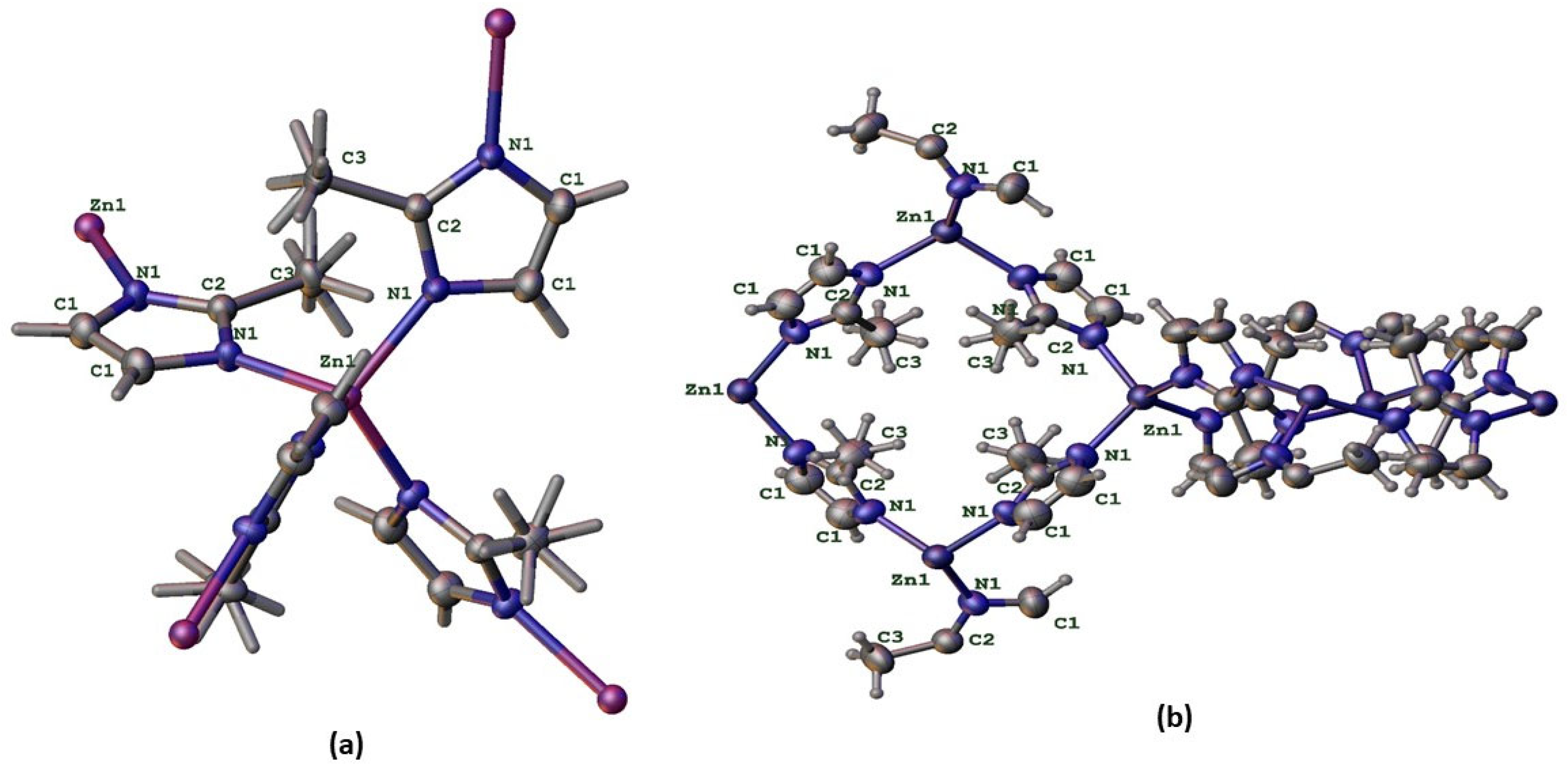
Figure 2.
Projection of the ZIF-8 Framework along Various Crystallographic Planes ((010), (001), and (011)) Highlighting the Tetrahedral Zn–Imidazolate Cages.
Figure 2.
Projection of the ZIF-8 Framework along Various Crystallographic Planes ((010), (001), and (011)) Highlighting the Tetrahedral Zn–Imidazolate Cages.

Figure 3.
Combined Electronic and Spectroscopic Characterization of ZIF-8: (a) Mulliken Atomic Charges; (b) Electrostatic Potential Map; (c) HOMO and LUMO Isosurfaces with Calculated Band Gap; (d) Simulated IR Spectrum.
Figure 3.
Combined Electronic and Spectroscopic Characterization of ZIF-8: (a) Mulliken Atomic Charges; (b) Electrostatic Potential Map; (c) HOMO and LUMO Isosurfaces with Calculated Band Gap; (d) Simulated IR Spectrum.
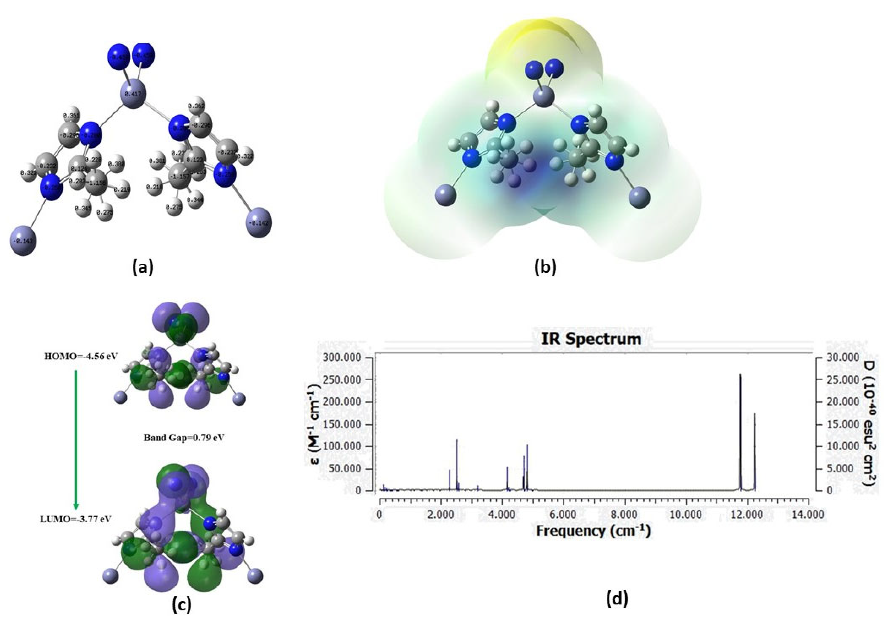
Figure 4.
ZIF- SEM micrographs of 8 particles.(a) Low-magnification view (×5 000) showing loosely bound clusters of polyhedral ZIF-8 crystals (scale bar: 2 µm).(b) Intermediate magnification (×10 000) highlighting individual polyhedral grains and surface roughness (scale bar: 1 µm).(c) High magnification (×20 000) detailing crystal facets and primary particle size (~200–300 nm) (scale bar: 400 nm).
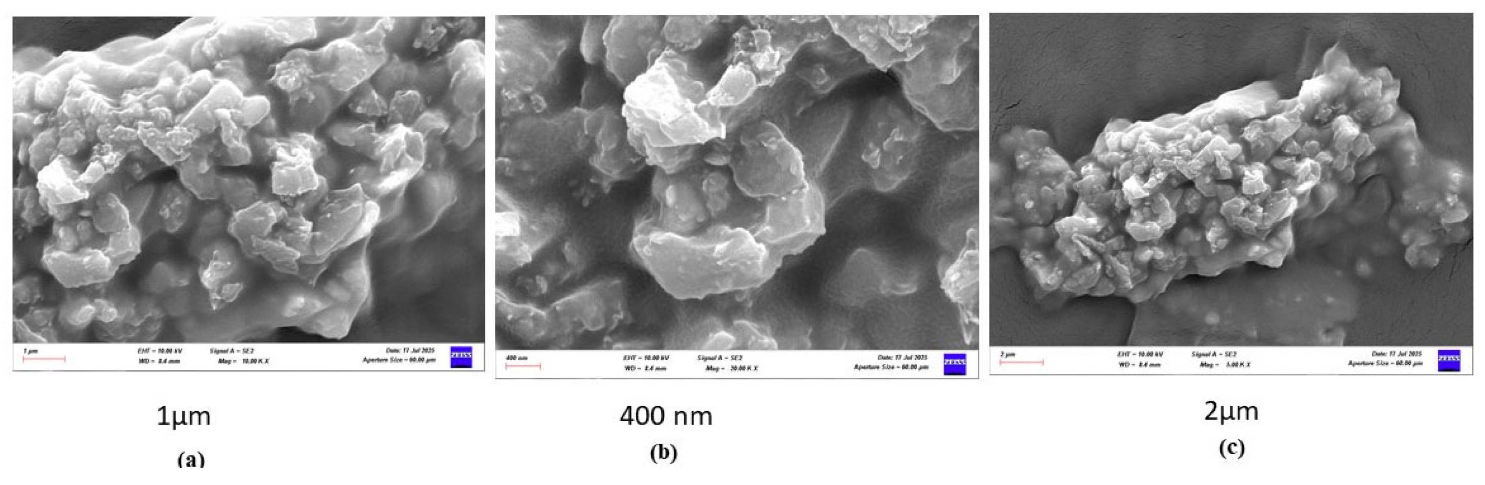
Figure 5.
EDS point spectrum (Map Sum) indicating weight fractions: C ~57.1 wt%, Zn ~20.6 wt%, O ~11.8 wt%, N ~10.5 wt%; Au peaks arise from conductive coating. C Kα₁,₂ map (red), Zn Lα₁,₂ map (orange), O Kα₁ map (blue), N Kα₁,₂ map (cyan), Au Mα₁ map (green) — each showing homogeneous distribution across the imaged area (scale bars: 500 nm).

Figure 6.
AFM analysis of copper band before and after ZIF-8 coating. AFM scans over 10 µm reveal that bare copper is smooth (±20 nm height), with minimal amplitude and uniform phase contrast. After ZIF-8 coating, nodular crystallites up to +60 nm appear, amplitude signals vary sharply over MOF facets, and phase shifts occur at cluster boundaries.
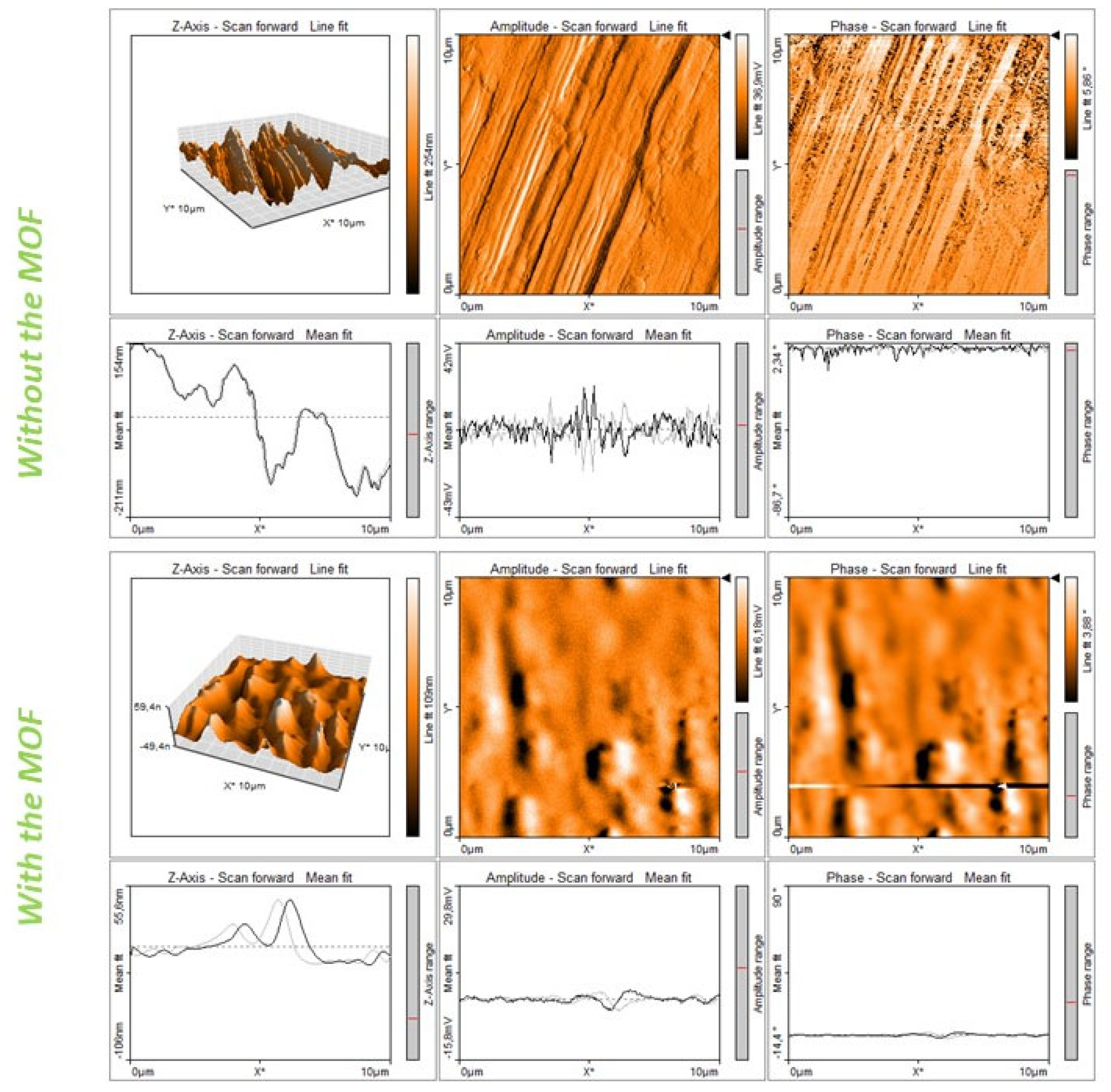
Figure 7.
Schematic Overview of ZIF-8/Polystyrene Hybrid TENG Energy Harvesting and Power Management System.
Figure 7.
Schematic Overview of ZIF-8/Polystyrene Hybrid TENG Energy Harvesting and Power Management System.
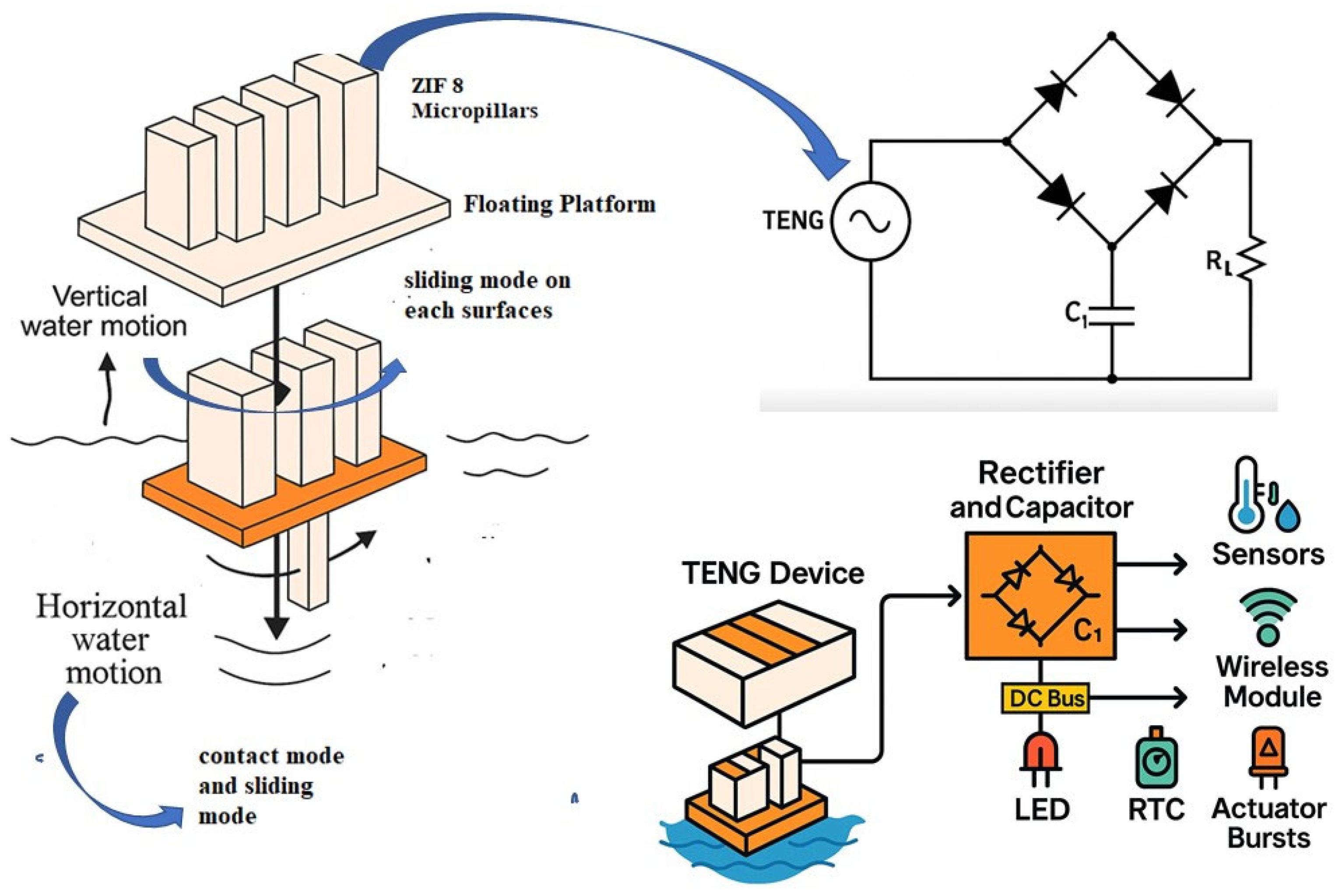
Figure 8.
Time-Series Electrical Outputs of the Hybrid-Mode TENG.
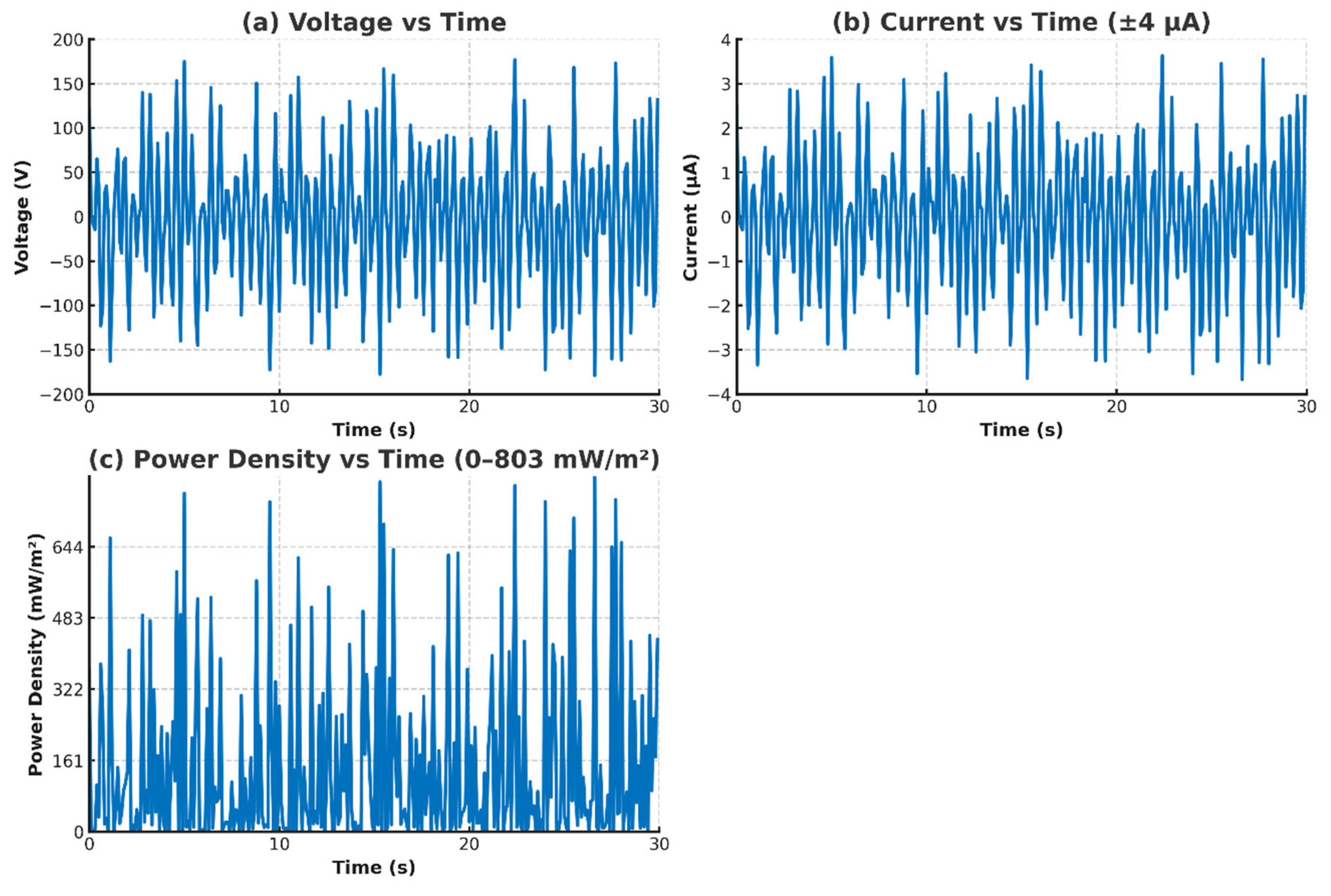
Figure 9.
Schematic illustration of ZIF-8 synthesis and spin-coated three-layer thin-film fabrication on copper tape substrate.
Figure 9.
Schematic illustration of ZIF-8 synthesis and spin-coated three-layer thin-film fabrication on copper tape substrate.
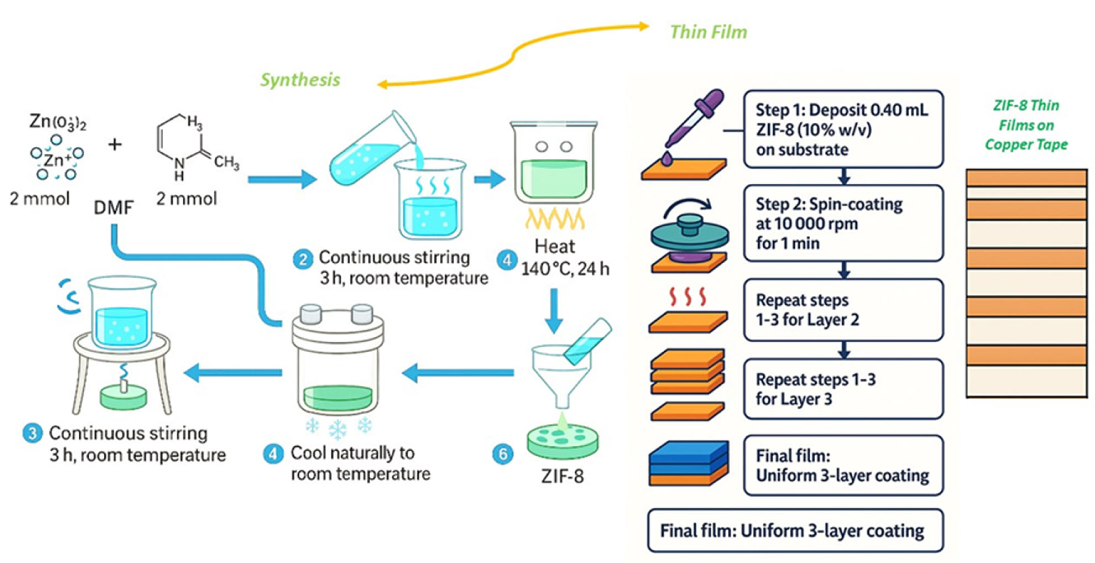
Figure 10.
Optical Micrographs of ZIF-8 Crystal Morphology.
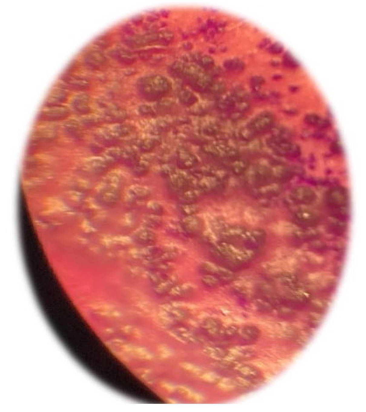
Figure 11.
Photographic Sequence of the Patterned Copper Electrode and TENG Assembly and Circuit Voltage Profiles of Copper-Strip Hybrid-Mode TENG With the MOF.
Figure 11.
Photographic Sequence of the Patterned Copper Electrode and TENG Assembly and Circuit Voltage Profiles of Copper-Strip Hybrid-Mode TENG With the MOF.
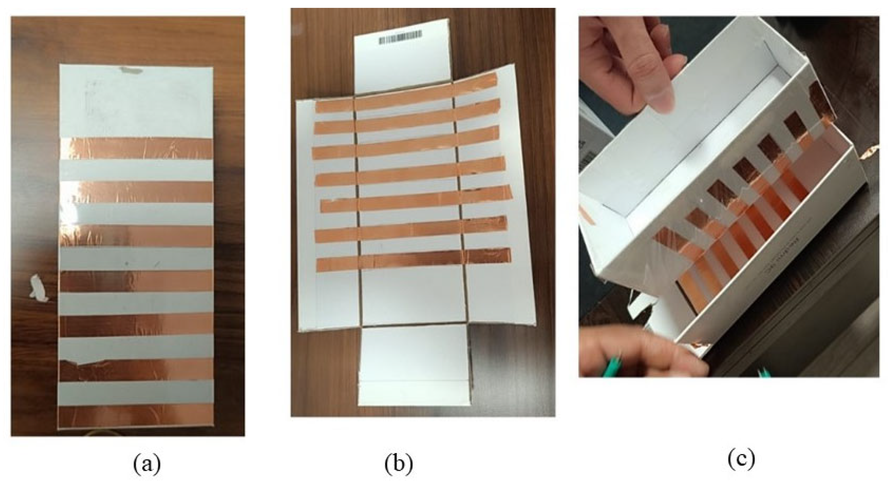
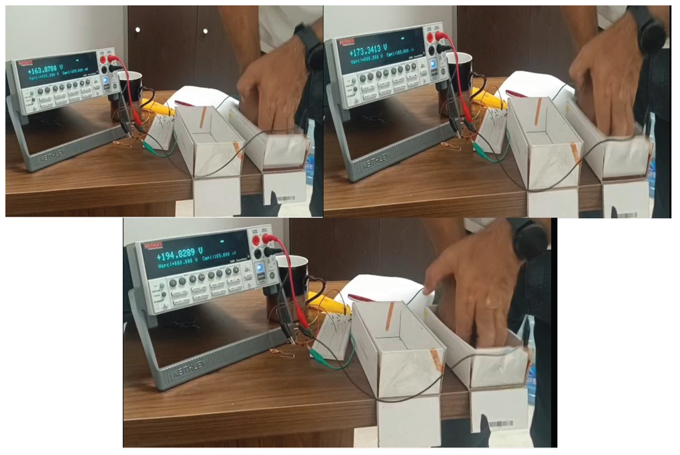
Figure 12.
Schematic illustration of a hybrid-mode triboelectric nanogenerator (TENG) for water-wave energy harvesting. The device consists of a copper top electrode and a bottom electrode coated with a ZIF-8 thin film and an intermediate polystyrene (PS) layer. Mechanical excitation by water waves generates alternating voltage and current, which are delivered through series resistive loads and a full-wave bridge rectifier to a Keithley 2450 SourceMeter via GPIB for time-resolved V–t, I–t, and P–t characterization.
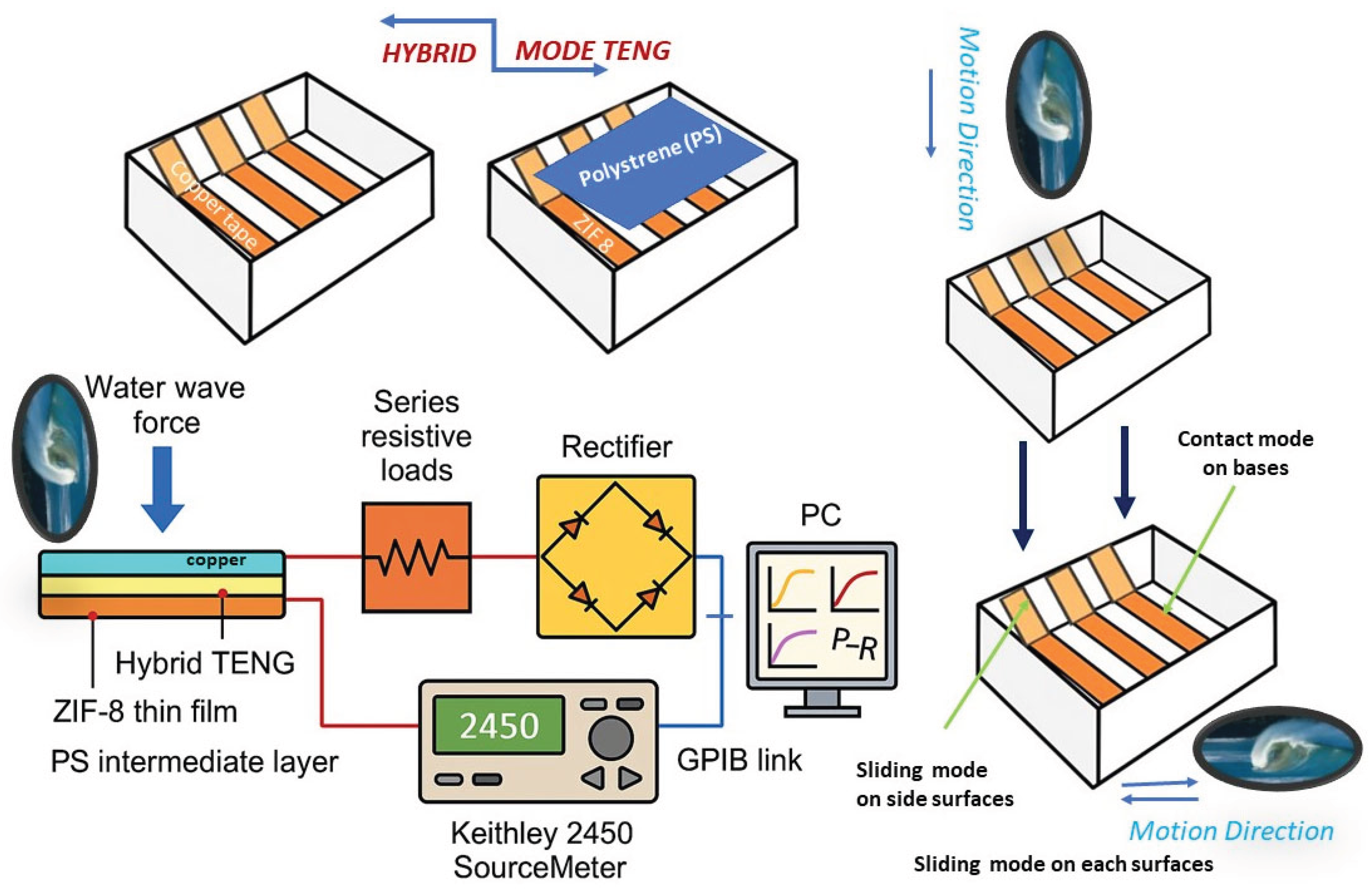

Table 1.
Selected geometrical parameters of the molecule.
| Bond Lengths (Å) | ||
|---|---|---|
| Experimental | Theoretical | |
| Zn1N1 | 2.028(4) | 2.02805 |
| Zn1N11 | 2.028(4) | 2.02868 |
| Zn1N12 | 2.028(4) | 2.02832 |
| Zn1N13 | 2.028(4) | 2.02785 |
| N1C1 | 1.347(6) | 1.34814 |
| N1C2 | 1.281(6) | 1.27991 |
| N1C14 | 1.257(11) | 1.25865 |
| C2C3 | 1.562(12) | 1.56300 |
| Bond Angles( | ||
| Experimental | Theoretical | |
| N1Zn1N11 | 109.11(11) | 102.08207 |
| N1Zn1N13 | 109.11(11) | 109.10786 |
| N1Zn1N12 | 110.2(3) | 109.12354 |
| N1Zn1N13 | 110.2(3) | 109.12780 |
| C2N1Zn1 | 129.0(4) | 129.10616 |
| C1N1Zn1 | 127.1(3) | 126.98515 |
Table 2.
Comparison of ZIF-Based MOF TENG Performance Metrics.
| MOF System | Power Density (mW·m⁻²) | Conditions / Notes | Reference |
|---|---|---|---|
| This work (236 MΩ load) | 87.3 | 2 Hz, matched load (A = 8.25 cm²) | This work |
| This work (open-circuit) | 839.1 | 2 Hz, open-circuit (A = 8.25 cm²) | This work |
| ZIF-8/MO-PPy@CelF | 33.3 | Low-frequency, PTFE counter pair | Zhang et al., “Methyl Orange-Doped Polypyrrole Promoting Growth of ZIF-8 on Cellulose Fiber for TENG,” ACS Appl. Mater. Interfaces, 2021 (PubMed) |
| ZIF-8 + MIL-100 in PAN | 18.4 | Electrospun PAN/MIL-100 composite | Liu et al., “Electrospun ZIF-8/MIL-100 Nanofiber Composites for TENGs,” J. Mater. Chem. A, 2022 |
| ZIF-8 hydrogel TENG | 3 470 | 2 wt% ZIF-8 hydrogel, matched load | Wang et al., “High-Performance Hydrogel-Based ZIF-8 TENG,” Adv. Funct. Mater., 2022 (Cell) |
| ZIF-67/PMMA | 593 | PMMA thin film | Kim et al., “ZIF-67/PMMA Composite for Enhanced TENG Output,” Nano Energy, 2023 (Cell) |
| ZIF-67 (direct growth on substrate) | 2 350 | Bare ZIF-67 layer | Li et al., “Direct Growth of ZIF-67 on Substrates for TENGs,” Chem. Eng. J., 2021 (ACS Publications) |
| ZIF-67 on cellulosic fabric | 5 | 800 MΩ load | Chen et al., “Cellulosic Fabric Coated with ZIF-67 for TENGs,” ACS Sustain. Chem. Eng., 2020 (ResearchGate) |
| MOF-modified ZnO/PAN | 800 | ZIF-8 or MIL-100 in ZnO/PAN matrix | Liu et al., “ZnO/PAN Nanocomposites with ZIFs for Triboelectric Harvesting,” Mater. Today Energy, 2023 (ResearchGate) |
Table 3.
Crystallographic details for the ZIF-8.
| Name | Molecule |
|---|---|
| Empirical formula | C8H10N4 Zn |
| Formula weight | 227.57 |
| Temperature (K) | 295(2) |
| Crystal system | cubic |
| Space group | I-43m |
|
Unit cell dimensions a (Å) b (Å) c (Å) (⁰) β (⁰) |
16.9887(2) 16.9887(2) 16.9887(2) 90 90 90 |
| Volume/(Å3) | 4903.21(17) |
| Z | 12 |
| Dcalc (g/cm-3) | 0.925 |
| Absorption coefficient (mm-1) | 1.477 |
| F (000) | 1392.0 |
| Crystal size (mm) | 0.31× 0.25 × 0.23 |
| h ranges | -21→21 |
| k range | -21→21 |
| l range | -21→21 |
| Reflections collected/unique | 5673/3182 |
| Data / restrains / parameters | 3543/967/35 |
| Goodness of fit on F2 | 1.065 |
| Final R indices [I > 2σ(I)] | R1 = 0.0338 wR2 = 0.0955 |
| R indices (all data) | R1 = 0.0352 wR2 = 0.0966 |
| Largest difference peak and hole (e Å-3) | 0.33/-0.18 |
| Flack parameter | 0.29(3) |
Disclaimer/Publisher’s Note: The statements, opinions and data contained in all publications are solely those of the individual author(s) and contributor(s) and not of MDPI and/or the editor(s). MDPI and/or the editor(s) disclaim responsibility for any injury to people or property resulting from any ideas, methods, instructions or products referred to in the content. |
© 2025 by the authors. Licensee MDPI, Basel, Switzerland. This article is an open access article distributed under the terms and conditions of the Creative Commons Attribution (CC BY) license (http://creativecommons.org/licenses/by/4.0/).
Copyright: This open access article is published under a Creative Commons CC BY 4.0 license, which permit the free download, distribution, and reuse, provided that the author and preprint are cited in any reuse.


