
Submitted:
18 July 2025
Posted:
23 July 2025
You are already at the latest version
Abstract
While synthetic biology has traditionally focused on creating or redesigning biological systems often through genetic engineering, emerging technologies, for example, implantable pacemakers with integrated piezo-electric and tribo-electric materials are beginning to enlarge the classical domain into what we call symbiotic synthetic biology. These devices permanently attached within a body, although non-living or genetically unaltered, closely mimic biological behavior by harvesting biomechanical energy and providing functions such as autonomous heart pacing. They form active interfaces with human tissues and operate as hybrid systems, similar to synthetic organs. The present paper first presents a short summary of previous in vivo studies on piezo-electric composites devoted to battery-less pacemakers and then summarizes a recent theoretical work using a damped harmonic resonance model to mimic the working of such devices. We then extend the theoretical study further to include new solutions & obtain a sum rule for the power output per cycle in such systems. Lastly, a novel proposal is made to explore the modulation of the quantum vacuum energy (Casimir effect) by periodic body movements to power pacemakers.
Keywords:
symbiotic energy harvesting
; cardiac cycle
; pacemakers
; damped resonance
; power output per cycle
; Casimir effect
I. Introduction
One of the recent innovations in the field of bioelectronic medicine is the use of implantable devices with the capability of harvesting bio-mechanical energy from cardiac motion. Such self-powered devices are expected to facilitate cardiovascular functionality in patients with compromised hearts. While such development requires the integration of the concepts of bioelectronic medicine principles with cardiovascular physiology, it is equally important to develop our quantitative predictability of the functioning of such bioelectronic device [1,2,3,4]. From a broader systems perspective, particularly within the realms of bio-hybrid and cybernetic biology, such devices can be seen as part of an expanding synthetic biology landscape that we have dubbed symbiotic synthetic biological systems. Especially when equipped with bio-sensing capabilities and real-time feedback control, they represent a new class of engineered systems that not only coexist with the body but actively participate in physiological regulation. In this sense, while not synthetic biology in the classical sense, they embody its forward-looking principles blending synthetic components with biological function in a seamless, integrated manner [5,6,7,8,9]
Cardiovascular diseases remain the primary contributor to global morbidity, with myocardial infarction, a condition triggered by restricted oxygen and nutrient delivery to cardiac tissue frequently culminating in heart attacks due to coronary artery blockages. Synthetic biology offers an emerging avenue to address this, where engineered biological systems can be harnessed to develop smart, tissue-integrating constructs or living therapeutic implants that actively sense, respond, and promote regeneration within the infarcted myocardium, offering a programmable alternative to conventional stents or static biomaterial implants [1,2,8,10].
A major limitation of implantable bioelectronic devices lies in the finite lifespan of their onboard batteries, which are prone to self-discharge and require periodic replacement. Synthetic biology offers a transformative approach by enabling the design of living or bio-hybrid systems, capable of autonomously generating energy in situ. By integrating engineered biological circuits with energy-harvesting modules, such systems can convert physiological processes such as cardiac rhythms, muscular movement, glucose metabolism, or ion gradients like the endo-cochlear potential into usable electrical energy [11,12,13,14]. These bioengineered platforms exploit electromechanical transduction strategies, such as piezoelectric and tribo-electric effects, to sustain long-term device functionality without reliance on conventional power sources[15]. Synthetic biology provides a powerful platform for reimagining energy solutions in bioelectronic systems, by designing living or semi-living systems capable of harvesting energy from within the body. Instead of relying on conventional electrochemical batteries, which are constrained by limited lifespans and require periodic recharging or replacement, engineered biological systems can be programmed to convert endogenous bio-mechanical cues such as motion, strain, or metabolic activity into electrical energy [16,17,18]. When integrated with next-generation wearable or implantable devices and connected through the Internet of Things (IoT), these bio-hybrid constructs enable a new class of self-sustaining, adaptive healthcare technologies that operate in harmony with the body’s natural rhythms and resources][19]. With the rise of bio-integrated technologies, piezoelectric nano-generators (PENGs) have gained significant attention for their ability to convert even minimal mechanical inputs into electrical signals with good efficiency. Their responsiveness to subtle strains and compatibility with miniaturized designs make them particularly suitable for next-generation biomedical devices. When combined with synthetic biology, PENG-based systems can be embedded within engineered tissues or cellular environments to create autonomous, self-powered platforms[20,21,22]. These hybrid constructs hold immense promise for powering implantable and wearable devices such as biosensors, pacemakers, neural stimulators, drug delivery modules, and regenerative scaffolds offering a shift from static electronics toward dynamic, biologically interactive systems [23,24,25,26].
In this context, our study delves into the expanding domain of symbiotic synthetic biology by investigating the potential of self-sustaining cardiac implants that operate without traditional batteries. Specifically, we focus on the design and integration of self-powered pacemakers that harness bio-mechanical energy, generated naturally through bodily functions, such as heartbeats to produce sufficient electrical output for device operation. To provide a comprehensive foundation, we begin by reviewing a series of in vivo studies that have demonstrated the effectiveness of piezoelectric and tribo-electric nano-generators in enabling battery-less pacing. Building upon this, we present experimental results from our own research group, where we developed PVDF-based composite materials incorporating and ceramics, tailored to enhance electromechanical response under physiological conditions. These materials are evaluated for their applicability in PENGs capable of supporting cardiac functions. To complement our experimental insights, we extend a theoretical model based on a forced, damped harmonic oscillator to quantitatively analyze the dynamic energy output per cardiac cycle under realistic physiological forces. Finally, we propose an exploratory concept involving the modulation of Casimir vacuum energy through periodic body motion, highlighting a radical but theoretically grounded approach to power future implantable devices. Collectively, these efforts aim to establish a robust framework for the next generation of intelligent, bio-integrated implants that exemplify the principles of symbiotic synthetic biology.
II. In Vivo Animal Studies of Battery-Less Pacemakers
Self-powered pacemakers represent an advanced class of implantable devices that generate their own energy by converting natural bodily movements like heartbeats, breathing, or blood circulation into electricity. They use piezoelectric or tribo-electric nano-generators to achieve this energy conversion, allowing them to operate without external power sources [27,28,29,30,31,32,33,34]. This approach reduces the need for battery replacements, lowers surgical risks, and ensures reliable, long-term cardiac support [35,36,37]. In the following, we summarize various attempts towards self-harvesting pacemakers that we found promising.
For example, Li et al. [38] developed a piezoelectric energy harvesting system, based on (72%) and (28%) (PMN-PT), capable of directly powering a full-function cardiac pacemaker using heartbeat energy. The device achieved high outputs up to about 20 V and 8A in series mode and about 12 V & 15A in parallel mode, exceeding previous reports. It successfully drove a commercial pacemaker and it offers adjustable output, making it suitable for various implantable devices. In another study, a multi-beam cardiac energy harvester was designed using PDMS (Polydimethylsiloxane) filled microporous P(VDF-TrFE) (poly(vinylidene fluoride-trifluoroethylene)) composite films, enhanced with 30% ZnO and 0.1% MWCNTs (Multi-walled carbon nanotubes), achieving 46 times higher voltage output than the pure polymer. Incorporating PDMS further boosted output by 105%. A compact cylindrical device was developed to mount on pacemaker leads, capturing energy from their motion by Xu et al. [39]. Single-crystalline and (PMN-PZT) harvested energy from porcine heartbeats, producing an open-circuit voltage of 17.8 V and a short-circuit current 1.74A. Its excellent biocompatibility supports its potential use in biomedical devices and wireless healthcare systems Kim et al. [40]. In another study, a flexible, implantable energy harvester using highly piezoelectric single-crystal and (PIN-PMN-PT) have been developed. The device generated a high in vivo current of 20A () from porcine heart motion, enabled by the material’s strong piezoelectric properties, a Ni-assisted exfoliation process, and a metal-insulator-metal (MIM) structure. It also functioned as a self-powered cardiac sensor, detecting heart rate changes due to drug administration. Biocompatibility tests confirmed no cytotoxic effects, highlighting its promise as a reliable power source for implantable biomedical electronics [41]. Ouyang et al. [42] developed a fully implanted symbiotic pacemaker powered by an implantable tribo-electric nano-generator, based on polytetrafluroethylene (PTFE), capable of both energy harvesting and storage. The system effectively corrected sinus arrhythmia in a large-animal model. The nano-generator produced an open-circuit voltage of 65.2 V and harvested J of energy per heartbeat exceeding the endocardial pacing threshold of J, demonstrating its potential for self-sustained cardiac pacing. A flexible piezoelectric nano-generator using PVDF nano-fibers embedded with ZnO and reduced graphene oxide (rGO) implanted near the left ventricle, harvested per heartbeat exceeding the energy required for cardiac pacing, highlighting its potential for self-powered pacemakers [43]. Hwang et al. [44] developed a high-performance flexible energy harvester using single-crystal - (PMN-PT) thin films, transferred onto a polyethylene terephthalate (PET) substrate through a mechanical Ni exfoliation process. The device converted bio-mechanical motion into electrical energy, producing up to A and 8.2 V. Finite element analysis (FEA) confirmed energy generation from stress-induced bending. When implanted in a rat heart, the flexible PMN-PT harvester enabled real-time functional electrical stimulation, showing promise as a sustainable power source for recharging batteries and powering artificial cardiac pacemakers. Zhang et al. [45] developed a self-powered pacemaker using an all-in-one piezoelectric nano-generator (A-PENG) that harvests cardiac bio-mechanical energy to enable effective pacing of the myocardium and conduction system. The A-PENG features strong stretchability, waterproofing, and biocompatibility, with enhanced electrical output achieved by optimizing piezoelectric particle distribution. In a canine model, it successfully stimulated the right atrium, left ventricle, and His bundle, highlighting its potential as a multifunctional, self-powered cardiac therapy device. Xie et al. [46] designed and tested a self-powered cardiac pacemaker based on PMN-PT that harnesses piezoelectric vibration energy from the heart’s natural motion. The system uses an implanted piezoelectric energy collector to convert kinetic energy into electricity, which then drives the pacemaker to deliver epicardial stimulation. In vivo tests on rats showed a peak output current of 54 nA and voltage of 3.2 mV immediately after implantation, with stable operation over 12 weeks. Although, output gradually decreased over time, it remained sufficient for pacing.
Energy harvesting through arterial wall deformation using appropriately inserted magnets that cause magneto hydrodynamic (MHD) effects during pressure variations in contraction & expansion phases, has been exploited by the Bern/Zurich group [47]. The cyclic expansion and contraction of the arteries is used to move a highly electrically conductive fluid in a compartment outside an artery. MHD energy is harvested both in the systole & the diastole part of the pressure cycle and their setup is reminiscent of a hydraulic piston as the fluid moves back and forth in the channels, an alternate current & voltage is set up. One of the theoretical tools used to model their results is a damped harmonic oscillator that is the leit motif of our paper. The power output per cycle obtained through this model reaches 65Watts.
A rather different approach has been followed by Haeberlin et al. who claim to have invented and successfully operated the first battery-less solar powered cardiac pacemaker [48]. To overcome the low power output afflicting other attempts at battery-less pacemaker designs, the Bern group used a energy gathering solar module. The energy was stored in a Farad capacitor. The group used the good skin penetrance of infrared light to harness a significant fraction of incident light by a subcutaneous solar module even indoors. They also developed an energy buffer to be used during darkness.
In their acute animal study, the pacemaker prototype was installed at a depth of mm in the right lateral neck of a 60 Kg female domestic pig (under anesthesia). During irradiation (mimicking full direct sunlight) of the module-covering skin layer, they measured an output power of , to be compared with a typical pacemaker power of about . For further studies with different shades of sunlight and other technical details, see [48].
In the next Sec.(III) we describe electrical response results obtained by our experimental group from piezo-electric composites constructed for self-harvesting devices (called PENG).
III. Electrical Response Results from Our Group’s Piezo-Electric Composite Materials
Figure 1.
Voltage pattern of piezoelectric nano-generators under (a) arm bending, (b) normal bending, and (c) flexing motions. [Attenuation ratio: 100:1]
Figure 1.
Voltage pattern of piezoelectric nano-generators under (a) arm bending, (b) normal bending, and (c) flexing motions. [Attenuation ratio: 100:1]
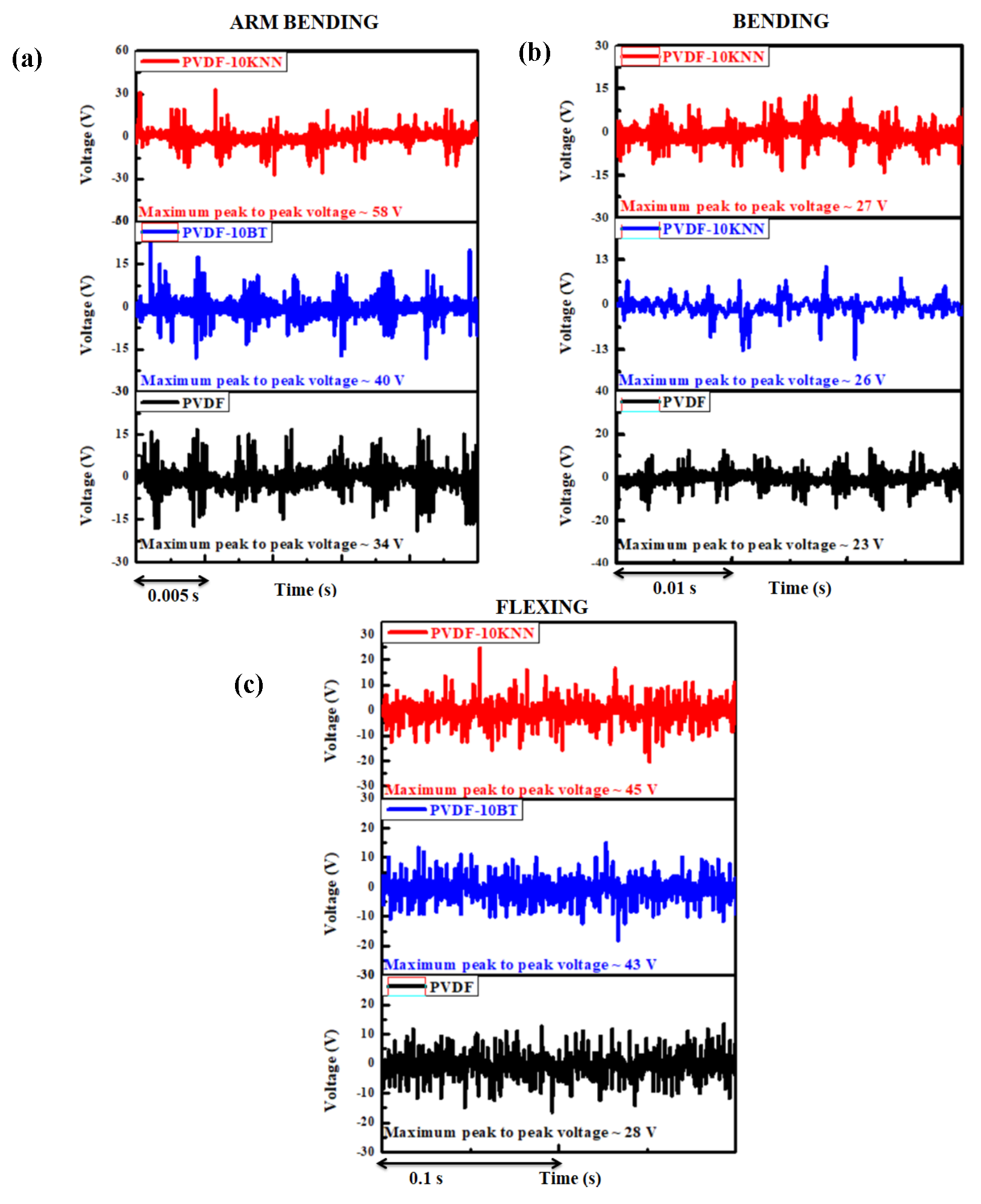
As stated earlier, self-powered pacemakers represent a groundbreaking development in biomedical technology, designed to eliminate reliance on traditional batteries by utilizing the body’s inherent mechanical movements as a source of energy. A key innovation driving this progress is the PENG, which converts bio-mechanical motions into electrical energy through the piezoelectric effect. When incorporated into implantable cardiac devices, PENGs provide a reliable and long-lasting power supply, potentially minimizing the need for repeated surgical interventions due to battery exhaustion.
Piezoelectric biomaterials produce electrical charges when subjected to mechanical stress. In the context of pacemakers, this stress is naturally induced by bodily activities such as the rhythmic beating of the heart. Widely used piezoelectric materials include (BT), and more environmentally friendly options like K0.5Nb0.5Nb (KNN) and polyvinylidene fluoride (PVDF)-based composites. These materials are favored for their strong piezoelectric response, mechanical flexibility, and compatibility with biological tissues.
On behalf of the above, we have developed self-powered PENGs using PVDF and its composites (PVDF-10 wt%BT, PVDF-10 wt%KNN) to analyze their electrical characteristics in terms of voltage for their applicability in self-powered pacemakers, which require around 3 V for their operation [44].
The BT ceramic was synthesized via a conventional solid-state reaction route. Precisely weighed stoichiometric amounts of (Reidel) and (Loba Chemie) were ball-milled in ethanol for 6 hours, followed by drying and calcination at 1100oC for 8 hours. In a similar manner, the KNN ceramic was prepared using (Sigma Aldrich), (Sigma Aldrich), and (Otto) as starting materials.
These precursors were accurately proportioned, mixed, and subjected to ball milling in ethanol for 24 hours, after which the powder was calcined at 910o C for 10 hours.
PVDF (SOLEF 6008; , density = ) was dissolved in dimethyl form-amide (DMF, SRL) by stirring at 80 degrees C, until a clear solution was formed. Separately, 10 wt% of BT and 10 wt% of KNN were each dispersed in DMF, stirred at 60 degrees C, and then ultrasonicated to obtain uniform dispersions. These ceramic dispersions were gradually added to the PVDF solution and stirred at 80 degrees C until a homogenous mixture was achieved. The resulting solution was cast into a petri dish and dried overnight at 60 degrees C in a vacuum oven. The dried films were then processed using hot compression molding to obtain thin films with a thickness of approximately m. Composite samples of PVDF, PVDF-10BT and PVDF-10KNN were cut into square pieces measuring . A conductive silver coating was applied to both surfaces of each sample, and silver foil was affixed to facilitate charge collection. Wires were then connected to the electrodes. The entire assembly was encapsulated using poly(dimethylsiloxane) (PDMS, Sylgard 184), prepared by mixing the elastomer base and curing agent in a 10:1 (vol/vol) ratio. The encapsulated devices were then placed in a vacuum oven and cured at 55 degrees C for 2 hours.
The voltage of the prepared devices was measured under arm bending, normal bending, and flexing motions using a digital oscilloscope [Attenuation ratio 100:1, Keysight InfiniiVision DSOX2014A]. The maximum peak-to-peak voltage produced by PVDF was 34 V (arm bending), 23 V (normal bending), and 28 V (flexing). The maximum peak-to-peak voltage produced by PVDF was 34 V (arm bending), 23 V (normal bending), and 28 V (flexing). The maximum peak-to-peak voltage produced by PVDF-10KNN was 58 V (arm bending), 27 V (normal bending), and 45 V (flexing motions) [Fig. 1].
IV. Previous Analytic Work on a Forced, Damped Resonant Model for Self-Energy Harvesting Pacemakers
In this section, we first summarize our previous theoretical model for a pacemaker and discuss salient results obtained therein[37].
A normal resting adult heart performs () beats per minute. This translates into a 4-part cardiac cycle time period sec per beat and thus a beat frequency per second. The angular frequency sometimes also called the natural frequency of the heart is defined as , that normally lies between () radians/sec. Of course, there is an external force acting on the heart (provided by blood impinging upon it). We idealized our pacemaker dynamics to follow that of a forced harmonic oscillator in steps of increasing complexity.
The equation of motion for the displacement -from its equilibrium position- of an externally forced (ideal) harmonic oscillator with mass M and force constant k can be derived through the Lagrangian :
The above would be true in the vacuum that is devoid of a medium. Such is obviously not the case here. For example, the viscosity of circulating blood in the system makes the system dissipative (non-conservative). This is theoretically described by augmenting the above Lagrangian with a Raleigh function , that is quadratic in the velocity (): (See, for example, references [49] & [50])
In reference [37], we considered the dynamics described by the above linear differential equation for the explicit case of the external force being limited to a sum of sinusoidal force terms with various frequencies
Here is the displacement from the equilibrium position and is the corresponding external force acting on the ith coordinate; M is the effective mass of the pacemaker; is the effective resistance -in inverse time units- physically produced by blood impacting the system
Since the differential equation is linear in , we can solve it in the complex form (and then take the real part). Now, as a function of time t, consider the canonical time dependence . So that, for complex , the equation reads
and we seek steady state solutions for that have the same time dependence as does the force term apart from it being phase shifted by
Since is by hypothesis real, we have
So that
The mean or average displacement (over 1-cycle) is defined as
is independent of the phase . Otherwise said, the mean displacement does not depend upon the boundary condition i.e., the choice of .
In [6], the behavior of the mean displacement as a function of the ratio () can be found. Also, studied there is the change in the mean displacement and the energetics of the system as the mass parameter M is varied.
V. Power Dissipation per Cycle
Now let us summarize the energy and power considerations and a sum rule for mean power per cycle over all frequencies.
Figure 2.
Plot of vs. y where . See, Eqs.(14 et sec).
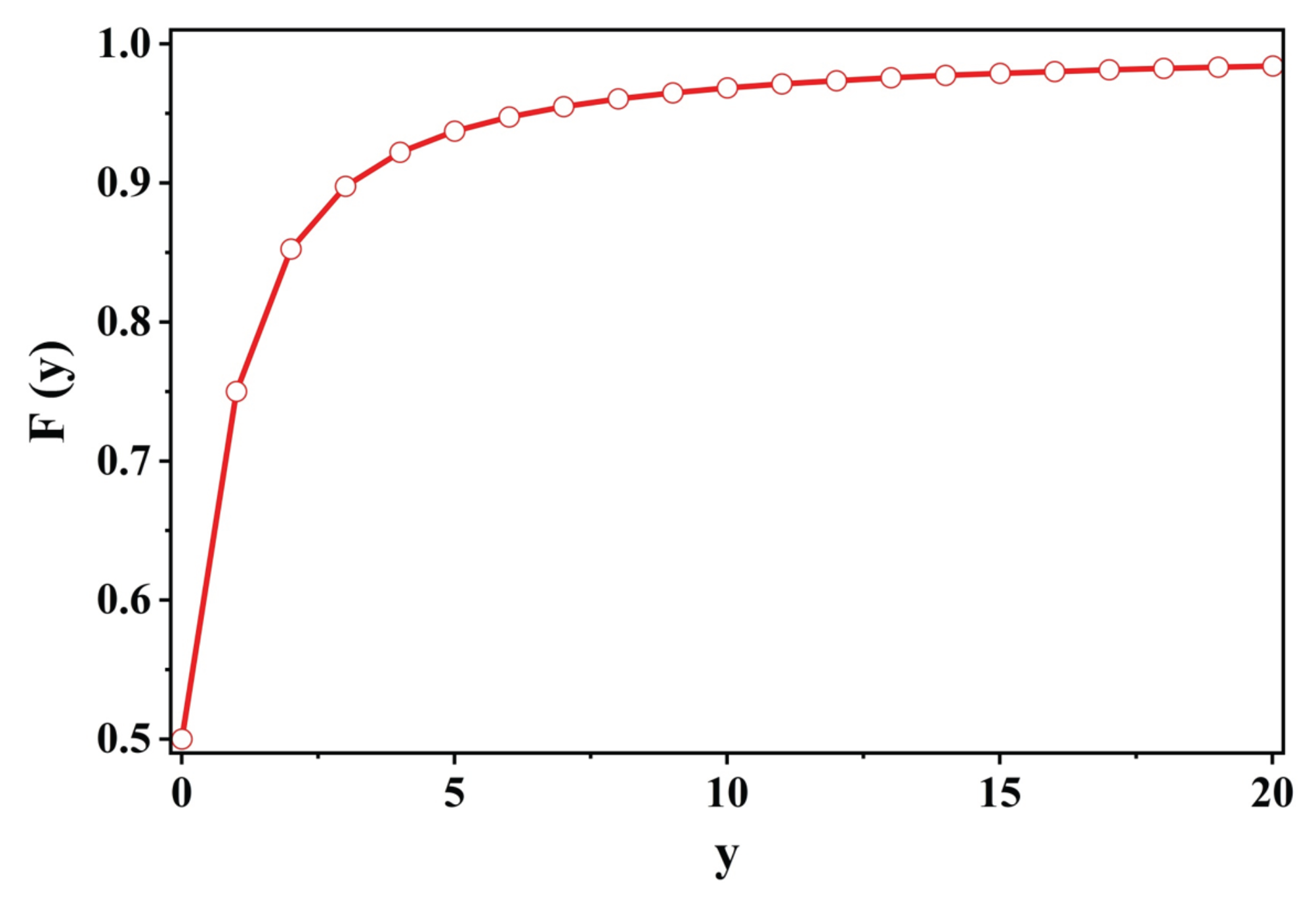
In steady motion, for displacements of the system obeying Eq.(7), the energy of the system is conserved. The energy is continually being absorbed by the system from the source of the external force and then is dissipated by the system: vedi page(79), section(26) of [49].
Consider one degree of freedom and write the energy function and relate its energy loss per unit time to the Raleigh dissipation function . For our choice , the damped harmonic oscillator equation of motion is as given in Eq.(3). The power dissipated is calculated through the generalized force equations:
Thus, the power loss is twice the Raleigh dissipative function (which is why ). In particular, using Eq.(7), we have for the power dissipated at the external frequency ()
The mean power absorbed per cycle at the frequency
To exhibit the Lorentzian power distribution near the resonance, as usual, we expand :
The maximum of this mean power is at and is proportional to ():
The full-width of this bell shaped curve (as a function of ) is (); that is the ratio Eq.(13(ii)) is half its maximum value () as to [vedi Figure(31) in [49].
As the maximum of the mean power (per cycle) at a given external frequency () is inversely proportional to () whereas its width is proportional to (), the integral of the mean power over external frequencies is independent of (). Explicitly,
If we extend the lower limit to ,
The solution of Eq.(d13) is independent of () as well as (). This is a sum rule on all external frequencies, which in its Fourier transform space (that is time), basically probes the system at . This implies that the system has not had enough time for either the natural frequency or the dissipative frequency to play any role. The only parameters that enter the sum rule are the force F at & the inertial mass (M)[50].
Now we can estimate analytically the fractional contribution to the total dissipated power per cycle as given in Eq.(14) for various ratios of versus . Fortunately, is only a function of the scaled dimensionless variable (of course, after all the various approximations along the way) and we have
Thus, we were able to show that the power integrated (over all external frequencies) per cycle for is not infinitesimal but quite substantial. This result is in sharp contrast to the conclusions derived from a naive perusal of the variations of the mean displacement. In it, there is no hint of a bell shaped curve for :
and we see that the mean displacement is a monotonically decreasing function of & .
In fact, the true behavior of mean dissipated power is quite different as it depends upon the Raleigh function thus, upon squares of velocities as discussed above.
Our result may appear non-intuitive for a very good reason. If one sets at the outset, namely a resonance with no friction at all, one has the unphysical result that the mean displacement is infinite for . Also, the phase lag jumps discontinuously from to zero. Hence, for physically sensible results near resonance one needs the Raleigh term with . This makes the power finite and the phase continuous but then the limit must be taken with care. It is formally coded in a Dirac delta function. Explicitly, we have the standard result
Insufficient care in handling this peculiarity can lead to errors.
As we shall see in a later section, a particular ratio is of interest in a model by Bahramali et al [51] that focuses on self-regulation (of the contraction part) of the heart based on an analysis of the QRS sequence in ECG. We find the integrated power for this case, using Eq.(16), to be
VI. Further Studies of Power Outputs per Cycle and Extension of the Previous Theoretical Model
In the previous section (V), we limited our analysis of the power output per cycle (as well as our derivation a sum rule for the integrated power over all frequencies) to be constrained by the “Lorentzian” approximation, see Eqs.(12) et sec, that is rigorously valid for small . But as we need to employ , to approximately take into account the viscosity of blood, we need to generalize these previous results to be valid in the larger interval of . Let us rewrite the exact Eq.(11), calling & , for notational simplicity:
and the maximum power (per cycle) given by
that is (i) independent of , and (ii) inversely proportional to , just as in the Lorentzian approximation. Thus, we have
in Eq.(22) being dimensionless, depends on two variables only (rather than three) which we shall choose to be and , so that
We next compute the full width at half maximum, i.e., the values () at which . Using Eq.(23), it is readily established that
exactly as was found earlier in the Lorentzian approximation in Sec(V). Thus, the power per cycle normalized to its maximum value 1 indeed goes down to half its value for . It is interesting to observe that while both () have order corrections, their difference () retains its pristine Lorentzian value ().
VII. EM Oscillators in the Body
With electrical signals propagating in the body through narrow orifices, it is not a bad approximation to model them as LRC circuits written (in SI units) as
where Q is the charge & is the external applied voltage; are constant inductance, resistance and capacitance respectively. is the instantaneous current in the circuit. If we divide Eq.(25) by L and compare it to Eq.(1) divided by M, we have the following correspondance
so that we have the dictionary
through which we can freely transcribe all the results derived earlier in Sec.(V). For example, we can calculate the mean charge displaced per cycle () defined as usual as rms charge displacement. For an initial sinusoidal external voltage , with mean voltage (), it is given by (vedi, Eqs.(8 & 27):
Similarly, the mean current per cycle can be shown to be given by
and the mean power per cycle to be
For completeness, we also quote the integrated power over all frequencies
reinforcing the interpretation that the inductance L plays a role in (stable oscillating) EM circuits quite similar to that of mass M for a (stable oscillating) mechanical system. When , there are no dynamical EM waves, there are simply (charging or discharging) static electrical systems. Idem for a mechanical system in the formal limit as the mass .
Of course, on a practical basis there is a huge fundamental difference between a dynamical EM system and a mechanical system. It is much easier to vary EM parameters, the effective () by designing appropriate circuits and even miniaturizing them; much harder to do with mechanical circuits. Nature uses both in a variety of ways. For example, the heart itself can be considered an (excellent) periodic material oscillator, whereas the progenitors of the heart’s activity are fine electrical pulses of much smaller time periods. Also, there are mixed forms arising from naturally occurring (or, man made) piezo-electric and visco-electric materials. Some of these are of direct concern in this paper.
VIII. Self-Regulation of the Heart
Before embarking upon the logistics of battery-less devices for the heart, let us briefly note what is known about the Nature’s way of self-regulating the heart that can reach an accuracy of about one part in a billion (not missing a beat in a lifetime). Luckily, an artificial pacemaker’s job is not the well-nigh impossible task of reproducing the entire gamut of natural self regulation of the heart. Rather, it is limited to modulating some misbehaving heart-beats (hopefully requiring corrections only sporadically).
The quality of self-regulation of a heart is externally monitored through electronic recordings provided by various devices (ECG, EKG) through appropriately placed surface electrodes on the body of a subject. A study of the pattern of deviations from standard P,Q,R,S,T....signals, inform a clinician about the nature and the extent of lacuna in electrical free flow. Time span of these signals ranges roughly between ( seconds) that is much shorter than a heart beat ( seconds). Translated into the frequency domain, the observed electrical signals are at much higher frequencies than the beat frequency. To study the finer details of the electrical signals, a certain splicing of the QRS signal, that covers the time period while a heart is contracting, was made in reference [51]. They argued that their chosen segment() can be considered as a solitary wave and thereafter showed that its characteristics could be matched to that of an underdamped harmonic oscillator. As it is closely related to the subject matter at hand, let us consider its harmonic oscillator aspect in some detail.
In our notation, the mean response (over a cycle), for example for the mean displacement () of a damped harmonic oscillator with a resistance term and a natural frequency , when probed at an external frequency , is described through Eqs.(6, 7) to be
For a constant time-independent force F (that is, formally the response at zero external frequency ), , so that we have the following input-output relation:
In Feedback Control theory parlance, is the transfer function [52], pertinent to our case of a driven, damped harmonic oscillator. Notice that it is normalized so that when the external force is a constant (or, very nearly a constant in the time period of observation) so that the limit can be applied, the transfer function identically becomes unity, independent of the natural frequency as well as the frictional frequency .
Our transfer function only depends on two variables [ and ] and is independent of the overall scale, . For a fixed non-zero zeta (), has a maximum at
[53]
As stated earlier, an extremely intriguing connection has been discovered in reference[51] between an empirical transfer function and an empirical Bode diagram , both constructed by them after a cleverly spliced () segment and comparing it to that of a driven, damped harmonic oscillator as given in Eq.(34 & 35). Matching the empirical data with the theoretical, see their Figs.(8,9), they obtained the following values for the oscillator parameters:
The lifetime of such an underdamped oscillator is traditionally considered to be given by the inverse of the full-width at half-maximum of the resonance peak. If we accept this interpretation, then we might conclude that for our considered subsystem:
IX. More on Damped Oscillators with Transients and Various Harmonic Inputs
With an eye towards exploiting the periodic pressure pulses as the engine for running our battery-less pacemaker, let us complete our treatment of the damped harmonic oscillator in three respects. As we need to follow the system from the inception of the cycle to its end, we need to include the homogeneous (or, as commonly called transient solutions) as well as obtain explicit solutions that include a large number of harmonics to realistically portray the somewhat complicated spectrum of pressure pulses, along with imposing proper boundary conditions. If we consider a uniform cylindrical cavity of radius r through which our fluid flows, then the pressure can be related to the overall force
and we shall model in terms of a large (but finite number of harmonic) components, with the boundary condition that
In ref.[47], is used; but by contrast, we shall not be employing magnets whose lever arm displacements will endow the needed power to a pacemaker. Thus, our equation of motion reads
The general solution for the spatial displacement satisfying Eq.(40) reads
Expanding the inhomogeneous displacement in terms of the harmonics , the solution reads
The boundary conditions that both the initial displacement and the initial velocity be zero: & fix the coefficients :
X. Can a Pacemaker be Powered by Modulating the Casimir Vacuum Energy via Motions of the Heart?
In this section, we would like to direct the attention of our readers that with the advent of synthetic nanopores (of radii nanometers) and a radius nm for carbon nanotubes, a novel perspective is opening in biology: we can exploit the energy of the quantum vacuum (the Casimir effect) by modulating it through the motion of the heart (or, movement of any other organ in principle).
Similar ideas had been explored in earlier papers [54,55], and were employed to explain that despite red blood cells carrying negative charges, under certain conditions they stick together to form cylindrical stacks, or rouleaux [56]. This is a practical example of what would later be called stiction in microelectromechanical systems (MEMS). In reference [57], anharmonic Casimir oscillator (ACO) device was proposed for a MEMS system. Their idea for a MEMS device was to attach a spring to one side of a moveable plate and find bi-stability of the plate through the competing dynamics of elastic energy versus the Casimir energy provided by a fixed nearby plate placed on the other side.
However, it is the advance from micro to nano manufacturing that the true potential of the quantum vacuum in biology emerges. We show below that the magnitude of energy/area as well as the power that may be generated is in the range of what is needed to run self-harvesting devices such as a pacemaker and apparently it can be modulated and thus harnessed.
The (attractive) Casimir energy (, of the quantum vacuum) between the two parallel (ideal) capacitor plates each of cross-sectional area () and a distance (d) apart, filled with a dielectric () fluid in between reads[54,55]:
It is worthy of note that while the Casimir energy (per unit area) arises from the quantum electro-dynamics (QED) vacuum, it is independent of the charge. We could have used dimensional analysis to obtain it to be proportional to (). What is surprising is that (i) it is finite, that (ii) we can compute its sign, it is attractive (for this geometry) and (iii) compute its exact magnitude: Casimir’s tour de force.
Of course, for a fixed distance (d) between the capacitor plates, the Casimir energy is static and does not do anything; a movement () is necessary to make a resulting change in energy () that can be made measurable (and hopefully, if substantial, even useful).
If the positional change () has been triggered by the movement of the heart with a natural frequency (), we can infer that the resulting Casimir power density () would be given by
more than two orders of magnitude larger than the power/area of a typical pacemaker. Of course, the dependence, makes the Casimir power very sensitive to d. For example, for , its value reduces to about (), only twice the power density of a standard pacemaker.
We can also compute the Casimir pressure (defined as ) for our capacitor
that is quite large, about Pascal, for a plate separation. On the other hand, given its () decrease, by the time , it is down to about half the level of the diastolic arterial pressure pulse ():
So far, we have only considered charge neutral nanopores. On the other hand, in practice, nanopores typically have a surface charge of the order of . This is not an accident as we shall see in the following. Endowing our nanopore with a surface charge density (), our earlier Casimir energy density Eqn.(44) gets supplemented by the repulsive Coulomb energy density given by
Hence, the total energy density for the repulsive case reads:
and the system will be bound () only for small d given by
To obtain a feeling for the order of magnitudes, let us consider (i) our nanopore filled with water, & (ii) an expected charge density . Normalizing to these values, we find
Given the very weak dependence on () [typically ; On the other hand, common synthetic pores made of silicon dioxide have () or, silicon nitride (). See, [58] & decreasing as , it is reasonable to infer that most such structures with a transverse size nm would stay bound, due to the quantum vacuum energy fluctuations. Finally, we may write Eq.(50) as
Having established the needed order of magnitudes (proof of concept) for energies & power required to propel self sustaining devices, we shall postpone to future work the design of a prototype based on the Casimir energy modulations discussed here.
As Eqs.(50, 53) show, the smaller the transverse size (d) becomes [for fixed charge density () & the permeability ()], the more bound the system since the (attractive) Casimir contribution increases. However, transcending applications of Casimir energy devices for self harvesting purposes, there is a general notion of stability of (charged) nano-pores and other similar devices, brought about by the vacuum energy (& pressure) that needs to be investigated. As the vacuum pressure, on dimensional grounds goes as [], for sufficiently small (d & ), it may become large enough to jeopardize the stability of the system (Instability in preparations of lipid membranes are well documented [59]).
From the point of view of what is being proposed here, evidence from (i) negatively charged blood cells forming rouleaux; (ii) common occurance of stiction in MEMS devices and (iii)instability in preparations of lipid membranes are all precursors of even larger (vacuum) Casimir effects on systems as the physical dimensions of the devices become even smaller.
XI. Conclusions and Future Outlook
After a mini survey of some previous attempts at self harvesting devices, primarily to gather information about the level of energy density reached in each proposal, we presented a description of our own piezo-electric composite materials for future PENG devices. Then, we devoted the main body of the paper to refining theoretical results for the mean values of displacement, velocity and power per cycle for a generic damped harmonic oscillator used for modeling the mechanical system. As mentioned in the Introduction, it is important to develop a quantitative predictability of the functioning of any proposed self harvesting device.
Similarly, the electrical activity (in thin arteries for example) can be considered in a lumped circuit () model through which we can not only describe electric pulses but also superpositions of periodic electrical motions quite satisfactorily. The model allows one to include magnetic field effects as well as thus justifying the nomenclature of an electro-magnetic (EM) theory. Moreover, the dynamics of the lumped RLC circuit model can be mapped into the dynamics of the mechanical damped harmonic oscillator model both possessing similar resonant behaviors. In particular, the complex EM impedance (Z) has an exact analogue in the mechanical impedance function denoted by D in Secs.(IV) et sec. and through which mechanical and electrical powers are computed. This allowed us to exhibit a sum rule (by integrating over the external frequency) for the mechanical and the electrical power and thereby deduce a direct correspondence between the mechanical mass parameter (M) and the EM inductance parameter (L).
We also briefly touched upon the issue of the natural self regulation of the heart in Sec(VIII), as manifested by the electrical ECG signals for example. We find that a previously constructed gold standard ECG signal by Bahramali et al. [51] finds its natural habitat in our formulation.
In Sec.(V), we presented arguments about quantum vacuum energy fluctuations (the Casimir effect) becoming sizable for example for nano-pores of dimensions () nm and of low electric permeability (). The level of energy densities & power outputs from modulations of the Casimir energy through body rhythms seem encouraging for their use in replacing batteries in future pacemakers for example.
However, much work remains to be done towards understanding fundamental stability issues before arriving at designing a prototype of a vacuum-self-energy harvesting pacemaker that would herald a quintessential example of symbiotic synthetic biology.
References
- B. Basu, Biomaterials Science and Tissue Engineering: Principles and Methods, (2017) Cambridge University Press, Cambridge, UK.
- B. Basu, Biomaterials Science and Implants: Status, Challenges and Recommendations, Springer Nature, Singapore (2020).
- A. Panda and B. Basu, Biomaterials-based bioengineering strategies for bioelectronic medicine, Mater. Sci. Eng. R Rep., 146 (2021) 100630. [CrossRef]
- G. Thrivikraman, S. Boda and B. Basu, Unraveling the mechanistic effects of electric field simulation towards directing stem cell fate and function: A tissue engineering perspective, Biomaterials, 150 (2018) 60. [CrossRef]
- A. Dubey, A. Mukhopadhyay, B. Basu, Interdisciplinary Engineering Sciences: Concepts and Applications to Materials Science, CRC Press, Boca Raton USA (2020).
- K. Das, U. Kesarwani, R. Prakash, P. Maiti, O. Shankar, A. Dubey, Piezoelectric catalyst BaTiO3 and K0. 5Na0. 5NbO3 induced cellular and antibacterial response in poly (vinylidene fluoride) for self-powered implants for orthopedic applications, Catalysis Today, 452 (2025) 115255. [CrossRef]
- U. Kesarwani, A. Dubey, Cytocompatibility and osteogenic response of 1-and 2-dimensional (D) nanostructured hydroxyapatite: Influence of surface chemistry, ion release and hydrophilicity,, Inorganic Chemistry Communications, 173 (2025) 113824. [CrossRef]
- P. Tripathi, A. Dubey, Role of Piezoelectricity in Disease Diagnosis and Treatment: A Review, ACS Biomaterials Science & Engineering, 10(10) (2024) 6061. [CrossRef]
- U. Kesarwani, B. Basu, A. Dubey, 1-and 2-dimensional (1D/2D) hydroxyapatite nanocrystals: A deep insight into synthesis strategies and multidimensional applications, Applied Materials Today, 36 (2024) 102062. [CrossRef]
- D. Khare, B. Basu, A. Dubey, Electrical stimulation and piezoelectric biomaterials for bone tissue engineering applications, Biomaterials, 258 (2020) 120280. [CrossRef]
- C. Dagdeviren, Y. Su, P. Joe, R. Yona, Y. Liu, Y. Kim, Y. Huang, A. Damadoran, J. Xia, L. Martin, Y. Huang, J. Rogers, Conformable amplified lead zirconate titanate sensors with enhanced piezoelectric response for cutaneous pressure monitoring, Nature Communications, 5(1) (2014) 4496. [CrossRef]
- H. Goto, T. Sugiura, Y. Harada, T. Kazui, Feasibility of using the automatic generating system for quartz watches as a leadless pacemaker power source, Med Biol Eng Comput, 37(3) (1999) 377. [CrossRef]
- A. Zurbuchen, A. Haeberlin, L. Bereuter, A. Pfenniger, S. Bosshard, M. Kernen, P. Heinisch, J. Fuhrer, R. Vogel, Endocardial Energy Harvesting by Electromagnetic Induction, IEEE Trans Biomed Eng, 65(2) (2018) 424. [CrossRef]
- Q. Zheng, B. Shi, F. Fan, X. Wang, L. Yan, W. Yuan, S. Wang, H. Liu, Z. Li, Z. Wang, In Vivo Powering of Pacemaker by Breathing-Driven Implanted Triboelectric Nanogenerator, Advanced Materials, 26(33) (2014) 5851. [CrossRef]
- C. Dagdeviren, B. Yang, Y. Su, P. Tran, P. Joe, E. Anderson, J. Xia, V. Doraiswamy, B. Dehdashti, X. Feng, B. Lu, R. Poston, Z. Khalpey, R. Ghaffari, Y. Huang, M. Slepian, J. Rogers, Conformal piezoelectric energy harvesting and storage from motions of the heart, l ung, and diaphragm, Proc Natl Acad Sci U S A, 111(5) (2014) 1927. [CrossRef]
- N. Sezer, M. Koç, A comprehensive review on the state-of-the-art of piezoelectric energy harvesting, Nano Energy, 80 (2021) 105567. [CrossRef]
- F. Ali, W. Raza, X. Li, H. Gul, K. Kim, Piezoelectric energy harvesters for biomedical applications, Nano Energy, 57 (2019) 879. [CrossRef]
- M. Wood, K. Ellenbogen, Cardiac Pacemakers From the Patient’s Perspective,, Circulation, 105(18) (2002) 2136. [CrossRef]
- M. Wilhelm, C. Schmid, D. Hammel, S. Kerber, H. Loick, M. Herrmann, H. Scheld, Cardiac Pacemaker Infection: Surgical Management With and Without Extracorporeal Circulation, The Annals of Thoracic Surgery, 64(6) (1997) 1707. [CrossRef]
- H. Song, I. Karakurt, M. Wei, N. Liu, Y. Chu, J. Zhong, L. Lin, Lead iodide nanosheets for piezoelectric energy conversion and strain sensing, Nano Energy, 49 (2018) 7. [CrossRef]
- S. Park, H. Lee, S. Yeon, J. Park, N. Lee, Flexible and Stretchable Piezoelectric Sensor with Thickness-Tunable Configuration of Electrospun Nanofiber Mat and Elastomeric Substrates, ACS Applied Materials & Interfaces, 8(37) (2016) 24773. [CrossRef]
- M. Jakobs, A. Fomenko, A. Lozano, K. Kiening, Cellular, molecular, and clinical mechanisms of action of deep brain stimulation-a systematic review on established indications and outlook on future developments, EMBO Mol Med, 11(4) (2019) e9575. [CrossRef]
- Z. Yang, S. Zhou, J. Zu, D. Inman, High-Performance Piezoelectric Energy Harvesters and Their Applications, Joule, 2(4) (2018) 642. [CrossRef]
- G. Hwang, Y. Kim, J. Lee, S. Oh, C. Jeong, D. Park, J. Ryu, H. Kwon, S. Lee, B. Joung, D. Kim, K. Lee, Self-powered deep brain stimulation via a flexible PIMNT energy harvester, Energy & Environmental Science, 8(9) (2015) 2677. [CrossRef]
- Y. Yang, L. Xu, D. Jiang, B. Chen, R. Luo, Z. Liu, X. Qu, C. Wang, Y. Shan, Y. Cui, H. Zheng, Z. Wang, Z. Wang, X. Guo, Z. Li, Self-Powered Controllable Transdermal Drug Delivery System, Advanced Functional Materials, 31(36) (2021) 2104092. [CrossRef]
- F. Kao, H. Ho, P. Chiu, M. Hsieh, J. Liao, P. Lai, Y. Huang, M. Dong, T. Tsai, Z. Lin, Self-assisted wound healing using piezoelectric and triboelectric nanogenerators, Science and Technology of Advanced Materials, 23(1) (2022) 1. [CrossRef]
- K.K. Das, B. Basu, P. Maiti, A.K. Dubey,Piezoelectric nano-generators for self-powered wearable and implantable bioelectronic devices, Acta Biomaterialia, 171 (2023). 85-113. [CrossRef]
- S. Maiti, S. Kumar Karan, J. Lee, A. Kumar Mishra, B. Bhusan Khatua, J. Kon Kim, Bio-waste onion skin as an innovative nature-driven piezoelectric material with high energy conversion efficiency, Nano Energy, 42 (2017) 282-293. [CrossRef]
- Q. Zheng, H. Zhang, H. Mi, Z. Cai, Z. Ma, S. Gong, High-performance flexible piezoelectric nano-generators consisting of porous cellulose nanofibril (CNF)/poly(dimethylsiloxane) (PDMS) aerogel films, Nano Energy, 26 (2016) 504-512. [CrossRef]
- J. Briscoe, S. Dunn, Piezoelectric nano-generators – a review of nano-structured piezoelectric energy harvesters, Nano Energy, 14 (2015) 15-29. [CrossRef]
- C. Zhang, W. Fan, S. Wang, Q. Wang, Y. Zhang, K. Dong, Recent Progress of Wearable Piezoelectric Nano-generators, ACS Applied Electronic Materials, 3(6) (2021) 2449-2467. [CrossRef]
- Y. Wang, X. Cao, N. Wang, Recent Progress in Piezoelectric-Trio-electric Effects Coupled Nano-generators, Nanomaterials (Basel),13(3) (2023). [CrossRef]
- W. Deng, Y. Zhou, A. Libanori, G. Chen, W. Yang, J. Chen, Piezoelectric nano-generators for personalized healthcare, Chemical Society Reviews, 51(9) (2022) 3380-3435. [CrossRef]
- M. Islam, H. Lee, K. Lee, C. Cho, B. Kim, Piezoelectric Nano-generators Fabricated Using Spin Coating of Poly(vinylidene fluoride) and ZnO Composite, Nanomaterials, 13(7) (2023) 1289. [CrossRef]
- K.K. Das, R. Pandey, A.K. Dubey, Piezo-electronics: A paradigm for self-powered bioelectronics, Biomaterials, 318 (2025) 123118. [CrossRef]
- K.K. Das, B. Basu, P. Maiti, A.K. Dubey, Interplay of piezoelectricity and electrical stimulation in tissue engineering and regenerative medicine, Applied Materials Today, 39 (2024) 102332. [CrossRef]
- K. Das, Y. Srivastava, B. Basu and A. Dubey, Mathematical modeling and critical assessment of analytical solutions of forced-damped vibrations of the cardiovascular-implant system, Journal of Medicinal Engineering & Technology, June 6(2025) (Taylor & Francis, UK). [CrossRef]
- N. Li, Z. Yi, Y. Ma, F. Xie, Y. Huang, Y. Tian, X. Dong, Y. Liu, X. Shao, Y. Li, L. Jin, J. Liu, Z. Xu, B. Yang, H. Zhang, Direct Powering a Real Cardiac Pacemaker by Natural Energy of a Heartbeat, ACS Nano, 13(3) (2019) 2822-2830. [CrossRef]
- Z. Xu, C. Jin, A. Cabe, D. Escobedo, N. Hao, I. Trase, A.B. Closson, L. Dong, Y. Nie, J. Elliott, M.D. Feldman, Z. Chen, J.X.J. Zhang,Flexible Energy Harvester on a Pacemaker Lead Using Multi-beam Piezoelectric Composite Thin Films, ACS Applied Materials & Interfaces, 12(30) (2020) 34170-34179. [CrossRef]
- D.H. Kim, H.J. Shin, H. Lee, C.K. Jeong, H. Park, G.-T. Hwang, H.-Y. Lee, D.J. Joe, J.H. Han, S.H. Lee, J. Kim, B. Joung, K.J. Lee, In Vivo Self-Powered Wireless Transmission Using Biocompatible Flexible Energy Harvesters, Advanced Functional Materials, 27(25) (2017) 1700341. [CrossRef]
- J. An, H. Park, Y.H. Jung, S. Min, D.H. Kim, D.J. Joe, S.-G. Lee, D.Y. Hyeon, Y. Je, H.-S. Seo, U. Jeong, S. Hong, G.-T. Hwang, B. Joung, K.J. Lee, In vivo flexible energy harvesting on porcine heart via highly-piezoelectric PIN–PMN–PT single crystal, Nano Energy, 121 (2024) 109227. [CrossRef]
- H. Ouyang, Z. Liu, N. Li, B. Shi, Y. Zou, F. Xie, Y. Ma, Z. Li, H. Li, Q. Zheng, X. Qu, Y. Fan, Z.L. Wang, H. Zhang, Z. Li, Symbiotic cardiac pacemaker, Nature Communications, 10(1) (2019) 1821. [CrossRef]
- S. Azimi, A. Golabchi, A. Nekookar, S. Rabbani, M.H. Amiri, K. Asadi, M.M. Abolhasani, Self-powered cardiac pacemaker by piezoelectric polymer nano-generator implant, Nano Energy, 83 (2021) 105781. [CrossRef]
- G.-T. Hwang, H. Park, J.-H. Lee, S. Oh, K.-I. Park, M. Byun, H. Park, G. Ahn, C.K. Jeong, K. No, H. Kwon, S.-G. Lee, B. Joung, K.J. Lee, Self-Powered Cardiac Pacemaker Enabled by Flexible Single Crystalline PMN-PT Piezoelectric Energy Harvester, Advanced Materials, 26(28) (2014) 4880-4887. [CrossRef]
- Y. Zhang, L. Zhou, C. Liu, X. Gao, Z. Zhou, S. Duan, Q. Deng, L. Song, H. Jiang, L. Yu, S. Guo, H. Zheng, Self-powered pacemaker based on all-in-one flexible piezoelectric nano-generator, Nano Energy, 99 (2022) 107420. [CrossRef]
- F. Xie, X. Qian, N. Li, D. Cui, H. Zhang, Z. Xu, An experimental study on a piezoelectric vibration energy harvester for self-powered cardiac pacemakers, Ann Transl Med 9(10) (2021) 880. [CrossRef]
- A. Pfenniger, D. Obrist, A. Stahel, V. Koch, R. Vogel, Energy harvesting through arterial wall deformation: Design considerations for a magneto-hydrodynamic generator, Medical & Biological Engineering & Computing, 51(7) (2013) 741. [CrossRef]
- A. Haeberlin, A. Zurbuchen, S. Walpen, J. Schaerer, T. Niederhauser, C. Huber, H. Tanner, H. Servatius, J. Seiler, H. Haeberlin, J. Fuhrer, R. Vogel, The first battery-less, solar-powered cardiac pacemaker, Heart Rhythm, 12 (2015) 1317. [CrossRef]
- L. Landau and E. Lifshitz, Mechanics, 3rd Edition, page 78, Butterworth & Heinmann, London (1976).
- In the published E&M book by J. Schwinger [vedi Eq.(5.38) et sec on page 51], its EM equivalent is discussed in detail. J. Schwinger et al, Classical Electrodynamics, Advanced Book Program, Perseus Books, Reading, Massachusetts (1998).
- H. Bahramali, D. Melkonian and O. O’Connell, Self Regulation of the Heart: Natural Frequency and Damping of the Heart Contractions, The Open Cybernetics and Systemics Journal, 2 (2008) 1. [CrossRef]
- J. Doyle, B. Francis and A. Tannenbaum, Feedback Control Theory, Macmillan Publishing Co. London (1990).
- There is no inconsistency that the power function I(r;ζ) in Eq.(20,21) has a maximum at r = 1, whereas the transfer function (r;ζ) in Eq.(33) has a maximum at a different place , because they are quite different functions.
- Y. Srivastava, A. Widom and M. Friedman, Microchips As Precision Quantum Electrodynamic Probes, Phys. Rev. Lett., 55 (1985) 2246. [CrossRef]
- Y. Srivastava and A. Widom, QUANTUM ELECTRODYNAMIC PROCESSES IN ELECTRICAL ENGINEERING CIRCUITS, PHYSICS REPORTS (Review Section of Physics Letters)148, No. 1(1987) 1. North-Holland, Amsterdam. [CrossRef]
- K. Bradonji’c, J. Swain, A. Widom, Y. Srivastava, The Casimir Effect in Biology: The Role of Molecular Quantum Electrodynamics in Linear Aggregations of Red Blood Cells, 60 years of the Casimir Effect, IOP Publishing Journal of Physics: Conference Series 161 (2009) 012035. [CrossRef]
- F. Serry, D. Walliser and G. Maclay, The Anharmonic Casimir Oscillator (ACO) -The Casimir Effect in a Model Microelectromechanical System, JOURNAL OF MICROELECTROMECHANICAL SYSTEMS, 4 # 4 (1995) 193. [CrossRef]
- M. Zwolak, J. Wilson and M. Di Ventra, Dehydration and ionic conductance quantization in nanopores, arXiv:1005.2550v2 [cond-mat. soft] 1 November 2010. [CrossRef]
- A. Blicher, Electrical aspects of lipid membranes, Ph. D. Thesis (2011), Membrane Biophysics Group, Niels Bohr Institute, University of Copenhagen, Denmark.
Disclaimer/Publisher’s Note: The statements, opinions and data contained in all publications are solely those of the individual author(s) and contributor(s) and not of MDPI and/or the editor(s). MDPI and/or the editor(s) disclaim responsibility for any injury to people or property resulting from any ideas, methods, instructions or products referred to in the content. |
© 2025 by the authors. Licensee MDPI, Basel, Switzerland. This article is an open access article distributed under the terms and conditions of the Creative Commons Attribution (CC BY) license (http://creativecommons.org/licenses/by/4.0/).
Copyright: This open access article is published under a Creative Commons CC BY 4.0 license, which permit the free download, distribution, and reuse, provided that the author and preprint are cited in any reuse.


