
Submitted:
21 July 2025
Posted:
22 July 2025
You are already at the latest version
Abstract
A stent is a medical device that acts as a scaffold to internally support weak or narrowed blood vessels. Conventional stents are generally manufactured from biocompatible grades of stainless steel and remain semi-permanently in the body with the possible risks of restenosis and throm-bosis. Magnesium, which has excellent biocompatibility and biodegradability, has recently been attracting attention as a candidate material for bioabsorbable stents that gradually disappear over time. A significant challenge to the application of magnesium to stent technology is the dif-ficulty in controlling its corrosion rate in-vivo. Following implantation in a blood vessel the stent will be repeatedly subjected to tensile and compressive stresses due to the pulsatile blood flow induced by the beating of the heart.
This paper investigates the effects of stress and heat treatment on the corrosion behaviour of pure magnesium. Corrosion testing and grain-size measurements were conducted on pure mag-nesium samples which were subjected to tensile strain, compressive strain and repeated tensile-compressive cyclic stress following heat treatment processing. It was observed that mass loss of specimens with refined crystal grains was decreased by the application of strain or cyclic stresses and annealing near the recrystallization temperature region. Conversely, heat treatment in the high-temperature region increased mass loss in specimens with coarsened grains. It is thus sug-gested that grain refinement improves corrosion resistance while grain coarsening decreases re-sistance.
Keywords:
Corrosion behaviour
; Pure magnesium
; Annealing
; Tensile strain
; Compressive strain
; Cyclic stress
; Crystal grain size
; Twin crystals
; Dislocation
1. Introduction
Ischemic heart disease, also known as coronary heart disease, is caused by narrowing or clogging of blood vessels in the heart due to arteriosclerosis or blood clots. The narrowing or blockage of blood vessels prevents the heart from receiving oxygen and nutrients, causing symptoms such as chest pain and, ultimately heart attack or heart failure. Percutaneous coronary intervention (PCI) is a treatment for ischemic heart disease that uses a catheter to dilate the lesion inside the blood vessel [1]. In the early phases of PCI, balloon catheters were used to perform angioplasty by inflating a balloon inside the lesion; however, this procedure carried the risk of recoiling and restenosis of the blood vessel. To overcome these difficulties, a stent, which is a metal mesh tube-shaped device, was introduced. The stent is inserted into the lesion, and a balloon attached to the tip of a catheter is inflated to dilate the stenosis or blockage. The use of metallic stents has avoided the recoil of blood vessels, which has been a problem in the past, and has secured and maintained sufficient vessel lumen. Initially, bare metal stents (BMS) were used but problems such as restenosis and stent thrombosis led to investigations into coating metal stents with antiproliferative or immunosuppressive agents to help to alleviate these problems. These coated metal stents are usually referred to as Drug-eluting stents (DES) and are characterized by the gradual dissolution of surface-applied drugs into the vessel, significantly reducing the rate of in-stent restenosis [2,3,4]. Currently, DES with modifications such as thinner struts or different drugs has become the standard of treatment in PCI.
Materials such as 316L stainless steel, cobalt-chromium alloys, and nickel-titanium alloys are typically used in stent manufacture [5]. These conventional metallic stents will permanently remain in blood vessels after the treatment period and run the risk of restenosis, delayed stent thrombosis, and chronic inflammation, potentially emerging one to two years after implantation [3,4,6]. Due to these complications, bioabsorbable stents that slowly disappear in the body are clearly an attractive alternative, with magnesium as a candidate material for the next generation of bioabsorbable stents. Attractive properties of magnesium include being rapidly absorbed by the body, being a bio-essential element, and having a near-strength of human cortical bone (20 to 40 GPa). In addition, the corrosion products produced by the electrochemical reaction Mg + 2H2O → Mg (OH)2+ H2 with magnesium under physiological corrosive conditions would be safely absorbed and excreted into surrounding tissues [7]. Since magnesium is biodegradable and biocompatible, if used as a stent material, it is expected to decompose and be absorbed within the patient's body, eliminating the need for surgery to remove it. As a result, it could reduce the patient's physical, mental, and economic burden. The application of magnesium to stent technologies has been limited to date to its extremely fast corrosion rate. Studies has shown that magnesium stents can completely disappear in vivo in approximately 4-6 months [8,9]. Therefore, inhibiting and controlling the corrosion rate of magnesium has been a challenge. Some studies have been conducted on the production of new magnesium alloys or coatings to supplement corrosion resistance [10,11].
A stent undergoes significant plastic deformation during expansion at the lesion site [12]. In addition, coronary arteries constantly expand and contract due to the pressure wave caused by the beating of the heart. Thus, stents implanted in blood vessels are repeatedly subjected to slight tensile and compressive stress during vessel movement [13]. In the past, cases of stent fracture due to cyclic stress caused by pulsation after stent implantation have been reported [14].
One of the major candidate materials for bioabsorbable stents is pure magnesium. In this study, we examine the corrosion behaviour of pure magnesium subjected to tensile and compressive strain and tensile-compressive cyclic stress, focusing on mass loss and grain size.
2. Effect of Tensile Strain Conditions on Mass Loss
2.1. Materials and Methods
2.1.1. Specimens
Figure 1 shows the dimensions of the specimen used in the tensile test. Pure magnesium hot-extruded round bars with a purity of 99.9% were used as a material for this study. The specimens subjected to tensile strain were machined to the desired dimensions using a lathe with a 6 mm diameter pure magnesium round bar. The center parallel of the specimen was subsequently polished with water-resistant abrasive paper No. 800, 1000, and 2000 in that order. Table 1 shows the heat treatment temperature conditions set for this study. In the heat treatment procedure, the specimen was placed in an electric furnace, was rapidly raised to a predetermined temperature, held for 1 hour, and then the furnace was cooled. After heat treatment, the specimens were ultrasonically cleaned with acetone to give the final tensile test specimens..
2.1.2. Experimental Procedure
A universal testing machine was used for tensile testing. Initially two tensile strain values were used, 0.05 and 0.1, however, it was found that specimens fractured with a tensile strain of less than 0.1. Therefore, upper value was reduced to slightly below 0.07. Tensile tests were conducted parallel to the extrusion direction at room temperature at a 1 mm/min tensile speed. Table 2 shows the corrosion immersion test conditions. After tensile testing, the central parallel portion of the specimen was cut into five equal portions, and the surface of each cut specimen was polished with water-resistant abrasive paper of 2000 grain size. After the mass of each cut specimen was measured, they were immersed for 24 hours in a corrosion solution. The corrosion solution was a 0.9(mass%) sodium chloride solution with a salinity equivalent to blood. The mass of the cut specimen after 24 hours of immersion was measured again. Equation (1) illustrates how mass loss was calculated, while equation (2) illustrates how the corrosion ratio was determined,
where, W₀ is the initial mass of the cut specimen, W is the mass after immersion, and S is the surface area before corrosion. Figure 2 shows a schematic diagram of the observed surface of crystal grains. Samples were prepared for grain observation by embedding the tensile strain specimens into an epoxy resin. As shown in Figure 2, the specimen was wet polished using water-resistant abrasive paper of 2000 grain size to expose its cylindrical side face. The specimens were then mirror polished using abrasives with particle sizes of 3, 1, and 0.25 μm mixed with suspension and lubricant. Crystal grains were observed using an optical microscope on the polished specimens.
2.2. Results and Discussions of Tensile Strain
2.2.1. Corrosion Immersion Test
Figure 3 shows the corrosion immersion test results of samples subjected to tensile strain. Figure 3 (Ⅰ) shows the mass loss of the specimen at a tensile strain of 0.05 and (Ⅱ) at a tensile strain of 0.07, Figure 3 (Ⅲ) the corrosion ratio of the specimen at a tensile strain of 0.05 and (Ⅳ) at a tensile strain of 0.07. When comparing the amount of tensile strain, the mass loss of the specimens with a tensile strain of 0.07 was less than that of those with a tensile strain of 0.05 without heat treatment and at a temperature of 473 K.
On the other hand, at heat treatment temperatures from 513 K to 673 K, a tensile strain of 0.07 increased the amount of mass loss compared to a tensile strain of 0.05. In addition, the percentage increase in mass loss was more considerable for specimens subjected to a 0.07 tensile strain than to a 0.05 tensile strain at heat treatment temperatures of 613 K and 673 K. When compared by heat treatment temperature, the mass loss amount for a tensile strain of 0.05 reduced the most at a temperature of 513 K, and the amount of mass loss for a tensile strain of 0.07 decreased the greatest at a heat treatment temperature of 473 K. The amount of mass loss for both strains increased rapidly from annealing temperatures above 573 K, with a maximum at 673 K.
2.2.2. Grain Size Observation
Figure 4 shows photographs of grain size observation at ε = 0 and 0.05 tensile strain and heat treatment temperatures at 513 K and 673 K. The grain size was smaller with a tensile strain of 0.05 than with ε = 0. The slip motion of dislocation occurs when the specimen is subjected to tensile strain. In polycrystalline materials, grain boundaries act as diffusion or barriers to dislocation motion [15]. Dislocations accumulate inside the material as some slipped dislocations are immobilized at grain boundaries, preventing subsequent dislocation motion. The interaction between accumulated and moving dislocations gradually results in the dislocation density inside the material. It is considered that regions of high dislocation density inside the material acted as grain boundaries since the specimens with a tensile strain of 0.05 were observed with smaller grains than ε = 0. As shown in Figure 3, the mass loss of the specimen with a tensile strain of 0.07 increased at heat treatment temperatures from 513 K to 673 K. This suggests that dislocations inside the material affected the corrosion resistance. Materials containing dislocations have larger cavities than the basis atomic arrangement and, hence, the areas of dislocation are easily penetrated by hydrogen atoms in a corrosive environment, thus leading to the adsorption of hydrogen atoms and dissolution of the material [16]. Electrochemically, the metallic material at the anode undergoes progressive dissolution due to a local decrease in equilibrium potential near the dislocation [17,18]. Hence, the specimen with a tensile strain of 0.07 containing many dislocations was considered progressively corroded. It is therefore suggested that dislocations inside the material under a corrosive environment could have accelerated the corrosion rate without acting as grain boundaries.
When compared by heat treatment temperature, small grains were observed at a heat treatment temperature of 513 K and coarse grains at 673 K. This is due to the change in crystalline structure caused by heat treatment. Crystal grains were refined at the heat treatment temperature of 513 K, near the recrystallization temperature of the material. In comparison, crystal grains were coarsened at 673 K due to the grain growth caused by the high-temperature region. Figure 3 shows that at tensile strain of 0.05 and 0.07, the mass loss mass of the specimen with a heat treatment temperature of 513 K was lower than that of the specimen at 673 K. This is considered to be due to grain refinement with the specimen at the heat treatment temperature of 513 K, resulting in an increased number of grain boundaries. Grain boundaries are the boundaries between grains with different crystal orientations, which include latticed defects such as dislocations. Therefore, it is generally supposed that more grain boundaries easily corrode [19]. However, it has been reported that grain boundaries alter corrosion propagation and thus inhibit the growth of pitting corrosion [20,21,22,23,24]. In addition, uniform and dense corrosion products are generated in materials with many grain boundaries. As corrosion progresses, Mg(OH)₂ corrosion products are produced on the magnesium surface [25,26,27]. Heterogeneity between the Mg(OH)₂ film and the material surface is reduced by the increased volume fraction of grain boundaries per unit area of the material surface. As a result, the more grain boundaries there are, the better adherent passive layers are formed on the material surface. The specimen at a heat treatment temperature of 513 K were, thus, resistant to corrosion rate due to the formation of more uniform and dense corrosion products than the specimen at 673 K. Hence, it could be suggested that grain refinement acts to improve corrosion resistance.
3. Effect of Compressive Strain Conditions on Mass Loss
3.1. Materials and Methods
3.1.1. Specimens
Compression test samples were made by polishing the cylindrical sides of pure magnesium material in steps with water-resistant abrasive paper to a grain size of 2000 and then cutting them to a height of 10 mm using a wire-cut electrical discharge machine to make cylindrical test pieces. In addition, the compression test specimens were sanded on the cut surfaces with a grain size of 2000 waterproof abrasive paper. The compression specimens were then heat treated and ultrasonically cleaned under the same conditions and procedures as the tensile specimens.
3.1.2. Experimental Procedure
A universal material testing machine similar to that used for tensile testing was used for the compression tests. In this study, compression tests were carried out in the extrusion direction at room temperature at compressive strains of 0.05 and 0.1 and a compression rate of 1 mm/min. The specimens were deformed uniformly by compression and immersed under the same conditions as those described for the tensile testing above. The mass loss and corrosion ratio were then calculated using equations (1) and (2). The crystal grains of the specimens were observed for the conditions in which the mass loss was most suppressed and for the conditions in which it was most increased.
3.2. Results and Discussions of Compressive Strain
3.2.1. Corrosion Immersion Test
Figure 5 shows the results of the corrosion immersion tests of compressive-strained samples. Figure 5 (Ⅰ) indicates the amount of mass loss of the specimen at a compressive strain of 0.05 and (Ⅱ) at a compressive strain of 0.1. Figure 5 (Ⅲ) shows the corrosion rate of the specimen at a compressive strain of 0.05 and (Ⅳ) at a compressive strain of 0.1. When comparing the amount of compressive strain, the mass loss at 0.1 compressive strain was lower than that at 0.05 compressive strain for all annealing temperatures. At the heat treatment temperatures from 473 K to 513 K, the mass loss at a compressive strain of 0.05 was the lowest. On the other hand, the mass loss in-creased quickly after the annealing at 613 K, showing the largest at 673 K. Mass loss in the high-temperature region increased the most at an annealing temperature of 673 K and at a compressive strain of 0.05.
3.2.2. Grain Size Observation
Figure 6 presents photographs of crystal grain size observations at ε = 0 and 0.05 compressive strain and 513 K and 673 K annealing temperatures. Grain refinement was observed at 0.05 compressive strain when compared to ε= 0. The effect of twinning deformation due to compressive strain is considered to be the reason for the decrease of the mass loss in the specimen with 0.1 compressive strain. Deformation of magnesium with HCP structure at room temperature is prone to (0001) basal slip [28]. Therefore, the inside of a pure magnesium round bar before compression deformation is considered a basal plane microstructure parallel to the extrusion direction [29]. In compressive deformation, 102} type twins are formed when the direction of loading is perpendicular to the long axis (C axis) of the magnesium crystal [30,31]. Hence, it is suggested that the twinning shown in Figure 6 (c) and (d) was observed because of the compression applied perpendicularly to the basal plane structure parallel to the direction of extrusion. Several discussions have been held about the effect of twins on the corrosion rate of magnesium [32]. Naing et al. have shown that increasing twin density accelerates anodic metal dissolution [33].
On the other hand, it has been reported that areas with twin crystals generate a dense oxide layer, thus improving corrosion resistance [34]. The surface energy in {102} type twins is higher than that in (0001) planes owing to the lower coordination number of atoms. This result indicates {102} type twins have higher oxidation activity, leading to rapid oxide film formation [35]. An increase in the oxide film promotes the growth of the corrosion product layer (Mg(OH)₂) so that corrosion products are better adsorbed [36]. As shown in Figure 5, the mass loss decreased at a compressive strain of 0.1. It is suggested that this is due to the formation of many twins under compressive strain. Therefore, it is suggested that twinning helps produce dense corrosion products to improve corrosion resistance.
Comparison by heat treatment temperature showed small grains at a heat treatment temperature of 513 K and coarse grains at 673 K. From Figure 5, the mass loss of the specimens with compressive strain of 0.05 and 0.1 increased significantly at the heat treatment temperature of 673 K rather than 513 K. These results were similar to those of the tensile strained test pieces. The grain boundaries are considered to slow corrosion propagation and produce dense corrosion products on the material's surface. As noted above, twins encourage the growth of corrosion products by forming oxide films. Therefore, the boundary between the deformed and undeformed regions of twinning deformation is considered to be equivalent to a grain boundary. Hence, the corrosion resistance of the specimens with a heat treatment temperature at 513 K is considered to have been improved owing to grain refinement.
3.3. Comparison of Tensile and Compressive Strain
When comparing the results from tensile and compressive strain, it is clear that the grain conditions were different. It was observed that the crystal grains were uniformly refined under tensile strain. Meanwhile, the grains in the compressive strain samples had a long grain shape, as if they were crushed in the compression direction. This is considered to be mainly due to sliding deformation in tensile strain and twinning deformation in compressive strain. The mass loss of the tensile-strained specimens was higher at 0.07 than at 0.05 strain. In contrast, the mass loss in the compressive strain samples was lower at 0.1 than at 0.05 strain. These results suggest that the sliding deformation of dislocations is detrimental to corrosion resistance, whereas twinning acts to improve corrosion resistance. When tensile and compressive strain were compared by heat treatment temperature, the mass loss of samples subjected to either strain was not significantly different between heat treatment temperatures of 473 K and 573 K.
However, the mass loss of the tensile-strained specimens was remarkably higher than the mass loss of the compressive-strained specimens at heat treatment temperatures between 613 K and 673 K. The annealing temperatures of 613K and 673K are considered high-temperature regions for grain growth. The sliding motion of dislocations owing to tensile strain has been reported to exhibit different mechanisms with fi-ne grains and coarse grains [37]. At first, the grain boundaries in fine grains act as dis-location diffusion and dislocations caused by tensile strain are eliminated or absorbed by the neighbouring grain boundaries [38]. As a result, dislocation mobility is reduced in fine grains containing many grain boundaries, leading to grain boundary slip. On the other hand, dislocations accumulate, and dislocation density increases because of the high mobility of dislocations in coarse grains. In addition, dislocations that are not eliminated remain inside the material as subgrain boundaries since the grain boundaries are few [39]. Accumulated dislocations could be considered to have accelerated the corrosion rate. From the above, the increase in dislocation density by tensile strain has significantly affected corrosion resistance in the samples which were coarse-grained by annealing at temperatures of 613 K and 673 K. Therefore, it is suggested that the difference in the amount of mass loss between compressive and tensile strain was more remarkably exhibited at higher annealing temperatures than at lower temperatures.
4. Effect of Cyclic Tensile-Compressive Stress Conditions on Mass Loss
4.1. Materials and Methods
4.1.1. Specimens
Figure 7 shows the dimensions of the specimens used in the fatigue tests. The fatigue specimens were manufactured from pure magnesium and machined to the desired dimensions. The centre parallel of the sample was then polished with water-resistant abrasive paper. Subsequently, annealing was performed for 1 hour at two different temperatures: 513 K and 673 K.
4.1.2. Experimental Methods
Table 3 shows the fatigue test conditions used in this study. A preliminary fatigue test was conducted at 40 MPa (approximately 40% of the compressive yield stress of magnesium) to select a cyclic stress [40]. During the preliminary tests, it was found that samples at heat treatment temperatures of 513 K and 673 K fractured or cracked. Based on the preliminary tests, the cyclic stress in this study were subsequently set to 10, 20, and 30 MPa. Fatigue tests for the three stress conditions were conducted at a -1 stress ratio and 2 million cycles. The central parallel portion of the specimen after fatigue was cut into three equal portions. The mass loss was calculated after immersion under the same conditions as during the tensile and compressive strain tests. Finally, the crystal grains inside the material were observed.
4.2. Results and Discussions of Tensile-Compressive Stress
4.2.1. Corrosion Immersion Test
Figure 8 shows the mass loss at heat treatment temperatures of 513 K and 673 K and cyclic stress of 0, 10, 20, 30, and 40 MPa. It is clear that the mass loss of the specimens subjected to cyclic stress was reduced compared to specimens without cyclic stress at an annealing temperature of 513 K. Mass loss was most suppressed at a cyclic stress of 20 MPa. At 673 K, the mass loss increased for the specimens subjected to cyclic stress at 10 and 30 MPa more than for the non-cyclic specimens. Conversely, mass loss was most suppressed at a cyclic stress of 40 MPa. The mass loss of specimens subjected to cyclic stress at 0, 10, 20, and 30 MPa was significantly suppressed at 513 K. However, at the cyclic stress of 40 MPa, the mass loss difference due to heat treatment temperature was insignificant compared to other cyclic stresses. The reduced mass loss in pure magnesium heat-treated at a temperature of 513 K was nearly the same as the corrosion immersion test for compressive and tensile strain in the previous experiment. In the previous experiment, test pieces under strain of a value just before fracture were less corrosion resistant. Nevertheless, the amount of mass loss was significantly reduced under 40 MPa in the fatigue test.
4.2.2. Grain Size Observation
Figure 9 shows photographs of grain size observations at cyclic stresses of 0, 10, 20, 30, and 40 MPa and heat treatment temperatures of 513 K and 673 K. When compared by cyclic stress, the specimens at heat treatment temperatures of 513 K and 673 K with a cyclic stress of 10 MPa showed no change in crystal grains before and after the fatigue test. On the other hand, deformation twinning was observed in some of the crystal grains of the specimens after fatigue testing at cyclic stress of 20, 30, and 40 MPa. Deformation twins were formed extensively with increasing cyclic stress. Magnesium exhibits asymmetry and mechanical anisotropy since the slip system allows activity during deformation, which is limited to basal slip. Particularly under reverse loading, mechanical anisotropy could provide irreversible cyclic deformation [41]. The basal planes in extruded magnesium materials tend to line up parallel to the extrusion direction. Therefore, it is considered that the pure magnesium round bars before the fatigue test had a microstructure with (0001) base planes distributed parallel to the extrusion direction. Such an orientation is prone to extensive {102} type twinning under compressive stress early in the fatigue test [28]. However, when the stress is reversed to tensile, it is considered that some of the twin regions formed by the compressive stress disappear since detwinning occurs. However, some twins remain inside the material since detwinning is not completely reversible. The percentage of residual twins increases with the number of cycles [42]. Therefore, partial twinning was observed in the specimen subjected to a cyclic stress of 20 MPa. Although, no obvious twinning was observed at the very low stress of 10 MPa cyclic stress. Hence, the samples with a cyclic stress of 20 MPa are considered to have a lower mass loss than at 0 and 10 MPa owing to the action of the formed twin crystals. Under cyclic compressive and tensile stresses, twinning-detwinning behaviour could cause plastic deformation even at stress less than the yield strength [43,44]. In addition, the critical radial shear stress (CRSS) on the basal plane slip of pure magnesium is approximately 0.5 MPa, which is considered to be easily slip-deformed [45,46,47]. Li et al. have described how the number of twins increases with cyclic stress while the overall density is low and not a major mode of deformation [48]. It also indicates that pyramidal slip could occur in addition to basal slip and twinning-detwinning during high-cycle fatigue tests, as pyramidal slip con-tributes to plastic deformation as the stresses inside the specimen increase. Another study has shown that twinning formed by fatigue loading tests translates into dislocations [49]. Dislocations remain in twinned and detwinned regions as a result of dislocation transformation. While the twin boundary hinders dislocation motion, the continuous accumulation of dislocations gradually increases the dislocation density [50]. High-stress amplitude dislocation density is higher than low-stress amplitude [51]. From the above, slip deformation is the major deformation mode under cyclic stress of large stress.
Furthermore, the dislocation density increases as the twinning is transformed into dislocations caused by the twinning-detwinning deformation. If high dislocation density areas are created inside the material by fatigue tests, the corrosion resistance is reduced [52]. Therefore, dislocations remained inside the material at a stress of 30 MPa and significantly affected the corrosion rate, and this was suggested to reduce the corrosion resistance more than the cyclic stress of 20 MPa. The dislocation density in-creases under a fatigue test with high-stress amplitude. In particular, dislocations accumulate near the grain boundary. As a result, small cracks are generated on the surface. Dislocation is considered to be released by stress relaxation immediately after crack initiation [53]. Furthermore, the crack is not only likely to release the dislocation at the crack tip end during propagation but also to penetrate existing defects and dis-locations [54].
When compared by annealing temperature, finer grains were observed at 513 K than at 673 K, no matter what the cyclic stress. It is assumed that changes in grain size at temperatures of 513 K and 673 K are caused by heat treatment, as no differences in grain size were observed before and after the fatigue test. The results were similar for compressive and tensile strain. Therefore, it was suggested that pure magnesium's re-crystallization temperature is around 513 K, and its high-temperature region is 673 K. As shown in Figure 8, the corrosion resistance of the specimens at a heat treatment temperature of 513 K was significantly better than that of the specimens at 673 K with and without cyclic stress. These results indicates that annealing has a significant effect on the corrosion resistance of pure magnesium. Specifically, heat treatment near the re-crystallization temperature increases corrosion resistance because an increase in the number of grain boundaries produces dense corrosion products. Conversely, corrosion resistance could be reduced in the high-temperature region of grain growth as the grain boundaries are decreased and dense corrosion products are not completed. In contrast, the mass loss at 40 MPa cyclic stress, including cracks in the specimens, showed little difference between the 513 K and 673 K annealing temperatures. This phenomenon is caused by the release of dislocations accumulated at the twin boundaries within the grains by crack initiation. Moreover, another factor could be considered to be the penetration of the dislocation by the crack during crack growth. Hence, the specimens with a cyclic stress of 40 MPa showed lower mass loss since the cracks de-creased dislocations inside the material. Specifically, the improvement of corrosion resistance as a result of the decline in dislocations was significant at 673 K. Therefore, it is suggested that the effect of dislocations inside the material on the corrosion rate is higher for coarse grains than for fine grains.
5. Conclusion
In this study, the effects of tensile and compressive strain, cyclic tensile-compressive stress and heat treatment on the corrosion behaviour of pure magnesium round bars has been investigated. The results obtained in this study are summarized below.
- Samples with a tensile strain of 0.05 had fewer dislocations in the material than those with a tensile strain of 0.07, which is considered to have reduced mass loss. Furthermore, the mass loss of the specimens with small grain diameters at annealing temperatures around 500 K was lower than that of the 673 K specimens with coarse grains. This phenomenon improved corrosion resistance since grain boundaries increased and dense corrosion products were generated by the recrystallization of the annealing process.
- The specimens subjected to a compressive strain of 0.1 exhibited better corrosion resistance than those at 0.05 strain due to the formation of twin crystals, producing denser corrosion products. Additionally, the test pieces heat-treated at temperatures near 500 K had smaller diameter grains than those treated at 673 K, and hence, the magnitude of mass loss decreased.
- Slip deformation of dislocations occurs mainly in tensile deformation of pure magnesium, while twin deformation predominantly occurs in compressive de-formation. The growth of dislocation density by tensile deformation has accelerated the corrosion rate of pure magnesium. In particular, the results have shown that dislocations generated inside the coarse-grained material have a higher effect on the corrosion resistance of the material than dislocations in the fine-grained material. Twinning might be considered to act to improve the corrosion resistance of the material regardless of the annealing temperature.
- Twinning is formed inside the material when pure magnesium is subjected to cyclic compressive and tensile stresses. Mass loss at a cyclic stress of 20 MPa is considered to have decreased because of the action of the twin crystals formed. The specimens tested at a cyclic stress of 30 MPa had increased mass loss due to the possibility of twinning-detwinning being converted to dislocations in fatigue tests under high-stress amplitudes. Specimens that fail by fatigue testing could have dislocations inside the material reduced because the dislocations are released or the crack penetrates the dislocations during crack initiation. Thus, specimens subjected to a cyclic stress of 40 MPa had improved corrosion resistance. Regardless of the cyclic stress, the test pieces at an annealing temperature of 513 K showed better corrosion resistance than those at 673 K.
Acknowledgments
This research was supported by JSPS Grants-in-Aid for Scientific Research 19K04096. We would like to express our gratitude to the JSPS. Our sincere gratitude to Ms. Ha-segawa, Y. and Mr. Hayasaka, R. for their dedicated support in confirming those data and proof-reading the paper.
References
- Daniel, L.; Stefan, J. Bioresorbable Stents in PCI. Supring journal 2016, 18, 1–6. [Google Scholar]
- Stefan, K.J.; Ulf, S.; Johan, L.; Jörg, C.; Fredrik, S.; Tage, N.; Lars, W.; Bo, L. Long-Term Safety and Efficacy of Drug-Eluting versus Bare-Metal Stents in Sweden. N. Engl. J. Med. 2009, 360, 1933–1945. [Google Scholar]
- Wansong, H.; Jun, J. Hypersensitivity and in-stent restenosis in coronary stent materials. Front. Bioeng. Biotechnol. 2022, 10, 1–12. [Google Scholar] [CrossRef] [PubMed]
- Dario, B.; Davide, P.; Giuseppe, A.; Bernardo, C. Understanding and managing in-stent restenosis: a review of clinical data, from pathogenesis to treatment. J. Thorac. Dis. 2016, 8, 1150–1162. [Google Scholar] [CrossRef] [PubMed]
- Li, H.L.; Hung, P.L.; Ming, L.Y. Characterization of a Sandwich PLGA-Gallic Acid-PLGA Coating on Mg Alloy ZK60 for Bioresorbable Coronary Artery Stents. J. Mater. 2020, 13, 1–16. [Google Scholar]
- Jiayin, F.; Yingchao, S.; Yi, X.Q.; Yufeng, Z.; Yadong, W.; Donghui, Z. Evolution of metallic cardiovascular stent materials: A comparative study among stainless steel, magnesium and zinc. BMs 2020, 230, 1–17. [Google Scholar]
- Mark, P.S.; Alexis, M.P.; Jerawala, H.; George, D. Magnesium and its alloys as orthopedic biomaterials: A review. Biomaterials 2006, 27, 1728–1734. [Google Scholar] [CrossRef]
- Ron, W.; Raimund, E.; Carlo, D.M.; Jozef, B.; Bernard, d.B.; Franz, R.E.; Paul, E.; Michael, H.; Mark, H.; Charles, I.; Dirk, B.; Hans, B.; Jacques, K.; Thomas, F.L.; Neil, J.W. Early- and Long-Term Intravascular Ultrasound and Angiographic Findings After Bioabsorbable Magnesium Stent Implantation in Human Coronary Arteries. JACC Cardiovasc. Interv. 2009, 2, 312–320. [Google Scholar]
- Raimund, E.; Carlo, D.M.; Jozef, B.; Johann, B.; Bernard, d.B.; Franz, R.E.; Paul, E.; Michael, H.; Bernd, H.; Mark, H.; Charles, I.; Dirk, B.; Jacques, K.; Thomas, F.L.; Neil, W.; Ron, W. Temporary scaff olding of coronary arteries with bioabsorbable magnesium stents: a prospective, non-randomised multicentre trial. Lancet 2007, 369, 1869–1875. [Google Scholar]
- Sasak, M.; Wei, X.; Koga, Y.; Okazawa, Y.; Wada, A.; Shimizu, I.; Niidome, T. Effect of Parylene C on the Corrosion Resistance of Bioresorbable Cardiovascular Stents Made of Magnesium Alloy ‘Original ZM10’. J. Mater. 2022, 15, 1–9. [Google Scholar] [CrossRef]
- Zhao, Q.Z.; Yong, X.Y.; Jing, A.L.; Rong, C.Z.; Shao, K.G. Advances in coatings on magnesium alloys for cardiovascular stents - A review. Bioact. Mater. 2021, 6, 4729–4757. [Google Scholar]
- Wolfgang, K.; Markus, D.; Frank, B.; Klaus, P.; Niels, G.; Olaf, K. In-situ investigation of stress conditions during expansion of baremetal stents and PLLA-coated stents using the XRD sin2 ψ-technique. Science Direct 2015, 49, 23–29. [Google Scholar]
- Zongmin, M.; Heyan, D.; Min, Q. A Study on Fatigue test for Cardiovascular Stent. Mech. Mater. 2012, 157–158, 197–201. [Google Scholar]
- Shoichi, K.; Takashi, H.; Soichiro, E.; Tomohiro, S.; Masashi, I.; Toru, M.; Takenori, D.; Kyohei, Y.; Yoshimitsu, S.; Makoto, H.; Shinichi, S.; Kenji, A. Incidence and Clinical Impact of Stent Fracture After PROMUS Element Platinum Chromium Everolimus-Eluting Stent Implantation. JACC Cardiovasc. 2015, 8, 1180–1188. [Google Scholar]
- Haidong, F.; Sylvie, A.; Athanasios, A.; Jaafar, A.E.A. Grain size effects on dislocation and twinning mediated plasticity in magnesium. Scr. Mater. 2016, 112, 50–53. [Google Scholar] [CrossRef]
- Lifei, W.; Ye, L.; Hua, C.; Guangsheng, H.; Xinwei, F.; Xiaoqing, C. Effect of residual tensile stress and crystallographic structure on corrosion behavior of AZ31 Mg alloy rolled sheets. Mater. Today Commun. 2022, 32, 1–11. [Google Scholar] [CrossRef]
- Yang, Z.; Yan, L.; Jihua, C.; Zhengyang, Z. Effects of tensile and compressive deformation on corrosion behaviour of a Mg–Zn alloy. Corros. Sci. 2015, 90, 445–450. [Google Scholar] [CrossRef]
- Ben, G.; Eliezera, D.; Wagner, L. The relation between severe plastic deformation microstructure and corrosion behaviorof AZ31 magnesium alloy. J. Alloys Compd. 2009, 468, 222–229. [Google Scholar]
- Parastoo, M.K.; Mehdi, M.; Ahmad, B.; Mehrab, L.; Seyed, M.F.; Soraya, B.Z. Combination of severe plastic deformation and heat treatment for enhancing the corrosion resistance of a new Magnesium alloy. J. Alloys Compd. 2022, 927, 1–12. [Google Scholar]
- Jianwei, LI.; Youmin, QIU.; Junjie, Y.; Yinying, S.; Yanliang, Y.; Xun, Z.; Lianxi, C.; Fengliang, Y.; Jiangzhou, S.; Tiejun, Z.; Xin, T.; Bin, G. Effect of grain refinement induced by wire and arc additive manufacture (WAAM) on the corrosion behaviors of AZ31 magnesium alloy in NaCl solution. J. Magnes. Alloy. 2023, 11, 117–229.
- Zeinab, S.; Hamed, M.; Rouhollah, M.A.; Reza, M. Effect of grain size on the mechanical properties and bio-corrosion resistance of pure magnesium. J. Mater. Res. Technol. 2022, 19, 3100–3109. [Google Scholar] [CrossRef]
- Xiang, W.; Chun, C.; Lingyu, L.; Jialin, N.; Shaokang, G.; Hua, H.; Hui, Z.; Guangyin, Y. Microstructure design for biodegradable magnesium alloys based on biocorrosion behavior by macroscopic and quasi-in-situ EBSD observations. Corros. Sci. 2023, 221, 1–14. [Google Scholar]
- Ahmad, B.; Mehrab, L.; Milad, T.; Kim, W.J. Corrosion behavior of severely plastically deformed Mg and Mg alloys. J. Magnes. Alloy. 2022, 10, 2607–2648. [Google Scholar] [CrossRef]
- Gilsoo, H.; Ji, Y.L.; Y., C.K.; Ji, H.P.; Dong, I.K.; Hyung, S.H.; Seok, J.Y.; Hyun, K.S. Preferred crystallographic pitting corrosion of pure magnesium in Hanks’ solution. Corros. Sci. 2012, 63, 316–322. [CrossRef]
- Liying, H.; Kuaishe, W.; Wen, W.; Jie, Y.; Ke, Q.; Tao, Y.; Pai, P.; Tianqi, Li. Effects of grain size and texture on stress corrosion cracking of friction stir processed AZ80 magnesium alloy. Eng Fail Anal. 2018, 92, 392–404. [Google Scholar]
- Orlov, D.; Ralston, K.D.; Birbilis, N.; Estrin, Y. Enhanced corrosion resistance of Mg alloy ZK60 after processing by integrated extrusion and equal channel angular pressing. Acta Mater. 2011, 59, 6176–6186. [Google Scholar] [CrossRef]
- Alvarez-Lopez, M.; María, D.P.; del Valle, J.A.; Fernandez-Lorenzo, M.; Garcia-Alonso, M.C.; Ruano, O.A.; Escudero, M.L. Corrosion behaviour of AZ31 magnesium alloy with different grain sizes in simulated biological fluids. Acta Biomater. 2010, 6, 1763–1771. [Google Scholar] [CrossRef]
- Yang, F.; Yin, S.M.; Li, S.X.; Zhang, Z.F. Crack initiation mechanism of extruded AZ31 magnesium alloy in the very high cycle fatigue regime. Mater. Sci. Eng: A 2008, 491, 131–136. [Google Scholar] [CrossRef]
- Tong, L.B.; Chu, J.H.; Sun, W.T.; Jiang, Z.H.; Zou, D.N.; Wang, K.S.; Kamado, S.; Zheng, M.Y. Development of high-performance Mg–Zn–Ca–Mn alloy via an extrusion process at relatively low temperature. J. Alloys Compd. 2020, 825, 1–10. [Google Scholar] [CrossRef]
- Jin, H.P.; Zhen, Z.; Huan, H.C.; Qian, H.Z.; Liang, Y.C.; Ting, T.G.; Sheng, L. Tension-compression asymmetry and Bauschinger-like effect of AZ31 magnesium alloy bars processed by ambient extrusion. Mater. Sci. Eng: A 2023, 862, 1–8. [Google Scholar]
- Amro, H.A.; Junaidi, S.; Zainuddin, S. Deformation behavior of single-crystal magnesium during Nano-ECAP simulation. Heliyon 2022, 8, 1–10. [Google Scholar]
- Ehsan, G.; Reza, A.; Terence, G.L. Effect of crystallographic texture and twinning on the corrosion behavior of Mg alloys: A review. J. Magnes. Alloy. 2022, 10, 313–325. [Google Scholar] [CrossRef]
- Naing, N.A.; Wei, Z. Effect of grain size and twins on corrosion behaviour of AZ31B magnesium alloy. Corros. Sci. 2010, 52, 589–594. [Google Scholar] [CrossRef]
- Sabbaghian, M.; Mahmudi, R.; Shin, K.S. Effect of texture and twinning on mechanical properties and corrosion behavior of an extruded biodegradable Mg–4Zn alloy. J. Magnes. Alloy. 2019, 7, 707–716. [Google Scholar] [CrossRef]
- Guodong, Z.; Qiuming, P.; Yanan, W.; Baozhong, L. The effect of extension twinning on the electrochemical corrosion properties of Mg–Y alloys. J. Alloys Compd. 2015, 618, 44–48. [Google Scholar]
- Ying, X.; Tao, Z.; Jie, Y.; Yi, Y.; Xinghua, G. Effect of Twin-Induced Texture Evolution on Corrosion Resistance of Extruded ZK60 Magnesium Alloy in Simulated Body Fluid. J. Mater. Eng. Perform. 2020, 29, 5710–5717. [Google Scholar] [CrossRef]
- Md. Shahrier Hasan.; Rachell, L.; Wenwu, X. Deformation nanomechanics and dislocation quantification at the atomic scale in nanocrystalline magnesium. J. Magnes. Alloy. 2020, 8, 1296–1303. [CrossRef]
- Zhuoran, Z.; Mengran, Z.; Peter, L.; Frédéric, M.; Qinfen, G.; Mohsen, E.; Yuanming, Y.; Yao, Q.; Shiwei, X.; Hidetoshi, F.; Chris, D.; Jian, F.N.; Nick, B. Deformation modes during room temperature tension of fine-grained pure magnesium. Acta Mater. 2021, 206, 1–20. [Google Scholar] [CrossRef]
- Hidetoshi, S.; Masato, W.; Alok, S. Enhancing ambient temperature grain boundary plasticity by grain refinement in bulk magnesium. Mater. Sci. Eng: A 2022, 848, 1–12. [Google Scholar]
- Mark, P.S.; Alexis, M.P.; Jerawala, H.; George, D. Magnesium and its alloys as orthopedic biomaterials: A review. BMs 2006, 27, 1728–1734. [Google Scholar]
- Haixuan, W.; Wenzhen, C.; Wenke, W.; Zhichao, F.; Wencong, Z. Reducing the cyclic tension-compression asymmetry and cyclic hardening of ZK61 magnesium alloy via the compression-extrusion process. Materials Science and Engineering: A 2003, 1–10. [Google Scholar]
- Yin, S.M.; Yang, H.J.; Li, S.X.; Wu, S.D.; Yang, F. Cyclic deformation behavior of as-extruded Mg–3%Al–1%Zn. Scr. Mater. 2008, 58, 751–754. [Google Scholar]
- Saeede, G.; Brandon, A.M.; Marko, K. Effects of environmental temperature and sample pre-straining on high cycle fatigue strength of WE43-T5 magnesium alloy. Int J Fatigue. 2020, 141, 1–17. [Google Scholar]
- Sung, H.P. Effect of initial twins on the stress-controlled fatigue behavior of rolled magnesium alloy. Mater. Sci. Eng: A 2017, 680, 214–220. [Google Scholar]
- Kleiner, S.; Uggowitzer, P.J. Mechanical anisotropy of extruded Mg–6% Al–1% Zn alloy. Mater. Sci. Eng: A 2004, 379, 258–263. [Google Scholar] [CrossRef]
- Wang, Y.N.; Huang, J.C. The role of twinning and untwinning in yielding behavior in hot-extruded Mg–Al–Zn alloy. Acta Mater. 2007, 55, 897–905. [Google Scholar] [CrossRef]
- Xiaoqian, G.; Yao, C.; Yunchang, X.; Wei, W.; Chao, M.; Ke, A.; Peter, K.L.; Peidong, W.; Qing, L. Crystal plasticity modeling of low-cycle fatigue behavior of an Mg-3Al-1Zn alloy based on a model, including twinning and detwinning mechanisms. J Mech Phys Solids. 2022, 168, 1–16. [Google Scholar]
- Li, T.; Xiyan, Z.; Qi, S.; Jiangping, Y.; Guangjie, H.; Qing, L. Pyramidal slips in high cycle fatigue deformation of a rolled Mg-3Al-1Zn magnesium alloy. Mater. Sci. Eng: A 2017, 699, 247–253. [Google Scholar]
- Wu, G.; Ruixiao, Z.; Stefanus, H.; Takuro, K.; Kazuya, A.; Nobuhiro, T. In-situ observation of twinning and detwinning in AZ31 alloy. J. Magnes. Alloy. 2022, 10, 3418–3432. [Google Scholar] [CrossRef]
- Rong, S.; Jiang, Z.; Tianjiao, L.; Haoge, S.; Dongdi, Y.; Jinsong, R. Quantitative analysis of the deformation modes and cracking modes during low-cycle fatigue of a rolled AZ31B magnesium alloy: The influence of texture. Mater. Sci. Eng: A 2022, 844, 1–16. [Google Scholar]
- Ying, X.; Yi, Y.; Xiaxia, H. Fatigue behavior of modified ZK60 magnesium alloy after pre-corrosion under stress-controlled loading. Eng Fract Mech. 2022, 260, 1–26. [Google Scholar]
- Ying, X.; Zengyuan, Y.; Tao, Z.; Yanyao, J. Effect of texture evolution on corrosion resistance of AZ80 magnesium alloy subjected to applied force in simulated body fluid. Mater. Res. Express. 2020, 7, 1–12. [Google Scholar]
- Xin, L.; Fang, W.; Siyan, R.; Guiqiu, X.; Gang, L.; Rulan, G.; Xiangguo, Z. Plastic deformation response during crack propagation in Mg bicrystals with twin boundaries. J. Mater. Res. Technol. 2023, 25, 3337–3349. [Google Scholar] [CrossRef]
- Wu, Z.; Curtin, W.A. Brittle and ductile crack-tip behavior in magnesium. Acta Mater. 2015, 88, 1–12. [Google Scholar] [CrossRef]
Figure 1.
Pure magnesium specimens size for tensile strain.
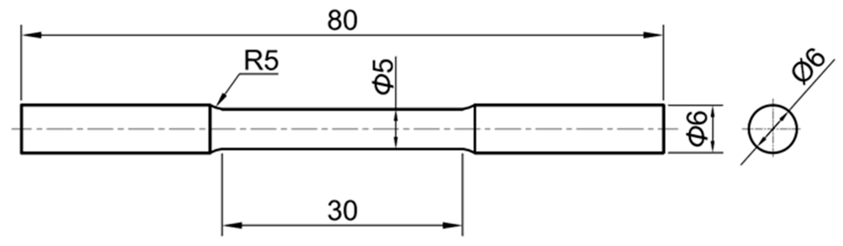
Figure 2.
Observed surface of crystal grain size.
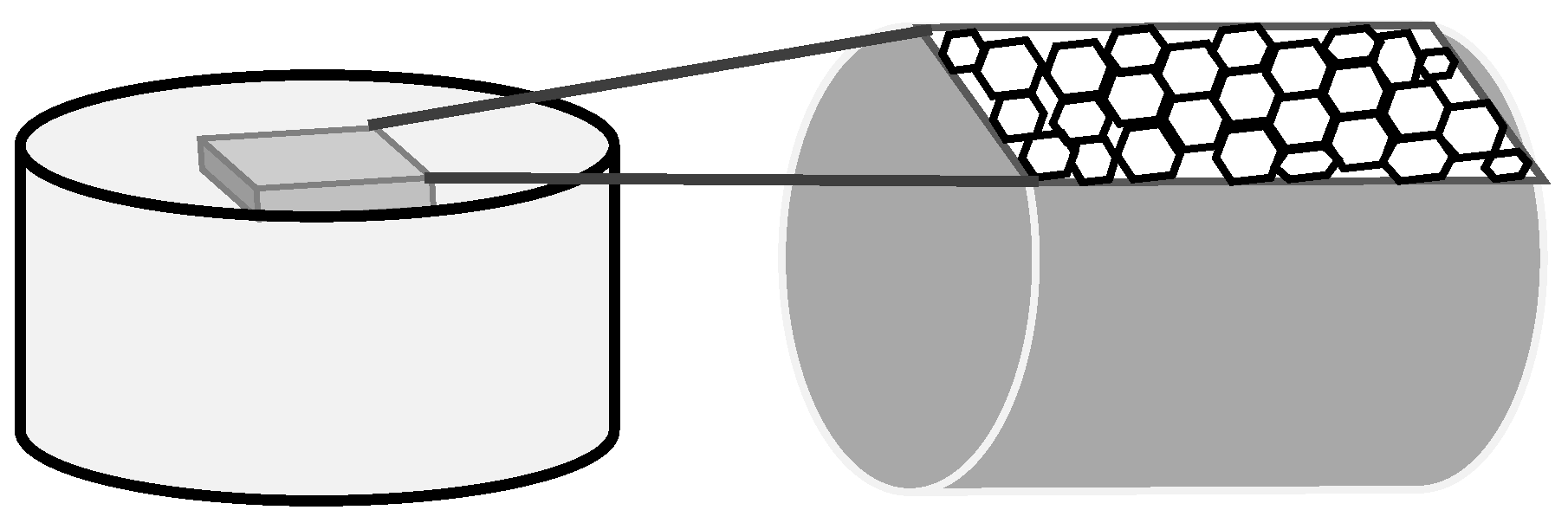
Figure 3.
Mass loss (Ⅰ)(Ⅱ) and corrosion ratio (Ⅲ)(Ⅳ) of pure magnesium with tensile strain after 24(h) immersion test. (Ⅰ) ε= 0.05, (Ⅱ) ε ≒ 0.07, (Ⅲ) ε= 0.05, (Ⅳ) ε≒ 0.07.
Figure 3.
Mass loss (Ⅰ)(Ⅱ) and corrosion ratio (Ⅲ)(Ⅳ) of pure magnesium with tensile strain after 24(h) immersion test. (Ⅰ) ε= 0.05, (Ⅱ) ε ≒ 0.07, (Ⅲ) ε= 0.05, (Ⅳ) ε≒ 0.07.
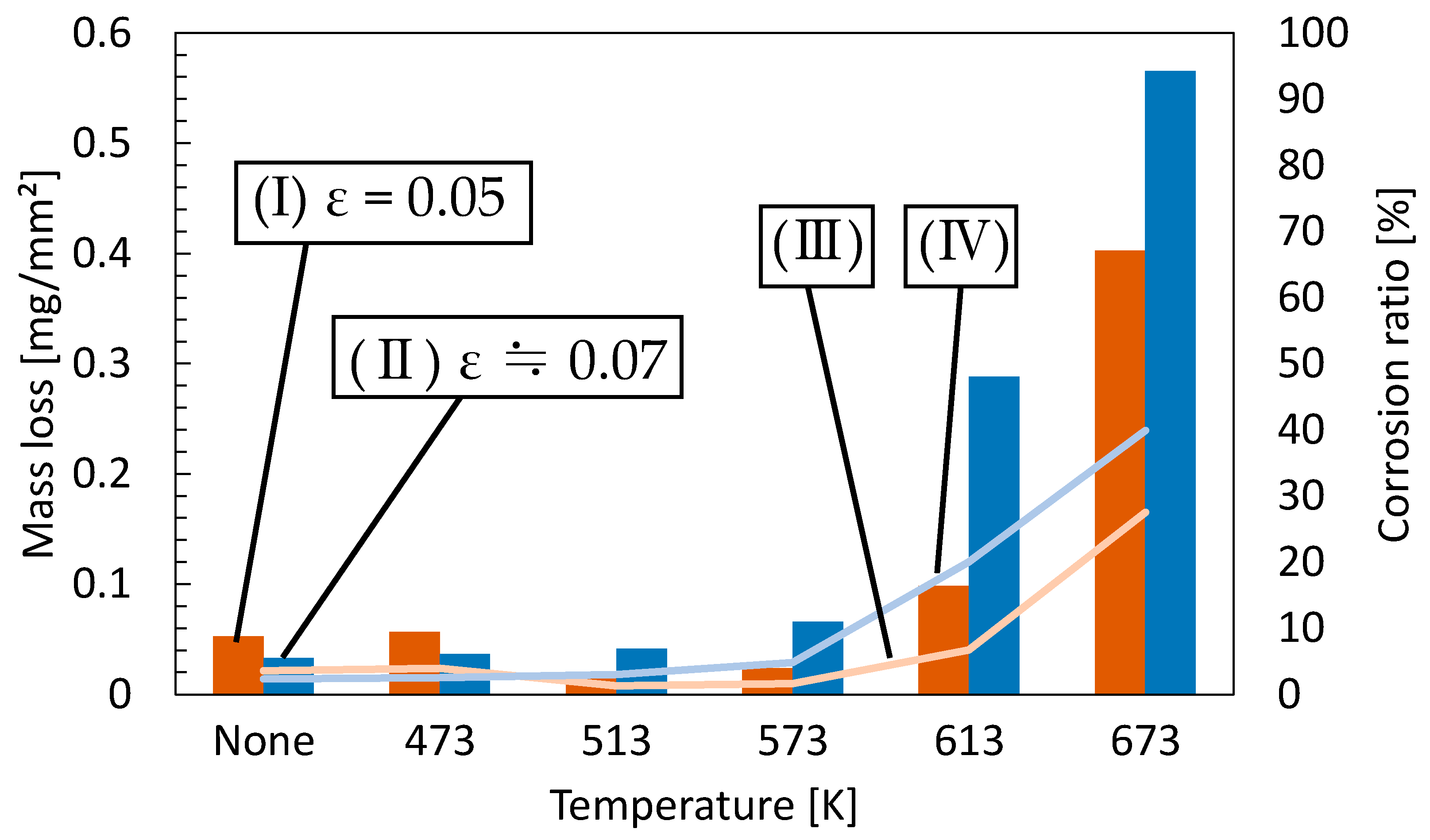
Figure 4.
Optical micrographs of pure magnesium. (a) 513K_ε= 0, (b) 673K_ε= 0, (c) 513K_tensile strain of 0.05 and (d) 673K_tensile strain of 0.05.
Figure 4.
Optical micrographs of pure magnesium. (a) 513K_ε= 0, (b) 673K_ε= 0, (c) 513K_tensile strain of 0.05 and (d) 673K_tensile strain of 0.05.
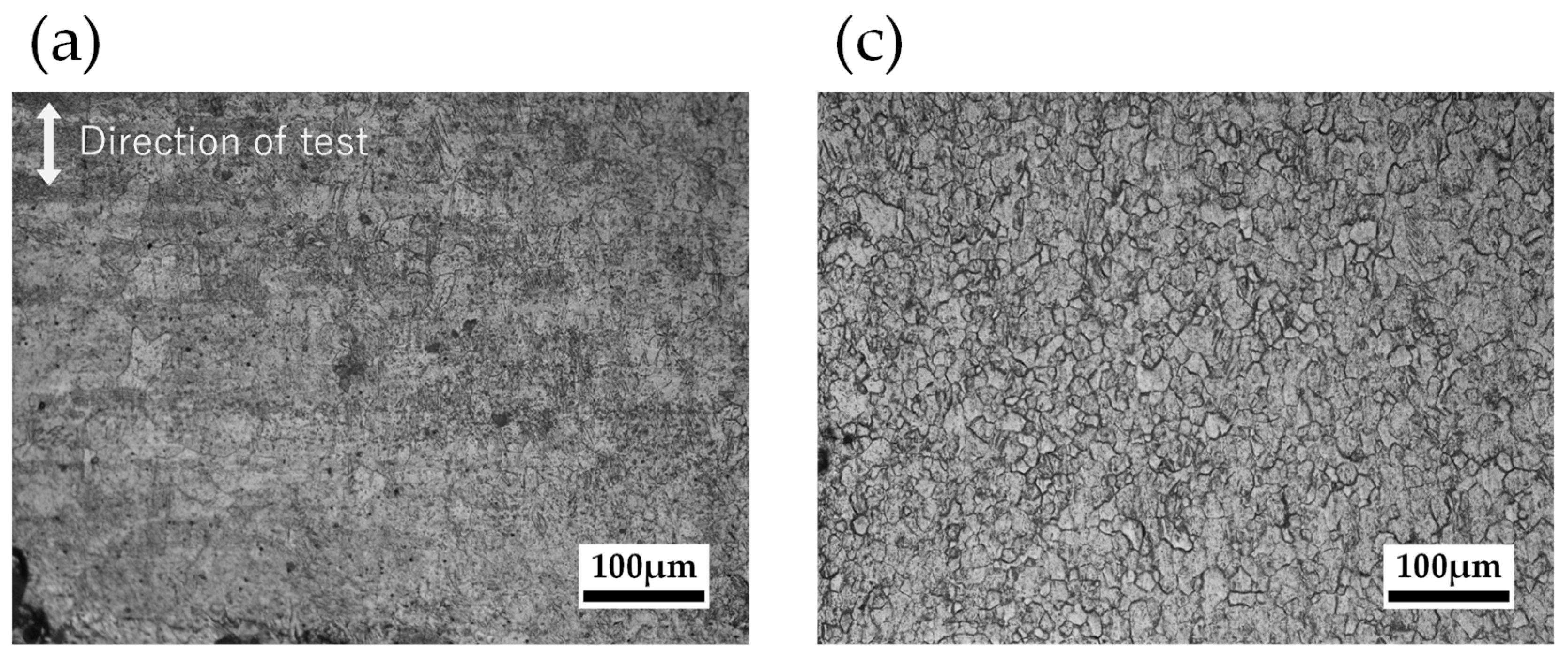
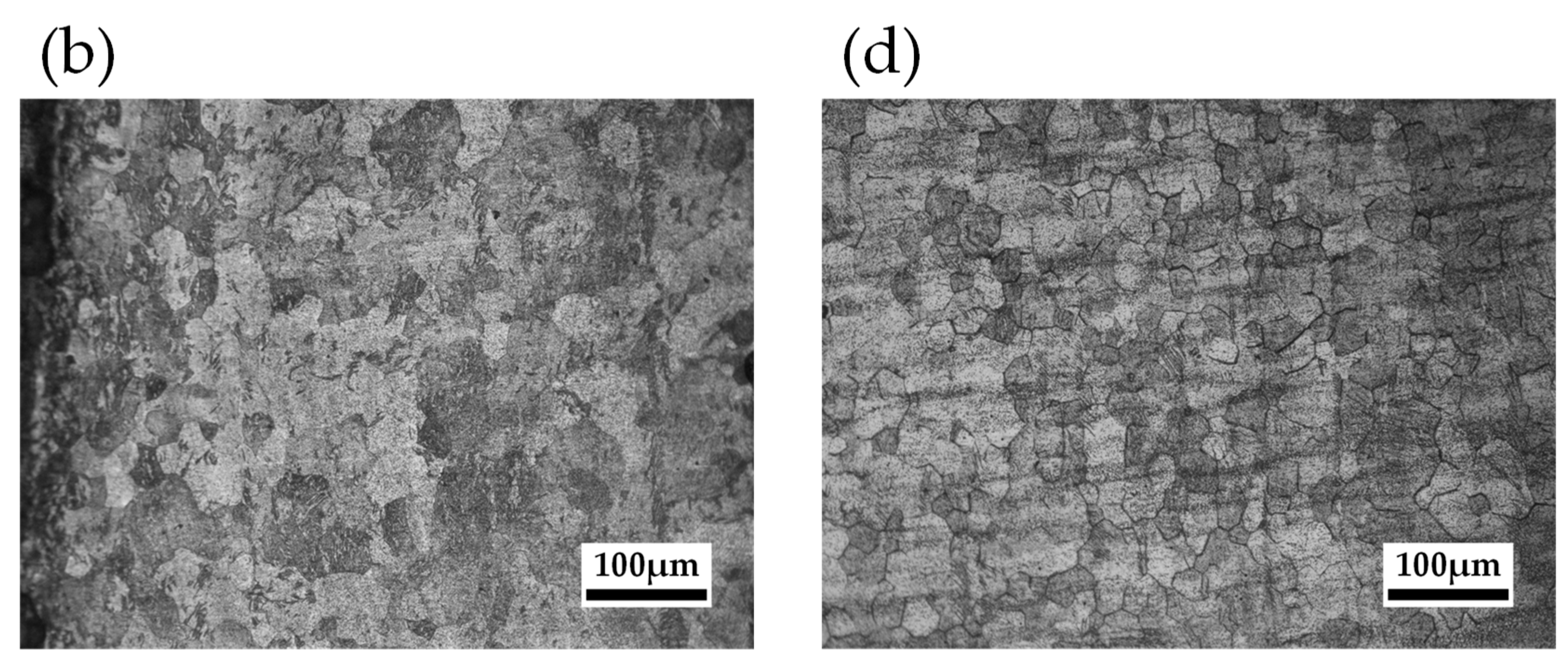
Figure 5.
Mass loss (Ⅰ), (Ⅱ) and corrosion ratio (Ⅲ), (Ⅳ) of pure magnesium with compressive strain after 24(h) immersion test. (Ⅰ) ε= 0.05, (Ⅱ) ε= 0.1, (Ⅲ) ε= 0.05, (Ⅳ) ε= 0.1.
Figure 5.
Mass loss (Ⅰ), (Ⅱ) and corrosion ratio (Ⅲ), (Ⅳ) of pure magnesium with compressive strain after 24(h) immersion test. (Ⅰ) ε= 0.05, (Ⅱ) ε= 0.1, (Ⅲ) ε= 0.05, (Ⅳ) ε= 0.1.
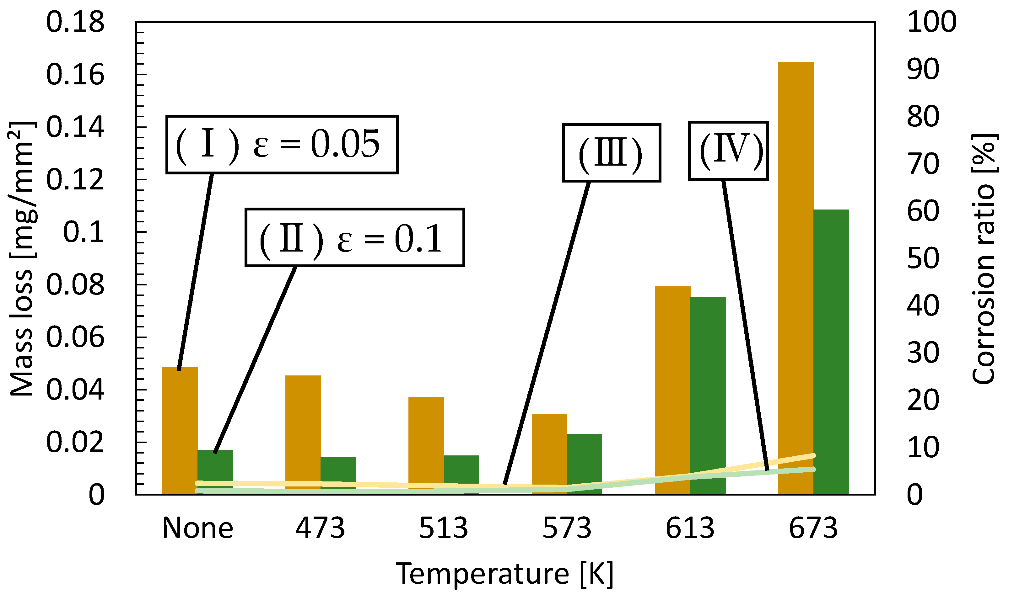
Figure 6.
Optical micrographs of pure magnesium. (a) 513K_ε= 0, (b) 673K_ε= 0, (c) 513K_compressive strain of 0.05 and (d) 673K_compressive strain of 0.05.
Figure 6.
Optical micrographs of pure magnesium. (a) 513K_ε= 0, (b) 673K_ε= 0, (c) 513K_compressive strain of 0.05 and (d) 673K_compressive strain of 0.05.
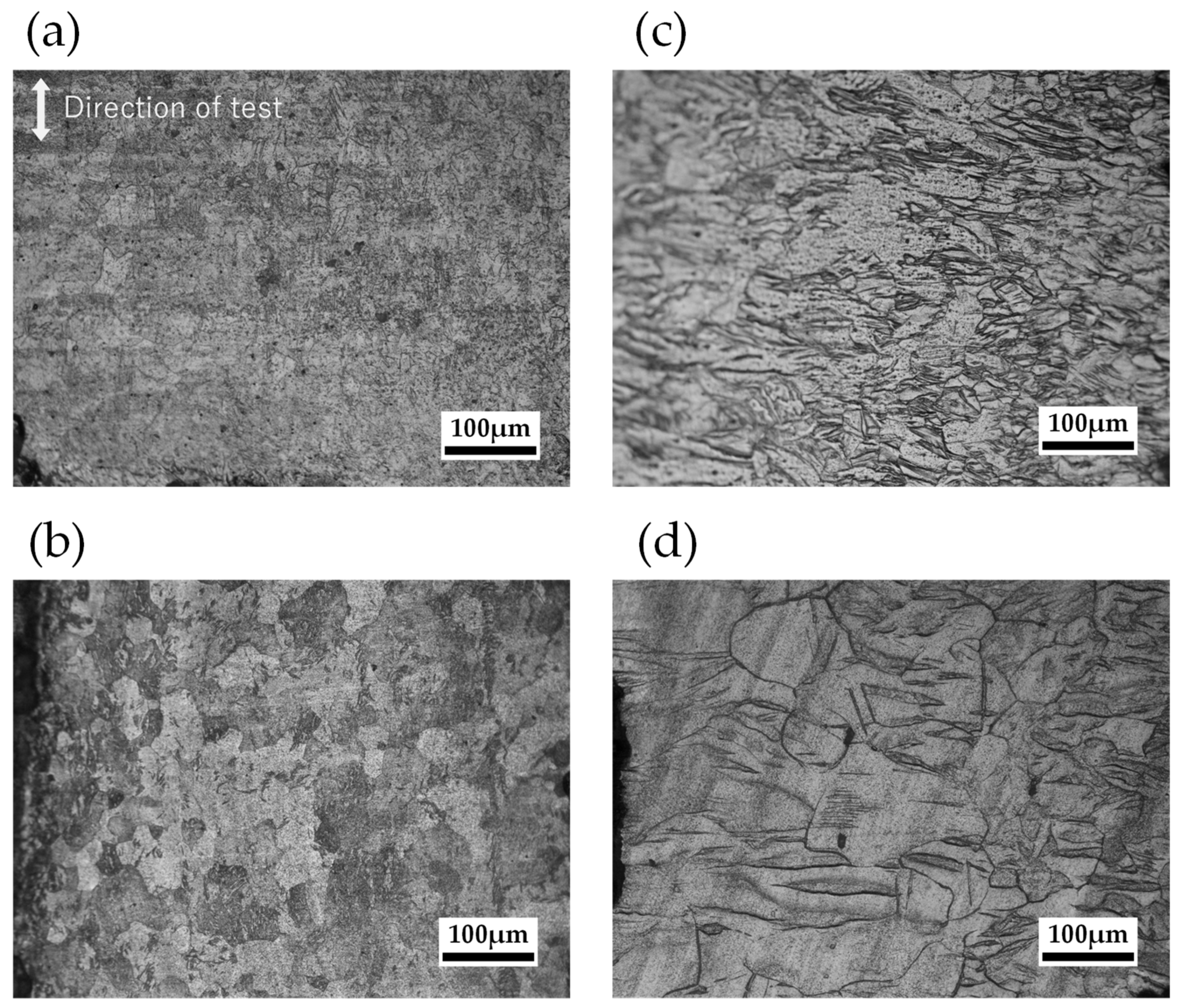
Figure 7.
Pure magnesium samples size for fatigue test.
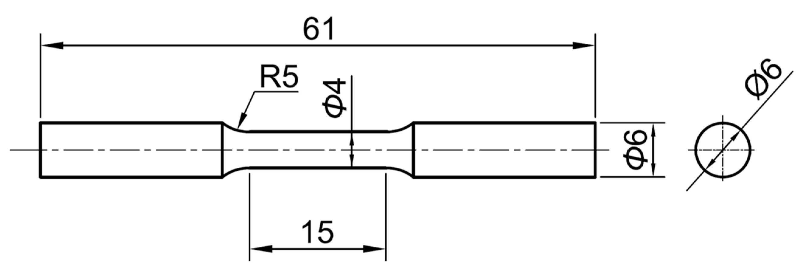
Figure 8.
Mass loss of pure magnesium at annealing temperatures of 513 and 673 K and cyclic stress of 0, 10, 20, 30, and 40 MPa after 24(h) immersion test.
Figure 8.
Mass loss of pure magnesium at annealing temperatures of 513 and 673 K and cyclic stress of 0, 10, 20, 30, and 40 MPa after 24(h) immersion test.
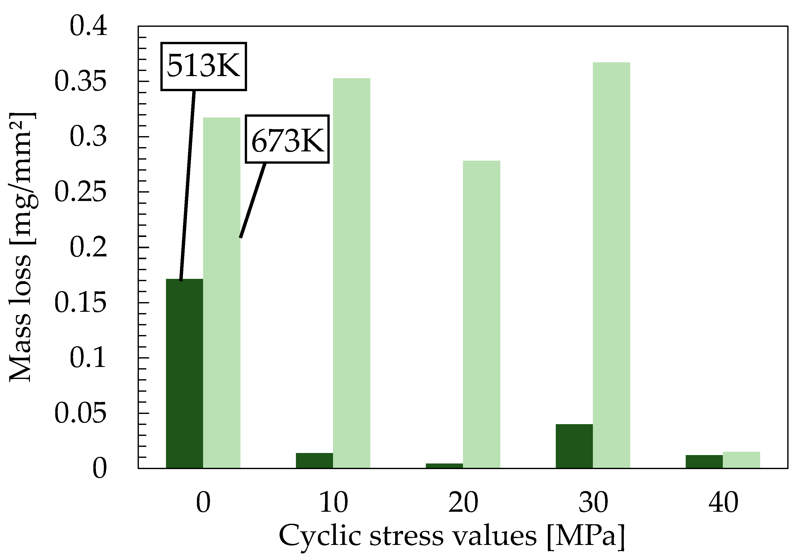
Figure 9.
Optical micrographs of pure magnesium. (a) 513K_cyclic stress of 0 MPa from Figure 3, (b) 513K_cyclic stress of 10 MPa, (c) 513K_cyclic stress of 20 MPa, (d) 513K_cyclic stress of 30 MPa, (e) 513K_cyclic stress of 40 MPa, (f) 673K_cyclic stress of 0 MPa from Figure 3, (g) 673K_cyclic stress of 10MPa, (h) 673K_ cyclic stress of 20 MPa and (i) 673K_ cyclic stress of 30 MPa, (j) 673K_cyclic stress of 40MPa.
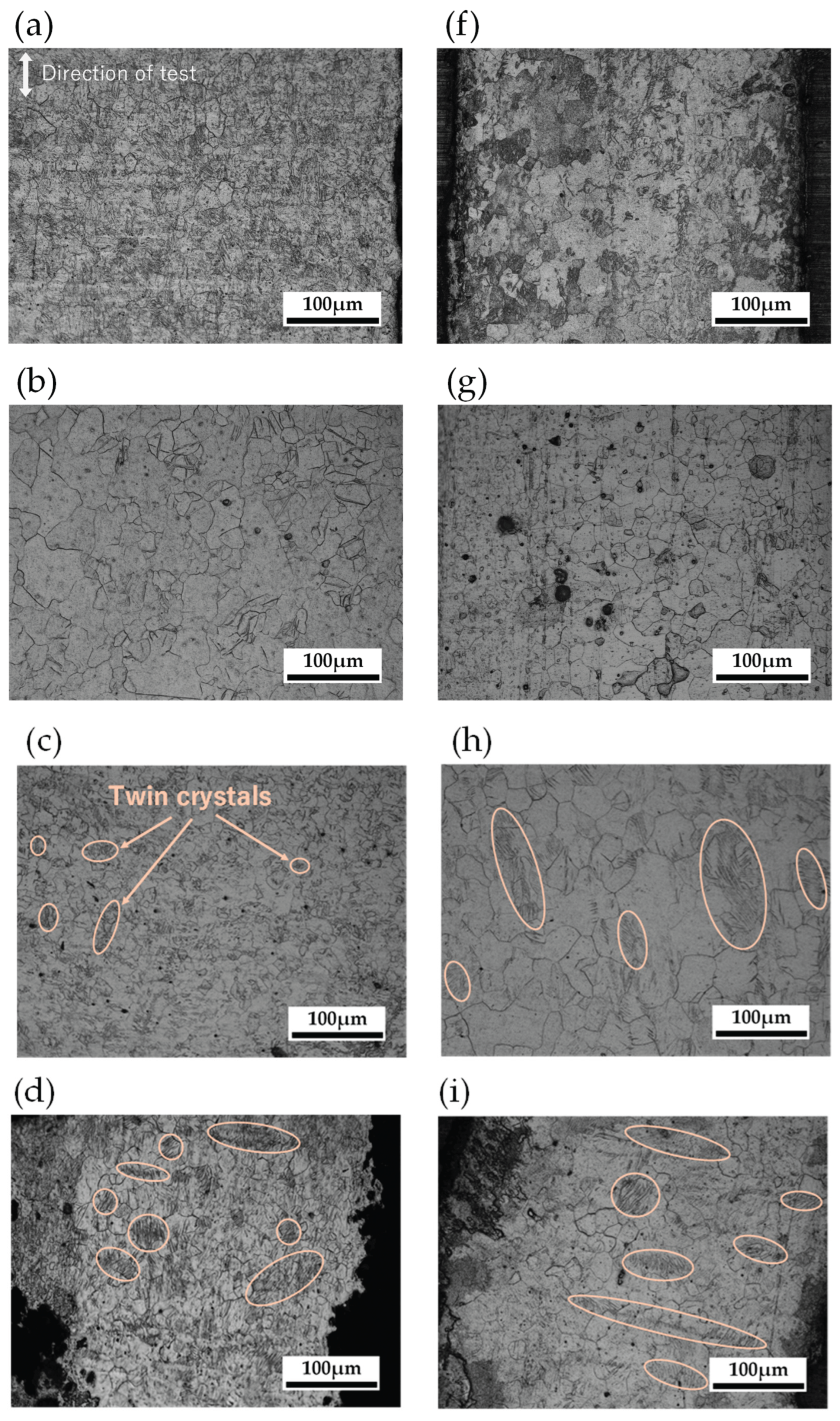
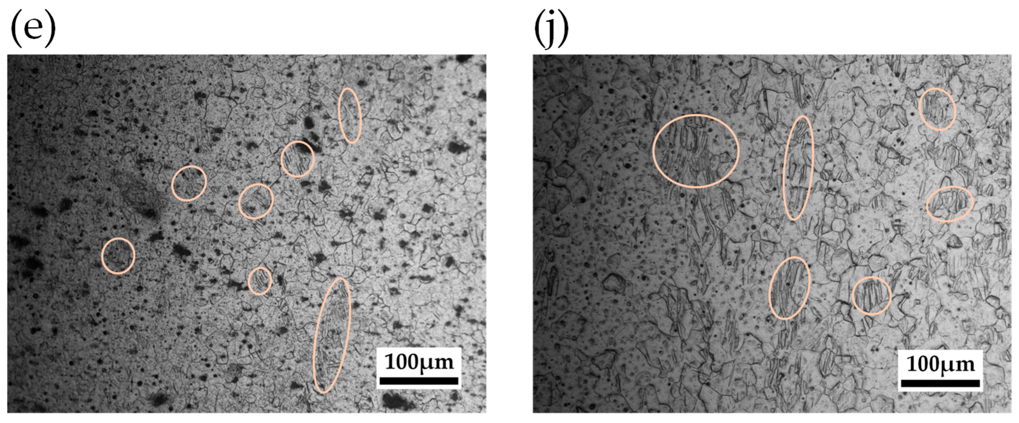

Table 1.
Annealing conditions for pure magnesium.
| Annealing Time [h] | 0 | 1 | ||||
| Temperature [K] | none | 473 | 513 | 573 | 613 | 673 |
Table 2.
Corrosion immersion test conditions.
| Solution | 0.9 (mass%) NaCl |
| Corrosion time [h] | 24 |
| Corrosive environment | immersion |
Table 3.
Cyclic tensile and compressive stress conditions.
| Stress ratio | -1 |
| Environment | atmosphere |
| Frequency [Hz] | 20 |
| Number of cycles [N] | 2.0×10⁷ |
| Tensile stress [MPa] | 10, 20, 30, 40 |
| Compressive stress [MPa] | 10, 20, 30, 40 |
Disclaimer/Publisher’s Note: The statements, opinions and data contained in all publications are solely those of the individual author(s) and contributor(s) and not of MDPI and/or the editor(s). MDPI and/or the editor(s) disclaim responsibility for any injury to people or property resulting from any ideas, methods, instructions or products referred to in the content. |
© 2025 by the authors. Licensee MDPI, Basel, Switzerland. This article is an open access article distributed under the terms and conditions of the Creative Commons Attribution (CC BY) license (http://creativecommons.org/licenses/by/4.0/).
Copyright: This open access article is published under a Creative Commons CC BY 4.0 license, which permit the free download, distribution, and reuse, provided that the author and preprint are cited in any reuse.


