
Submitted:
02 January 2025
Posted:
03 January 2025
You are already at the latest version
Abstract
The removal of prosthetic implants, although normally necessary following the recovery of patients, inevitably has disadvantages in terms of costs, further pains and possible post-operative infections. A promising alternative is represented using bioresorbable implant structures. The magnesium alloy-based devices could be ideal candidate due to their poor corrosion resistance and high biocompatibility, but their degradation rate is dissimilar to that of hosting tissues healing. Therefore, a growing interest is addressed to design new magnesium alloys with a slow degradation process or to modify the surface of known magnesium alloys. This paper aims to investigate the enhancement of corrosion resistance of a protective system applied on the AZ31 magnesium alloy composed of three different superimposed layers: a) magnesium-based oxide, b) polydopamine and c) polylactic acid. Morphological and chemical analysis were performed. Roughness and microhardness measurements were carried out. Electrochemical behavior was studied in the Hanks’ solution at 37 °C. As expected, the findings showed that the magnesium oxide layer is able to reduce the degradation rate, in contrast to the polydopamine layer, that negatively affected the barrier protection of the only anodization. However, the presence of polydopamine together with the polylactic acid film improved the corrosion resistance of the alloy. Thus, the multilayers should represent a protective system to control the degradation process.
Keywords:
micro-arc oxidation
; biodegradable implants magnesium alloys-based
; degradation control
; polydopamine
; polylactic acid
1. Introduction
An important and essential challenge for using metallic materials to make biodegradable medical devices is ensuring a controlled biodegradation process during the reconstruction of the hosting tissue. A major contribution to solving this problem could be provided using magnesium alloys, which exhibit some remarkable chemical/physical properties [1]. Magnesium, being a crucial human element for the body [2], guarantees a high biocompatibility of its alloys which exhibit mechanical properties similar to those of human bone, with an elastic modulus, E, of 45 GPa, and a low density, ρ =1.74 g/cm3, compared to other alloys used in the biomedical field [3]. These peculiarities make the magnesium alloys are potentially useful for the creation of devices such as biodegradable implants, plates, prostheses, screws, etc. [4,5]. However, the intrinsic rapid degradation of these alloys in the human environment can inevitably lead to uncontrolled impairment of mechanical properties, the production of gas bubbles at the implant/tissue interface with obvious problems in the healing phase and problems with delamination and alkalization of surrounding tissues due to the production of hydroxyl ions [6]. Two strategies to overcome these drawbacks could be the design of an ad hoc alloy with appropriate chemical/physical properties or the use of coatings in order to ensure, in both cases, adequate and controlled degradation kinetics of the material. Numerous surface treatment, including anodizing [7,8], conversion layers [9,10] and organic coatings [11,12], have been studied to slow the rate of magnesium corrosion in biological environments. The anodizing, in particular the Plasma Electrolytic Oxidation (PEO), also defined Micro Arc Oxidation (MAO), which is a very hard-anodizing treatment, in which the potential applied breakdown the coating formed, has been widely used in various experimental studies [13]. The PEO treatment allows the growth an oxide layer very adherent to the substrate due to the spark discharges formed on it causing its localized melting/remelting. It is a complex treatment, in which chemical and electrochemical reactions occur simultaneously. Several parameters can be modified to obtain a defined morphology, thickness and chemical composition. For example, the morphology and thickness could be affected by the current or voltage applied, as well as by the metallurgical composition of the substrate [14]. On the other hand, the chemical composition could be influenced by the electrolyte used during the treatment [15].
Similarly, various types of surface treatments leading to the formation of protective layers are being actively studied [16]. Hydrothermal treatments, for example, have been used to obtain films composed of Mg5(CO3)4(OH)2·4H2O particles with a “flower-like” spherical morphology [17], while electrodeposition treatments have been used to form hydroxyapatite layers [18]. Chemical treatments, on the other hand, often showed the difficulty to cover the whole substrate, with the consequence to facilitate the corrosion phenomena [19]. Another approach to control the degradation rate is using synthetic organic coatings based on biodegradable polymers, as polycaprolactone (PCL) and polylactic acid (PLA) [20,21,22], or natural organic coating, made of chitosan, alginate, cellulose and go on [23]. If the use of the latter presented difficulties in achieving homogeneous and high-quality coating, the former presented poor adhesion [24]. PEO/Polymer hybrid coatings on magnesium alloy [25,26] to improve biodegradation and biocompatibility properties have already proven to be a very encouraging methodology for modifying the interface properties of materials, as reported by Munoz et al. [27], which demonstrated how the use of PLA on a PEO-treated AZ31 sample improves both its fracture strength and corrosion resistance. A possible alternative to this approach is design a multilayer protective system, in which each layer can perform a specific task and work in synergy with the others [28,29,30]. Wei et al. [31] investigated the corrosion behavior and haemocompatibility/cytotoxicity of a magnesium alloy AZ31, used for biodegradable cardiovascular stents, on which PEO was first carried out, then coated with a Poly-l-Lactic Acid (PLLA) layer and finally with a polydopamine layer. Polydopamine (PDA) is the product of the polymerization of dopamine, the building block of adhesive proteins that make up the mussel plates and allow them to attach to different types of substrates in a wet or dry environment [32]. It was used to immobilize heparin, which is an anticoagulant that reduces the risk of thrombus formation in the proximity of the implant. However, although external layer of a polydopamine-based coating improves the heparinization, the authors discovered a worst corrosion resistance when the acid polylactic layer was coated with the polydopamine film, probably due to a partial hydrolysis of the PLLA during the coating treatment. On the other hand, Tian et al. [33] evaluated the corrosion resistance and cytotoxicity of an AZ31 specimen subjected to PEO treatment, coated first with PCL and then with polyhexamethylene (PHMB), which had an antibacterial function, applied using polydopamine. In contrast to previous paper, the application of polydopamine did not deteriorate the underlying organic film in terms of corrosion resistance.
This paper aimed to realize a multilayer protective system overlapping a first layer of magnesium-based oxide, obtained using the PEO technique, on which, in contrast to the previous papers, the polydopamine was used as intermediate layer, sealing the system with the last film of polylactic acid. In addition, the polydopamine layer was applied to the substrate with a green technology, never found in literature to the best knowledge of the authors, avoiding the use of strong chemical compounds. The three layers, therefore, are hypothesized to provide: i) increased corrosion resistance of the base alloy, ii) sealing of the pores present in the oxide layer and iii) better control of the corrosion kinetics of the metal substrate which, thanks to the presence of the polydopamine layer between the oxide and the film of PLA, will degrade slowly.
2. Materials and Methods
2.1. Sample Preparation
Wrought rectangular sheets (10mm x 50 mm x 3 mm) of AZ31 magnesium alloy (Goodfellow Cambridge Ltd.) with the nominal composition of 2.5-3.5 % Al, 0.7-1.3 % Zn, 0.2-1 % Mn, and balanced Mg, were used as substrate. The Hanks’ Balanced Salt solution was used as a physiological one. All chemical reagents were supplied by Merck (Merck KGaA, Darmstadt, Germany). The PLA film, 80 ± 5 µm thick, was obtained supplied by Total Energies Corbion (Total Energies Corbion, Gorinchem, The Netherlands).
All samples were previously mechanically polished by using sandpapers up to 1200 grit with ethanol as lubricant. Then, the specimens were washed in ethanol and dried in a compressed air flow.
2.1.1. Treatment: Micro-Arc Oxidation
The micro arc oxidation (MAO) treatment was conducted in a silicate-based solution (0.04 M) and sodium hydroxide (0.05 M) using the cell schematized in Figure 1 [34]. The magnesium specimens, used as an anode, with an exposed area of 1 cm2 and appropriately protected on the rest of the surface with a red shielding tape, and a platinum plate used as a cathode were connected to the power source (TDK, Lambda, Milan). A hanging agitator ensured a continuous mixing of the electrolyte (40 rpm), while the coolant maintained a temperature of the bath lower to 20 ± 2 °C. The anodization was performed in galvanostatic condition, applying a current density value of 0.030 A/cm2 for 1200 s. At the conclusion of the anodizing, the specimens were washed in distilled water and dried in a compressed air flow.
2.1.2. Bio-Inspired Coating
The anodized specimens were dipped for 3 h in the mild stirred bio-inspired solution, composed of 0.2 g of dopamine hydrochloride (C8H11NO2 · HCl) in 100 mL of 0.01M Tris (C4H11NO3) buffer solution (pH 8.5), prepared an hour before the treatment to allow the polymerization process [35]. The specimens were, then, washed under distilled water flow and dried in a jet cold air. Although the coating deposited was very thin, about ten nm, a brown coloration was observed on the specimens’ surface.
2.1.3. Polylactic Acid Film
The last layer covering the specimens was made of a biodegradable polymer, the polylactic acid, applied using a green technology, i.e., by hot pressing, which avoids the use of strong chemical solvents, otherwise necessary to dissolve the PLA [27]. Briefly, a PLA film, placed on the treated samples (by anodization and/or bio-inspired deposition), was pressed onto them by applying 2 bar for 300 s at a temperature of 170 °C. The reported parameters are the results of a long previous experimental campaign aimed to obtain an outstanding adhesion between the substrates and the biodegradable film.
The final structure of the sample including the coating consisting of an inner layer of anodic oxide, an intermediate layer of polydopamine, and an outer PLA film is visualized in Figure 2.
In particular, six types of samples were prepared, hereinafter indicated as follows: 1) Mg SS (Mg alloy untreated); 2) Mg-PDA (Mg alloy covered with only a polydopamine layer; 3) Mg-PLA (Mg alloy covered with only a PLA film; 4) Mg-MAO (Mg alloy after the anodization); 5) Mg-MAO-PDA (Mg alloy after the anodization and the deposition of polydopamine layer); 6) Mg-MAO-PDA-PLA (Mg alloy after the anodization, the deposition of polydopamine layer and the application of the PLA film).
2.2. Surface Characterizations
Surface morphological features were captured with a confocal laser scanning microscope (Lext 5100, Olympus Evident, Japanese) and a scanning electron microscope (SEM, Mod. FEI QUANTA 200 F) at an accelerating voltage of 20 kV in a high vacuum condition, connected with an energy dispersive X-ray analysis (EDX) probe. After the chemical analysis, the specimens were sputtered with an ultrathin conductive layer based on gold alloy. The images were taken at 500x. The crystallographic structure of the oxide layer was investigated by Gracing Incidence X-Ray Diffraction analysis (GI-XRD, PANalytical X’Pert PRO). The roughness measurements of the anodized specimens were carried out using the confocal laser scanning microscope abovementioned, considering some of the most useful roughness parameters, as reported in previous paper [36]. Three different area of about 62.5 mm2 were analyzed for each type of samples, and the average value of roughness parameters was calculated. The hardness of the oxide coating was evaluated with a Vickers micro-hardness test (HX-1000 Remet) on the top view, using a load of 100 g (HV0.1) applied for 15 s. The average value of ten measurements of each specimen was reported.
To study the corrosion characteristics in-vitro potentiodynamic polarization (PDP) and electrochemical impedance spectroscopy (EIS) analyses were carried out employing a potentiostat with a frequency response analyzer integrated (Interface 1010E, Gamry, United States). The latter instrument was connected to a classical electrochemical system, in which the specimens were used as working electrode; a platinum wire was linked to the counter electrode while a saturated calomel electrode (SCE) was used as a reference electrode to measure the working electrode potential. The electrolyte consisted of a Hanks’ solution [37] maintained at body temperature by means of a thermostatic bath. The open circuit potential (OCP) value, observed for ten minutes, was used to polarize the specimens from -300 mV against the OCP until a current density value of 1 mA/cm2, with a sweep rate of 0.166 mV/s. If the PDP is a single time point test which changes the surface specimen, the EIS allows to study the alteration of it over time. The EIS spectra were recorded for 7 days by applying a low intensity potential signal in AC regime in the frequency range from 50 x105 Hz to 2 x 10⁻² Hz. The Hanks’ solution has been changed every day. The tests’ reproducibility was ensured repeating all analysis three-fold.
3. Results
3.1. Morphological and Chemical Analysis
The images in Figure 3 depict the appearance taken by the specimens before and after the polydopamine deposition and/or anodization. They different coloration is due to the presence of the brown polydopamine layer on Mg-PDA specimen, the grey oxide anodic coating on Mg-MAO specimen while the light brown on Mg-MAO-PDA specimen is due to the polydopamine layer on porous structure of the oxide coating.
The SEM observations reported in Figure 4 reveal the effect of the polydopamine on magnesium substrate, which tends to degrade due to the pH value of polydopamine bath. According to the Pourbaix diagram, the magnesium in contact with aqueous solution at pH value of 8,5 produce Mg2+ ions [38], in other words it corrodes. In particular, the surface appeared cracked [39], although the grooves generated during the mechanical pretreatment are still evident, suggesting the formation of a very thin but not uniform thickness polydopamine layer. As previously reported [40], the cracked morphology could be attributed to the dehydration of the polydopamine layer during the drying phase of the treatment. Whereas, the anodization involves the well-known pancake like feature, with several pores with an average diameter of 2.5 ± 0.8 µm, and random oblongs pores having larger diameters, generated by the coalescence of multiple pores. When the polydopamine covers the oxide anodic coating a widening of the porosity was observed, as the mussel-inspired layer could internally erode the oxide pores. This aspect remains an issue of discussion.
The cross-section view of Mg-MAO specimen show a thickness of about 13.3 ± 2.2 µm and a structure consisting of a very thin barrier layer covered by an outer layer with large pores between the dense inner layer and the porous one, confirming the development of gas during the anodizing in this region, widely reported in literature.
The EDX analysis performed on the Mg specimen (Figure 6a) show the presence of oxygen, in addition to the main component of the alloy, zinc and aluminum, due to the high reactivity of magnesium with the oxygen which involve an easy growth of oxide on its surface. The chloride peak could be due to the residual of acid used during the pretreatment for etching the surface. The additional carbon and nitrogen peaks on the PDA-coated specimen demonstrate the deposition of the thin polydopamine layer (Figure 6b). On the anodized sample, in addition to the elements constituting the alloy, aluminum and zinc, oxygen was also detected, due to the formation of the anodic oxide coating, contaminated by the silicon and sodium elements present in the electrolytic solution, dragged inside by the micro-discharge channels created during the MAO treatment (Figure 6c). The specimen covered with the polydopamine layer on the oxide coating exhibits all the previous shown peaks.
In Figure 7 the SEM cross-section view of the specimen after the micro-arc oxidation treatment, the polydopamine deposition and the PLA hot pressed is depicted. The polydopamine layer, being very thin, was difficult to detect. However, it was possible to see that the hot pressing reduced the thickness of the PLA at about 25 ± 2 µm.
3.2. Crystallographic Analysis
In Figure 8 the XRD spectra of the only anodized compared to the untreated samples are reported, in order to investigate the crystallographic structure of the oxide layer. From the analysis of the characteristic peaks, it can be seen that peaks corresponding to the MgO and Mg2SiO4 phases are present in the anodized sample. This confirms the theoretical finding that, as a result of the continuous melting and re-solidification of the oxide during the complex PEO process, there is an enrichment of the composition of the coating, which will eventually also contain the elements present in the electrolyte [41]. In addition, Mg-associated peaks representing the metal substrate were observed, suggesting the penetration of the X-ray in the bulk of the substrate, although a gracing incidence analysis was carried out.
3.3. Micro-Hardness Test
The ceramic-like characteristic of the oxide layer should provide good hardness properties, depending on the phase structure and compactness. The oxide coating, given its ceramic nature, show higher values of this parameter compared to the magnesium substrate, as reported in Figure 9. Specifically, the magnesium substrate records a value of about 77 ± 5 HV, whereas the anodic coating presents a microhardness of about 324 ± 20 HV, higher than values reported in literature [42]. The contribution of the organic coating does not provide any substantial change in the hardness of the sample, so it was not reported.
3.4. Roughness Measurements
The surface roughness parameters values obtained by performing the measurements by means of the laser confocal scanning microscope are listed in Table 1.
From the results it is interesting to note the effect of the PDA deposition when it is applied on both the magnesium substrate and the oxide coating. In the first case (Mg-PDA specimen), as expected, a change of the Sa parameter is recoded from 0,3 to 1,3 µm. In addition, an erosion effect can be detected observing the higher values of Sp and Sv, suggesting higher peaks and lower valleys. As a result, the resulting developed area, Sdr, increases from 2,1% to about 40%. The only anodization treatment (Mg-MAO) further amplifies the distance between the peaks and the valley, extending the developed area of about 300% (Sdr), and produces a morphology characterized by sharp peaks and a prominence of valleys, as shown by the Sku and Ssk values, respectively. The deposition of the mussel-inspired coating (polidopamina layer) on the anodized specimen, on the other hand, reduces the peak-to-valley distance by filling the porosity and significantly smooths the surface, as evidenced by the reduction of Sdq value of 1%, particularly changing the shape of the peaks as attested by the reduced value of Sku.
The 3D roughness graphs are displayed in Figure 10. The magnesium substrate has a smooth surface with evident grooves due to mechanical pretreatment. The erosive effect of the polydopamine layer can be detected on Mg-PDA samples, whose surface appears rough. The anodizing treatment results in a very porous surface, with clear sharp peaks and deep valleys. The polydopamine layer on the anodic coating dilats the pores, smoothing the peaks and filling the valleys, as evidenced by the lack of blue zones (see Figure 10 Mg-MAO-PDA sample).
Although the importance of the surface topography for cell adhesion, migration, differentiation, and proliferation processes is widely discussed in literature [43], and it is established that the cells are able to recognizer the chemical [44] and the topography of the substrate, used as contact guidance for their development process, the topic remains very complex, since a surface can be characterized by different levels of roughness: macro-, micro-, submicron- and/or nano. At the same time, it could present pits, grooves, fibers or pores with a chaotic or ordinate texture. Several papers [45,46,47,48,49] investigated the influence of an isotropic or anisotropic pattern on the cells’ behavior, revealing a better response in the former case and defining also the beneficial size and shape of the micro chambers composing the pattern, considering the cells size (about 10-20 µm). Nikkahn et al. [50] studied the influence of two kind of 3D isotropic pattern of a silicon substrate, designed with a star or circular micro chambers of about 150 µm width and 50 µm depth, on the adhesion of human fibroblast cells and human breast cancer cells (MDA-MB-231), demonstrating the different influence of the micro chamber’s shape on the adhesion mechanism between healthy and diseased cells. Altomare et al. [51] investigated several variety of grooves depths (0.5-5 µm) and widths (5-100 µm) to improve myoblast cells behavior on a PLA/trimethylene carbonate copolymer film. The authors, although found the best finding on deeper and narrower grooves, they highlighted the importance to study also the behavior for long-time period, due to the improvement of the cellular development after the first days. Different techniques are list in the literature to obtain desiderata 3D micro patterns [43]. In this work, the hot-pressing technique used to apply the PLA film allows a specific surface pattern to be imprinted and used as contact guidance, with the opportunity of possibly also choosing the valleys shape and size to stimulate the regenerative processes of the host tissue. The 3D graph of the Mg-MAO-PDA-PLA sample, displayed in Figure 11, shows an isotropic pattern, characterized by circle micro chambers, of the PLA film.
To verify the shape of the valleys, profile measurements were taken along perpendicular directions, a representation of which is shown in Figure 12. It is possible to note the curved side walls of the valleys, characterized by a width of approximately 400 µm and a depth of approximately 5 µm.
3.5. Electrochemical In-Vitro Characterization
The potentiodynamic polarization scans are displayed in Figure 13. The poor corrosion resistance of magnesium and its alloys was broadly investigated and exhibited from the electrochemical response obtained in various environments, including the body human one. As displayed in Figure 13, the Mg SS curve shows the highest current density value and a low corrosion potential, Ecorr, of about 1.48 V vs SCE. The deposition of the polydopamine layer, while recording a near corrosion potential value against the Mg SS, reduces the corrosion rate of about one order of magnitude [52]. Instead, when the plasma electrolytic oxidation is performed a decrease of two order magnitude is possible to detect, along with an increase of the corrosion potential (about 1,32 V vs SCE). It should not be surprising the lack of a passivity range due to the porosity characterizing the coating, as recorded for aluminum alloys [53,54]. The dipping in the polydopamine bath after the anodizing has somehow compromised the beneficial effect of oxidation because a reduction of the Ecorr and icorr compared to those of Mg-MAO specimen is exhibited. However, it seems possible to appreciate a pseudo-passivity, due to the polydopamine penetrating pores, which simultaneously enlarging and sealing them, as highlighted by roughness measurement. The above considerations can be applied if the geometrical area is considered (Figure 13a), but from roughness measurements is possible to take into account the real extension of the area due to the anodizing treatment. This allows an impressive reduction of the corrosion rate evident as the translation of the curves towards lower current densities (Figure 13b).
The lack of activation mechanism and the quickly reaching of a trans-passivity condition not allow to calculate the corrosion rate using the Tafel approach. In these cases, an extrapolation of the above-mentioned approach is possible applying for determining the corrosion current density, identified as the intersection point between the tangent to the cathodic branch and the corrosion potential, Ecorr. The Mg SS samples shows a corrosion current density of 2.85 ± 0.3 x 10⁻⁵ A cm-2. The anodized sample Mg-MAO records a very low corrosion current density of 5.99 ± 0.8 x 10⁻¹⁰ A cm-2. The only polydopamine layer (Mg-PDA) improves the corrosion current density compared to the untreated sample, 1.94 ± 0.3 x 10⁻⁷ A cm-2 due to the formation of a rough surface. For the Mg-MAO-PDA specimen, instead of the corrosion current density, the pseudo-passivity current density, equal to 7.35 ± 0.4 x 10⁻⁸ A cm-2, is evaluated.
The EIS results performed on all samples allow to derive interesting considerations about the role played by the various constituents of the three-layers coating studied. In Figure 14 the impedance modulus spectra of the specimens obtained at the beginning of immersion in the Hanks’ solution at 37 °C are shown.
As it is well known, magnesium offers poor corrosion resistance in the presence of chloride ions, as confirmed by the response offered by the Mg SS curve. Covering the magnesium substrate with a layer of polydopamine, only negligible improvements is recorded, compared to the unmodified one. The impedance value at the lowest frequencies is one order of magnitude higher. The effect procured by the anodization treatment (Mg-MAO specimen) can be clearly highlighted in the Bode plot, where the impedance modulus increases at low frequencies by about four orders of magnitude compared with the unmodified sample. However, the behavior exhibited by Mg-MAO-PDA specimen confirms the potentiodynamic polarization results by showing a reduction of the impedance modulus by more than two orders of magnitude throughout the frequency range when compared with the anodized sample. This behavior can be justified by considering that during the formation of the polydopamine layer, on both magnesium substrate and the anodized coating, a degradation process is triggered on their surface. The porosity of the oxide layer could have two effects: the first determined by the increase of the specimen area, and the second by the fact that the pores, due to their size, may behave as occluded cells and thus result in autocatalytic corrosion phenomena. When the film of polylactic acid is applied on polydopamine layer or on the anodic oxide coating, it offered the expected barrier protection. However, the best electrochemical response was conferred when the polydopamine layer was used as intermediate one, promoting a synergistic action.
The EIS test was carried out for a prolonged period, compared to the previous investigations [55,56], until 168h of immersion in the test solution and depicted in Figure 15.
An increase of approximately one order of magnitude in the impedance modulus at the lowest frequency of unmodified specimen suggests that a “protective” layer is formed on the material. However, in Figure 16 it is possible to see the distinctly damaged surface of the unmodified specimen, as well as that coated with the polydopamine layer, because of the exposure of the specimens to an aggressive environment. The Mg-MAO-PDA sample, although presents insignificant changes in the impedance modulus during the observation time, superficially shows some points of degradation. For the anodized specimen, despite presenting a significant variation in the impedance modulus, reduced by two orders of magnitude at the lowest frequencies, at the end of the electrochemical test, its surface appears slightly altered with the formation of small white compounds (Mg-MAO sample), probably composed of phosphate and calcium. Future chemical analyses may help define their composition. The effect procured by the presence of the PLA coating is still clear. All samples covered by the PLA film show a low-frequency impedance value of about 2-3 x 10⁴ Ω∙cm2, about an order of magnitude greater than the specimens uncoated. The impedance modulus values, exhibited by these specimens, at high frequency remain of the same order of magnitude, but the only presence of polydopamine layer involve the development of the swelling phenomena, as demonstrated in Figure 16 (Mg-PDA-PLA specimen). The only anodic oxide layer presents very small and few brown points (Mg-MAO-PLA specimen), suggesting a possible initial degradation process. Whereas the contribution of both, the anodic coating and the polydopamine layer, seems to widely reduce the degradation process of the magnesium substrate.
4. Conclusions
Samples of AZ31 magnesium alloy were superficially modified by deposition of a three-layer coating consisting of an internal layer of anodic oxide, obtained by electrolytic plasma oxidation, an intermediate layer based on polydopamine and a film of polylactic acid applied without the use of solvents. The electrochemical treatment involved the classical pancake-like morphology, characterized by many small pores, which have been enlarged and filled by the polydopamine layer. The beneficial effect of the applied coating was highlighted by the electrochemical tests which highlighted a better response of surface modified specimens in terms of corrosion kinetics. The technique used to apply the PLA film offers the possibility also to customize the optimal topography to stimulate the regenerative process of the host tissues. This research demonstrated that a careful design of the coating system, in terms of morphology and thickness, may reduce the degradation process of the magnesium alloys and potentially could improve the healing of the host tissues for biodegradable implants applications.
Author Contributions
“Conceptualization, A.A. and T. M; methodology, A.A.; validation, A.A., P.R. and A.D.; formal analysis, A.A.; investigation, A.A, F. D., P. R., and G.S; data curation, A.A., G. S, F. D.; writing—original draft preparation, A.A.; writing—review and editing, A. A. and P.R.; visualization A.D.; supervision, A.A and T. M. All authors have read and agreed to the published version of the manuscript.
Funding
The research presented in this contribution is partially financed by Government of Italy Ministry of Education University and Research to the Department of Chemical Engineering, Materials and Industrial Production of the University of Napoli Federico II through the PON R&I 2014-2020 – Axis IV “Education and research for recovery – REACT-EU” Action IV.6 – “ Research contracts on Green issues”.
Data Availability Statement
data is available if required.
Conflicts of Interest
“The authors declare no conflicts of interest.”
References
- Amukarimi, S.; Mozafari, M. Biodegradable Magnesium-based Biomaterials: An Overview of Challenges and Opportunities. MedComm 2021, 2, 123–144.
- De Baaij, J.H.; Hoenderop, J.G.; Bindels, R.J. Magnesium in Man: Implications for Health and Disease. Physiol. Rev. 2015.
- Zindani, D.; Kumar, K.; Paulo Davim, J. 4 - Metallic Biomaterials—A Review. In Mechanical Behaviour of Biomaterials; Davim, J.P., Ed.; Woodhead Publishing, 2019; pp. 83–99 ISBN 978-0-08-102174-3.
- Kirkland, N.T. Magnesium Biomaterials: Past, Present and Future. Corros. Eng. Sci. Technol. 2012, 47, 322–328.
- Witte, F. The History of Biodegradable Magnesium Implants: A Review. THERMEC’2009 Biodegrad. Met. 2010, 6, 1680–1692. [CrossRef]
- Witte, F.; Fischer, J.; Nellesen, J.; Crostack, H.-A.; Kaese, V.; Pisch, A.; Beckmann, F.; Windhagen, H. In Vitro and in Vivo Corrosion Measurements of Magnesium Alloys. Biomaterials 2006, 27, 1013–1018. [CrossRef]
- Wu, C.S.; Zhang, Z.; Cao, F.H.; Zhang, L.J.; Zhang, J.Q.; Cao, C.N. Study on the Anodizing of AZ31 Magnesium Alloys in Alkaline Borate Solutions. Appl. Surf. Sci. 2007, 253, 3893–3898. [CrossRef]
- Dai, D.; Wang, H.; Li, J.-Z.; Wu, X.-D. Environmentally Friendly Anodization on AZ31 Magnesium Alloy. Trans. Nonferrous Met. Soc. China Engl. Ed. 2008, 18, s380–s384. [CrossRef]
- Cheng, Y.; Wu, H.; Chen, Z.; Wang, H.; Zhang, Z.; Wu, Y. Corrosion Properties of AZ31 Magnesium Alloy and Protective Effects of Chemical Conversion Layers and Anodized Coatings. Trans. Nonferrous Met. Soc. China Engl. Ed. 2007, 17, 502–508. [CrossRef]
- Dabalà, M.; Brunelli, K.; Napolitani, E.; Magrini, M. Cerium-Based Chemical Conversion Coating on AZ63 Magnesium Alloy. Surf. Coat. Technol. 2003, 172, 227–232. [CrossRef]
- Scharnagl, N.; Blawert, C.; Dietzel, W. Corrosion Protection of Magnesium Alloy AZ31 by Coating with Poly(Ether Imides) (PEI). Surf. Coat. Technol. 2009, 203, 1423–1428. [CrossRef]
- Raja, V.S.; Venugopal, A.; Saji, V.S.; Sreekumar, K.; Nair, R.S.; Mittal, M.C. Electrochemical Impedance Behavior of Graphite-Dispersed Electrically Conducting Acrylic Coating on AZ31 Magnesium Alloy in 3.5 Wt.% NaCl Solution. Prog. Org. Coat. 2010, 67, 12–19. [CrossRef]
- Kim, Y.-K.; Park, I.-S.; Lee, K.-B.; Bae, T.-S.; Jang, Y.-S.; Oh, Y.-M.; Lee, M.-H. Effect upon Biocompatibility and Biocorrosion Properties of Plasma Electrolytic Oxidation in Trisodium Phosphate Electrolytes. Biointerphases 2016, 11, 011006. [CrossRef]
- Pezzato, L.; Gennari, C.; Franceschi, M.; Brunelli, K. Influence of Silicon Morphology on Direct Current Plasma Electrolytic Oxidation Process in AlSi10Mg Alloy Produced with Laser Powder Bed Fusion. Sci. Rep. 2022, 12, 14329. [CrossRef]
- Yeshmanova, G.; Blawert, C.; Serdechnova, M.; Wieland, D.C.F.; Starykevich, M.; Gazenbiller, E.; Höche, D.; Smagulov, D.; Zheludkevich, M.L. Effect of Electrolyte Composition on the Formation of PEO Coatings on AA2024 Aluminium Alloy. Surf. Interfaces 2024, 44, 103797. [CrossRef]
- Sarian, M.N.; Iqbal, N.; Sotoudehbagha, P.; Razavi, M.; Ahmed, Q.U.; Sukotjo, C.; Hermawan, H. Potential Bioactive Coating System for High-Performance Absorbable Magnesium Bone Implants. Bioact. Mater. 2022, 12, 42–63.
- Peng, F.; Wang, D.; Tian, Y.; Cao, H.; Qiao, Y.; Liu, X. Sealing the Pores of PEO Coating with Mg-Al Layered Double Hydroxide: Enhanced Corrosion Resistance, Cytocompatibility and Drug Delivery Ability. Sci. Rep. 2017, 7. [CrossRef]
- Sreekanth, D.; Rameshbabu, N. Development and Characterization of MgO/Hydroxyapatite Composite Coating on AZ31 Magnesium Alloy by Plasma Electrolytic Oxidation Coupled with Electrophoretic Deposition. Mater. Lett. 2012, 68, 439–442. [CrossRef]
- Barberi, J.; Saqib, M.; Dmitruk, A.; Opitz, J.; Naplocha, K.; Beshchasna, N.; Spriano, S.; Ferraris, S. Characterization of Tannic Acid-Coated AZ31 Mg Alloy for Biomedical Application and Comparison with AZ91. Materials 2024, 17. [CrossRef]
- Li, X.; Cong, Y.; Sui, J.; Li, X. An Investigation on the Degradation Behaviors of Mg Wires/PLA Composite for Bone Fixation Implants: Influence of Wire Content and Load Mode. Sci. Eng. Compos. Mater. 2021, 28, 39–47. [CrossRef]
- Butt, M.S.; Bai, J.; Wan, X.; Chu, C.; Xue, F.; Ding, H.; Zhou, G. Mg Alloy Rod Reinforced Biodegradable Poly-Lactic Acid Composite for Load Bearing Bone Replacement. Surf. Coat. Technol. 2017, 309, 471–479. [CrossRef]
- Negrescu, A.-M.; Necula, M.-G.; Gebaur, A.; Golgovici, F.; Nica, C.; Curti, F.; Iovu, H.; Costache, M.; Cimpean, A. In Vitro Macrophage Immunomodulation by Poly(ε-Caprolactone) Based-Coated AZ31 Mg Alloy. Int. J. Mol. Sci. 2021, 22, 1–36. [CrossRef]
- Heise, S.; Virtanen, S.; Boccaccini, A.R. Tackling Mg Alloy Corrosion by Natural Polymer Coatings—A Review. J. Biomed. Mater. Res. A 2016, 104, 2628–2641. [CrossRef]
- Keerthiga, G.; Prasad, M.J.N.V.; Vijayshankar, D.; Singh Raman, R.K. Polymeric Coatings for Magnesium Alloys for Biodegradable Implant Application: A Review. Materials 2023, 16. [CrossRef]
- Zeng, R.-C.; Cui, L.; Jiang, K.; Liu, R.; Zhao, B.-D.; Zheng, Y.-F. In Vitro Corrosion and Cytocompatibility of a Microarc Oxidation Coating and Poly (l-Lactic Acid) Composite Coating on Mg–1Li–1Ca Alloy for Orthopedic Implants. ACS Appl. Mater. Interfaces 2016, 8, 10014–10028.
- Khalili, V.; Ghaleh, H.; Asl, H.N.; Ege, D.; Dikici, B.; Kaseem, M.; Breisch, M.; Frenzel, J.; Eggeler, G. Assessing the Properties of Biodegradable Magnesium Alloy AZ31 Protected by a Polymer Layer on a Plasma Electrolytic Oxidized (PEO) Surface. Surf. Coat. Technol. 2024, 487. [CrossRef]
- Muñoz, M.; Torres, B.; Mohedano, M.; Matykina, E.; Arrabal, R.; López, A.J.; Rams, J. PLA Deposition on Surface Treated Magnesium Alloy: Adhesion, Toughness and Corrosion Behaviour. Surf. Coat. Technol. 2020, 388, 125593. [CrossRef]
- Daavari, M.; Atapour, M.; Mohedano, M.; Matykina, E.; Arrabal, R.; Nesic, D. Biological Performance of Duplex PEO + CNT/PCL Coating on AZ31B Mg Alloy for Orthopedic and Dental Applications. J. Funct. Biomater. 2023, 14. [CrossRef]
- Usmaniya, N.; Radhakrishna Pillai, S.; Palanivel, M.; Edalacheruvu, L.; Chennampalli, P.; Vaithiyanathan, P.; Parfenov, E.; Lingamaneni, R.K.; Nagumothu, R. Effect of Polycaprolactone Coating on the Corrosion and Biological Characteristics of Plasma Electrolytic Oxidised ZM21 Magnesium Alloy. Surf. Coat. Technol. 2023, 471, 129915. [CrossRef]
- Chafiq, M.; Chaouiki, A.; Salghi, R.; Ko, Y.G. Fabrication of Branch-like Aph@LDH-MgO Material through Organic-Inorganic Hybrid Conjugation for Excellent Anti-Corrosion Performance. J. Magnes. Alloys 2023, 11, 2469–2485. [CrossRef]
- Wei, Z.; Tian, P.; Liu, X.; Zhou, B. Hemocompatibility and Selective Cell Fate of Polydopamine-Assisted Heparinized PEO/PLLA Composite Coating on Biodegradable AZ31 Alloy. Colloids Surf. B Biointerfaces 2014, 121, 451–460. [CrossRef]
- Silverman, H.G.; Roberto, F.F. Understanding Marine Mussel Adhesion. Mar. Biotechnol. 2007, 9, 661–681. [CrossRef]
- Tian, P.; Xu, D.; Liu, X. Mussel-Inspired Functionalization of PEO/PCL Composite Coating on a Biodegradable AZ31 Magnesium Alloy. Colloids Surf. B Biointerfaces 2016, 141, 327–337. [CrossRef]
- Acquesta, A.; Russo, P.; Monetta, T. Plasma Electrolytic Oxidation Treatment of AZ31 Magnesium Alloy for Biomedical Applications: The Influence of Applied Current on Corrosion Resistance and Surface Characteristics. Crystals 2023, 13. [CrossRef]
- Lee, H.; Dellatore, S.M.; Miller, W.M.; Messersmith, P.B. Mussel-Inspired Surface Chemistry for Multifunctional Coatings. science 2007, 318, 426–430.
- Monetta, T.; Acquesta, A.; Bellucci, F. Evaluation of Roughness and Electrochemical Behavior of Titanium in Biological Environment. Metall. Ital. 2014, 106, 13–21.
- Acquesta, A.; Carangelo, A.; Monetta, T. TiO2 Nanotubes on Ti Dental Implant. Part 3: Electrochemical Behavior in Hank’s Solution of Titania Nanotubes Formed in Ethylene Glycol. Metals 2018, 8. [CrossRef]
- Pourbaix, M. Atlas of Electrochemical Equilibria in Aqueous Solutions; National Association of Corrosion Engineers, 1974; ISBN 978-0-915567-98-0.
- Zhou, Z.; Zheng, B.; Lang, H.; Qin, A.; Ou, J. Corrosion Resistance and Biocompatibility of Polydopamine/Hyaluronic Acid Composite Coating on AZ31 Magnesium Alloy. Surf. Interfaces 2020, 20, 100560. [CrossRef]
- Monetta, T.; Acquesta, A.; Carangelo, A.; Donato, N.; Bellucci, F. Durability of AZ31 Magnesium Biodegradable Alloys Polydopamine Aided: Part 1. J. Magnes. Alloys 2017, 5, 412–422. [CrossRef]
- Wu, T.; Blawert, C.; Serdechnova, M.; Karlova, P.; Dovzhenko, G.; Florian Wieland, D.C.; Stojadinovic, S.; Vasilic, R.; Wang, L.; Wang, C.; et al. Role of Phosphate, Silicate and Aluminate in the Electrolytes on PEO Coating Formation and Properties of Coated Ti6Al4V Alloy. Appl. Surf. Sci. 2022, 595, 153523. [CrossRef]
- Barati Darband, Gh.; Aliofkhazraei, M.; Hamghalam, P.; Valizade, N. Plasma Electrolytic Oxidation of Magnesium and Its Alloys: Mechanism, Properties and Applications. J. Magnes. Alloys 2017, 5, 74–132. [CrossRef]
- Cai, S.; Wu, C.; Yang, W.; Liang, W.; Yu, H.; Liu, L. Recent Advance in Surface Modification for Regulating Cell Adhesion and Behaviors. 2020, 9, 971–989. [CrossRef]
- Walboomers, X.; Croes, H.; Ginsel, L.; Jansen, J. Contact Guidance of Rat Fibroblasts on Various Implant Materials. J. Biomed. Mater. Res. 1999, 47, 204–212.
- Rusen, L.; Cazan, M.; Mustaciosu, C.; Filipescu, M.; Sandel, S.; Zamfirescu, M.; Dinca, V.; Dinescu, M. Tailored Topography Control of Biopolymer Surfaces by Ultrafast Lasers for Cell–Substrate Studies. E-MRS 2013 Symp. V “Laser Mater. Interact. Micro- Nano- Appl. 27–31 May 2013 Strasbg. Fr. 2014, 302, 256–261. [CrossRef]
- Parandakh, A.; Anbarlou, A.; Tafazzoli-Shadpour, M.; Ardeshirylajimi, A.; Khani, M. Substrate Topography Interacts with Substrate Stiffness and Culture Time to Regulate Mechanical Properties and Smooth Muscle Differentiation of Mesenchymal Stem Cells. Colloids Surf. B Biointerfaces 2018, 173. [CrossRef]
- Shukla, A.; Slater, J.H.; Culver, J.C.; Dickinson, M.E.; West, J.L. Biomimetic Surface Patterning Promotes Mesenchymal Stem Cell Differentiation. ACS Appl. Mater. Interfaces 2016, 8, 21883–21892. [CrossRef]
- Ber, S.; Torun Köse, G.; Hasırcı, V. Bone Tissue Engineering on Patterned Collagen Films: An in Vitro Study. Biomaterials 2005, 26, 1977–1986. [CrossRef]
- Nikkhah, M.; Edalat, F.; Manoucheri, S.; Khademhosseini, A. Engineering Microscale Topographies to Control the Cell–Substrate Interface. Biomaterials 2012, 33, 5230–5246. [CrossRef]
- Nikkhah, M.; Strobl, J.S.; De Vita, R.; Agah, M. The Cytoskeletal Organization of Breast Carcinoma and Fibroblast Cells inside Three Dimensional (3-D) Isotropic Silicon Microstructures. Biomaterials 2010, 31, 4552–4561. [CrossRef]
- Altomare, L.; Gadegaard, N.; Visai, L.; Tanzi, M.C.; Farè, S. Biodegradable Microgrooved Polymeric Surfaces Obtained by Photolithography for Skeletal Muscle Cell Orientation and Myotube Development. Acta Biomater. 2010, 6, 1948–1957. [CrossRef]
- Ghanbari, A.; Warchomicka, F.; Sommitsch, C.; Zamanian, A. Investigation of the Oxidation Mechanism of Dopamine Functionalization in an AZ31 Magnesium Alloy for Biomedical Applications. Coatings 2019, 9. [CrossRef]
- Xiang, N.; Song, R.; Zhuang, J.; Song, R.; Lu, X.; Su, X. Effects of Current Density on Microstructure and Properties of Plasma Electrolytic Oxidation Ceramic Coatings Formed on 6063 Aluminum Alloy. Trans. Nonferrous Met. Soc. China 2016, 26, 806–813. [CrossRef]
- Li, Y.; Li, H.; Xiong, Q.; Wu, X.; Zhou, J.; Wu, J.; Wu, X.; Qin, W. Multipurpose Surface Functionalization on AZ31 Magnesium Alloys by Atomic Layer Deposition: Tailoring the Corrosion Resistance and Electrical Performance. Nanoscale 2017, 9, 8591–8599. [CrossRef]
- Acquesta, A.; Russo, P.; Monetta, T. Surface Engineering of Magnesium Alloys for the Next Generation of Biodegradable Device.; 2024; Vol. 162 MMS, pp. 376–385.
- Monetta, T.; Acquesta, A. Magnesium-Based Biomedical Devices Degradation Control by Means of Multilayer Coatings. In Key Engineering Materials; 2023; Vol. 967, pp. 137–142.
Figure 1.
Layout of electrochemical cell employed for the anodization treatment.
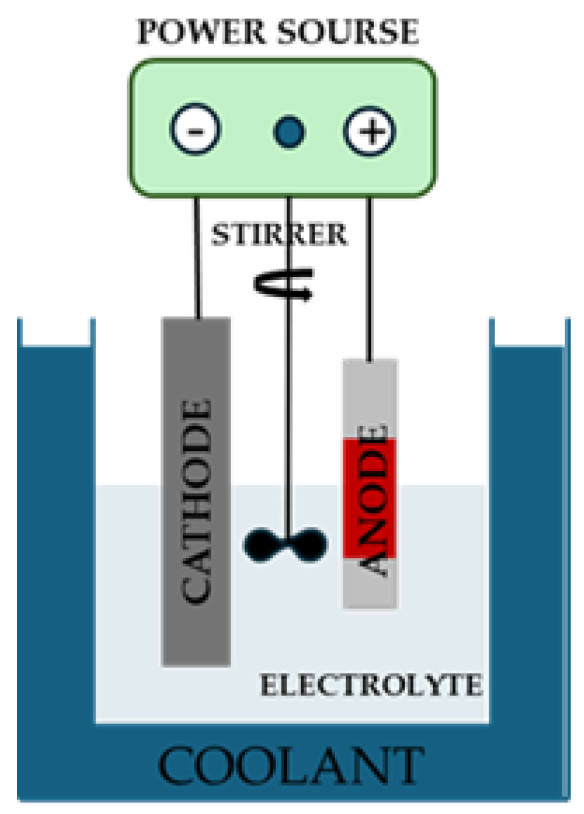
Figure 2.
Scheme of the structure of the specimens after the anodization, bio-inspired coating deposition and PLA application.
Figure 2.
Scheme of the structure of the specimens after the anodization, bio-inspired coating deposition and PLA application.
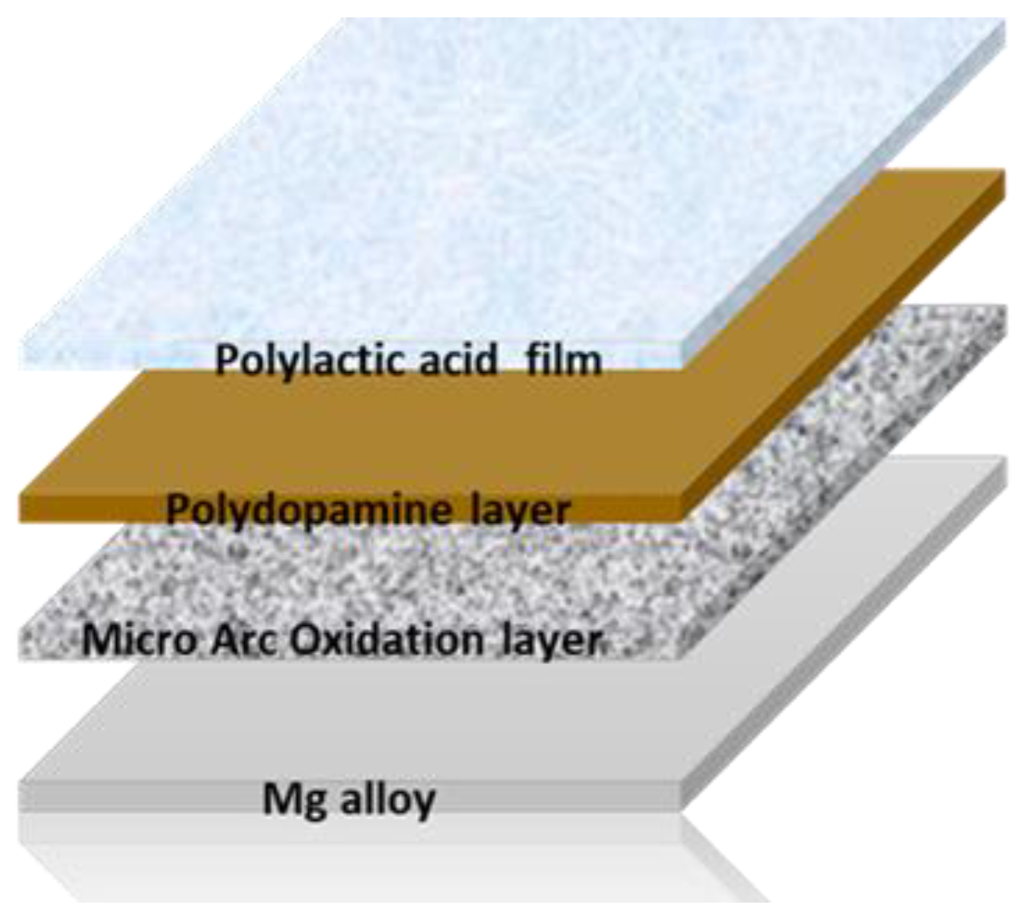
Figure 3.
Picture of specimens: untreated (a), after poly-dopamine layer deposition (b), after the anodization (c) and (d) after anodization and poly-dopamine layer deposition.
Figure 3.
Picture of specimens: untreated (a), after poly-dopamine layer deposition (b), after the anodization (c) and (d) after anodization and poly-dopamine layer deposition.
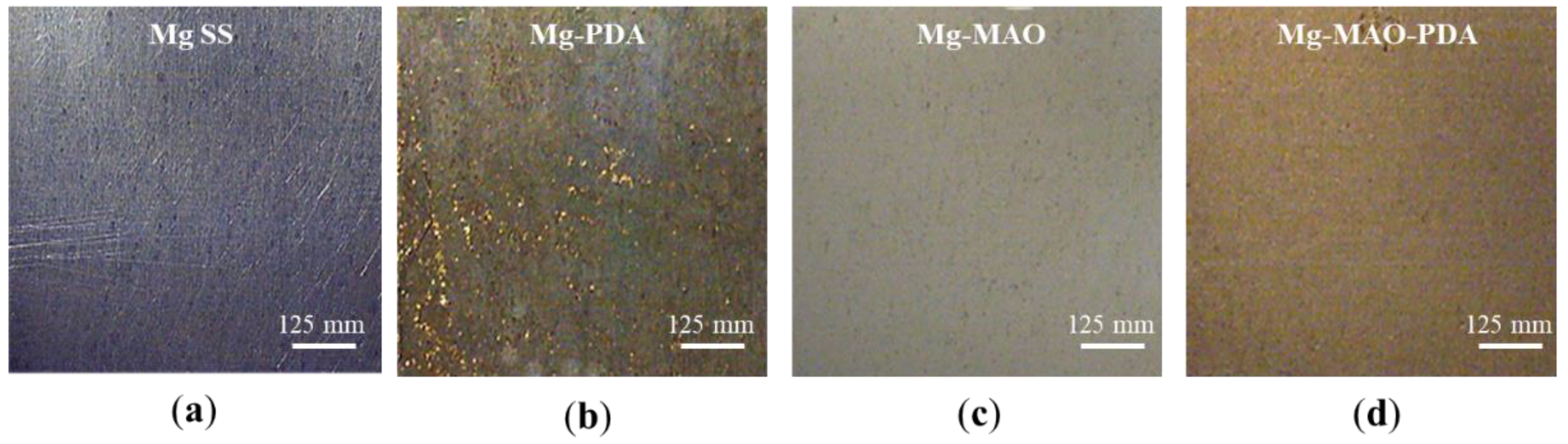
Figure 4.
SEM observations of specimens: untreated (a), after polydopamine layer deposition (b), after the anodization (c) and (d) after anodization and polydopamine layer deposition.
Figure 4.
SEM observations of specimens: untreated (a), after polydopamine layer deposition (b), after the anodization (c) and (d) after anodization and polydopamine layer deposition.
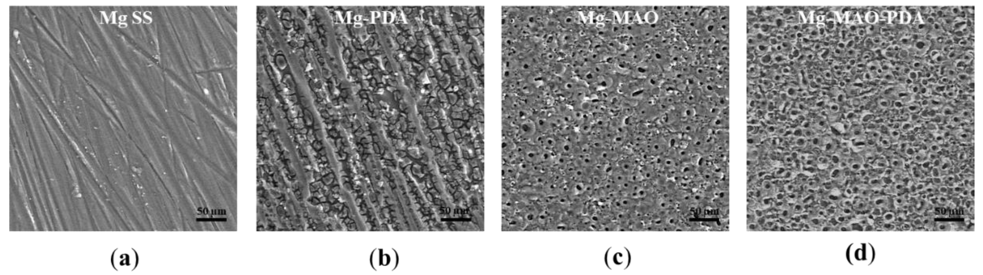
Figure 5.
SEM cross-section view of specimen after the micro-arc oxidation (MAO) treatment.
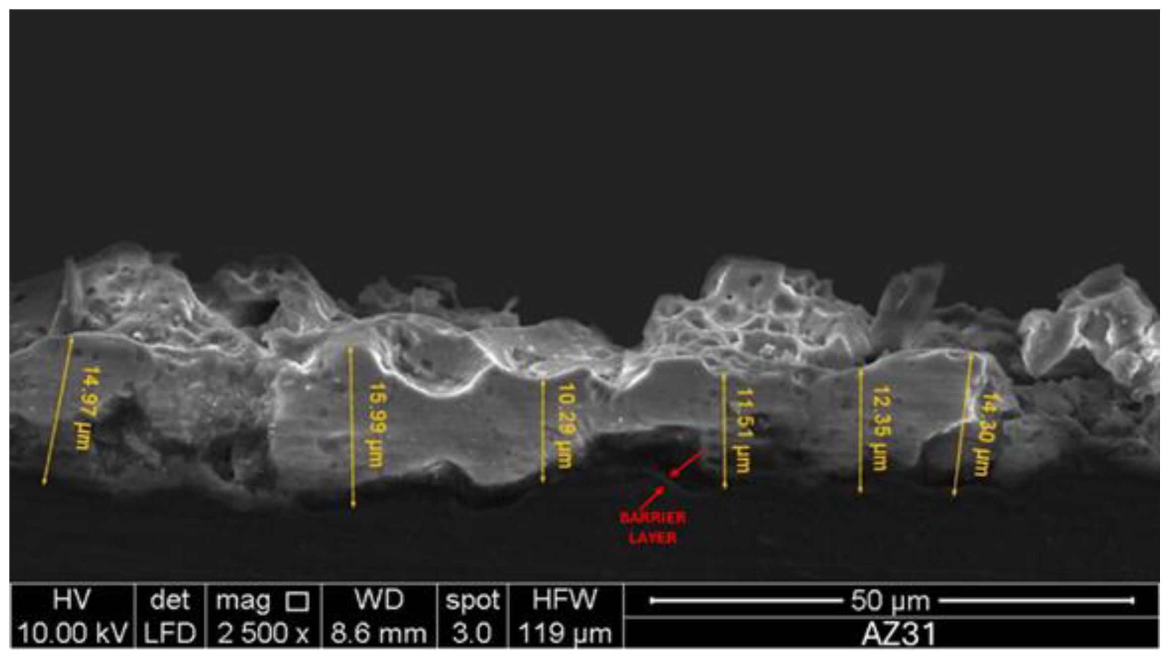
Figure 6.
EDS spectra of specimens: untreated (a), after polydopamine layer deposition (b), after the anodization (c) and (d) after anodization and polydopamine layer deposition.
Figure 6.
EDS spectra of specimens: untreated (a), after polydopamine layer deposition (b), after the anodization (c) and (d) after anodization and polydopamine layer deposition.
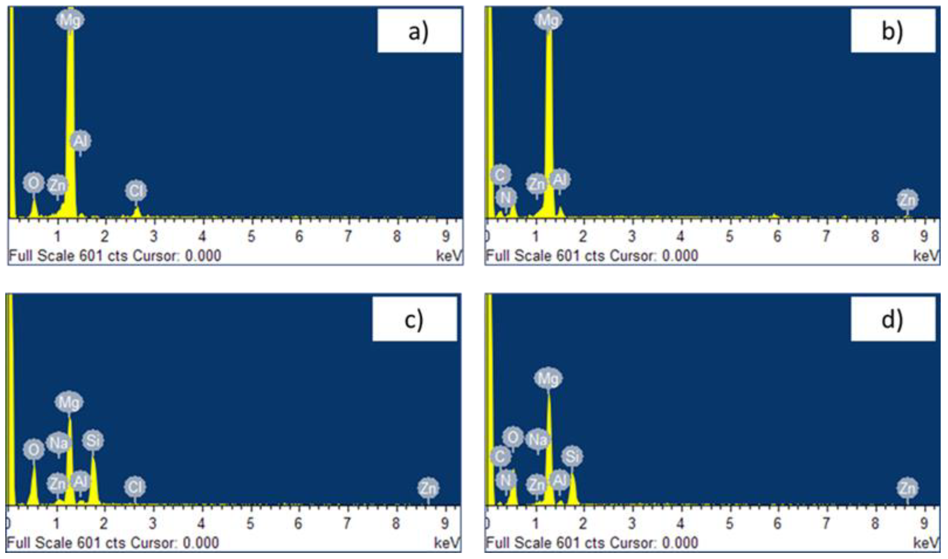
Figure 7.
SEM cross-section view of specimen after the micro-arc oxidation treatment, polydopamine deposition and PLA hot pressing.
Figure 7.
SEM cross-section view of specimen after the micro-arc oxidation treatment, polydopamine deposition and PLA hot pressing.
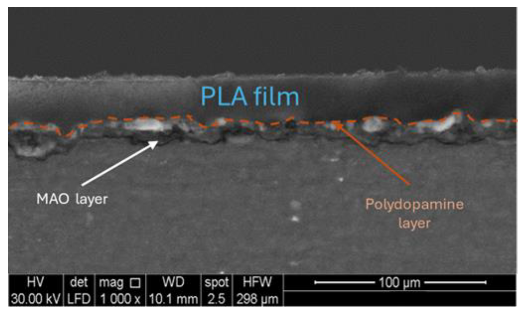
Figure 8.
XRD spectra of untreated and anodized samples.
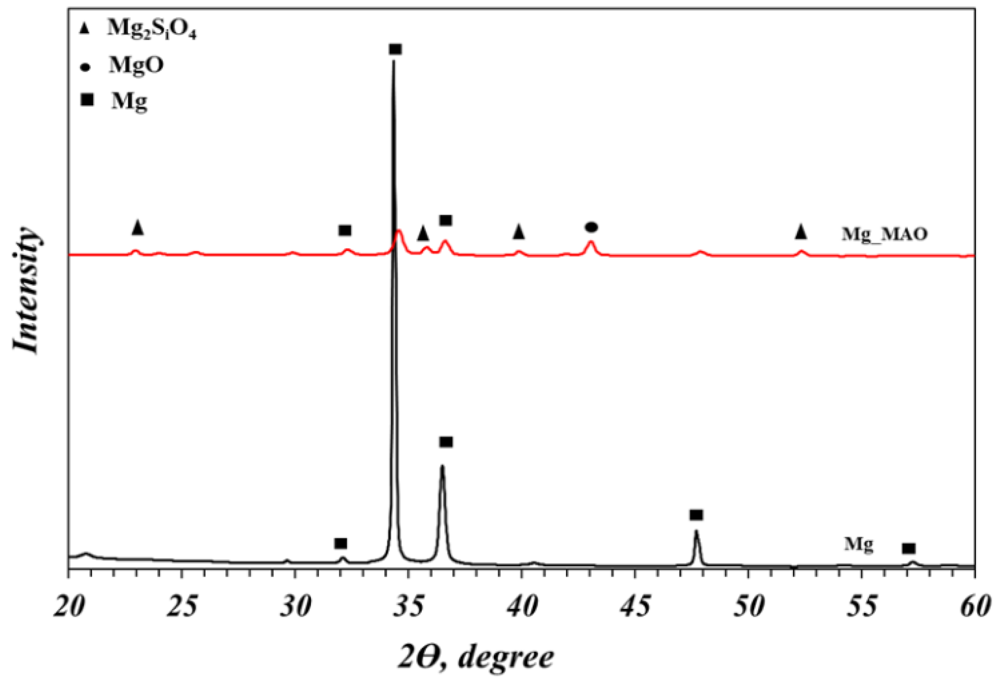
Figure 9.
Diagram of micro-harness measurements results obtained on magnesium substrate and on anodized specimen.
Figure 9.
Diagram of micro-harness measurements results obtained on magnesium substrate and on anodized specimen.
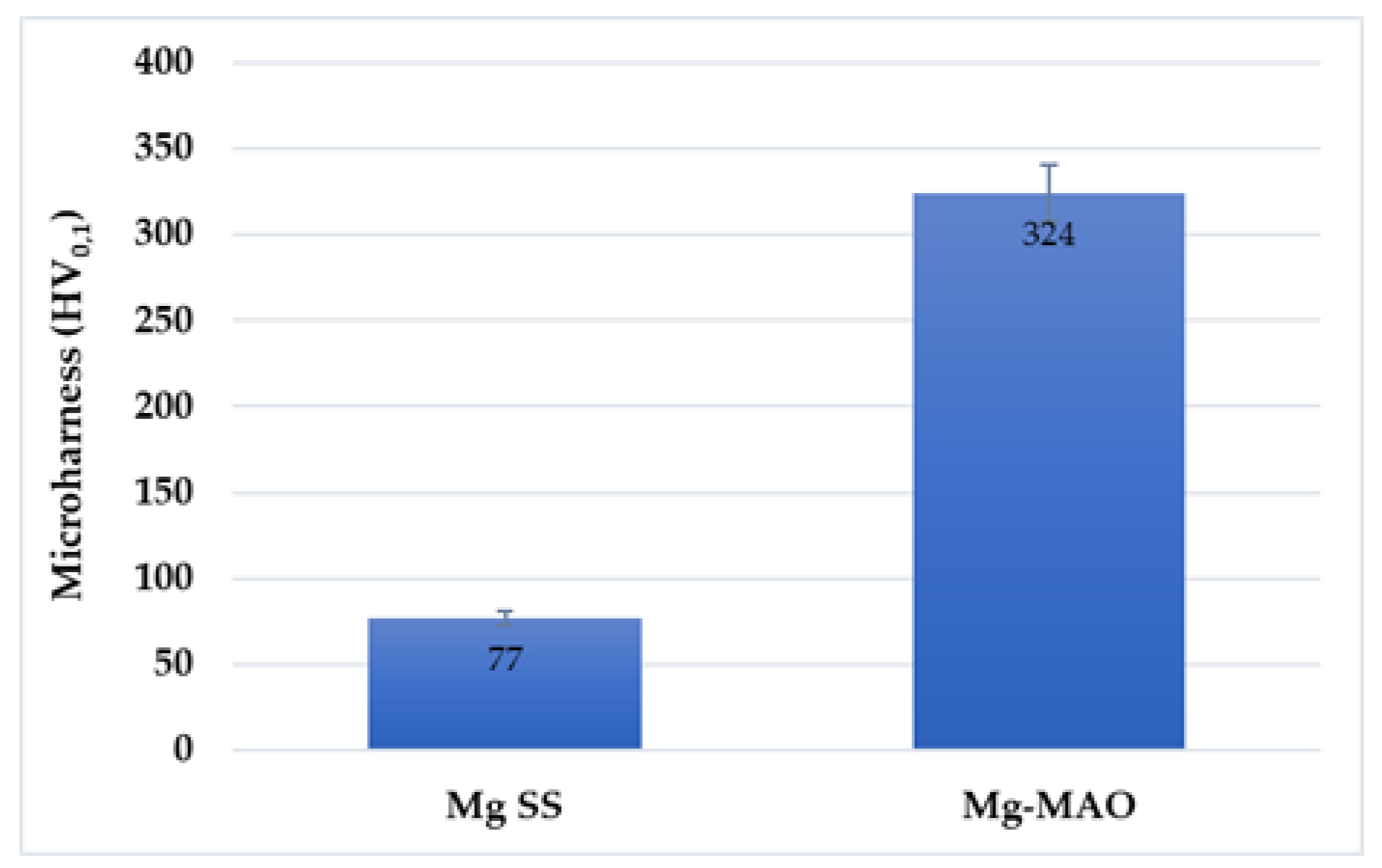
Figure 10.
3D roughness graphs obtained through the confocal laser scanning microscopy of specimens: untreated (a), after polydopamine layer deposition (b), after the anodization (c) and (d) after anodization and polydopamine layer deposition.
Figure 10.
3D roughness graphs obtained through the confocal laser scanning microscopy of specimens: untreated (a), after polydopamine layer deposition (b), after the anodization (c) and (d) after anodization and polydopamine layer deposition.
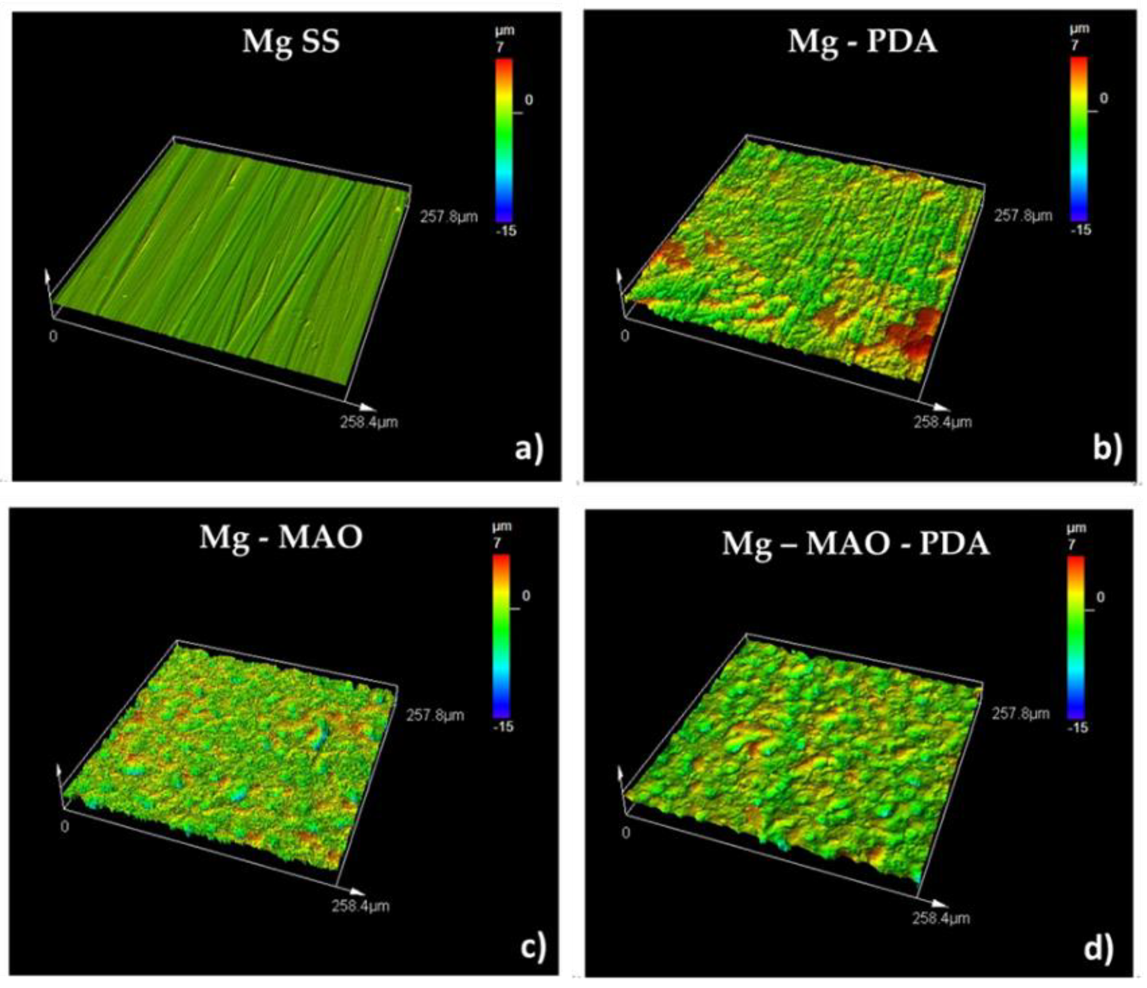
Figure 11.
3D graph of Mg-MAO-PDA-PLA specimen obtained through the confocal laser scanning microscopy.
Figure 11.
3D graph of Mg-MAO-PDA-PLA specimen obtained through the confocal laser scanning microscopy.
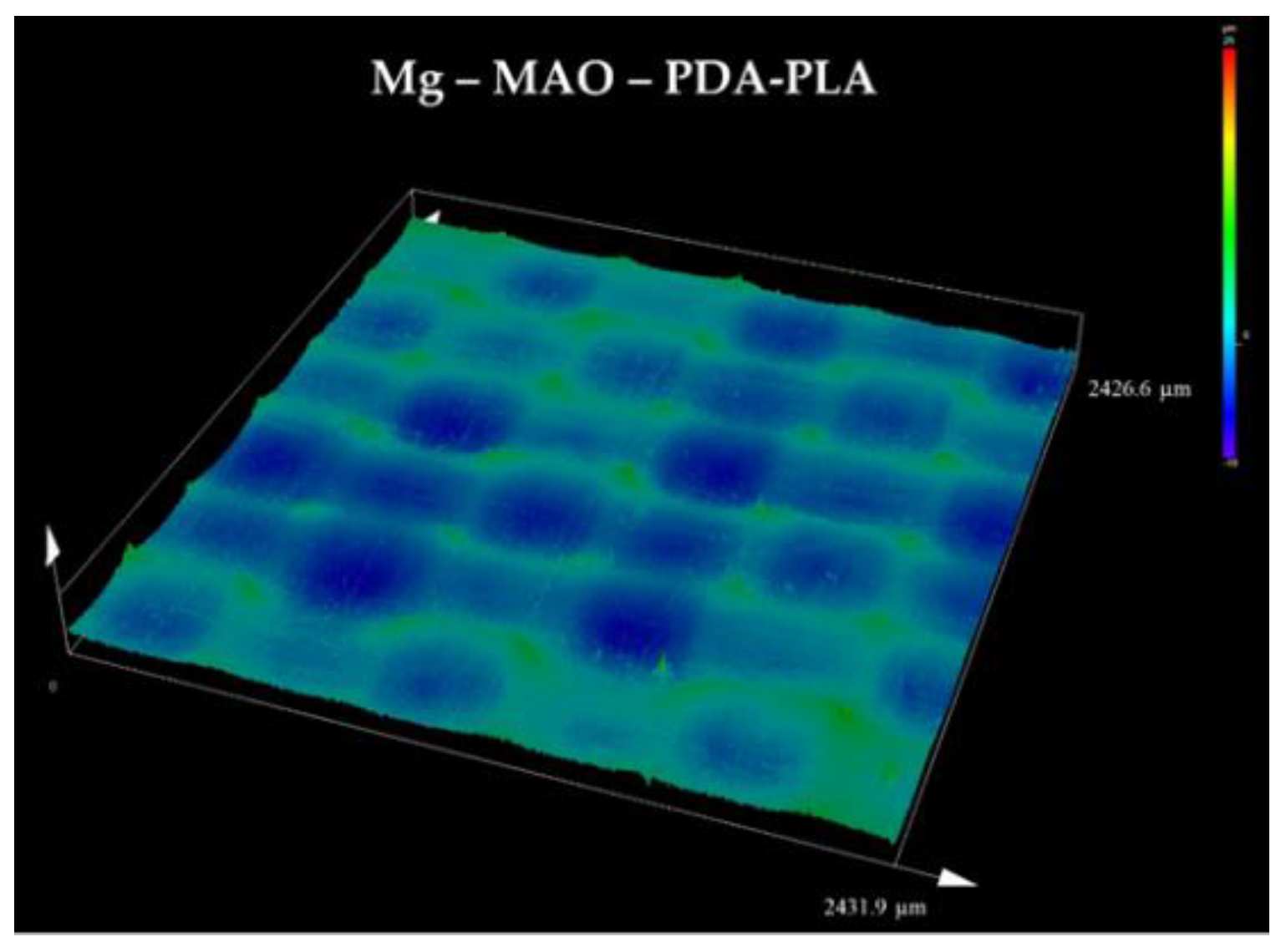
Figure 12.
(a) Horizontal and (b) vertical profile extracted from the 3D graph above reported.
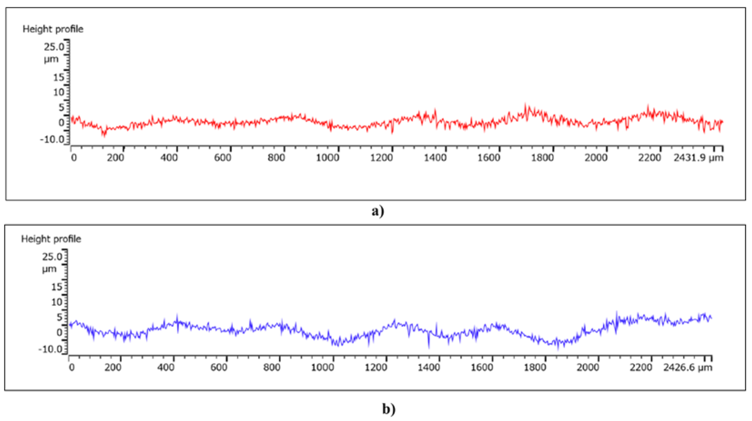
Figure 13.
Potentiodynamic polarization scans of specimens obtained by immersion in the solution of Hanks at 37 °C considering (a) geometrical area and (b) effective area.
Figure 13.
Potentiodynamic polarization scans of specimens obtained by immersion in the solution of Hanks at 37 °C considering (a) geometrical area and (b) effective area.
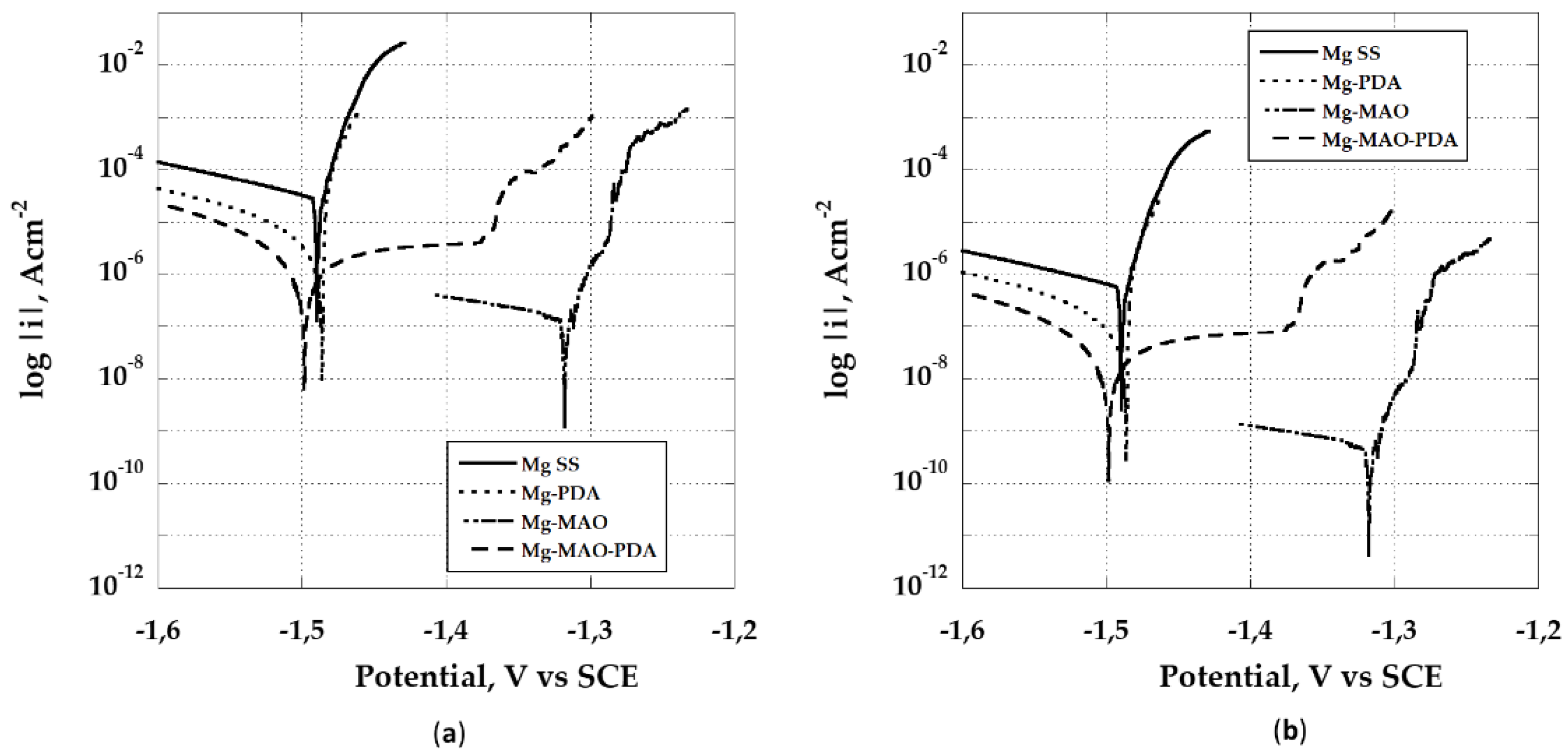
Figure 14.
Bode plots as (a) log |Z| and (b) phase angle of specimens recorded at the beginning of the immersion in the solution of Hanks at 37 °C.
Figure 14.
Bode plots as (a) log |Z| and (b) phase angle of specimens recorded at the beginning of the immersion in the solution of Hanks at 37 °C.

Figure 15.
Bode plots as (a) log |Z| and (b) phase angle of specimens recorded after 168h of the immersion in the solution of Hanks at 37 °C.
Figure 15.
Bode plots as (a) log |Z| and (b) phase angle of specimens recorded after 168h of the immersion in the solution of Hanks at 37 °C.
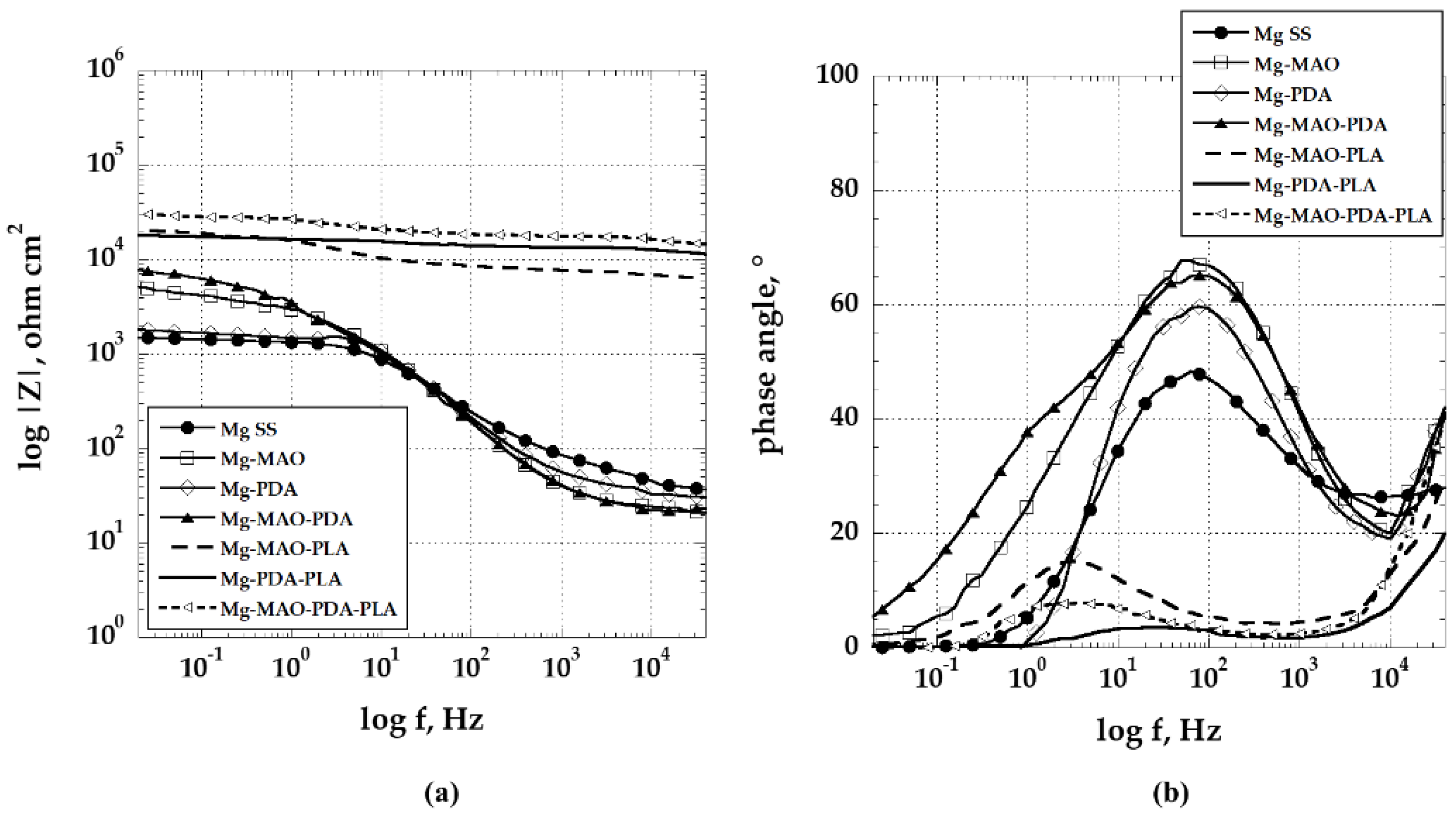
Figure 16.
Surface appearance of specimen at the end of the EIS measurements conducted for 168h in the solution of Hanks at 37 °C.
Figure 16.
Surface appearance of specimen at the end of the EIS measurements conducted for 168h in the solution of Hanks at 37 °C.
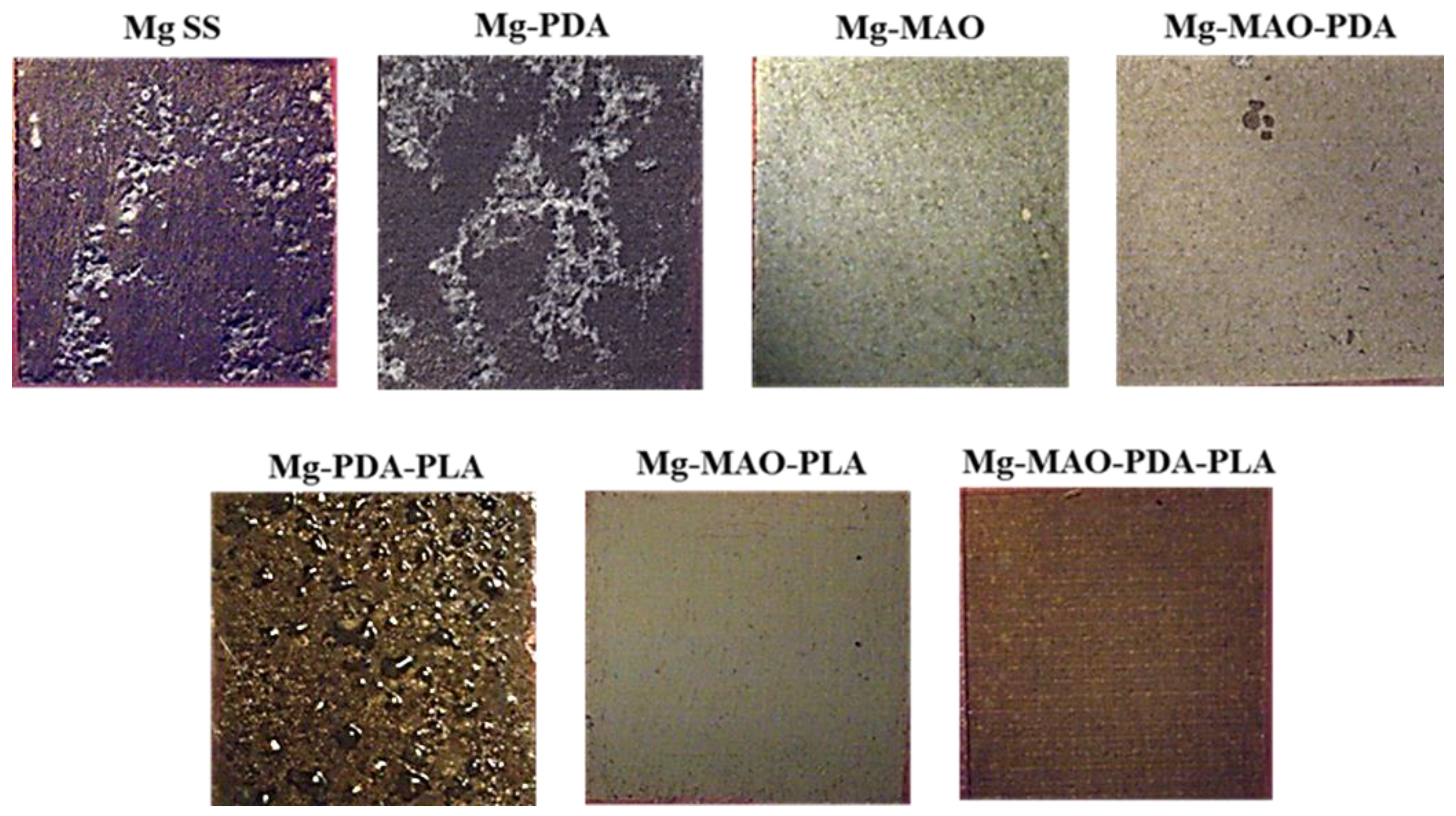

Table 1.
Average surface roughness parameters evaluated by means of laser confocal scanning microscope acquisitions.
Table 1.
Average surface roughness parameters evaluated by means of laser confocal scanning microscope acquisitions.
| Sa (µm) | Sq (µm) | Sp (µm) | Sv (µm) | Sku | Ssk | Sdq | Sdr (%) | |
|---|---|---|---|---|---|---|---|---|
| Mg SS | 0.3±0.05 | 0.3±0.02 | 3.1±0.4 | 1.2±0.43 | 4.4±0.2 | 0.1±0.03 | 0.2±0.01 | 2.1±0.05 |
| Mg - MAO | 1.7±0.2 | 2.4±0.1 | 8.0±0.2 | 14.7±1.3 | 6.4±0.4 | -1.4±0.02 | 4.7±0.05 | 289.7±12 |
| Mg - PDA | 1.3±0.3 | 1.7±0.3 | 7.1±0.3 | 5.8±0.2 | 3.7±0.2 | 0.5±0.01 | 1.2±0.02 | 39.7±2.1 |
| Mg- MAO-PDA | 1.2±0.2 | 1.6±0.3 | 5.4±0.2 | 11.4±0.5 | 5.9±0.2 | -0.8±0.02 | 1.0±0.05 | 49.4±1.6 |
Disclaimer/Publisher’s Note: The statements, opinions and data contained in all publications are solely those of the individual author(s) and contributor(s) and not of MDPI and/or the editor(s). MDPI and/or the editor(s) disclaim responsibility for any injury to people or property resulting from any ideas, methods, instructions or products referred to in the content. |
© 2025 by the authors. Licensee MDPI, Basel, Switzerland. This article is an open access article distributed under the terms and conditions of the Creative Commons Attribution (CC BY) license (http://creativecommons.org/licenses/by/4.0/).
Copyright: This open access article is published under a Creative Commons CC BY 4.0 license, which permit the free download, distribution, and reuse, provided that the author and preprint are cited in any reuse.


