
Submitted:
20 June 2025
Posted:
20 June 2025
You are already at the latest version
Abstract
In this study, 3D Mg scaffolds were obtained by the spark plasma sintering (SPS), and a calcium phosphate coating was then obtained on the samples by the plasma electrolytic oxidation. A hybrid coating with vancomycin, zoledronic acid and menaquinone MK-7 was formed additionally to improve biocompatibility. The mechanical properties of the formed specimens were studied. According to XRF, SEM, EDS and OSP studies obtained scaffolds have developed morphology and contain hydroxyapatite as well as bioactive substances. Formation of coatings improves samples wettability as well as wear resistance. This makes them promising for use as a new generation of implantation materials. The results are important for the development of personalized implants with improved functional characteristics.
Keywords:
Magnesium alloy
; plasma electrolytic oxidation
; spark plasma sintering
; hydroxyapatite
; vancomycin
; menaquinone MK-7
; zoledronate
; polydopamine
1. Introduction
Currently, magnesium-based alloys are one of the most promising implantation materials in orthopedic applications due to their numerous advantages, including a low weight of the final product, a low cost of manufacturing, bioresorbability, and biocompatibility [1,2,3]. However, challenges still exist, such as inconsistencies between the implants and the anatomical features of patients, reduced cell adhesion to the implants, and implant-associated infections (IAIs). To address the first challenge, the spark plasma sintering (SPS) method can be utilized to create three-dimensional (3D) samples, allowing for personalized implants. This not only enhances the reliability of the products but also accelerates the recovery process [4]. Thus, previously the spark plasma sintering (SPS) method was successfully used for the synthesis of porous ceramic materials, including biocompatible frameworks [5] and corrosion-resistant implants [6], as well as for the novel synthesis of nano-Hap with controlled morphology [7]. This confirms the promise of using SPS for the development of the porous ceramics with controlled degradation in vivo.
Additionally, plasma electrolytic oxidation (PEO), a coating formation method based on creating plasma microdischarges followed by rapid cooling of the affected area, can help solve the issue of cell adhesion. As a result of the PEO process, a porous structure is formed, which helps to increase the surface area of contact between the implant and surrounding tissues. This has a positive impact on cell adhesion to the implant's surface [8].
Hydroxyapatite (HA), the main mineral component of bone tissue, contains calcium and phosphate ions, which accelerate the formation of callus. This makes HA an excellent synthetic material for replacing lost bone tissue [9]. One way to form HA on the PEO-coated surface is by adding specific substances to the electrolyte solution. According to literature, various modifications of the electrolyte can be used for the synthesis of compounds during the PEO process [10,11]. Calcium glycerophosphate (CaPO4C3H7O2) is often used to create HA-based coatings [12,13,14,15]. During oxidation, calcium glycerophosphate decomposes into calcium and phosphate ions, which then form calcium orthophosphate, the crystallization precursor of HA. The concentration of calcium glycerophosphate in the electrolyte significantly influences the HA content in the resulting coating layers.
To address the issue of IAIs, studies are being conducted to incorporate antibiotics into the porous structure of the coating [16]. Additionally, it is possible to create heterolayered structures that facilitate the gradual release of drugs with osteogenic (menaquinone-7, MK-7) [17,18], antibacterial (vancomycin) [19], and antitumor (zoledronate) properties [20,21]. To ensure a controlled, layered release of these substances, it is proposed to develop hybrid polymer-containing layers using polydopamine (PDA). Due to its excellent biocompatibility, ease of polymerization, anti-inflammatory properties, and ability to promote HA deposition, PDA is widely used for forming implant surface coatings and creating nanomaterials [22,23].
In summary, presented study aims to develop a new generation of implants that combine a wide range of critical properties and enable targeted drug delivery.
2. Materials and Methods
The synthesis of the matrices was performed using SPS by consolidating the powders on a SPS-515S unit (Dr. Sinter·LAB™, SPS Syntex Inc., Kyoto, Japan). To improve the biocompatibility of the resulting samples, a mixture powder of magnesium and calcium carbonate with a total mass of 2 g was used. The optimal mass fraction of CaCO₃ was 7 wt.% (of 0, 1, 2, 3, 5, 7, 10 wt.%). The powder consolidation was carried out using SPS at a temperature of 550°C, with a heating rate adjusted in stages, starting at 92°C/min and increasing to the desired temperature. The sample was held at the maximum temperature for 5 min, then cooled to room temperature over a period of 30 min, under a compression pressure of 30 MPa.
The resulting cylindrical matrix samples had a diameter of 17 mm and a height ranging from 5 to 10 mm. The samples were cut into four identical sectors, each with a height of approximately 5±1 mm, and degreased using acetone.
In this study, the mode of PEO was selected based on previous research into the creation of bioactive coatings on magnesium alloys [24]: a bipolar mode ensured the formation of not only α-Ca3(PO4)2 on the coating surface, which acts as a center for the crystallization of HA, but also directly HA. PEO was carried out in an electrolyte containing 25 g/L calcium glycerophosphate CaPO4C3H7O2, 5 g/L sodium fluoride NaF, and 7 g/L sodium metasilicate Na2SiO3. During the PEO, the voltage increased to 400 V at a sweep rate of 4 V/s to realize plasma microdischarges at the interface between the electrolyte / natural oxide film, which discharges are necessary for the formation of the PEO layer. The duration of the PEO process was 100 s. All samples were washed with distilled water, degreased with alcohol, and dried with warm air.
To form hybrid coatings, menaquinone-7, dopamine, vancomycin, and zoledronate were used at concentrations of 0.15 mg/mL, 3 mg/mL, 5 mg/mL, and 0.03 mg/mL, respectively. Prior to this, the sample with the PEO coating that had been previously formed was washed with 95% ethanol and then dried. Considering that menaquinone-7 is fat-soluble vitamin, it was then impregnated into the sample under vacuum conditions with 0.95 mbar pressure (Figure 1).
Next, a polymerization solution was prepared according to the protocol presented in our previous paper [25]. Dopamine, vancomycin, zoledronate were dissolved in the TRIS-HCl buffer (10 mM, pH 8.5) (Sigma-Aldrich, St. Louis, MO, USA) in concentrations of 3 mg/ml, 5 mg/ml and 0.03 mg/ml, respectively. Then, solution (5 ml per sample) and magnetic stir bars were placed in measuring glass cylinders with a volume of 30 ml. Each sample was placed in an individual cylinder so that it was completely immersed in a polymerization solution. Cylinders with samples were put on a magnetic stirrer at 200 rpm at room temperature. After 2 hours, the samples were carefully removed, washed with deionized water and dried in air (24±2) °C for 4-6 hours. The schematic illustration of samples’ preparation and their designation are presented in Figure 1 and Table 1 respectively.
The elemental composition of samples was determined using X-ray fluorescence analysis on an EDX-800HS energy dispersive spectrometer (Shimadzu, Kyoto, Japan).
An EVO 40 scanning electron microscope (SEM) (Carl Zeiss, Oberkochen, Germany) with an INCA X-act instrument (Oxford Instruments, Abingdon, UK) for energy dispersive spectroscopy (EDS) were used to study surface morphology and analyze the elemental composition of the samples. Before analysis, a thin layer (100 nm) of Cr was sprayed onto the samples.
The morphology and microrelief of the surface were analyzed using the OSP370 optical surface profiling technique, employing an instrument installed on a M370 workstation (Princeton Applied Research, Oak Ridge, USA). The scanning rate was 150 µm per second, with increments of 1 µm. Data analysis was conducted using Gwyddion 2.45 software (Department of Nanometrology, Czech Metrology Institute, Brno, Czech Republic). To quantify the surface roughness, three-dimensional parameters were employed, including Sa, Sq. Sa represents the arithmetic mean deviation from the surface, while Sq denotes the standard deviation from a reference plane.
The wettability of the obtained surface layers was measured by the sessile drop method on a DSA100 drop shape analyzer (Krüss, Hamburg, Germany). Simulated body fluid (SBF) was used as test liquid in addition to the distilled water. Contact angle calculation was carried out using the Young–Laplace method [26]. The surface free energy (SFE) was calculated by the Owens-Wendt-Rabel-Kaelble (OWRK) method [27]. For the determination of contact angle (CA), deionized water and CH2I2 were used since the surface tension of these two liquids was established with high accuracy [28]. The volume of the test liquid was 5 µl during all measurements. The value of the CA was registered after the drop stabilized on the surface for 30 s. SFE was calculated according to Equation 1:
where γs is a SFE of solid phase, superscript indexes d and p are dispersive (Van-der-Waals interaction) and polar (dipole-dipole interactions, hydrogen bonds) components of the SFE, respectively.
γsd and γsp were determined graphically from the linearized Owens equation [27], in which the intersection with the ordinate axis corresponds to the root of the dispersed components, and the slope of the straight line corresponds to the root of the polar components of the SFE of a solid phase (Equation 2).
where γl is a liquid surface tension, d and p indexes are a dispersed and polar component of the liquid surface tension, respectively.
The wear resistance of the formed coatings was measured at the TRB-S-DE unit (CSM Instruments, Peseux, Switzerland). Using this device, wear, friction coefficient, abrasion time and number of revolutions are measured. The tests were carried out at room temperature in dry friction mode at a sliding speed of 10 mm/s and a load of 5 N. A corundum ball (α-Al2O3) was used as a counterbody. Wear resistance was assessed with a track circumference of 5 mm and a number of revolutions of 150.
All the results were analyzed statistically and expressed as a mean ± standard deviation. For the calculated mathematical parameters, the error determined by the method of indirect measurements (considering the errors of the measured parameters). At least 5 samples were used for each experiment.
3. Results and Discussion
3.1. SPS Process Characterization
As a result of the SPS, the following dilatometric dependencies were obtained (Figure 2). All samples are characterized by a general compaction dynamic, which is determined by CaCO3, as shown in the Figure 2. Powder compaction occurs in stages due to mechanical and thermal deformations.
Stage 1 is common to all samples and represents the mechanical compaction of initial powder under pressing pressure. Stage 2 is influenced by thermal heating and is accompanied by thermal compaction. According to the curves, the initial sintering stage (beginning of bending) occurs at a temperature of approximately 100° C and reaches a plateau at 500 °C. Stage 3 represents a plateau during which there are no significant changes in material compaction.
A similar trend was observed in the relationship between the shrinkage rate and temperature (Figure 2d). The temperature range between 100 and 200 °С corresponds to the main stage of material compaction, accompanied by a significant shrinkage rate. The range between 200 and 550 °С is characterized by a gradual decrease in the shrinkage rate and a plateau in shrinkage. Based on these findings, it can be concluded that an increase in the CaCO3/Mg ratio leads to a reduction in the absolute amount of shrinkage in the material and a decrease in its rate of change.
3.2. Coatings Composition and Morphology
To check the composition and ratio of elements in quantity in the formed layers, X-ray fluorescence (XRF) was carried out. Due to this, it was possible to see the ratio of calcium and phosphorus in the composition of the coatings, which confirmed the formation of hydroxyapatite on the surface (Table 2).
Based on the results of XRF data, high levels of calcium were observed on the surface of hybrid coating, accounting for more than a quarter of the total element composition. This calcium is predominantly present in the form of hydroxyapatite [29]. However, an excess of phosphorus relative to calcium suggests the presence of other phosphate compounds such as magnesium-substituted hydroxyapatite and magnesium phosphate (Table 2). This, along with the presence of orthosilicate and magnesium oxide in the, explains the observed excess of magnesium [29]. The presence of orthosilicate is confirmed by the detection of silicon in the layer composition (Table 2). It should be noted that the analysis of hybrid coatings was challenging due to hardware limitations, which prevented the detection of elements with an atomic mass below 23. Carbon, nitrogen, oxygen, and chlorine, present in the organic components of the hybrid coatings, occur in such low concentrations that they are detected by the instrument with an error margin not exceeding 1%. However, in a previous study, samples with close surface composition were analyzed using Raman spectroscopy as well as X-ray photoelectron spectroscopy and IR-spectroscopy [29]. The results confirmed the successful incorporation of zoledronate, vancomycin, PDA, and menaquinone into the coating surface of the samples [29].
3.3. Coating Morphology
Next, the morphological characteristics of the resulting surface were investigated. This is an essential aspect in the development of bioactive coatings for medical implants. According to several studies [30,31], surfaces with a well-developed microstructure can improve cell adhesion. These investigations have identified the optimal surface roughness for implants, which falls within the Ra range of approximately 2.4–3.0 µm [32,33].
Samples obtained by the SPS method were treated with a weak carbonic acid solution before applying the PEO coating to remove calcium carbonate particles and achieve a more developed surface morphology. Based on the analysis of the collected data, there is a trend of increased surface roughness in the coating as the proportion of calcium carbonate in the sample material composition increases. For instance, a sample containing 5 wt.% calcium carbonate, after treatment with the etching solution, exhibits a more developed and visually distinct morphology compared to samples with lower carbonate content, as observed in the microstructure of the PEO-coated surface (Figure 3a–3e and Figure 3a'–3e').
Samples containing 7 wt.% calcium carbonate exhibit a relatively more developed surface with a large number of pores and irregularities (Figure 3f). Based on the observed porosity, which was superior to other samples (Figure 3), it was decided to conduct further studies based on samples with 7 wt.% calcium carbonate proportion.
Samples containing 10 wt.% calcium carbonate have an even more developed surface due to the presence of pores and irregularities resulting from etching (Figure 5g). It was expected that the coating formed on these samples would exhibit a more complex morphology compared to samples with 5 wt.% and 7 wt.% calcium carbonate. However, the resulting PEO coating has a smoother surface texture than those on samples with lower calcium carbonate content (Figure 3d', 3g'). This is likely due to the larger surface area of samples containing 10 wt.% calcium carbonate. Under the same coating formation conditions, a reduction in current density was observed, leading to fewer and less intense microdischarges, resulting in coatings with a less complex morphology.
The SPS-HYB sample does not visually differ from the SPS-PEO sample (Figure 3f’). The surface of the composite coating is not smooth and contains numerous irregularities, due to this, it has a positive effect on cell adhesion, as demonstrated in a previous study [29].
Evaluation of SEM image of the uncoated sample indicates the presence of an uneven surface on which calcium inclusions are clearly visible (highlighted by arrows, Figure 4). The presence of calcium in the sample will allow additionally increasing the rate of bone tissue regeneration during implant degradation.
Analysis of SEM images of the surface reveals that the base PEO coating on magnesium has a significant number of pores and other microdefects (Figure 4), caused by several factors. During the process, significant gas evolution occurs, and the breakdown zone rapidly cools to the electrolyte temperature as the plasma microdischarges weaken [34]. As a result, molten material solidifies at locations where powerful plasma discharges occur, forming pores. At first glance, the morphology of hybrid coatings appears similar to that of PEO coatings. However, a thin layer of polydopamine containing various bioactive components can be observed on the surface of hybrid-coated samples (Figure 4).
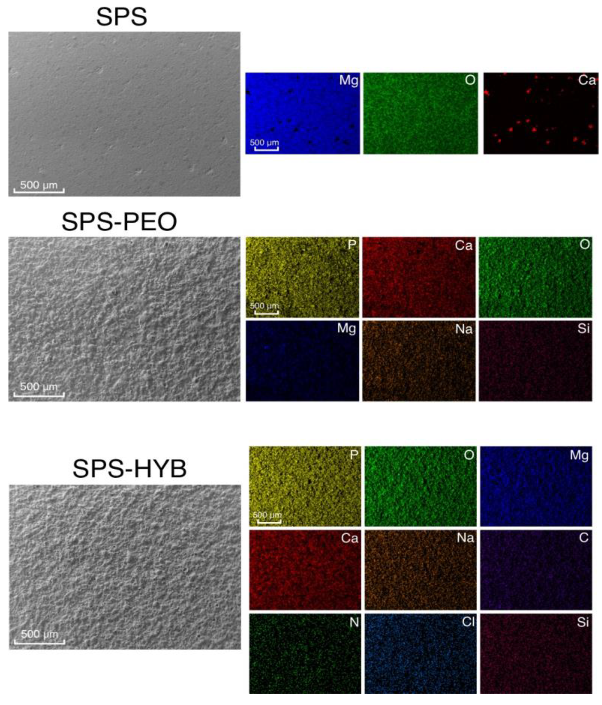
The EDS analysis is presented in Figure 5. For an uncoated sample, a high content of magnesium, oxygen, and calcium is observed, which are components of the powder material. On the surface of PEO-coated samples, elements present in both the sample and the electrolyte, such as magnesium, oxygen, sodium, calcium, and phosphorus, are evenly distributed. The hybrid coating SPS-HYB contains elements that are components of both the base PEO coating and the bioactive compounds (vancomycin, menaquinone-7, zoledronate, PDA). Taken together, this allows one to conclude that these compounds have been successfully incorporated into the surface layer.
Figure 5.
The results of EDS of bare SPS samples, with PEO and with hybrid coating.
The increase in surface roughness is caused by the formation of irregularities on the surface, which is a direct result of the coating formation process. After the plasma microdischarge ceases, a crater remains on the surface. The presence of CaCO₃ in the composition of the treated material leads to its degradation during PEO, which further increases the depths and heights of the surface topography. Additionally, there is an increase in both heights and depths by more than 3 times and 1.5 times, respectively, compared to the untreated surface (Table 3, Appendix A.1, A.2).
3.4. Coatings Wettability and Surface Free Energy
The obtained samples were also analyzed for surface wettability. The SPS sample exhibits hydrophobic properties, with a contact angle (CA) value of 123.8±3.1° (Figure 6). However, it demonstrates a relatively low surface free energy (SFE) of 12.9±1.7 mJ/m² (Figure 6, Table 4). The formation of PEO coatings leads to a significant increase in wettability, attributed to two factors. First, water adsorption on oxide surfaces is significantly higher than on metal surfaces [35]. Second, PEO coatings have a highly developed surface structure, increasing the contact area between the liquid and solid phases (Figure 4 and Figure 5) [36]. Additionally, the PEO layer has a well-developed porous structure, allowing droplets to penetrate deep into the coating [37]. As a result, the CA value on the SPS-PEO surface decreased by a factor of 20 (Figure 8), while the SFE value increased by a factor of 8 (Table 4, Figure 7).
The SPS-HYB sample showed values of CAs 26.9±4.1°, indicating moderate hydrophilicity due to the presence of a PDA film and water-soluble components, such as vancomycin and zoledronate, in the hybrid coating. This led to a slight decrease in SFE value to 76.6±3.2 mJ/m² (Figure 9, Table 4). The results confirm that the use of PEO coatings and hybrid layers significantly improves the wettability of surfaces, which is crucial for improving biocompatibility and cell adhesion in biomedical implants.
There are studies that present the dependence of cell adhesion and proliferation on the polar component of the SFE of implants [38,39]. Thus, in study [40], implants with a high polar component of SFE on their surface demonstrated the highest density of adherent cells, while those with a low polar component showed higher expression of inflammatory mediators and lower cell proliferation. Based on this information, it can be inferred that hybrid coatings on magnesium (SPS-HYB) possess the highest values for the polar component of SFE, as shown in Table 4. Consequently, cell adhesion to such surfaces would be significantly higher than to PEO-coated or uncoated samples.
The results obtained using deionized water are consistent with studies on the wettability of materials conducted using a simulated body fluid (SBF). SBF approximates human blood plasma in terms of ionic composition [29].
For uncoated samples, CAs values decrease by approximately three times, while for the SPS-PEO-treated sample, CAs values remain within the error (Figure 8). It should be noted that during the wettability investigation of uncoated samples, significant gas formation was observed upon contact with a droplet. This is explained by the low corrosion resistance of magnesium and the heterogeneity of its material structure, including the presence of individual grains, which caused the droplet to spread more rapidly.
For SPS-PEO and SPS-HYB, the CAs values remained unchanged and within the margin of experimental error (5.3±1.0° for PEO, and 21.0±4.2°, respectively) (Figure 8). This indicates that the coatings have optimal wettability and pronounced hydrophilic properties.
3.5. Coatings Mechanical Properties
The SPS-PEO samples exhibited a wear rate of (4.6±1.0)×10⁻² mm/(N m) (Table 5). This high wear can be attributed to the more developed microstructure of the SPS-PEO coating, influenced by the granular structure of the material, which consists of large, individual metal grains. Additionally, the presence of calcium inclusions in the PEO coating contributed to increased surface roughness and a more complex morphology. While these features enhance the structural complexity of the coating, they may also lead to the generation of microscopic debris during operation. Furthermore, the SPS samples exhibited brittleness under fracture loads, which is a significant drawback compared to cast metal. These results highlight the trade-offs between wear resistance, surface morphology, and mechanical durability in SPS-based materials with PEO coatings.
Note that the hybrid layers did not show any significant difference with the PEO layers and are not presented here.
4. Conclusions
In this study, 3D scaffolds with complex geometries and high specific surface area were developed. Samples with various types of grating structures and internal features were created. The SPS parameters were optimized, and magnesium samples were produced for further investigation. The samples were fabricated from powdered magnesium material with a controlled concentration of CaCO₃. A correlation was established between the proportion of CaCO₃ and MgO in the mixture and the reduction in the absolute shrinkage of the material. An optimal percentage of 7 wt.% CaCO₃ in the sintered material was identified.
By next step, hybrid coatings with menaquinone-7, zoledronate and vancomycin were created by polymerization of PDA on PEO-pretreated SPS-samples.
The composition of the resulting hybrid coatings was analyzed using XRF and EDS. The coatings contained calcium phosphate compounds, impregnated and polymerized materials, and other components. The structural features of the obtained implants were investigated using optical microscopy and SEM. Analysis of the roughness parameters of samples with PEO coatings using optical surface profilometry revealed an increase in roughness compared to the uncoated surface.
The wettability of the surface for the obtained hybrid coatings on magnesium samples was investigated, and surface energy was calculated to determine values that could positively influence cell adhesion and proliferation. All samples with hybrid coatings exhibited a decrease in contact angle and an increase in surface free energy compared to uncoated samples, a result of both the roughness of the PEO layer and the presence of a polydopamine film and water-soluble compounds within the coatings.
The results of mechanical testing revealed that SPS-PEO samples possess a unique microstructure characterized by increased surface roughness and complex morphology, driven by the granular structure of the material and the presence of calcium carbonate inclusions. However, the higher wear rate and brittleness under fracture loads highlight the need for further optimization to balance wear resistance, surface morphology, and mechanical durability. These findings open prospects for the development of materials with enhanced performance characteristics, while also emphasizing the importance of considering trade-offs between structural and mechanical properties.
Author Contributions
Conceptualization K.N. and D.M.; methodology E.B. and A.B.; validation K.N., O.S. and D.M.; formal analysis A.G., D.L., M.N., A.P. and E.P.; investigation E.B., I.I., A.B. and S.A.; data curation O.S. and S.A.; writing—original draft preparation A.G. M.G. and D.L.; writing—review and editing K.N., I.I., O.S., E.P.; visualization A.G., M.G. and A.P.; supervision K.N. and D.M.; project administration S.S. and S.G.; funding acquisition I.I. All authors have read and agreed to the published version of the manuscript.
Funding
The study was supported by the Russian Science Foundation grant no. 24-79-00098, https://rscf.ru/project/24-79-00098/.
Data Availability Statement
The data presented in this study are available on request from the corresponding author.
Conflicts of Interest
The authors declare no conflicts of interest.
Abbreviations
The following abbreviations are used in this manuscript:
| IAIs | Implant-associated infections |
| SPS | Spark plasma sintering |
| PEO | Plasma electrolytic oxidation |
| HA | Hydroxyapatite |
| MK-7 | Menaquinone-7 (Vitamin K2) |
| PDA | Polydopamine |
| HYB | Hybrid |
| XRF | X-ray fluorescence |
| SEM | Scanning electron microscopy |
| EDS | Energy dispersive spectroscopy |
| OSP | Optical surface profiling |
| SBF | Simulated body fluid |
| SFE | Surface free energy |
| OWRK | Owens-Wendt-Rabel-Kaelble method |
| CA | Contact angle |
| IR | Infrared Spectroscopy |
| XPS | X-ray photoelectron spectroscopy |
Appendix A
Appendix A.1
For initial samples with different calcium carbonate contents, the Sa and Sq parameters exhibit similar values. Upon analysis of the presented data, there is an increase in peak heights and valley depths, which is associated with an increase in the size and quantity of valleys (Figure A1).
Figure A1.
3D surface profiles for SPS samples with the following CaCO3 concentrations: a – 0 wt.%, b – 1 wt.%, c – 2 wt.%, d – 3 wt.%, e – 5 wt.%, – 7 wt.%, – 10 wt.%.
Figure A1.
3D surface profiles for SPS samples with the following CaCO3 concentrations: a – 0 wt.%, b – 1 wt.%, c – 2 wt.%, d – 3 wt.%, e – 5 wt.%, – 7 wt.%, – 10 wt.%.
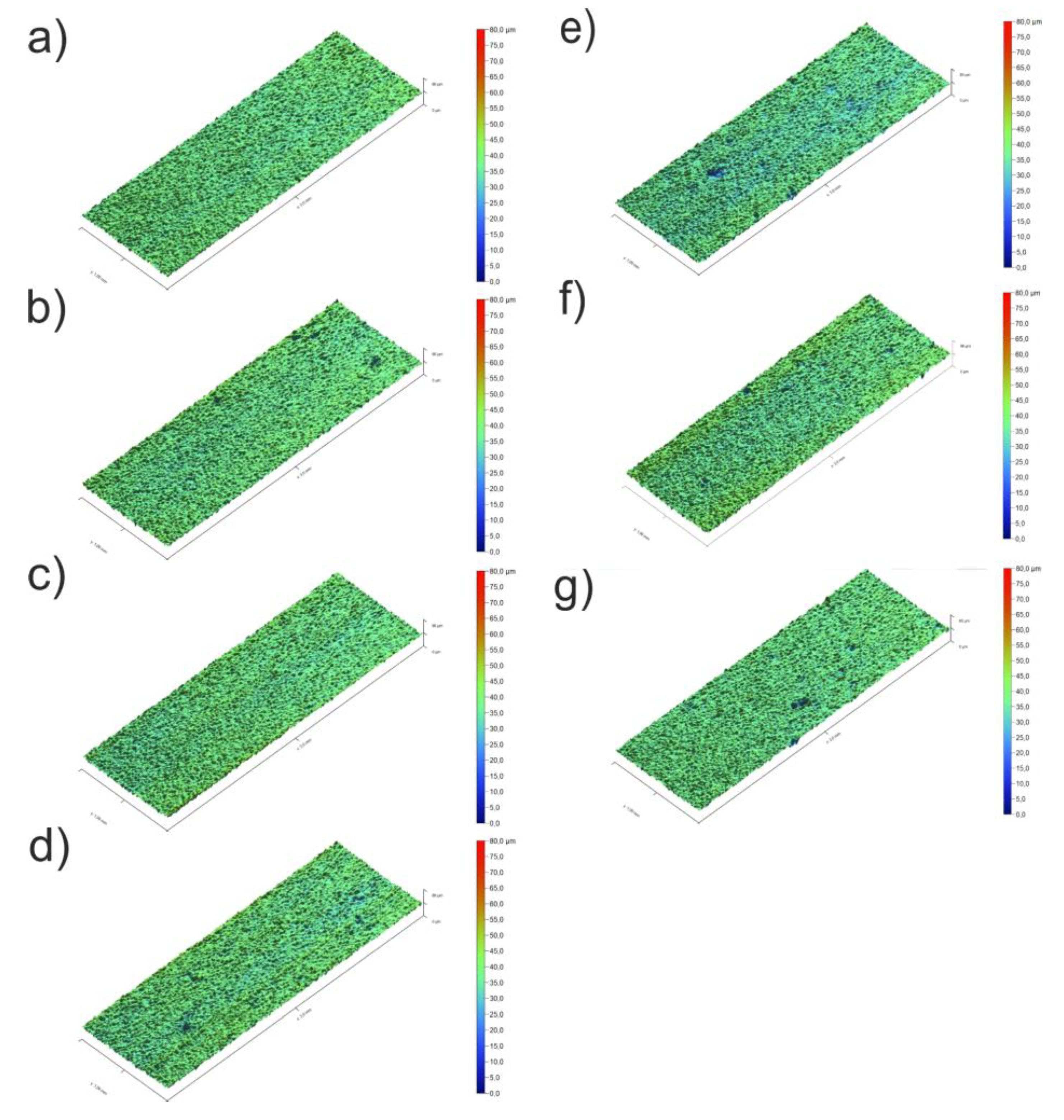
This behavior of the parameters is attributed to the etching of calcium carbonate during the surface preparation and standardization process. At the same time, the maximum depth value was observed at a concentration of 3% by weight (Figure A1).
Appendix A.2
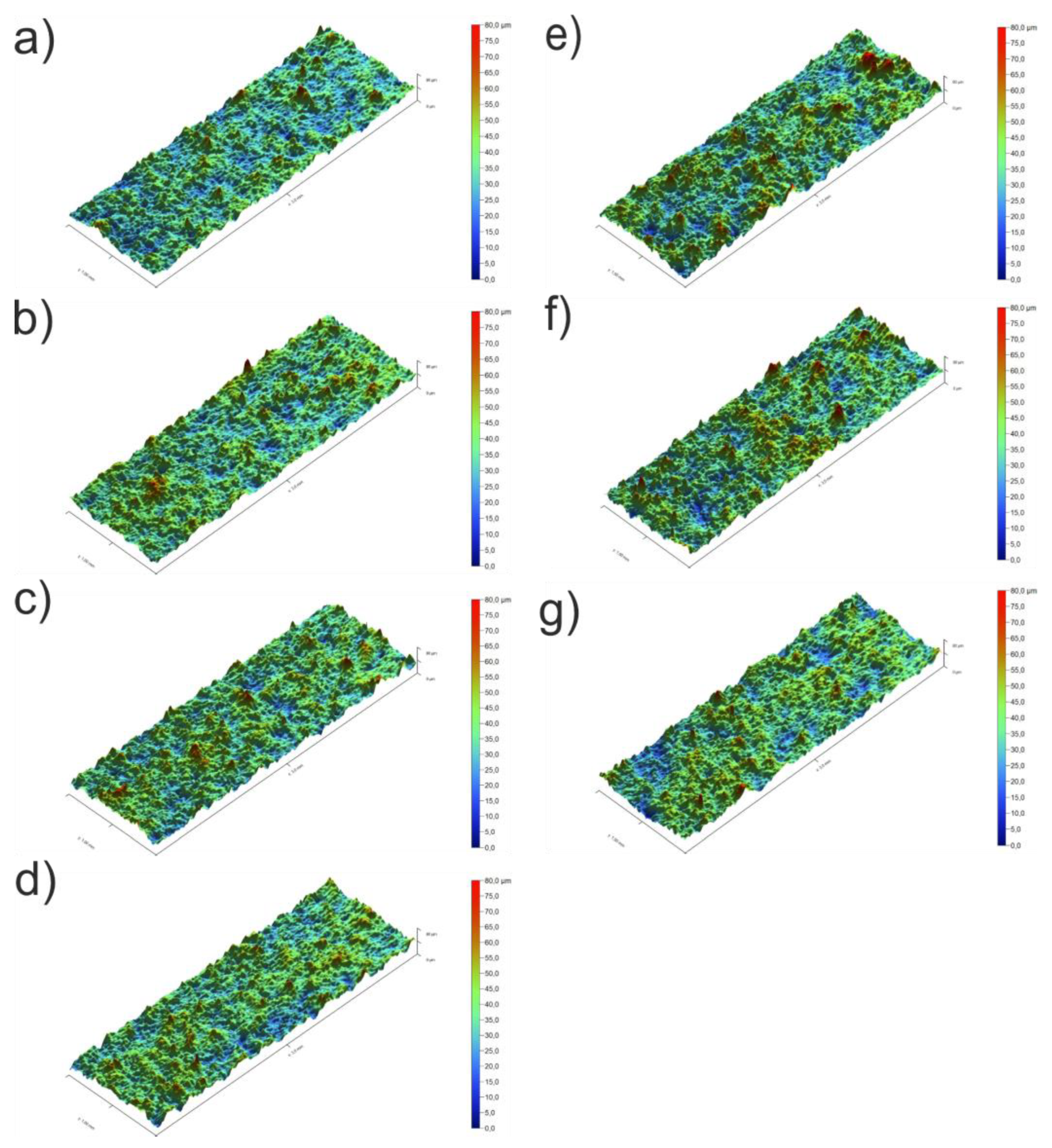
An analysis of the roughness parameters of the samples with PEO coatings indicates an increase in the surface roughness compared to the samples without coating (Figure A2).
Figure A2.
3D surface profiles of SPS-PEO samples with the following CaCO3 concentrations: a – 0 wt.%, b – 1 wt.%, c – 2 wt.%, d – 3 wt.%, e – 5 wt.%, f – 7 wt.%, g – 10 wt.%.
Figure A2.
3D surface profiles of SPS-PEO samples with the following CaCO3 concentrations: a – 0 wt.%, b – 1 wt.%, c – 2 wt.%, d – 3 wt.%, e – 5 wt.%, f – 7 wt.%, g – 10 wt.%.
References
- Staiger, M.P.; Pietak, A.M.; Huadmai, J.; Dias, G. Magnesium and Its Alloys as Orthopedic Biomaterials: A Review. Biomaterials 2006, 27, 1728–1734. [Google Scholar] [CrossRef] [PubMed]
- Jing, Z.; Ni, R.; Wang, J.; Lin, X.; Fan, D.; Wei, Q.; Zhang, T.; Zheng, Y.; Cai, H.; Liu, Z. Practical Strategy to Construct Anti-Osteosarcoma Bone Substitutes by Loading Cisplatin into 3D-Printed Titanium Alloy Implants Using a Thermosensitive Hydrogel. Bioact. Mater. 2021, 6, 4542–4557. [Google Scholar] [CrossRef] [PubMed]
- Gu, X.N.; Xie, X.H.; Li, N.; Zheng, Y.F.; Qin, L. In Vitro and in Vivo Studies on a Mg–Sr Binary Alloy System Developed as a New Kind of Biodegradable Metal. Acta Biomater. 2012, 8, 2360–2374. [Google Scholar] [CrossRef]
- Guzzi, E.A.; Tibbitt, M.W. Additive Manufacturing of Precision Biomaterials. Adv. Mater. 2019, 32. [Google Scholar] [CrossRef] [PubMed]
- Papynov, E.K. , Mayorov V.Yu., Portnyagin A.S., Shichalin O.O., Kobylyakov S.P., Kaidalova T.A., Nepomnyashiy A.V., Sokol׳nitskaya T.A., Zub Yu.L., Avramenko V.A. Application of carbonaceous template for porous structure control of ceramic composites based on synthetic wollastonite obtained via Spark Plasma Sintering. Ceram. Int. 2015, 41, 1171–1176. [Google Scholar]
- Papynov, E.K. , Shichalin O.O., Apanasevich V.I., Afonin I.S., Evdokimov I.O., Mayorov V.Yu., Portnyagin A.S., Agafonova I.G., Skurikhina Yu.E., Medkov M.A. Synthetic CaSiO3 sol-gel powder and SPS ceramic derivatives: “In vivo” toxicity assessment. Prog. Nat. Sci.: Mat. Int. 2019, 29, 569–575. [Google Scholar] [CrossRef]
- Papynov, E.K. , Shichalin O.O., Apanasevich V.I., Portnyagin A.S., Mayorov V.Yu, Buravlev I.Yu, Merkulov E.B., Kaidalova T.A., Modin E.B., Afonin I.S., Evdokimov I.O., Geltser B.I., Zinoviev S.V., Stepanyugina A.K., Kotciurbii E.A., Bardin A.A., Korshunova O.V. Sol-gel (template) synthesis of osteoplastic CaSiO3/HAp powder biocomposite: “In vitro” and “in vivo” biocompatibility assessment. Powd. Tech. 2020, 367, 762–773. [Google Scholar] [CrossRef]
- Ghanbari, A.; Bordbar-Khiabani, A.; Warchomicka, F.; Sommitsch, C.; Yarmand, B.; Zamanian, A. PEO/Polymer Hybrid Coatings on Magnesium Alloy to Improve Biodegradation and Biocompatibility Properties. Surf. Interfaces. 2023, 36, 102495. [Google Scholar] [CrossRef]
- Lin, K.; Chang, J. Structure and Properties of Hydroxyapatite for Biomedical Applications. In Hydroxyapatite (Hap) for Biomedical Applications; Elsevier, 2015; pp. 3–19.
- Zehra, T.; Patil, S.A.; Shrestha, N.K.; Fattah-alhosseini, A.; Kaseem, M. Anionic Assisted Incorporation of WO3 Nanoparticles for Enhanced Electrochemical Properties of AZ31 Mg Alloy Coated via Plasma Electrolytic Oxidation. J. Alloys Compd. 2022, 916, 165445. [Google Scholar] [CrossRef]
- Arrabal, R.; Matykina, E.; Viejo, F.; Skeldon, P.; Thompson, G.E.; Merino, M.C. AC Plasma Electrolytic Oxidation of Magnesium with Zirconia Nanoparticles. Appl. Surf. Sci. 2008, 254, 6937–6942. [Google Scholar] [CrossRef]
- Daroonparvar, M.; Yajid, M.A.M.; Yusof, N.M.; Bakhsheshi-Rad, H.R.; Hamzah, E.; Mardanikivi, T. Deposition of Duplex MAO Layer/Nanostructured Titanium Dioxide Composite Coatings on Mg–1%Ca Alloy Using a Combined Technique of Air Plasma Spraying and Micro Arc Oxidation. J. Alloys Compd. 2015, 649, 591–605. [Google Scholar] [CrossRef]
- Kaseem, M.; Fatimah, S.; Nashrah, N.; Ko, Y.G. Recent Progress in Surface Modification of Metals Coated by Plasma Electrolytic Oxidation: Principle, Structure, and Performance. Prog. Mater. Sci. 2021, 117, 100735. [Google Scholar] [CrossRef]
- Mashtalyar, D.V.; Nadaraia, K.V.; Plekhova, N.G.; Imshinetskiy, I.M.; Piatkova, M.A.; Pleshkova, A.I.; Kislova, S.E.; Sinebryukhov, S.L.; Gnedenkov, S.V. Antibacterial Ca/P-Coatings Formed on Mg Alloy Using Plasma Electrolytic Oxidation and Antibiotic Impregnation. Mater. Lett. 2022, 317, 132099. [Google Scholar] [CrossRef]
- Venkateswarlu, B.; Sunil, B.R.; Kumar, R.S. Magnesium Based Alloys and Composites: Revolutionized Biodegradable Temporary Implants and Strategies to Enhance Their Performance. Materialia 2023, 27, 101680. [Google Scholar] [CrossRef]
- Chai, F.; Hornez, J.-C.; Blanchemain, N.; Neut, C.; Descamps, M.; Hildebrand, H.F. Antibacterial Activation of Hydroxyapatite (HA) with Controlled Porosity by Different Antibiotics. Biomol. Eng. 2007, 24, 510–514. [Google Scholar] [CrossRef]
- Akbulut, A.C.; Wasilewski, G.B.; Rapp, N.; Forin, F.; Singer, H.; Czogalla-Nitsche, K.J.; Schurgers, L.J. Menaquinone-7 Supplementation Improves Osteogenesis in Pluripotent Stem Cell Derived Mesenchymal Stem Cells. Front. cell dev. biol. 2021, 8. [Google Scholar] [CrossRef]
- Wang, Y.; Yang, W.; Liu, L.; Liu, L.; Chen, J.; Duan, L.; Li, Y.; Li, S. Vitamin K2 (MK-7) Attenuates LPS-Induced Acute Lung Injury via Inhibiting Inflammation, Apoptosis, and Ferroptosis. PLOS ONE 2023, 18, e0294763. [Google Scholar] [CrossRef]
- Helms, S.M.; O’Neill, L.; Behbahani, S.B.; Tzeng, J.; Jeray, K.; Kennedy, M.S.; Cross, A.W.; Tanner, S.L.; DesJardins, J.D. Efficacy of a Plasma-Deposited, Vancomycin/Chitosan Antibiotic Coating for Orthopaedic Devices in a Bacterially Challenged Rabbit Model. Materialia 2021, 17, 101122. [Google Scholar] [CrossRef]
- Grey, A.; Horne, A.; Gamble, G.; Mihov, B.; Reid, I.R.; Bolland, M. Ten Years of Very Infrequent Zoledronate Therapy in Older Women: An Open-Label Extension of a Randomized Trial. J Clin Endocrinol Metab. 2020, 105, e1641–e1647. [Google Scholar] [CrossRef]
- Qian, J.; Qin, H.; Zeng, P.; Hou, J.; Mo, X.; Shen, G.; Zeng, H.; Zhang, W.; Chen, Y.; Wan, G. Metal-Organic Zn-Zoledronic Acid and 1-Hydroxyethylidene-1,1-Diphosphonic Acid Nanostick-Mediated Zinc Phosphate Hybrid Coating on Biodegradable Zn for Osteoporotic Fracture Healing Implants. Acta Biomater. 2023, 166, 685–704. [Google Scholar] [CrossRef]
- Liu, X.; Chen, W.; Shao, B.; Zhang, X.; Wang, Y.; Zhang, S.; Wu, W. Mussel Patterned with 4D Biodegrading Elastomer Durably Recruits Regenerative Macrophages to Promote Regeneration of Craniofacial Bone. Biomaterials 2021, 276, 120998. [Google Scholar] [CrossRef] [PubMed]
- Li, Y.; Yang, L.; Hou, Y.; Zhang, Z.; Chen, M.; Wang, M.; Liu, J.; Wang, J.; Zhao, Z.; Xie, C.; et al. Polydopamine-Mediated Graphene Oxide and Nanohydroxyapatite-Incorporated Conductive Scaffold with an Immunomodulatory Ability Accelerates Periodontal Bone Regeneration in Diabetes. Bioact. Mater. 2022, 18, 213–227. [Google Scholar] [CrossRef] [PubMed]
- Barati Darband, Gh.; Aliofkhazraei, M.; Hamghalam, P.; Valizade, N. Plasma Electrolytic Oxidation of Magnesium and Its Alloys: Mechanism, Properties and Applications. J. Magnes. Alloy 2017, 5, 74–132. [Google Scholar] [CrossRef]
- Mashtalyar, D. V.; Imshinetskiy, I. M.; Kashepa, V. V.; Nadaraia, K. V.; Piatkova, M. A.; Pleshkova, A. I.; Fomenko, K. A.; Ustinov, A. Yu; Sinebryukhov, S. L.; Gnedenkov, S. V. Effect of Ta2O5 nanoparticles on bioactivity, composition, structure, in vitro and in vivo behavior of PEO coatings on Mg-alloy. J. Magnes. Alloy 2024, 12, 2360–2379. [Google Scholar] [CrossRef]
- Finn, R. The Contact Angle in Capillarity. Physics of Fluids 2006, 18. [Google Scholar] [CrossRef]
- Owens, D.K.; Wendt, R.C. Estimation of the Surface Free Energy of Polymers. J. Appl. Polym. Sci. 1969, 13, 1741–1747. [Google Scholar] [CrossRef]
- Jasper, J.J. The Surface Tension of Pure Liquid Compounds. J. Phys. Chem. Ref. Data 1972, 1, 841–1010. [Google Scholar] [CrossRef]
- Piatkova, M.A.; Nadaraia, K.V.; Ponomarenko, A.; Manzhulo, I.; Gerasimenko, M.S.; Pleshkova, A.I.; Belov, E.A.; Imshinetskiy, I.M.; Fomenko, K.; Osmushko, I.; et al. Hybrid Surface Layers with Antibacterial and Anti-Inflammatory Activity for Implants Materials. J. Magnes. Alloy 2025. [CrossRef]
- Pérez Zapata, K.; Lenis, J.A.; Rico, P.; Ribelles, J.L.G.; Bolívar, F.J. Determination of Synergistic Effect between Roughness and Surface Chemistry on Cell Adhesion of a Multilayer Si - Hydroxyapatite Coating on Ti6Al4V Obtained by Magnetron Sputtering. Thin Solid Films 2022, 760, 139489. [Google Scholar] [CrossRef]
- Lerebours, A.; Vigneron, P.; Bouvier, S.; Rassineux, A.; Bigerelle, M.; Egles, C. Additive Manufacturing Process Creates Local Surface Roughness Modifications Leading to Variation in Cell Adhesion on Multifaceted TiAl6V4 Samples. Bioprinting 2019, 16, e00054. [Google Scholar] [CrossRef]
- Zysset, P.K.; Edward Guo, X.; Edward Hoffler, C.; Moore, K.E.; Goldstein, S.A. Elastic Modulus and Hardness of Cortical and Trabecular Bone Lamellae Measured by Nanoindentation in the Human Femur. J. Biomech. 1999, 32, 1005–1012. [Google Scholar] [CrossRef] [PubMed]
- Kokubo, T.; Kim, H.-M.; Kawashita, M. Novel Bioactive Materials with Different Mechanical Properties. Biomaterials 2003, 24, 2161–2175. [Google Scholar] [CrossRef] [PubMed]
- Elias, C.; Oshida, Y.; Lima, J.; Muller, C. Relationship between Surface Properties (Roughness, Wettability and Morphology) of Titanium and Dental Implant Removal Torque. J. Mech. Behav. Biomed. Mater. 2008, 1, 234–242. [Google Scholar] [CrossRef]
- Fronzi, M.; Assadi, M.H.N.; Hanaor, D.A.H. Theoretical Insights into the Hydrophobicity of Low Index CeO2 Surfaces. Appl. Surf. Sci. 2019, 478, 68–74. [Google Scholar] [CrossRef]
- Cassie, A.B.D.; Baxter, S. Wettability of Porous Surfaces. Transactions of the Faraday Society 1944, 40, 546. [Google Scholar] [CrossRef]
- Farhadi, S.S.; Aliofkhazraei, M.; Barati Darband, Gh.; Abolhasani, A.; Sabour Rouhaghdam, A. Corrosion and Wettability of PEO Coatings on Magnesium by Addition of Potassium Stearate. J. Magnes. Alloy 2017, 5, 210–216. [Google Scholar] [CrossRef]
- Hallab, N.J.; Bundy, K.J.; O’Connor, K.; Moses, R.L.; Jacobs, J.J. Evaluation of Metallic and Polymeric Biomaterial Surface Energy and Surface Roughness Characteristics for Directed Cell Adhesion. Tissue Eng. 2001, 7, 55–71. [Google Scholar] [CrossRef]
- Hallab, N.; Bundy, K.; O’Coonor, K.; Clark, R.; Moses, R. Surface Charge, Biofilm Composition and Cellular Morphology as Related to Cellular Adhesion to Biomaterials. In Proceedings of the Proceedings of the 1995 Fourteenth Southern Biomedical Engineering Conference; IEEE; pp. 81–84.
- PeŠŠková, V.; Kubies, D.; Hulejová, H.; Himmlová, L. The Influence of Implant Surface Properties on Cell Adhesion and Proliferation. J. Mater. Sci.: Mater. Med. 2007, 18, 465–473. [Google Scholar] [CrossRef]
Figure 1.
Illustration of hybrid coating preparation process.
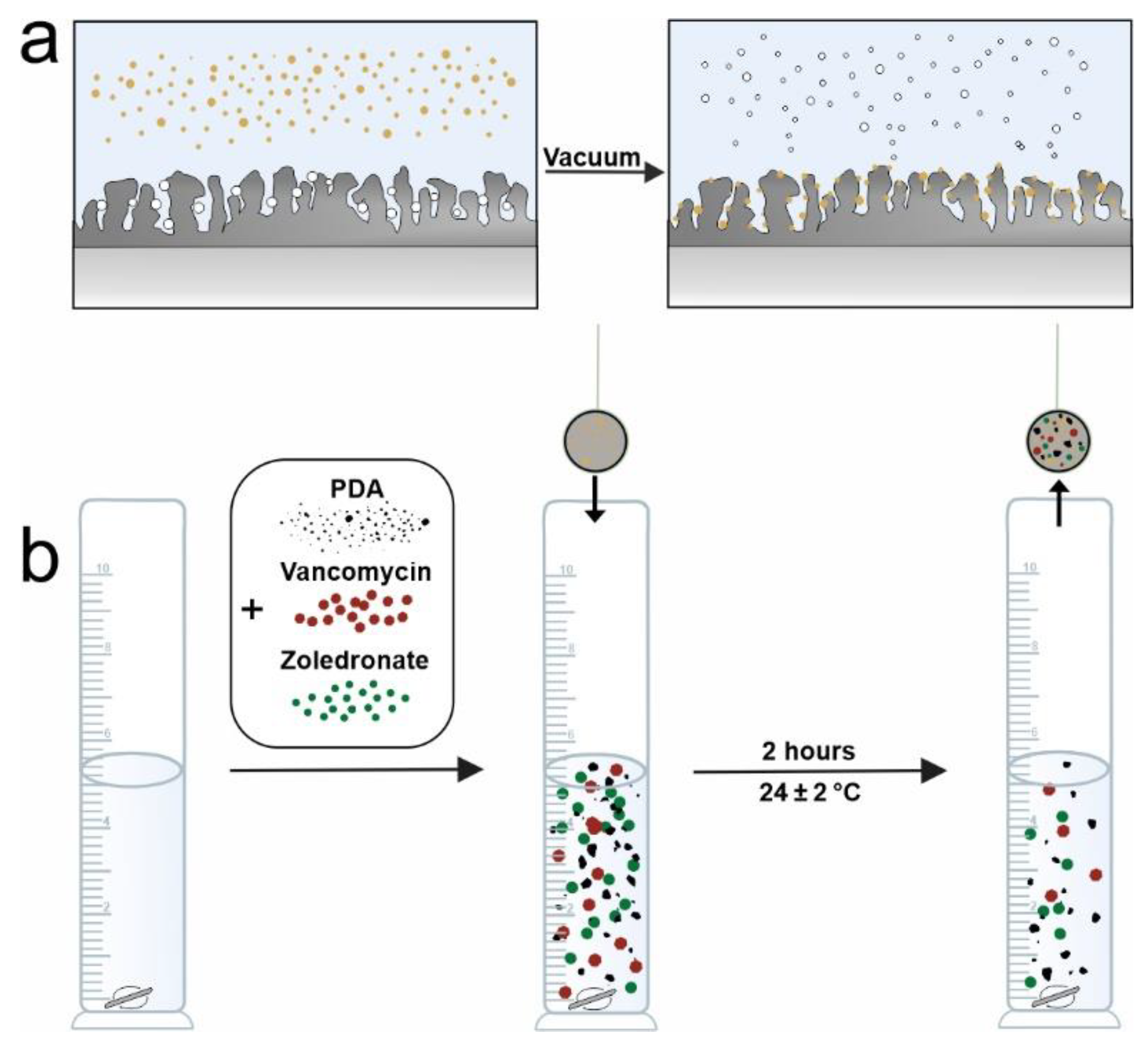
Figure 2.
Dilatometric curves: overall shrinkage of the samples (a); shrinkage for samples containing different amount of CaCO3 (b); time-dependent shrinkage rate for samples containing different amount of CaCO3 (c); temperature-dependent shrinkage rate for samples containing different amount of CaCO3 (d).
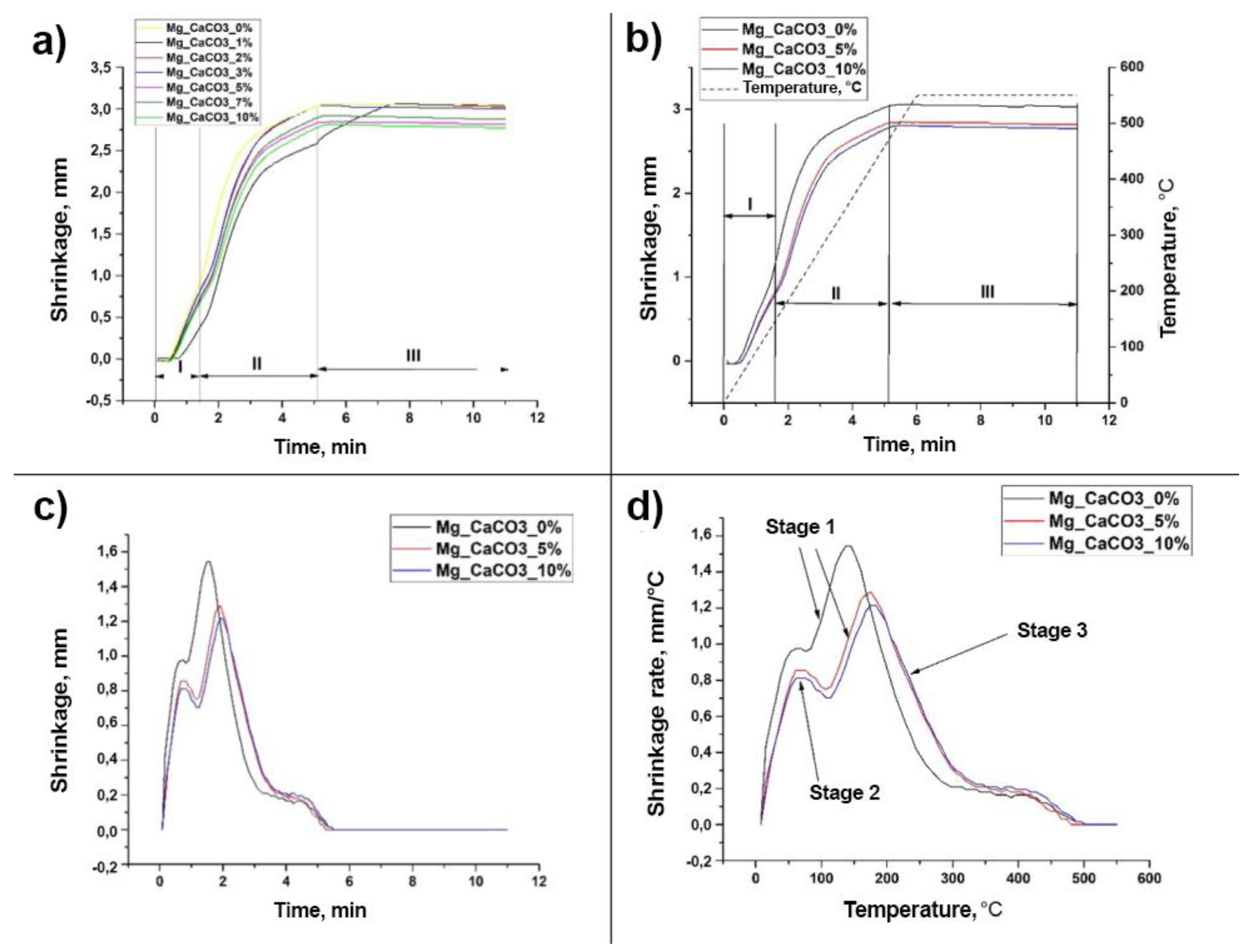
Figure 3.
Optical images of SPS samples with different amounts of calcium carbonate in the coating after carbonic acid etching: a – 0 wt.%, b – 1 wt.%, c – 2 wt.%, d – 3 wt.%, e – 5 wt.%, f – 7 wt.%, g – 10 wt.%; as well as PEO coatings obtained on these samples: a’ – 0 wt.%, b’ – 1 wt.%, c’ – 2 wt.%, d’ – 3 wt.%, e’ – 5 wt.%, f’ – 7 wt.%, g’ – 10 wt.%. Sample with hybrid layer: f” – 7 wt.%.
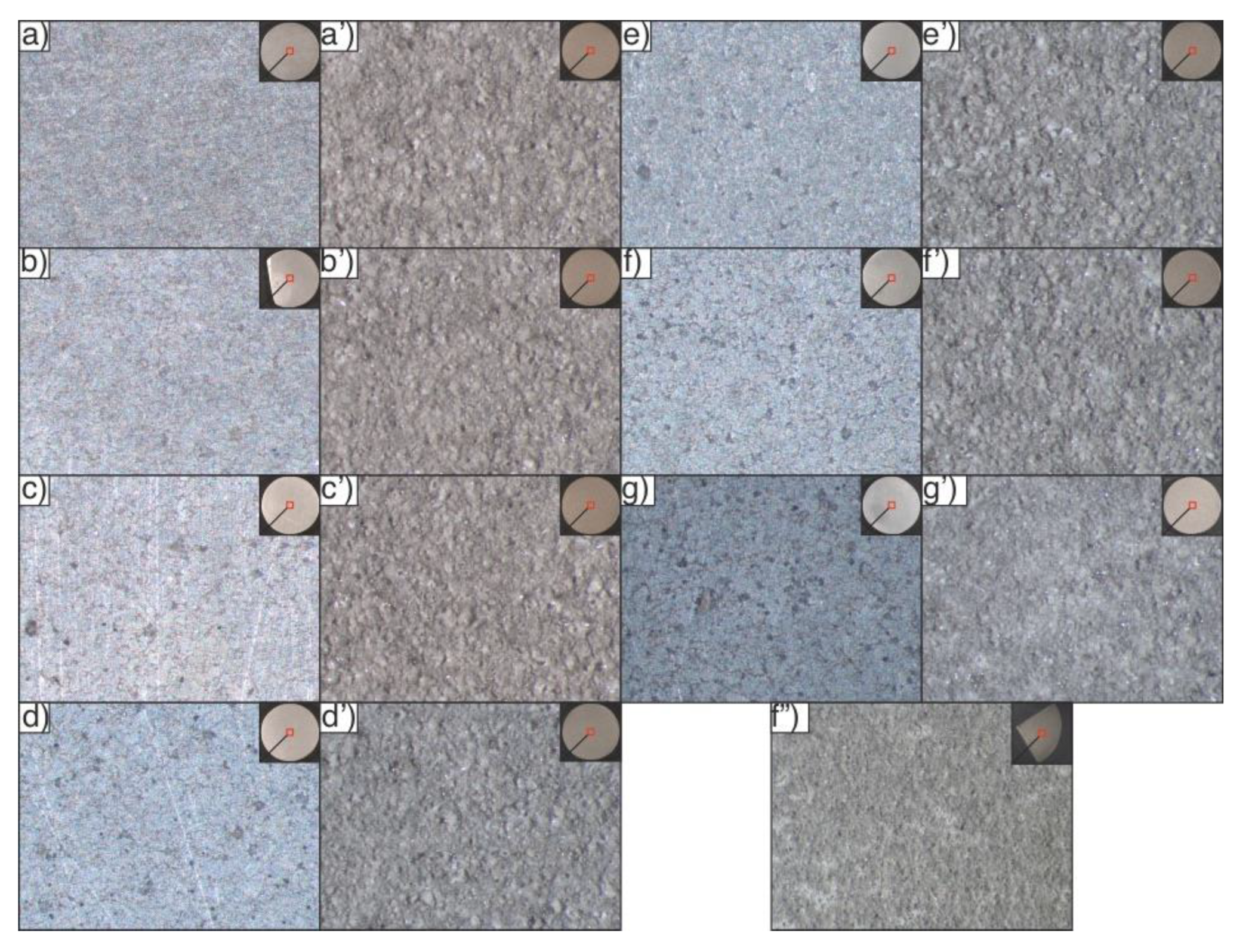
Figure 4.
SEM images of the surface of bare SPS samples, with PEO and with hybrid coating.
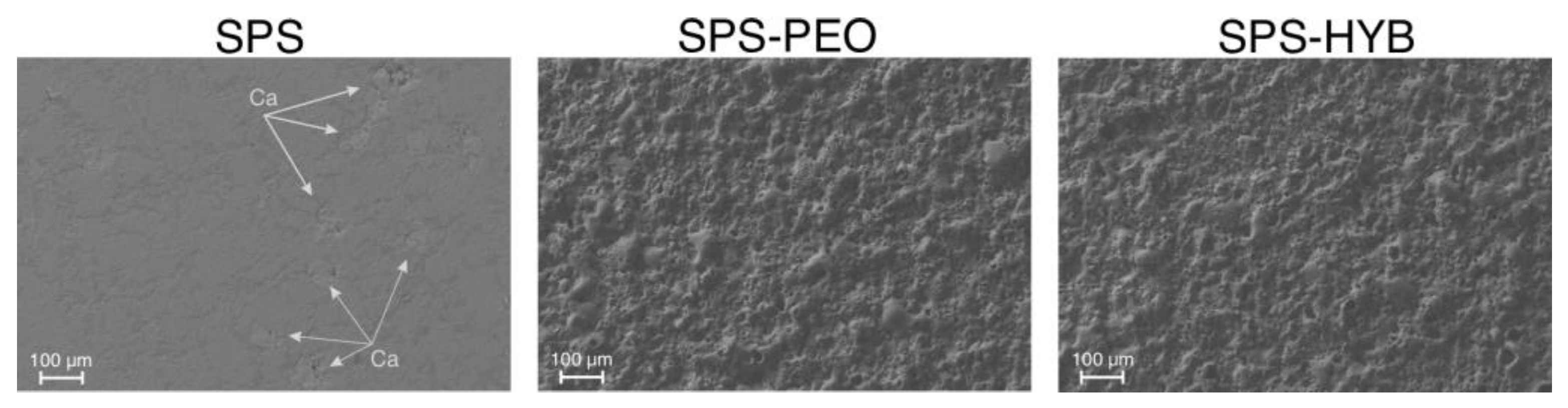
Figure 6.
The shape of the water drops on different samples and CAs value.
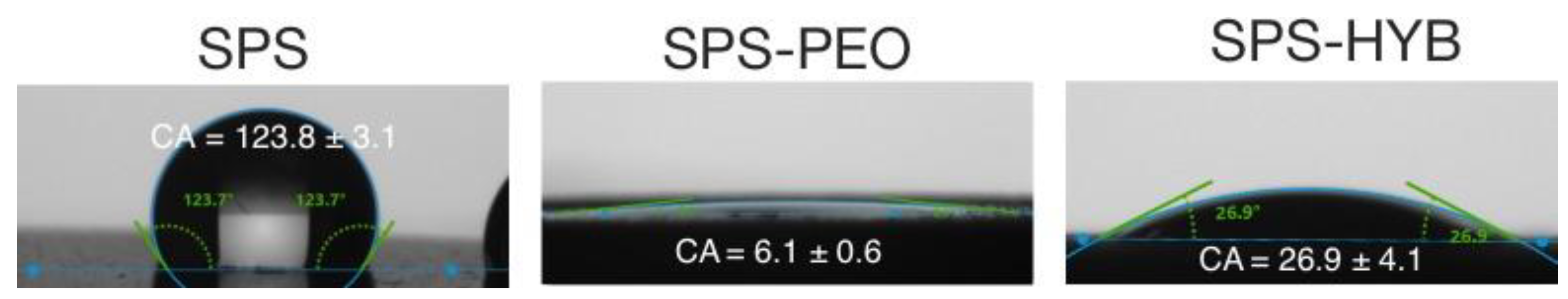
Figure 7.
The samples’ surface free energy.
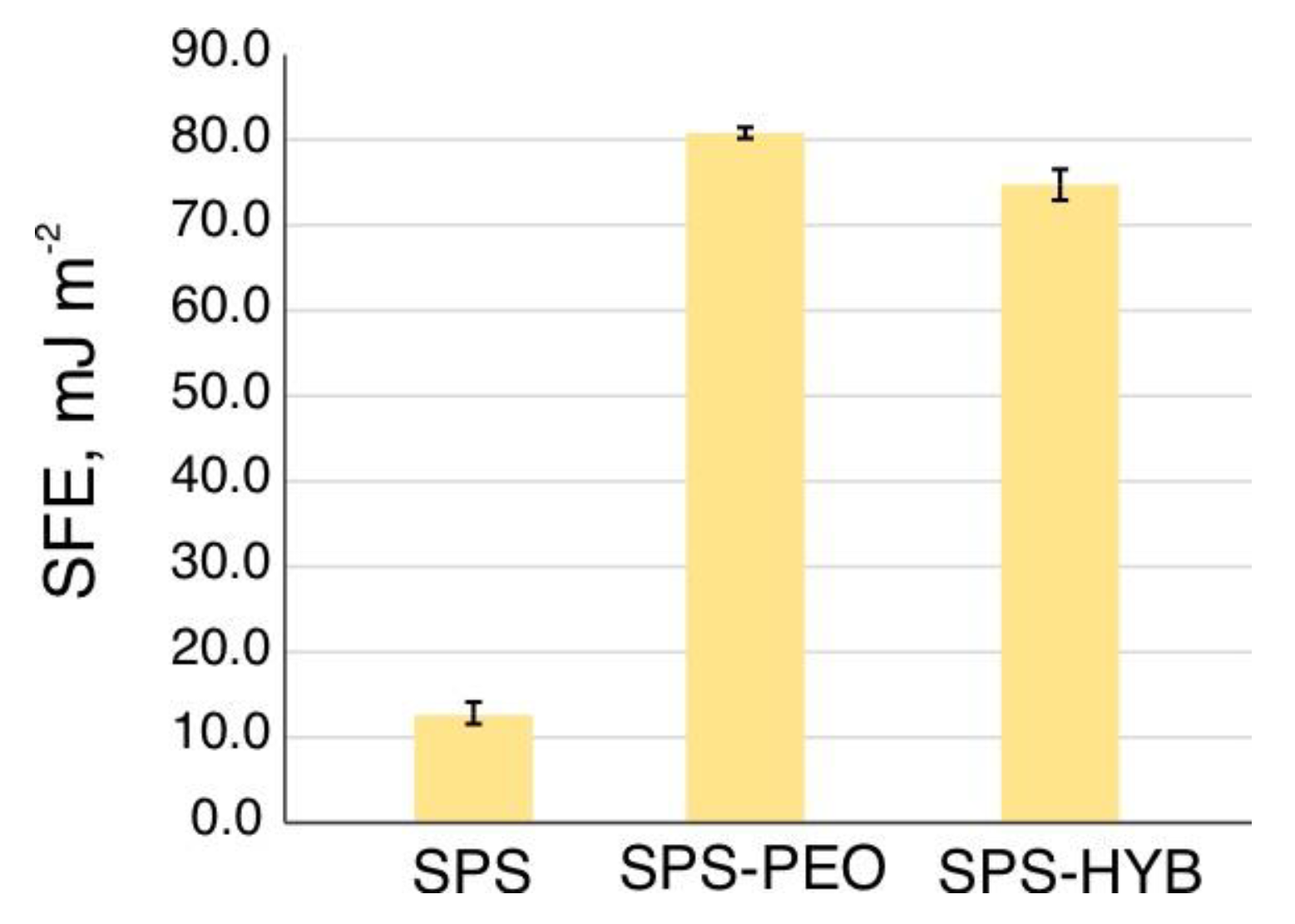
Figure 8.
Image of SBF drops on samples with different types of surface treatment.
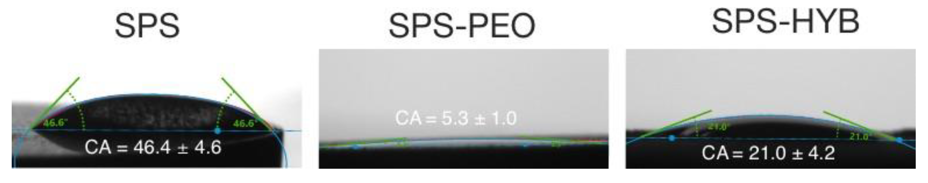

Table 1.
Description of the samples studied and corresponding designation. SPS is a spark plasma sintering, PEO is a plasma electrolytic oxidation, PDA is a polydopamine, HYB is hybrid.
Table 1.
Description of the samples studied and corresponding designation. SPS is a spark plasma sintering, PEO is a plasma electrolytic oxidation, PDA is a polydopamine, HYB is hybrid.
| Sample | Designation |
|---|---|
| Bare SPS-produced sample PEO coating |
SPS SPS-PEO SPS-HYB |
| PEO coating with vancomycin, menaquinone-7, zoledronate, PDA |
Table 2.
Description of the samples studied and corresponding designation. SPS is a spark plasma sintering.
Table 2.
Description of the samples studied and corresponding designation. SPS is a spark plasma sintering.
| Element | Designation |
|---|---|
| P Ca Mg Na |
29.4 28.5 21.1 12.6 5.9 2.5 |
| Si Other |
Table 3.
Roughness parameters (arithmetical mean height Sa and root mean square height Sq) of samples with different mass fractions of calcium carbonate.
Table 3.
Roughness parameters (arithmetical mean height Sa and root mean square height Sq) of samples with different mass fractions of calcium carbonate.
| Parameter | CaCO3 content in SPS-sample, wt.% | ||||||
| 0 | 1 | 2 | 3 | 5 | 7 | 10 | |
| Sa (µm) | 4.8±0.4 | 5.2±0.1 | 5.5±0.8 | 5.3±0.1 | 6.4±0.5 | 6.4±0.6 | 5.9±0.3 |
| Sq (µm) | 6.3±0.6 | 6.9±0.4 | 7.1±1.0 | 6.8±0.1 | 8.2±0.7 | 8.3±0.9 | 7.6±0.3 |
Table 4.
Values of contact angles and free surface energy for SPS samples.
| Sample | θ, ° | γsd, mJ/m2 | γsp, mJ/m2 | γs, mJ/m2 |
| H2O | ||||
| SPS | 123.8±3.08 | 12.85±1.63 | 0.04±0.01 | 12.86±1.67 |
| SPS-PEO | 6.1±0.6 | 50.19±0.12 | 30.62±0.09 | 80.81±0.22 |
| SPS-HYB | 26.9±4.1 | 49.22±0.60 | 25.57±1.68 | 74.79±4.39 |
Table 5.
Wear of the coatings.
| Sample | Wear (mm/(N m) |
|---|---|
| SPS | (4.7±2.3) · 10-3 |
| SPS-PEO | (4.6±1.0) · 10-2 |
Disclaimer/Publisher’s Note: The statements, opinions and data contained in all publications are solely those of the individual author(s) and contributor(s) and not of MDPI and/or the editor(s). MDPI and/or the editor(s) disclaim responsibility for any injury to people or property resulting from any ideas, methods, instructions or products referred to in the content. |
© 2025 by the authors. Licensee MDPI, Basel, Switzerland. This article is an open access article distributed under the terms and conditions of the Creative Commons Attribution (CC BY) license (http://creativecommons.org/licenses/by/4.0/).
Copyright: This open access article is published under a Creative Commons CC BY 4.0 license, which permit the free download, distribution, and reuse, provided that the author and preprint are cited in any reuse.


