
Submitted:
21 July 2025
Posted:
22 July 2025
You are already at the latest version
Abstract
The detection of faint, fast-moving objects such as space debris, in optical data is a major challenge due to their low signal-to-background ratio and short visibility time. This work addresses this issue by implementing the Stack-CNN algorithm, originally designed for offline analysis, on an FPGA-based platform to enable real-time triggering capabilities in constrained space hardware environments. The Stack-CNN combines a stacking method to enhance the signal-to-noise ratio of moving objects across multiple frames with a lightweight convolutional neural network optimized for embedded inference. The FPGA implementation was developed using a Xilinx Zynq Ultrascale+ platform and achieves low-latency, power-efficient inference compatible with CubeSat systems. Performance was evaluated using both a physics-based simulation framework and data acquired during outdoor experimental campaigns. The trigger maintains high detection efficiency for 10 cm-class targets up to 30-40 km distance and reliably detects real satellite tracks with signal levels as low as 1% above background. These results validate the feasibility of on-board real-time debris detection using embedded AI, and demonstrate the robustness of the algorithm under realistic operational conditions. The study was conducted in the context of a broader technology demonstration project, called DISCARD, aimed at increasing space situational awareness capabilities on small platforms.
Keywords:
space debris
; FPGA implementation
; convolutional neural networks
; DISCARD
; real-time processing
; embedded AI
; stacking algorithm
; Stack-CNN
; CubeSat
1. Introduction
The proliferation of space debris, especially in low Earth orbit (LEO), poses a growing threat to operational satellites and space missions. While large debris fragments are routinely tracked by ground-based surveillance networks operated by agencies such as ESA and NASA [1,2], smaller objects in the 1–10 cm size range remain undetectable by conventional systems. These objects are too small to be catalogued yet large enough to cause catastrophic damage in the event of a collision. Developing onboard detection systems capable of recognizing such debris in real-time is a critical step toward improving space situational awareness.
Machine learning techniques, and in particular convolutional neural networks (CNNs), have recently shown great potential in detecting faint signals hidden by the noise in astrophysical and orbital observation contexts [3,4]. However, deploying such models onboard small satellites or CubeSats introduces hardware constraints that limit the use of traditional deep learning architectures. For this reason the combination of a lightweight CNN with a stacking procedure known as the Stack-CNN algorithm offers a promising solution for real-time detection of faint, fast-moving objects in noisy optical data [5].
The stacking method, originally proposed by Yanagisawa for GEO debris detection [6], enhances the signal-to-background ratio (SBR) by coherently integrating frames along hypothetical motion vectors. This technique was later adapted as a second-level trigger in the JEM-EUSO program [7]. The CNN component, optimized for low parameter count and shallow architecture, enables efficient classification of stacked frames while remaining compatible with field-programmable gate array (FPGA) implementation [8].
In this work, it is presented the FPGA implementation of the Stack-CNN algorithm using a Zynq Ultrascale+ platform. Its performance is evaluated through extensive simulations and experimental campaigns. The capability to detect objects with low SBR is evaluated using both synthetic and real-world data, including satellite passages observed during outdoor campaigns. The implementation demonstrates real-time processing capability, robustness to background noise, and high detection efficiency, confirming its suitability for embedded systems with constrained resources.
2. Materials and Methods
2.1. Overview of the Stack-CNN Algorithm
The Stack-CNN algorithm is designed to detect faint, fast-moving objects in optical image sequences, with a particular focus on space debris and meteors. It combines two core stages: a stacking operation that enhances the visibility of linear motion signals across frames, and a convolutional neural network (CNN) that performs binary classification on the resulting stacked images. This hybrid approach allows for effective detection even in low signal-to-noise conditions, while maintaining a computational footprint compatible with embedded hardware platforms. The following subsections describe the two main components of the algorithm: the Stacking Method and the CNN-based classification.
2.1.1. Stacking Method
The Stacking Method is applied to objects, such as space debris or meteors, that move linearly across the field of view (FoV) of an optical instrument, with fixed apparent velocity and direction . These motion parameters are typically a function of the satellite’s orbit and pointing direction. The method is built upon two core operations: shifting and summation [5,9].
Given a sequence of n frames, each defined as with and pixel coordinates , the shifting process is designed to align the signal of a moving object across time. This is done by reversing the object’s expected motion, effectively “freezing” its position in the stack. The shifting vector is derived from the object’s velocity and direction and is defined as:
Since the image grid is discrete, and are rounded to the nearest integer via the operation. This yields a shifted image as:
After shifting all n frames according to the hypothesized trajectory, they are summed to obtain the stacked image:
This operation coherently integrates signal contributions from a moving object while background noise, assumed to be temporally uncorrelated, tends to average out. The improvement is quantified through the signal-to-noise ratio (SNR), defined as:
Here, is the average background level, and its standard deviation. Assuming a Poissonian noise model, . In this work, a nominal background of 1 photon/GTU (Gate Time Unit) is considered, aligned with the Mini-EUSO calibration [10,11].
For stacked images, the signal contribution grows linearly with the number of frames n, while the noise grows as , resulting in an overall enhancement:
It is critical to choose n such that it matches the effective duration of the object’s visibility within the frame sequence. A mismatch could lead to a reduced improvement in SNR. In our experimental context, typical values of n range from 6 (e.g., for short-lived meteor events, fast debris) up to 40 (e.g., for slower, longer debris crossings). More details can be found in "Stack-CNN algorithm: A new approach for the detection of space objects" by Montanaro et al. [5]
2.1.2. Quantized CNN Architecture
The convolutional neural network used in the Stack-CNN pipeline performs binary classification on stacked images to determine whether a valid object track is present. While the original model proposed by Montanaro et al. [5] was designed for offline analysis with relatively high-resolution input, the version proposed here is optimized for real-time inference on resource-constrained FPGA hardware. The two architectures share a similar logic and structure, but differ in image resolution, layer sizes, and quantization.
The original Stack-CNN model, was designed to process stacked images of size pixels. It consists of three convolutional layers with ReLU activations and kernels, followed by max-pooling layers to reduce spatial dimensions. After feature extraction, the output is flattened and passed through three fully connected layers, with the final layer using a sigmoid activation to yield a binary classification output. The network contains approximately 16,825 trainable parameters and was trained using binary cross-entropy loss with the Adadelta optimizer [12]. The shallow depth and relatively low parameter count make it suitable for deployment in embedded systems.
To meet the requirements of real-time, low-power deployment on FPGA hardware, a compact convolutional neural network using the Brevitas quantization-aware training framework [13] was designed. The architecture is specifically tailored to process input images of size pixels, matching the resolution of the sensor used in the test system. All weights, activations, and biases are quantized to 8-bit fixed-point integers, ensuring full compatibility with hardware accelerators and enabling highly efficient inference on the Xilinx Zynq Ultrascale+ FPGA platform.
The network structure, depicted in Figure 1, consists of two convolutional blocks, each comprising a convolutional layer with ReLU activation and max-pooling, followed by a flattening operation and two fully connected layers. The final layer applies a sigmoid activation function for binary classification.
A detailed breakdown of the number of parameters in each layer is provided in Table 1, confirming the suitability of the network for low-resource embedded systems. In total, the model comprises 37697 parameters, allowing for fast and lightweight inference.
Figure 1.
Schematic representation of the quantized CNN architecture implemented on FPGA. The model processes stacked images and consists of two convolutional blocks (Conv + ReLU + MaxPool), followed by a flattening layer and two fully connected layers. A final sigmoid activation performs binary classification. This illustration was generated using the NN-SVG API [14].
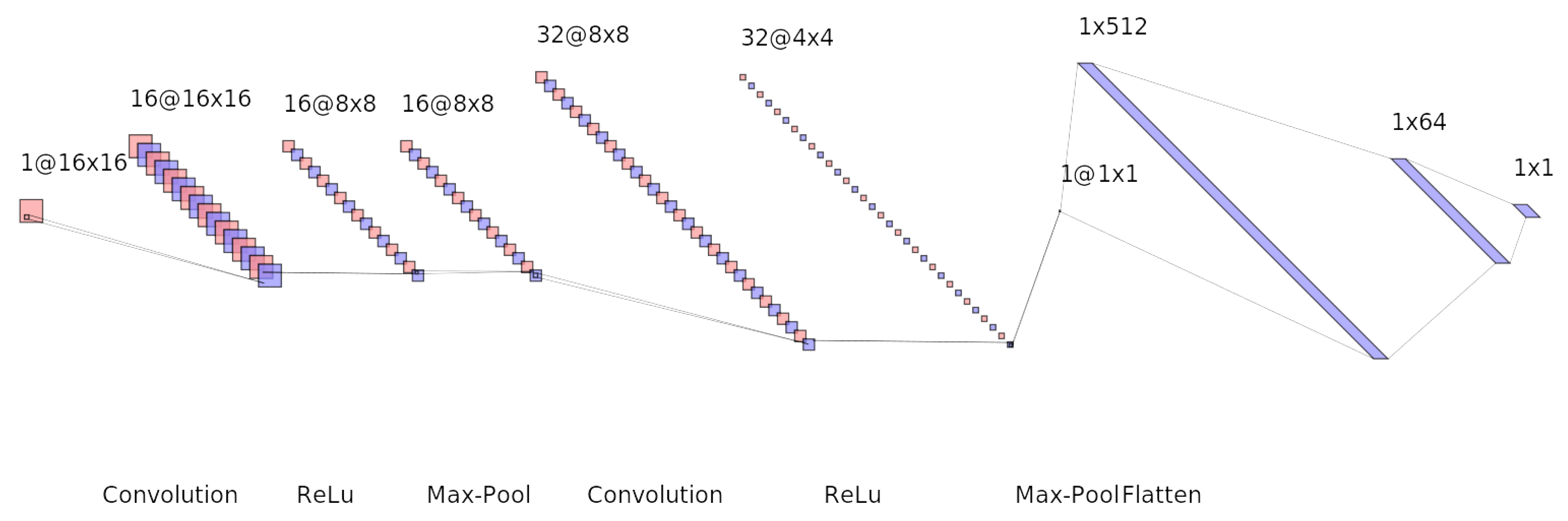

Table 1.
Parameter count for each layer in the quantized CNN architecture.
| Layer | Output Shape | Parameters |
|---|---|---|
| Conv2D (1→16) | 160 | |
| Conv2D (16→32) | ||
| FC (Flatten 512 → 64) | 64 | |
| FC (64 → 1) | 1 | 65 |
| Total | — | 37,697 |
This structure totals 512 input features to the first fully connected layer (since 32 channels × spatial size). All layers use 8-bit quantized weights and activations, and biases are quantized using the Int8Bias strategy. The model is exported to ONNX format [15] and compiled for hardware deployment using the Vitis AI toolchain [16], which integrates quantized inference engines with FPGA-accelerated pipelines.
While the total number of parameters in our quantized CNN architecture exceeds that of the original Stack-CNN presented in [5], this increase is the result of deliberate architectural choices tailored for efficient FPGA deployment. Our model was designed and trained using quantization-aware training (QAT) via the Brevitas framework [13], ensuring that all weights, activations, and biases are represented as 8-bit fixed-point integers. This format is ideal for low-power inference on FPGA devices, as it minimizes memory bandwidth and computation overhead compared to floating-point implementations.
The original Stack-CNN model, although smaller in total parameter count, includes multiple dense layers and was trained using standard 32-bit precision. Its design does not incorporate quantization, which limits its direct applicability to resource-constrained environments such as embedded FPGAs, where floating-point arithmetic can significantly degrade throughput and increase power consumption.
In contrast, our architecture emphasizes structural regularity, with consistent convolutional blocks and minimal fully connected layers. This organization allows for better pipelining and parallelization on the FPGA fabric. Furthermore, by using smaller input dimensions () and keeping kernel sizes uniform (), our model facilitates efficient reuse of computation blocks and memory. Despite the presence of a relatively large fully connected layer (512→64), the quantized representation ensures that its resource impact remains acceptable. Empirical evaluations confirmed that our model not only meets real-time inference requirements but also achieves superior classification accuracy over the original Stack-CNN, particularly in high-noise and low-SNR conditions.
This demonstrates that, when properly quantized and structured, even moderately larger networks can outperform smaller ones in hardware efficiency and detection capability, as shown in Table 2.
The result is a compact, efficient network that maintains competitive detection performance while staying within the strict resource and latency constraints required by spaceborne CubeSat applications.
2.2. FPGA Implementation
The deployment of the quantized CNN model on the Xilinx Ultrascale+ ZCU104 FPGA board was carried out through a streamlined workflow built entirely within the Vitis AI framework. This section provides an overview of the design flow, toolchain components, and the quantization strategy adopted to optimize the model for efficient inference on low-power hardware.
2.2.1. Design Flow and Toolchain
The complete FPGA implementation of the Stack-CNN model was developed using the Vitis AI framework [16], which provides a comprehensive toolchain for deploying deep learning models on Xilinx devices. The process begins with training the quantized CNN in PyTorch using the Brevitas library [13], which supports quantization-aware training (QAT) and fixed-point simulation.
Once training is complete, the model is exported to the ONNX format [15] and then passed through the Vitis AI Quantizer and Compiler. The quantizer finalizes the 8-bit fixed-point representation, ensuring compatibility with the Deep Processing Unit (DPU) available on the Zynq Ultrascale+ platform. The compiler maps the network to the target DPU configuration and generates an optimized model for inference.
The bitstream and AI artifacts are then integrated into the overall firmware project using PetaLinux tools and deployed to the ZCU104 evaluation board. Runtime inference is executed via the Vitis AI Runtime API (VART), enabling tight coupling between software and FPGA hardware acceleration.
2.2.2. Model Optimization and Quantization
To ensure optimal performance on embedded hardware, the model was trained using quantization-aware training (QAT), which simulates reduced precision during both forward and backward passes. This was accomplished using Brevitas, which provides drop-in quantized modules for PyTorch while preserving compatibility with the Xilinx Vitis AI stack.
All weights, activations, and biases were quantized to 8-bit integers, significantly reducing memory usage and allowing efficient mapping to FPGA resources such as LUTs, DSP slices, and BRAMs. Notably, the quantization-aware training approach preserves model accuracy, avoiding the degradation typically observed in post-training quantization workflows.
The quantized model was exported in ONNX format and processed by the Vitis AI Quantizer to apply further optimizations. These include weight folding, batch normalization absorption, and removal of unused graph operations. The resulting model was compiled into a hardware-friendly format suitable for deployment on the ZCU104’s DPU core, ensuring real-time inference with minimal latency and power consumption. The structural and export details of the quantized Stack-CNN are summarized in Table 3.
2.3. Simulation Framework for evaluating Detection Efficency of the Quantized Stack-CNN Algorithm
To support the development and evaluation of the implemented Stack-CNN architecture for space debris (SD) detection, we developed a dedicated simulation framework designed to reproduce realistic observation scenarios under controlled conditions. The framework generates synthetic datasets that emulate the optical detection of small orbital debris fragments as they traverse a pixel sensor, matching the resolution of the deployed hardware platform.
Each simulated sequence consists of 128 frames, each lasting 50 ms, with fixed spatial resolution ( pixels). The background signal is modeled as a strong Poissonian noise source centered around 20000 photons per pixel per frame, reflecting typical conditions encountered on space-based or high-altitude platforms. A single moving object, representing a debris fragment, is injected into each sequence with randomized direction, speed, and intensity. The object’s trajectory, size, and brightness are parameterized based on its physical dimensions (1–20 cm in diameter) and distance from the observer (10–100 km). Motion starts randomly between frame 6 and frame 20, entering from one of the four edges, and proceeds with velocities that match the 3D positioning of the object in the simulated field of view of the detector.
To simulate realistic optical signatures, we modeled the interaction between solar UV radiation and the surface of the debris. A typical fragment with a radius of 0.1 m and an albedo of 0.1, when illuminated by solar photons in the 300–400 nm band, receives an incident flux of approximately . Assuming Lambertian reflection over a hemisphere, the reflected flux becomes approximately . Only a fraction of these photons reach the detector, depending on the focal surface area, the distance to the object, and the phase angle between the incident sunlight and the observer. The latter can be properly chosen, according to the orbital configuration, in order to enhance the amount of reflected light reaching the focal plane. The resulting photon flux at the sensor (PhFS) scales with the ratio , linking the physical parameters of the system to the signal level observed on the focal surface.
The spatial distribution of the signal on the sensor is shaped using a custom point spread function (PSF) that mimics the blurring effects of optical systems. Approximately 40% of the signal energy is assigned to the central pixel, while the remainder is distributed to neighboring pixels according to a physically inspired kernel. This configuration allows the simulation to account for realistic signal shapes and sub-pixel movements. Figure 2 shows an example of frames generated by this simulation framework. In total, the simulation campaign spans 15 discrete object sizes, 10 different distances, and 10 unique velocity profiles per distance, with 100 randomized realizations for each configuration. This results in a comprehensive dataset suitable for training, validating, and benchmarking detection algorithms, particularly under low signal-to-noise ratio and transient conditions that challenge traditional techniques.
2.4. Prototype Detector Description
This section outlines the experimental setup employed to validate the Stack-CNN algorithm, with a focus on the structure and functionality of the detector prototype. The design and components are derived from the JEM-EUSO collaboration and include a Photon Detection Module (PDM) based on an Elementary Cell (EC) unit. The detection system consists of a 16×16 pixel photomultiplier array coupled with a Fresnel lens, forming the core of the optical assembly. Each part are integrated inside a maechanical structure performed in collaboration with INFN Turin (Figure 3)
This iteration of the prototype detector shown in Figure 3 is composed of:
- a)
- Front section: This contains the optical system, which includes a 25 cm diameter Fresnel lens.
- b)
- Back section: This part has all the connector to comunicate with the electronics inside.
- c)
- Inner section: This is the most relevant part and it houses the EC with four photomultiplier tubes arranged in a 16×16 pixel matrix. Located behind the photomultipliers are four custom ASICs developed by the JEM-EUSO program [17], which are responsible for converting the analog signals from the photomultipliers into digital signals. Behind the PDM there are the electronic components of the data acquisition system, including two Zynq boards (Xilinx Zynq-7000 and Xilinx Artix-7), as well as the high-voltage power supply board that provides the necessary voltage for the photomultiplier operation.
2.4.1. Observation Conditions and Data Collection
To validate the overall acquisition system and evaluate the performance of the Stack-CNN algorithm, several outdoor observation campaigns were conducted. These campaigns were carried out during sunset to optimize conditions for detecting satellite trajectories, taking advantage of the low background light and the period during which satellites are still illuminated by the Sun. A 10 Micron LX2000 telescopic mount was used to ensure precise alignment with known satellite trajectories, thereby enabling accurate calibration of the detector system. This configuration facilitated the reliable association of detected signals with known orbital objects. The primary objective of these campaigns was to identify the specific satellites under observation, enabling the determination of their physical dimensions and apparent magnitudes, which are crucial for assessing the detection capabilities of the system under realistic observational conditions.
Figure 4 shows an example of three frames acquired during one of these campaigns, where the trajectory of a satellite is visible crossing the sensor’s field of view.
3. Results
In this section the main results from the discussed work are reported.
3.1. Algorithm Profiling Results
A critical aspect of validating the implemented Stack-CNN algorithm was the assessment of its execution performance under realistic data streams. This profiling analysis aimed to confirm that the model could reliably operate within the real-time constraints required for onboard triggering and acquisition. The following results illustrate the temporal behavior of the processing pipeline across different input conditions.
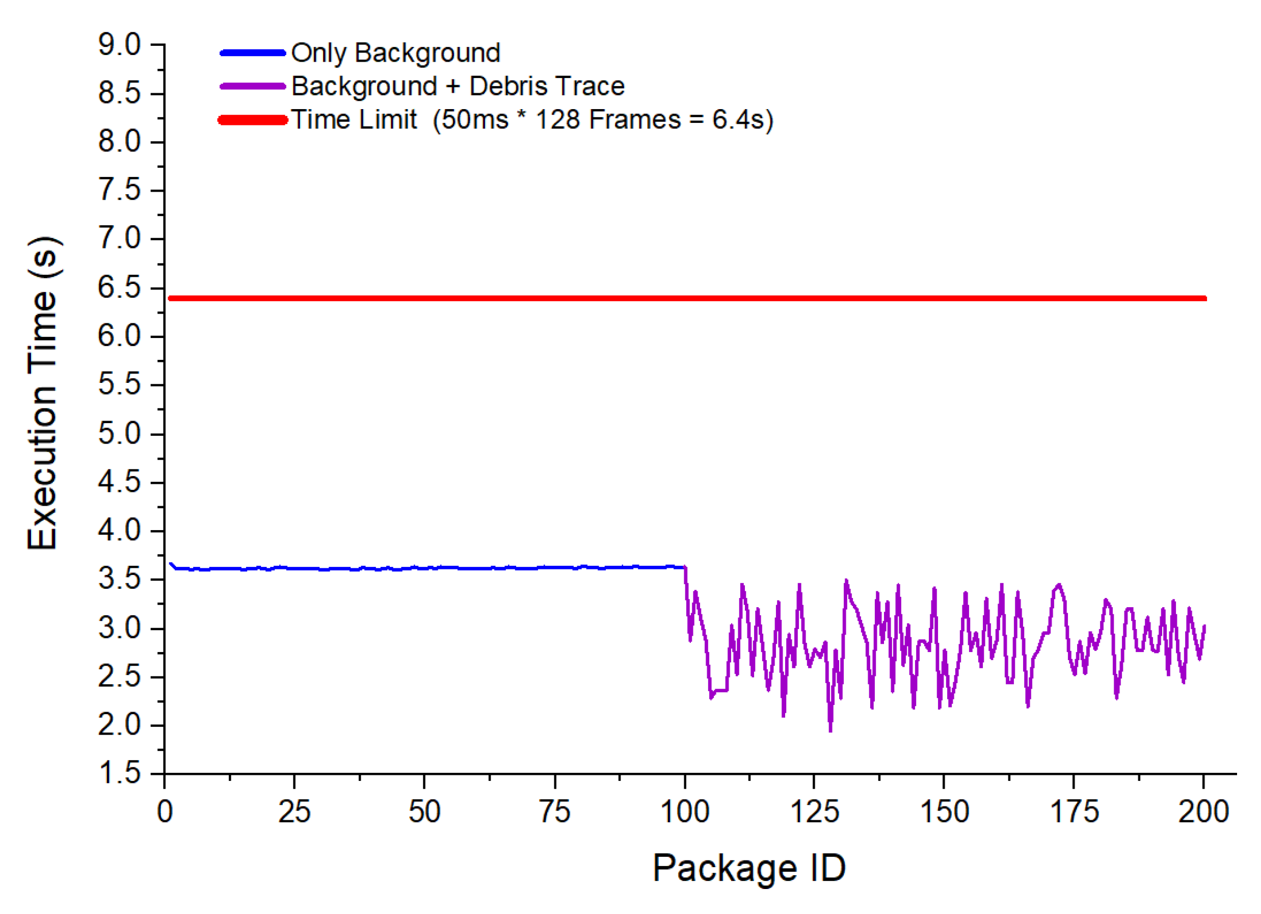
Figure 5 reports one of the profiling studies conducted during this validation phase. In this experiment, two configurations were evaluated: processing sequences containing only background noise (blue curve) and sequences containing both background and simulated debris traces (purple curve). For each package of input frames, the total execution time was measured and plotted as a function of the package ID.
The results show that the inference time remained stable and well below the imposed processing time limit of 6.4 seconds per package (indicated by the red line), which corresponds to processing 128 frames at 50 ms per frame. When only background data was present, the execution time fluctuated around 4 seconds per package, reflecting the baseline computational load of the stacking and CNN processing stages. When debris traces were included, execution time exhibited a slight decrease and higher variability, with values typically between 2.5 and 3.5 seconds. This variability is attributed to the dynamic activation patterns in the CNN layers when debris-like features were detected.
Overall, the profiling confirmed that the implemented pipeline met the real-time constraints required for onboard operation, leaving sufficient margin for additional pre-processing or communication overhead if necessary.
Figure 5.
Profiling study of the Stack-CNN algorithm implemented in FPGA. The blue curve shows execution time when processing background-only sequences, while the purple curve corresponds to sequences containing debris traces. The red line indicates the maximum allowable processing time per data package.
3.2. Stack-CNN Performances, Simulation Framework
Preliminary results on detection efficiency for 10 cm diameter debris are shown in Figure 6. In this test, the Stack-CNN algorithm was executed directly on the FPGA, using the quantized model deployed on the DPU of the ZCU104 board. Simulated input sequences were streamed to the board via a custom SSH-based interface, designed to emulate real-time telemetry from an onboard optical sensor.
The figure reports the trigger efficiency as a function of binned distance intervals from 0 to 100 km. The Stack-CNN trigger achieves 80% efficiency in the 0–10 km bin, with a gradual decline to 65% and 62% in the 10–20 km and 20–30 km bins, respectively. The efficiency drops to 49% between 30–40 km, and further to 29% between 40–50 km. Beyond this range, performance sharply degrades, with negligible detection above 50 km. These results highlight the distance-dependent sensitivity of the algorithm, driven by the decreasing signal-to-background ratio and the limitations imposed by the current optics and background levels.
This binned analysis provides a consolidated overview of the trigger’s operating range, guiding further optimization of the algorithm and its training procedures to enhance detection capability at extended distances.
3.3. Stack-CNN Performances and Experimental Campaigns
To assess the performance of the implemented Stack-CNN algorithm under realistic observational conditions, experimental campaigns were conducted using the prototype detector. A dataset comprising seventeen satellite passages recorded during twilight was assembled, a condition that offers favorable contrast between reflected sunlight and the diffuse sky background.
Figure 7 shows the measured signal over background (SOB) for each event. The percentage SOB varied between 1.0% and 8.8%, with a mean of approximately 4.0%. A horizontal red line indicates this value, while a blue line marks the effective experimental detection threshold, set at 1.5%. Notably, several passages exceed 4% over background, confirming the capability of the Stack-CNN trigger to confidently detect faint moving sources under realistic conditions.
The variability observed across events is attributable to differences in apparent magnitude, distance, and the reflective properties of the satellites. Events below the 1.5% threshold represent the lowest detectable contrast achievable with the current optical configuration and background suppression. To identify the observed satellites, acquisition times and pointing coordinates were cross-referenced with orbital data from the Heavens-Above satellite tracking service [18]. This process allowed the trajectories of most targets to be matched with a high degree of confidence, while in some cases, minor discrepancies between predicted and observed positions introduced residual uncertainty. One of the brighter passages was tentatively attributed to Starlink-5172, based on close agreement in timing and motion patterns, although an exact identification could not be fully confirmed. Overall, the satellites in this group exhibited similar apparent trajectories and brightness profiles, supporting the hypothesis that they belonged to the Starlink constellation, whose units share nearly identical physical dimensions and reflective characteristics [19].
For this candidate passage, the reference target has nominal dimensions of approximately m and a deployed solar array length near 8 m, resulting in an effective reflective area of about 8 m2. While uncertainties remain regarding the precise orientation and illumination geometry relative to the observer, the signal intensity was averaged over the entire passage to mitigate these effects. Based on this measurement, the experimental detection limit of the system was estimated to be approximately equivalent to an object of 0.35 m diameter observed at 100 km, providing a practical, though approximate, benchmark for the minimum detectable debris size under comparable conditions.
These results validate the feasibility of operating the Stack-CNN algorithm in real-time onboard scenarios, offering robust detection performance for targets with low contrast over the background. Ongoing analysis of additional satellite passes, including fainter or less well-characterized objects, will further refine the estimation of the system’s detection limits and improve the characterization of sensitivity under varying observation conditions.
4. Discussion
The results presented in this work demonstrate that the Stack-CNN algorithm, when deployed on an FPGA-based hardware platform, meets the real-time processing requirements essential for onboard detection of small orbital debris. The profiling results confirmed that the inference pipeline maintained stable execution times well below the operational limit of 6.4 seconds per data package, even when processing sequences containing debris-like traces. This finding supports the initial working hypothesis that a quantized CNN, optimized for resource-constrained devices, could be integrated into an autonomous trigger system without exceeding the temporal constraints typically encountered in space-based observation platforms.
The detection efficiency analysis, based on synthetic datasets generated with a physics-based simulation framework, revealed that the Stack-CNN algorithm maintains high detection rates for 10 cm debris up to approximately 30 km, with efficiencies exceeding 60%. A progressive decline is observed beyond this range, with efficiency dropping below 50% between 30–40 km and falling to 29% in the 40–50 km bin. Detection capability becomes negligible above 50 km. This behavior reflects the expected decrease in signal-to-background ratio with increasing distance, consistent with observation geometry and the optical limitations of the system. These results align with prior findings from space-based missions such as Mini-EUSO [10], which emphasized the importance of photon statistics and contrast levels when detecting faint objects against diffuse background illumination.
Importantly, the results of the experimental campaigns conducted under real observational conditions consolidate these simulation-based findings. The measured signal over background values for a set of seventeen satellite passages showed a range of 1–9%, with a mean value around 4%, consistent with the modeled sensitivity thresholds. While precise identification of all targets was limited by orbital data uncertainties, the analysis of trajectories and brightness profiles suggested that most of the observed objects belonged to the Starlink constellation [19], whose known dimensions provided a reference for estimating detection limits. In particular, the passage tentatively attributed to Starlink-5172 allowed extrapolation to an equivalent minimum detectable diameter of approximately 0.35 m at 100 km under low-background conditions. This real-world benchmark validates the capability of the system to detect faint moving objects in operational scenarios and highlights the relevance of carefully characterizing observation geometries and illumination.
From a technical perspective, the use of FPGA acceleration to execute quantized convolutional neural networks in real time builds on recent advances in edge computing for space applications [20,21]. This approach demonstrates that even within the strict power and resource constraints typical of small satellite platforms, it is possible to implement sophisticated detection algorithms capable of operating autonomously without ground intervention.
Nevertheless, some limitations were identified. The sensitivity threshold observed in the 40–50 km range, as well as the variability in measured signal levels across different passes, suggests that further improvements in model training, quantization strategies, and pre-processing techniques will be necessary to extend the detection envelope. In particular, refining the simulation framework to include more complex background variability, reflectivity profiles, and orbital data uncertainties could improve generalization under operational conditions. Additionally, the implementation of adaptive thresholding or uncertainty estimation within the inference pipeline may help mitigate the observed decline in detection efficiency for low-contrast scenarios.
Future research should also explore the integration of multi-modal sensor data, such as combining optical and radar measurements, to improve robustness and reduce false positive rates. Moreover, advances in high-efficiency photodetectors and low-noise optical designs may contribute to increasing the signal-to-background ratio, thereby enabling detection of even smaller debris fragments at greater distances.
5. Conclusions
From a broader perspective, this work underlines the feasibility and importance of deploying embedded, autonomous detection systems to improve space situational awareness capabilities. At present, a large portion of the debris population below 20 cm is not systematically measured but instead modeled using fragmentation scenarios and propagation tools such as ESA’s MASTER model [22] and NASA’s ORDEM [23]. The lack of direct observational data for this size regime significantly constrains the validation and refinement of these models, introducing uncertainty into collision risk assessment and debris mitigation planning [24].
The results of the experimental campaigns presented here demonstrate that the Stack-CNN algorithm, implemented on FPGA hardware, can detect and characterize low-contrast moving targets in realistic observation conditions. The measured signal levels across seventeen satellite passages confirm that the system can reliably identify objects whose reflected signals exceed approximately 1.5% over background, with an estimated detection limit equivalent to a debris fragment of around 0.35 m diameter observed at 100 km. This constitutes a practical benchmark for the sensitivity achievable with current optics and embedded processing, bridging the gap between laboratory validation and operational feasibility. The simulation-based performance study further reinforces these findings, showing that the algorithm maintains above 60% trigger efficiency for 10 cm debris up to 30 km, with detection capability rapidly declining beyond 40 km due to geometric and photometric constraints. These synthetic results complement the experimental data, providing a robust framework for sensitivity estimation under controlled conditions and enabling optimization of the system design.
By demonstrating the capability to process data streams in real time on resource-limited platforms, the approach presented here will contribute to closing the critical gap between modeled and observed debris populations. The combination of FPGA-based acceleration, simulation-driven training, and field validation using actual satellite observations provides a concrete pathway toward operational systems capable of monitoring debris populations that have so far remained below the detection threshold of conventional ground-based radars.
In a rapidly evolving orbital environment characterized by the proliferation of mega-constellations and increasing traffic in low Earth orbit, the ability to autonomously detect and respond to small debris represents a strategic capability for ensuring the long-term sustainability of space activities. Continued development in this direction should focus on enhancing detection sensitivity, improving the robustness of satellite identification, integrating complementary sensing modalities, and validating performance in extended observation campaigns. This work thus lays the foundation for future research and practical deployments that can help transform our understanding of the near-Earth debris environment from model-dominated predictions to direct measurement-based monitoring, ultimately supporting safer and more reliable operations in space.
6. Patents
The work presented in this manuscript did not result in the filing of any new patents. However, it constitutes a continuation and technical advancement of a methodology previously protected under the Italian industrial invention patent no. 102021000009845, titled “Metodo e relativo sistema per rilevare oggetti nel campo visivo di un dispositivo di rilevamento ottico”, filed on April 19, 2021, and granted on May 8, 2023. This patent was registered prior to the beginning of the activities reported in this article and forms the technological basis upon which the current study was developed.
Author Contributions
Conceptualization, M.E.B.; methodology, M.A., F.R., A.M. and A.G.C.; software, M.A., A.F. and A.G.C.; validation, M.A., F.R. and A.F.; formal analysis, M.A.; investigation, M.A. and F.R.; resources, M.A. and F.R.; data curation, M.A.; writing—original draft preparation, M.A.; writing—review and editing, M.A., F.R. and M.E.B.; visualization, M.A.; supervision, M.E.B.; project administration, M.E.B.; funding acquisition, M.E.B., R.S, R.B.. All authors have read and agreed to the published version of the manuscript.
Funding
This research was funded by the NODES Programme (DISCARD Project, Grant agreement no. ECS00000036), supported by the Italian Ministry of University and Research (MUR) under Mission 4, Component 2, Investment 1.5 of the Italian National Recovery and Resilience Plan (PNRR), funded by the European Union – NextGenerationEU. The APC was funded by the same program.
Data Availability Statement
The data supporting the findings of this study are not publicly available due to confidentiality agreements within ongoing research programs. Access to the datasets may be granted upon reasonable request and with permission of the involved institutions.
Acknowledgments
The authors acknowledge the JEM-EUSO collaboration for providing key components of the prototype detector, including parts of the acquisition electronics and access to tested firmware and software tools. The collaboration also offered technical expertise and support during the development and validation phases. Additional components, laboratory facilities, and engineering support were provided by INFN (Istituto Nazionale di Fisica Nucleare), whose contribution was essential for the integration and testing of the detector prototype. The authors also thank the Department of Electronics and Telecommunications (DET) at Politecnico di Torino for the support provided during Matteo Abrate’s master thesis work, which laid the groundwork for the present study.
Conflicts of Interest
The authors declare no conflicts of interest.
Abbreviations
The following abbreviations are used in this manuscript:
| DISCARD | Stack-CNN Demonstrator: AI Algorithm for Space Debris Detection |
| FPGA | Field Programmable Gate Array |
| CNN | Convolutional Neural Network |
| AI | Artificial Intelligence |
| LEO | Low Earth Orbit |
| NASA | National Aeronautics and Space Administration |
| ESA | European Space Agency |
| GTU | Gate Time Unit |
| JEM-EUSO | Joint Exploratory Missions for Extreme Universe Space Observatory |
| SBR | Signal to Background Ratio |
| GEO | Geostationary Earth Orbit |
| FoV | Field of View |
| Mini-EUSO | Multiwavelength Imaging New Instrument for the Extreme Universe Space Observatory |
| ReLU | Rectified Linear Unit |
| SNR | Signal to Noise Ratio |
| VART | Vitis Ai RunTime |
| API | Application Programming Interface |
| QAT | Quantization-Aware Training |
| BRAM | Block Random Access Memory |
| DSP | Digital Signal Processor |
| LUT | Look Up Table |
| ONNX | Open Neural Network Exchange |
| SD | Space Debris |
| PhFS | Photon rate at Focal Surface |
| FS | Focal Surface |
| EC | Elementary Cell |
| ASIC | Application-Specific Integrated Circuit |
| PDM | Photon Detection Module |
| SSH | Secure SHell |
| DPU | Data Processing Unit |
References
- European Space Agency (ESA). Space Debris by the Numbers, 2023. Available online: https://www.esa.int/Safety_Security/Space_Debris/Space_debris_by_the_numbers.
- NASA Orbital Debris Program Office. Orbital Debris FAQs, 2022. Available online: https://orbitaldebris.jsc.nasa.gov/faq/.
- LeCun, Y.; Bottou, L.; Bengio, Y.; Haffner, P. Gradient-based learning applied to document recognition. Proceedings of the IEEE 1998, 86, 2278–2324. [CrossRef]
- Szegedy, C.; Liu, W.; Jia, Y.; Sermanet, P.; Reed, S.; Anguelov, D.; Erhan, D.; Vanhoucke, V.; Rabinovich, A. Going deeper with convolutions. In Proceedings of the Proceedings of the IEEE Conference on Computer Vision and Pattern Recognition, 2015, pp. 1–9.
- Montanaro, A.; Ebisuzaki, T.; Bertaina, M. Stack-CNN algorithm: A new approach for the detection of space objects. Journal of Space Safety Engineering 2022, 9, 72–82. [CrossRef]
- Yanagisawa, T.; et al. Detection of small GEO debris by use of the stacking method. Transactions of the Japan Society for Aeronautical and Space Sciences 2003, 51, 61–70.
- Bertaina, M.; et al. The trigger system of the JEM-EUSO project. In Proceedings of the Proceedings of the 30th International Cosmic Ray Conference (Merida), 2007.
- Ghaffari, A.; Benabdenbi, M.; El Ghazi, H.; El Oualkadi, A. CNN2Gate: An implementation of convolutional neural networks inference on FPGAs with automated design space exploration. Electronics 2020, 9, 2200. [CrossRef]
- Olivi, L.; Montanaro, A.; Barbieri, C.; Maris, M.F.; Bertaina, M.; Ebisuzaki, T. Refined STACK-CNN for Meteor and Space Debris Detection in Highly Variable Backgrounds. IEEE Journal of Selected Topics in Applied Earth Observations and Remote Sensing 2024, 17, 10432–10453. [CrossRef]
- Casolino, M.; Adriani, O.; Akaike, Y.; Bertaina, M.; et al. The Mini-EUSO instrument for the study of terrestrial and cosmic UV emission from the ISS. Proceedings of Science 2019, ICRC2019, 017.
- Battisti, M.; Bertaina, M.; Parizot, E.; Abrate, M.; Barghini, D.; Belov, A.; Bisconti, F.; Blaksley, C.; Blin, S.; Capel, F.; et al. An end-to-end calibration of the Mini-EUSO detector in space. Astroparticle Physics 2025, 165, 103057. [CrossRef]
- Zeiler, M.D. ADADELTA: An Adaptive Learning Rate Method. arXiv preprint arXiv:1212.5701 2012, pp. 1–6.
- Xilinx. Brevitas: Quantization-aware training in PyTorch. https://github.com/Xilinx/brevitas, 2021.
- Lenail, A. NN-SVG: Publication-Ready Neural Network Architecture Schematics. https://github.com/alexlenail/NN-SVG, 2019.
- ONNX Community. Open Neural Network Exchange (ONNX). https://onnx.ai, 2019.
- AMD/Xilinx. Vitis AI: Development Environment for AI Inference on Xilinx Platforms. https://github.com/Xilinx/Vitis-AI, 2023.
- Bacholle, S.; Barrillon, P.; Battisti, M.; Belov, A.; Bertaina, M.; Bisconti, F.; Blaksley, C.; Blin-Bondil, S.; Cafagna, F.; Cambiè, G.; et al. Mini-EUSO mission to study Earth UV emissions on board the ISS. The Astrophysical Journal Supplement Series 2021, 253, 36. [CrossRef]
- Peat, C. Heavens-Above: Satellite Tracking. https://www.heavens-above.com, 2024. Accessed 2024-07-04.
- SpaceX. Application for Fixed Satellite Service. FCC Filing SATLOA2016111500118, 2016. Available online: https://fcc.report/IBFS/SAT-LOA-20161115-00118.
- Rupprecht, C.; Benedetti, A.; Hufkens, K.; et al. Onboard deep learning-based computer vision for space situational awareness. Acta Astronautica 2020, 176, 524–535. [CrossRef]
- Martens, B.; Kügler, S.D.; Lintott, C. Deep learning in space: Onboard detection and classification of optical transients. Astronomy and Computing 2021, 35, 100451. [CrossRef]
- Flegel, S.; Braun, V.; Wiedemann, C.; Vörsmann, P. The MASTER-8 model: Evolution of the European space debris population model. Acta Astronautica 2021, 184, 262–271. [CrossRef]
- Liou, J.C.; Johnson, N.L. Instability of the present LEO satellite populations. Advances in Space Research 2008, 41, 1046–1053. [CrossRef]
- Krag, H.; Flohrer, T.; Klinkrad, H. Space debris environment modeling with ESA’s MASTER model. International Journal of Aerospace Engineering 2017, 2017, 1–9.
Figure 2.
Three frames showing a simulated 10 cm diameter debris object moving across a 16×16 pixel sensor at a distance of 30 km. The signal appears over a realistic background and shifts from frame to frame, mimicking motion.
Figure 2.
Three frames showing a simulated 10 cm diameter debris object moving across a 16×16 pixel sensor at a distance of 30 km. The signal appears over a realistic background and shifts from frame to frame, mimicking motion.
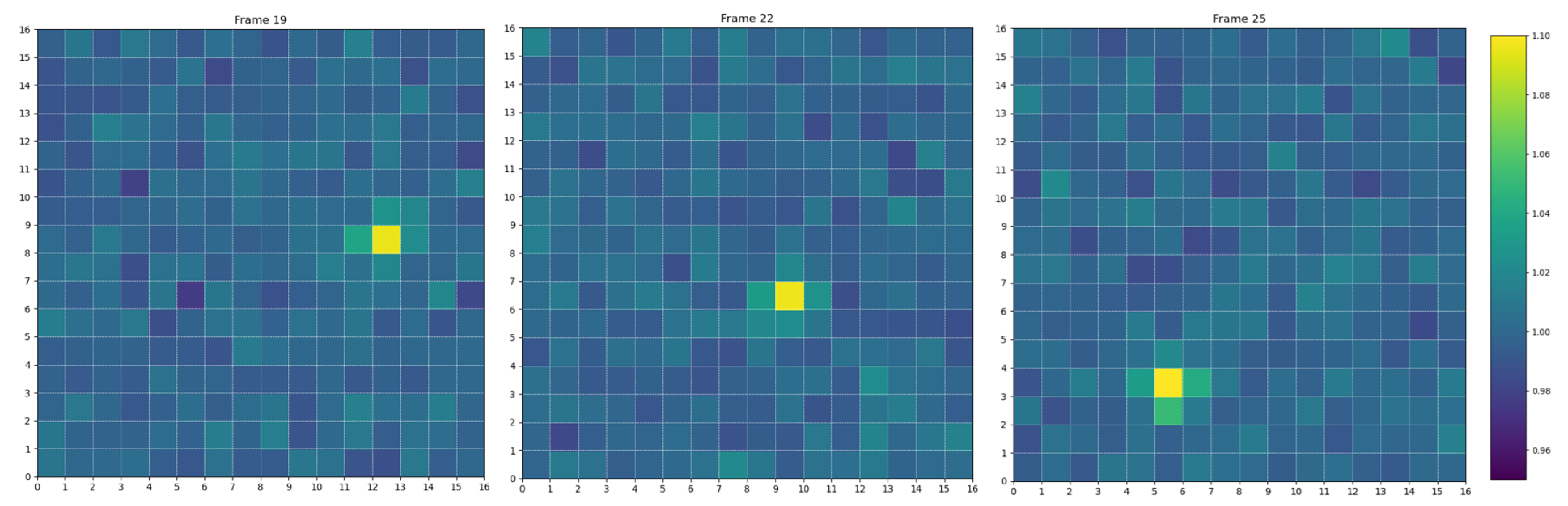
Figure 3.
Prototype Detector: (a) Front panel with Fresnel lens. (b) Back panel with external connectors. (c) Inner part showing the PDM, Zynq boards, and support electronics.
Figure 3.
Prototype Detector: (a) Front panel with Fresnel lens. (b) Back panel with external connectors. (c) Inner part showing the PDM, Zynq boards, and support electronics.
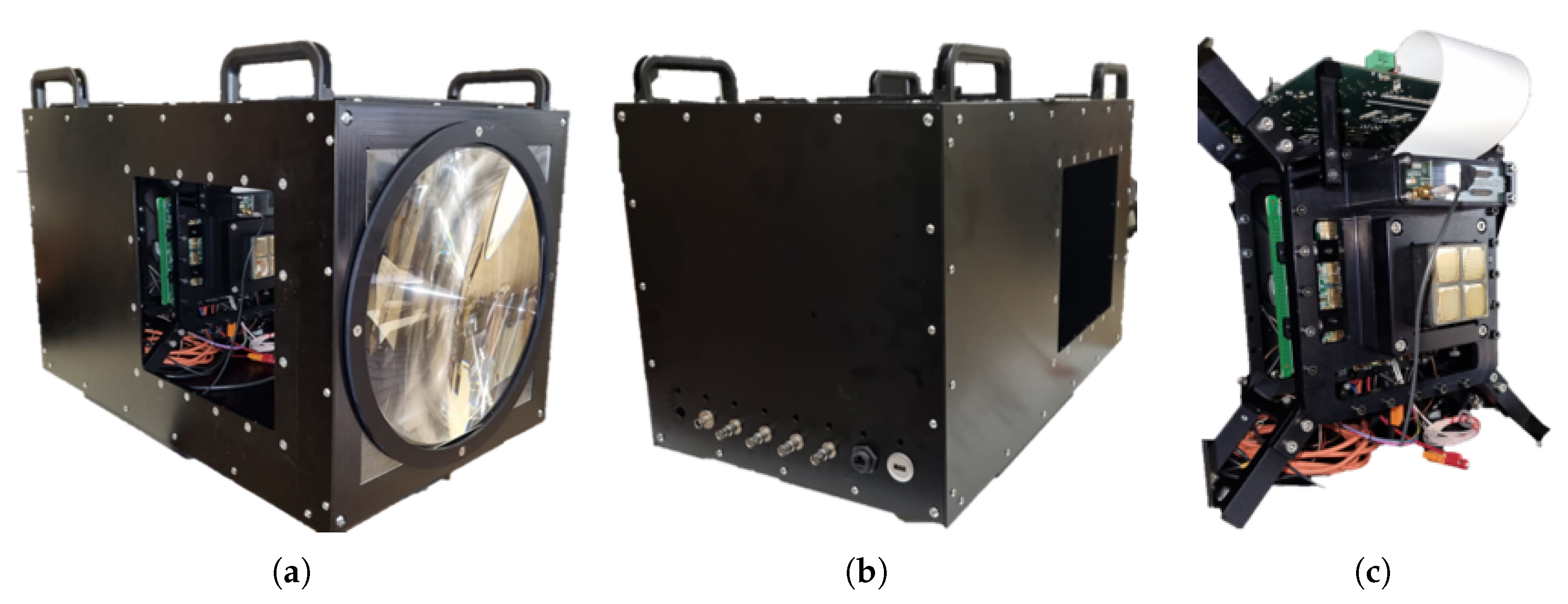
Figure 4.
Three frames acquired during an experimental observation campaign near Turin, showing a satellite pass detected by the prototype system. The object’s signal is visible above the background and moves consistently across the sensor’s pixels from frame to frame.
Figure 4.
Three frames acquired during an experimental observation campaign near Turin, showing a satellite pass detected by the prototype system. The object’s signal is visible above the background and moves consistently across the sensor’s pixels from frame to frame.
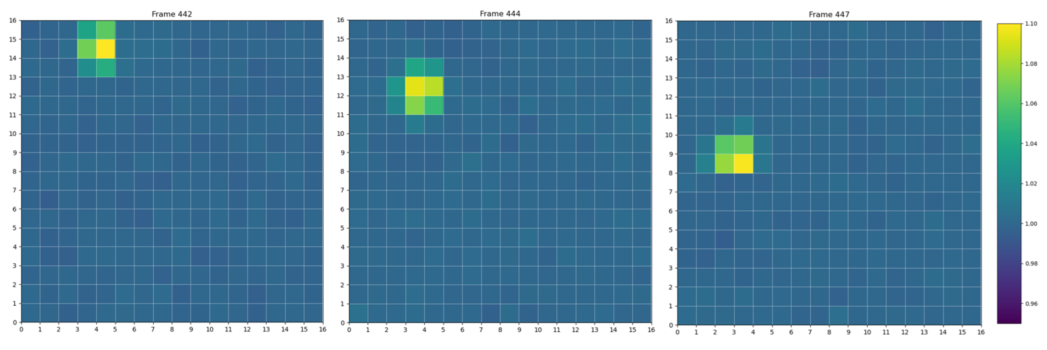
Figure 6.
Detection efficiency of the Stack-CNN trigger for 10 cm diameter debris as a function of binned distance intervals from 0 to 100 km. The system maintains over 60% efficiency up to 30 km, dropping below 50% beyond 40 km, and reaching negligible values after 50 km. The result reflects the decreasing signal-to-background ratio with distance, and offers a practical benchmark for the trigger’s effective range.

Figure 7.
Signal over background measured for 17 satellite passages detected with the prototype detector and processed with the Stack-CNN pipeline. The red line indicates the mean signal level (4%), and the blue line represents the estimated experimental detection limit (1.5%).
Figure 7.
Signal over background measured for 17 satellite passages detected with the prototype detector and processed with the Stack-CNN pipeline. The red line indicates the mean signal level (4%), and the blue line represents the estimated experimental detection limit (1.5%).
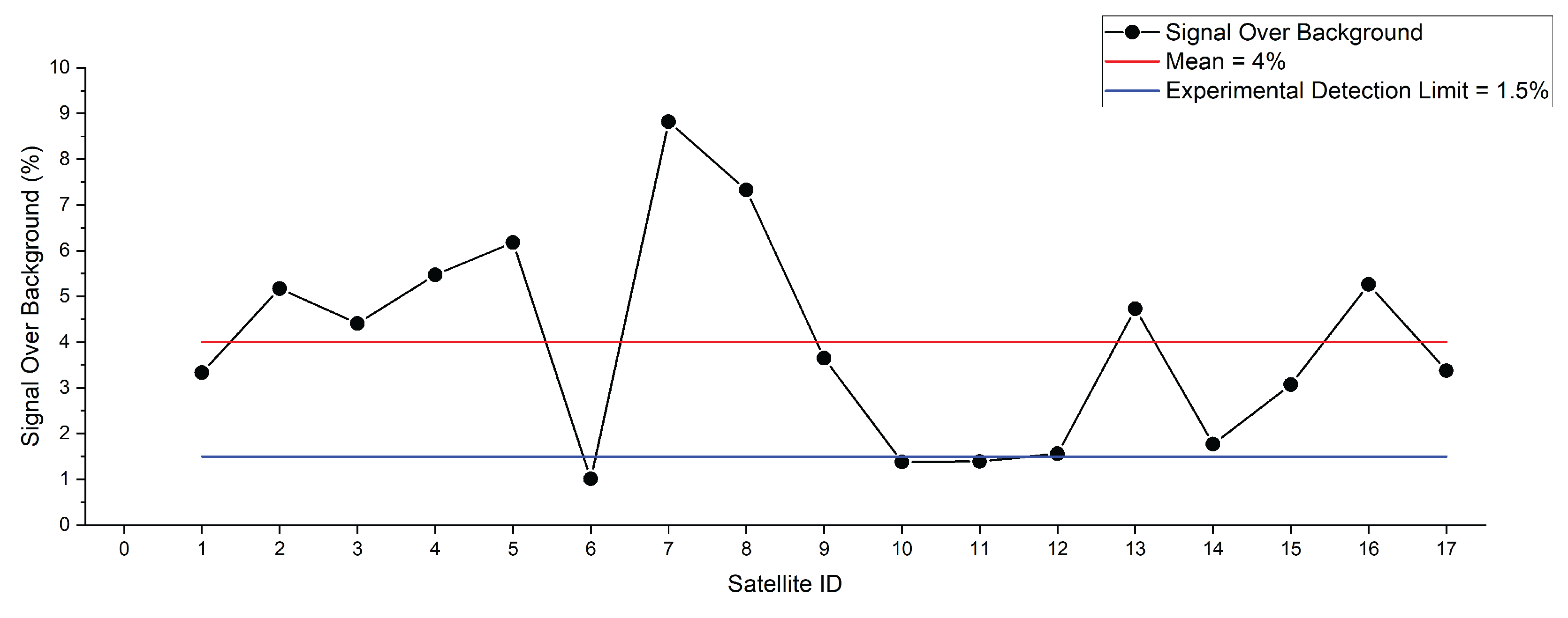
Table 2.
Comparison of model architectures for FPGA implementation.
| Property | Original Stack-CNN [5] | This Work (QAT-CNN) |
|---|---|---|
| Input size | ||
| Quantized (8-bit) | No | Yes |
| Training with QAT | No | Yes |
| Number of Conv Layers | 3 | 2 |
| Number of Dense Layers | 3 | 2 |
| Flattened feature size | 144 | 512 |
| Total parameters | ∼16,700 | 37,697 |
| FPGA pipelining friendly | Moderate | High |
Table 3.
Metadata summary of the exported ONNX model for the quantized Stack-CNN architecture, prepared for FPGA deployment via the Vitis AI toolchain.
Table 3.
Metadata summary of the exported ONNX model for the quantized Stack-CNN architecture, prepared for FPGA deployment via the Vitis AI toolchain.
| Property | Description | Value |
|---|---|---|
| IR Version | ONNX Intermediate Representation version | 6 |
| Producer | Exporting framework and version | PyTorch 2.3.0 |
| Opset Version | ONNX operator set version | 11 |
| Number of Nodes | Total operations in the ONNX graph | 11 |
| Number of Initializers | Trainable tensors (e.g., weights/biases) | 8 |
| Input Tensor Shape | Input dimensions (N, C, H, W) | (1, 1, 16, 16) |
| Output Tensor Shape | Output dimensions | (1, 1) |
Disclaimer/Publisher’s Note: The statements, opinions and data contained in all publications are solely those of the individual author(s) and contributor(s) and not of MDPI and/or the editor(s). MDPI and/or the editor(s) disclaim responsibility for any injury to people or property resulting from any ideas, methods, instructions or products referred to in the content. |
© 2025 by the authors. Licensee MDPI, Basel, Switzerland. This article is an open access article distributed under the terms and conditions of the Creative Commons Attribution (CC BY) license (http://creativecommons.org/licenses/by/4.0/).
Copyright: This open access article is published under a Creative Commons CC BY 4.0 license, which permit the free download, distribution, and reuse, provided that the author and preprint are cited in any reuse.


