
Submitted:
21 July 2025
Posted:
21 July 2025
You are already at the latest version
Abstract
This study focuses on the investigation of an innovative external strengthening technique for reinforced concrete (RC) beam–column joints, utilizing near-surface mounted (NSM) Carbon Fiber Reinforced Polymer (C-FRP (Carbon Fiber Reinforced Polymer)) ropes. The ropes are installed diagonally on both main faces of the joint, forming external X-shaped configurations. Additionally, vertical reinforcement is provided at the four corners of the column, with one rope placed per corner. Complementary strengthening is also applied to the beam’s plastic hinge region using externally bonded C-FRP (Carbon Fiber Reinforced Polymer) sheets. The proposed technique is based on the premise that the X-shaped diagonal ropes provide adequate confinement to the joint core and act effectively as shear reinforcement, thus mitigating the shear distortions typically developed in the joint area under seismic loading. At the same time, the use of C-FRP (Carbon Fiber Reinforced Polymer) sheets in the beam further enhances the load-bearing capacity of the joint, particularly in the region of plastic hinge formation. To evaluate the effectiveness of the technique, full-scale cyclic loading tests were conducted on three RC beam–column joint specimens. These specimens were specifically designed to concentrate damage within the joint core, simulating conditions of insufficient initial reinforcement. Comparative analysis between the strengthened and unstrengthened specimens clearly demonstrated that the external application of C-FRP (Carbon Fiber Reinforced Polymer) ropes significantly contributed to preserving the integrity of the joint region and reducing shear deformations, especially under large displacement demands. In particular, the specimen strengthened with both X-shaped C-FRP (Carbon Fiber Reinforced Polymer) ropes in the joint core and C-FRP (Carbon Fiber Reinforced Polymer) sheets on the beam (JB0VF2X2c+C-FRP (Carbon Fiber Reinforced Polymer)) exhibited a peak load increase of up to 65%, an enhancement in equivalent viscous damping of up to 55%, and a reduction in shear deformations exceeding 40%, compared to the unstrengthened specimen. Furthermore, improved energy dissipation capacity, better stiffness retention, and delayed damage progression were observed. Overall, the proposed strengthening approach using externally applied C-FRP (Carbon Fiber Reinforced Polymer) ropes and sheets emerges as an effective and practically applicable solution for retrofitting existing RC joints in seismic regions. It enhances both strength and ductility without altering the geometry or increasing the mass of the structural elements.
Keywords:
Strengthening of beam-columns
; FRP ropes
; shear deformations
; Near-surface mounted (NSM) technique
1. Introduction
Severe seismic events across the globe have repeatedly revealed the inadequate structural performance of many reinforced concrete (RC) buildings designed according to outdated codes and construction practices. A common deficiency observed in such structures is the insufficient or even total absence of transverse reinforcement in critical regions, often leading to extensive damage or complete structural collapse [1].
Among the most vulnerable structural components are the beam-column joints (BCJs), which are prone to early-stage damage under seismic loading. Inadequate reinforcement detailing in these joints has been closely linked to brittle failure modes, and in numerous instances, has contributed to partial or total structural failure [2,3].
Given the associated risks to public safety and the potentially catastrophic consequences of failure, the development of effective retrofitting and strengthening strategies for such critical elements remains a top research priority in structural engineering [4].
Traditionally, the most widespread strengthening technique involves concrete jacketing with additional conventional steel reinforcement. However, in recent decades, the use of advanced materials such as fiber-reinforced concrete and fiber-reinforced polymer (FRP) composites has gained prominence as a more effective solution for enhancing the seismic resistance of RC elements subjected to dynamic or repeated loading [1].
Each strengthening method requires a different level of specialization and presents varying degrees of disruption to the structure during application. The use of externally bonded FRP sheets, for example, offers a faster and more straightforward installation process compared to conventional jacketing [5]. Nevertheless, ensuring proper anchorage of the FRP sheets remains a critical issue, as highlighted in experimental studies involving U-wrap configurations [6].
Numerous studies in the literature have explored state-of-the-art FRP-based strengthening strategies for BCJs subjected to cyclic loading [7]. In addition to surface-bonded FRP sheets, the near-surface mounted (NSM) technique using either FRP or steel elements has also been extensively investigated. Other innovative retrofitting solutions include external steel plates, supplemental bars, welded wire meshes, and haunch-type reinforcements. These approaches are often supported by analytical and numerical modeling efforts [8].
Among the promising alternatives to steel reinforcement are FRP bars made of carbon fibers, which offer advantages such as high tensile strength, low weight, and superior corrosion resistance [1]. More recently, flexible carbon FRP (C-FRP (Carbon Fiber Reinforced Polymer)) ropes have been experimentally investigated as externally applied reinforcement for BCJs, demonstrating significant practical benefits and strengthening effectiveness [9,22].
2. Design Purpose of the Joint Specimens
2.1. Characteristics of Specimens—Materials
The geometry, materials, and reinforcement details (Table 1) of the tested subassemblages were designed to reflect the typical characteristics of reinforced concrete (RC) frame elements commonly found in standard building structures. The column had a total length of 3.0 m and a cross-section of 350/250 mm, while the beam measured 1.875 m in length, also with a 350/250 mm cross-section. The geometrical configuration and reinforcement details of specimens JB0V, JB0VF2X2c, and JB0VF2X2c + C-FRP Sheets are identical and are presented in Figure 1a–c.
The objective of this research was to evaluate the effectiveness of applying externally bonded C-FRP (Carbon Fiber Reinforced Polymer) ropes, arranged diagonally on both sides of the beam–column joint (BCJ), with the dual purpose of:
- (i)
- supplementing the longitudinal and transverse reinforcement of the column, and
- (ii)
For this purpose, specimen JB0VF2X2c was strengthened using externally applied C-FRP (Carbon Fiber Reinforced Polymer) ropes implemented through the Near-Surface Mounted (NSM) technique at the following locations:
- (a)
- longitudinal tensile reinforcement along each corner of the column height,
- (b)
- transverse confining reinforcement around the column in the critical regions near the joint, and
- (c)
Specimen JB0VF2X2c + CFRP Sheets was similarly reinforced on the column using C-FRP (Carbon Fiber Reinforced Polymer) ropes at the same positions as above, and additionally, the beam was strengthened with externally bonded C-FRP (Carbon Fiber Reinforced Polymer) sheets [9]. The complete strengthening layout is illustrated in Figure 1c.
The compressive strength of the concrete was determined through compression tests on six standard cylindrical specimens (150 × 300 mm), yielding an average compressive strength of fcm = 34 MPa. The reinforcing steel used was of grade B500C, with an average tensile strength of fy = 550 MPa.
The C-FRP (Carbon Fiber Reinforced Polymer) rope consisted of a bundle of unidirectional carbon fibers, with the following properties: tensile strength of 4000 MPa, modulus of elasticity of 240 GPa, and cross-sectional area greater than 28 mm2, according to the manufacturer’s specifications (SikaWrap® FX-50C and SikaWrap® FX Fibre Connector, SIKA HELLAS SA, Kryoneri, Attica, Greece) [1].
Two types of epoxy resin were used for the strengthening system:
- -
- Resin type A (Sikadur®-52) for the impregnation of the dry fibers,
- -
- Resin type B (Sika AnchorFix®-3+) for anchoring the C-FRP ropes to the concrete sub-strate [4].
Mechanical properties of the applied C-FRP sheet:
- S&P C-Sheets 240: thickness tf = 0.168 mm,
- tensile strength ff = 4300 MPa,
- elastic modulus Eft = 240 GPa,
- fracture tensile strain = 1.7%.
- Properties of the epoxy adhesive paste:
- S&P Resin 55 HP:
- compressive strength = 100 MPa,
- elastic modulus = 3.2 GPa.
2.2. External Installation of the Strengthening C-FRP Ropes
The retrofitting procedure involving the use of C-FRP (Figure 1b,c) ropes required strict adherence to predefined, high-precision steps [5]. Initially, guiding lines were drawn on the concrete surface to define the exact insertion paths for the ropes. These lines facilitated the accurate cutting of U-shaped grooves, typically measuring 20 mm in depth and 20 mm in width. Subsequently, a thorough cleaning of the grooves was carried out using compressed air to eliminate any dust or debris that could compromise the bonding performance. In accordance with the manufacturers’ technical specifications [4], the outer edges of the grooves were rounded to a minimum radius of 20 mm, in order to mitigate localized stress concentrations. During the intervention, appropriate measures were taken to protect the existing steel reinforcement and stirrups from accidental damage during the mechanical cutting process. Special attention was also paid to the proper placement and anchorage of each C-FRP (Carbon Fiber Reinforced Polymer) rope, ensuring the effective performance of the strengthening system [7].
2.3. Examination of the Expected Damage
In order to assess the potential extent and distribution of damage in the tested beam–column joint specimens, a numerical approach was employed, based on a well-established theoretical framework proposed by Tsonos [10]. This method allows for the estimation of the ultimate shear strength τult, as well as the corresponding shear capacity ratio γult, defined as . This value is subsequently compared with the calculated ratio , which reflects the actual shear demand under the applied loading conditions.
The analysis of the examined specimens indicated that, in cases where γcal is significantly lower than γult, the expected damage is concentrated in the beam, while the joint core remains unaffected. Conversely, when the two values are close, the formation of cracking is likely to occur both in the beam and within the joint region.
These predictions were confirmed by the results of the experimental testing.
This study examines three specimens. Specimen JB0V serves as the primary reference for comparative evaluation. In specimen JB0VF2X2c, the column was externally strengthened with C-FRP ropes, while in JB0VF2X2c + C-FRP Sheets, both the column (with C-FRP ropes) and the beam (with C-FRP sheets) were strengthened [2,9].
Additionally, specimens JB0VF2X2c and JB0VF2X2c + C-FRP were reinforced with diagonally arranged X-type C-FRP ropes embedded in the joint core (see Figure 1b), aiming to enhance the shear capacity of the beam–column joint system [3]. The analysis and comparison of shear deformations recorded in the individual specimens provide insight into the effectiveness of X-type reinforcement in improving the joint’s shear performance.
To investigate the behavior of substandard joints externally strengthened with C-FRP ropes, the specimens were purposely designed to allow the development of cracks and localized failures within the joint core [10].
The maximum shear force transferred to the joint through the four tension reinforcement bars of the beam (14 mm in diameter) was calculated as Vjhd = 320 kN, corresponding to a shear stress of τ = 3.67 MPa. Furthermore, for the tested specimens, the ratio ΣMc/MRb was determined to be 1.43. According to the ACI 318 code [11], external joints must satisfy the condition ΣMc/MRb > 1.40. Since the calculated value of 1.43 is only slightly above the critical threshold, it is considered reasonable to expect cracking not only in the beam but also within the joint region.
3. Test Setup and Measurement of Shear Deformations
3.1. Test setup
The experimental setup and instrumentation details are illustrated in Figure 2. During testing, each subassembly was rotated by 90°, positioning the beam vertically and the column horizontally. To replicate realistic boundary conditions of laterally loaded RC frames, rotational end restraints were introduced at the column ends, simulating inflection points at mid-span [12,13]. A constant axial compressive load Nc, corresponding to 5% of the column’s axial capacity (0.05Acfc), was applied and carefully maintained at 150 kN for the full duration of the loading process across all specimens [14].
3.2. Loading Sequence
The loading protocol applied to the specimens is illustrated in Figure 3 [15,16]. The structural response was evaluated using the Story Drift (SD) index, defined as the ratio between the imposed displacement and the effective length of the beam measured from the point of loading to the centerline of the column. For each loading stage, the drift was calculated based on the measured deformation Δℓ and the reference length, according to the following expression: SD = Δℓ/(ℓb+hc/2) = Δℓ/(1,525+0,35/2) = Δℓ/1700 mm. The predefined cyclic loading sequence included seven successive deformation levels: 8.50 mm, 12.75 mm, 17.00 mm, 25.50 mm, 34.00 mm, 51.00 mm, and 68.00 mm, which corresponded to story drift values of 0.50%, 0.75%, 1.00%, 1.50%, 2.00%, 3.00%, and 4.00%, respectively. Each loading level consisted of three full cycles, as illustrated in Figure 3 [17,21].
4. Test Results and Hysteretic Responses
The analysis of the hysteresis curves (P–D) [10,18,24], of specimens JB0V, JB0VF2X2c, and JB0VF2X2c+CFRP highlights clear distinctions in their mechanical behavior under cyclic loading, with respect to load-bearing capacity, deformability, and stiffness. A comparative assessment of the results follows:
Figure 4.
Hysteretic responses of the specimens. Comparative depiction of the pilot specimen with the corresponding retrofitted ones.
Figure 4.
Hysteretic responses of the specimens. Comparative depiction of the pilot specimen with the corresponding retrofitted ones.
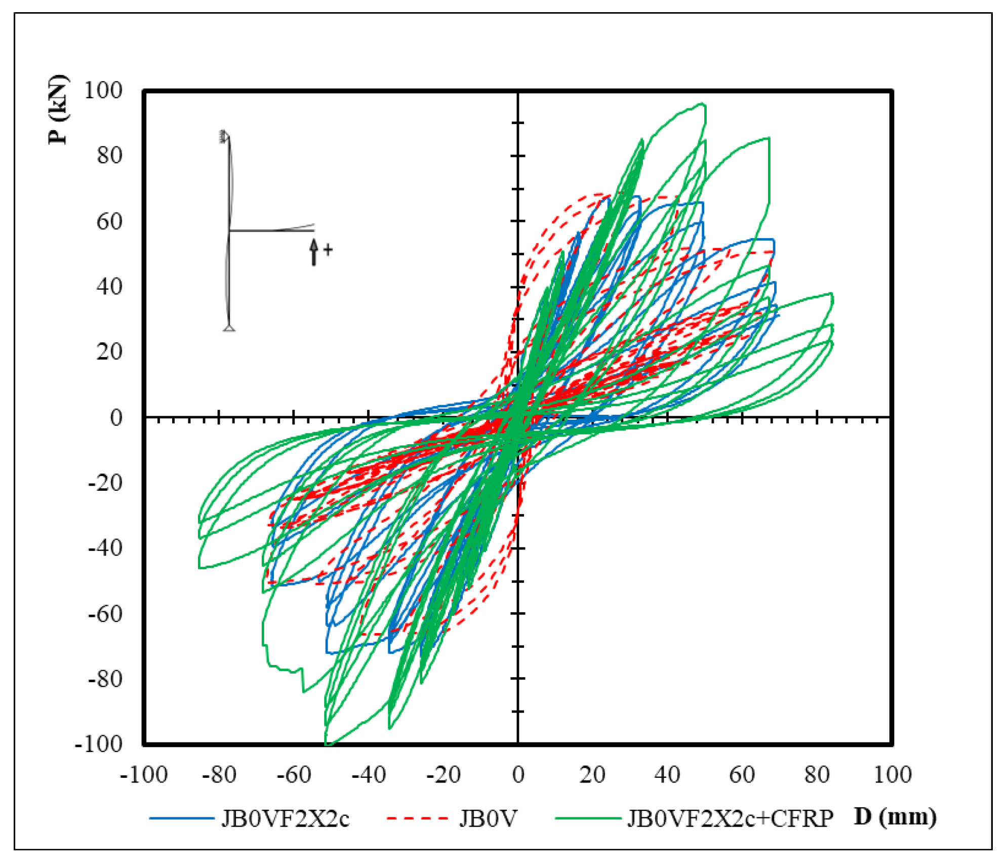
The JB0V specimen, serving as the control specimen, demonstrated significantly lower load-bearing capacity, with reduced peak load (P) values in both positive and negative directions. The hysteresis loops appear narrow, indicating limited energy dissipation capability and low ductility. Furthermore, early degradation of load resistance was observed as the loading cycles progressed.
In the JB0VF2X2c specimen, which was retrofitted with X-type C-FRP ropes embedded within the joint and anchored along the column edges (one rope per corner), a significantly enhanced mechanical response was observed. The load-bearing capacity was notably higher compared to the JB0V specimen, while the hysteresis loops were wider and more effective in dissipating energy [9]. The specimen exhibited improved deformability without abrupt strength degradation, and the resistance distribution remained consistent throughout the deformation range [25].
The JB0VF2X2c + C-FRP specimen incorporated combined strengthening, with both X-type C-FRP ropes at the joint and vertical ropes along the column, in addition to externally bonded C-FRP sheets along the beam. This configuration resulted in optimal overall performance [2,19]. The highest peak loads were recorded, reaching up to ±90 kN, and the hysteresis loops were broader and denser, indicating superior energy dissipation capacity. The structural system exhibited high ductility and retained mechanical integrity under repeated seismic-type loading. Moreover, the delay in stiffness degradation further confirmed the effectiveness of the applied retrofitting scheme [20,23,26].
In summary, the use of X-type C-FRP ropes (JB0VF2X2c) improved by over 40% the shear behavior compared to the unstrengthened specimen. The additional beam strengthening with externally bonded C-FRP sheets (JB0VF2X2c+CFRP) further enhanced the system’s overall capacity and deformability. The general shape of the hysteresis loops suggests that the retrofitted specimens are better suited to withstand repeated seismic actions, offering increased safety margins and reduced mechanical deterioration over time.
At the final loading stage (Step 7), the observed damage patterns revealed significant differences in the structural performance of the three specimens. For the reference specimen JB0V (Figure 5a), severe material degradation was evident in the joint core, with pronounced concrete crushing and spalling. The specimen experienced complete shear failure, as indicated by irregular and discontinuous diagonal cracking across the joint region. The cracks were widespread and dense in both the beam and the joint body, signifying severe to extensive structural damage. The absence of any confinement or reinforcement mechanism led to low energy dissipation and poor ductility.
Specimen JB0VF2X2c, which was strengthened with internal X-shaped C-FRP ropes within the joint and vertical ropes along the column edges (Figure 5b), exhibited a notably improved damage profile. Cracking was reduced and more uniformly distributed. The reinforcement configuration appeared effective in controlling the progression of shear failure. No signs of concrete crushing, material loss, or delamination were recorded. The joint maintained its integrity, and the damage level was assessed as minor to moderate.
In specimen JB0VF2X2c + C-FRP, where a combined retrofit strategy was applied—including internal C-FRP X-ropes and vertical ropes along the column, as well as externally bonded C-FRP sheets on the beam (Figure 5c)—the structure remained largely undamaged. The surface showed no visible diagonal cracks or distress, and the element preserved its cohesion. The combined retrofit ensured excellent confinement and integrity, with the C-FRP sheet on the column significantly contributing to stiffness retention and damage suppression. The overall damage level was classified as negligible.
In conclusion, the progressive application of retrofit techniques from specimen JB0V to JB0VF2X2c + C-FRP resulted in a clear enhancement in mechanical behavior and substantial reduction in joint and beam damage. The use of X-shaped C-FRP ropes in JB0VF2X2c provided significant improvement over the unretrofitted control specimen, while the additional application of bonded C-FRP sheets on the beam in JB0VF2X2c + C-FRP led to optimum seismic performance, preserving the structural integrity even under the most demanding cyclic loading conditions. The fully retrofitted system demonstrated enhanced resilience, superior energy dissipation, and increased seismic reliability.
The following four diagrams illustrate the cyclic loading behavior of the specimens, presenting the maximum applied force (P) as a function of the relative displacement (Story Drift—SD). The assessment at each loading stage is summarized below:
Figure 6.
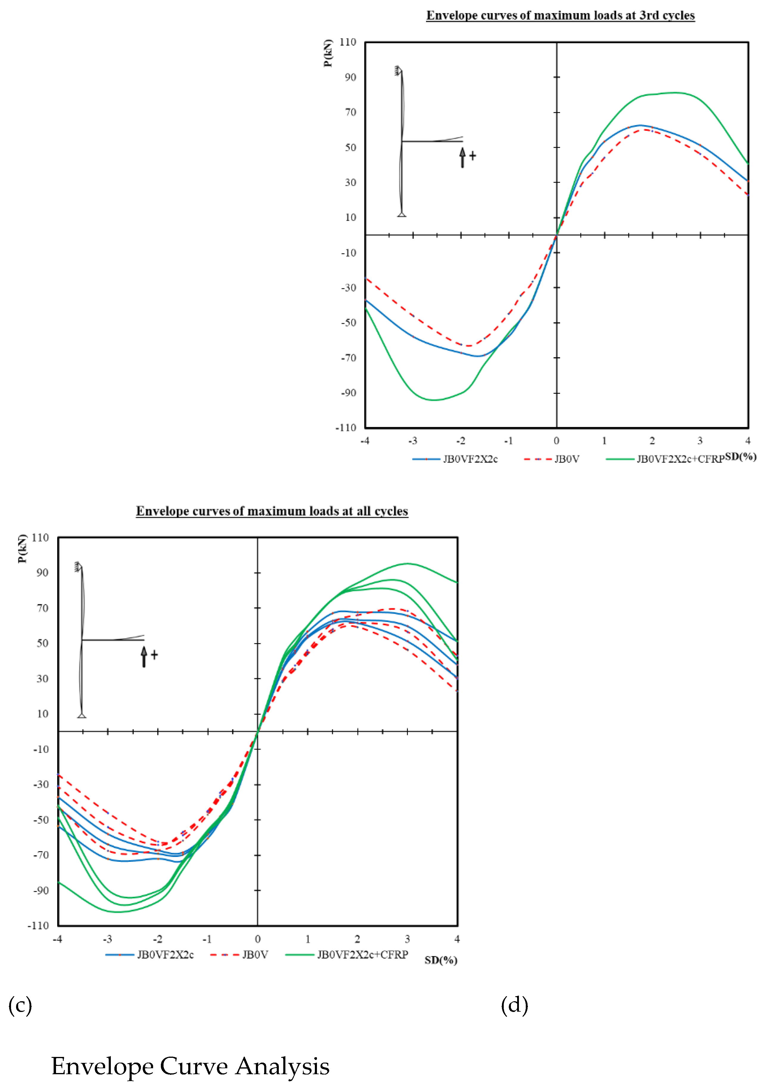
Envelope curves of the hysteretic responses. Specify: First (a), second (b), third (c), and cumulative (d) cycles, showing load vs. story drift (%) for each specimen (JB0V, JB0VF2X2c, JB0VF2X2c + C-FRP).
Figure 6.
Envelope curves of the hysteretic responses. Specify: First (a), second (b), third (c), and cumulative (d) cycles, showing load vs. story drift (%) for each specimen (JB0V, JB0VF2X2c, JB0VF2X2c + C-FRP).
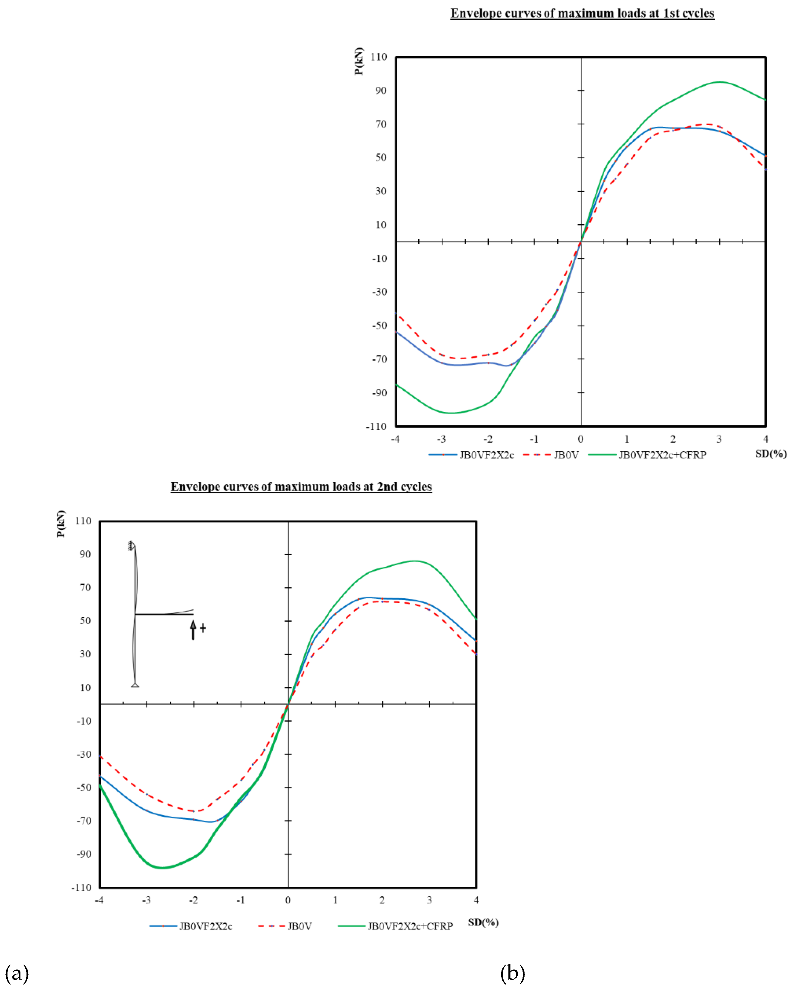
The cyclic load-displacement response of the three tested specimens reveals distinct differences in structural performance, as illustrated by the evolution of their envelope curves. The fully strengthened specimen JB0VF2X2c + C-FRP consistently demonstrates the highest load-bearing capacity, achieving peak forces of approximately ±90 kN in both tension and compression, already from the first loading cycle (Figure 6a). This highlights the substantial improvement in strength and ductility due to the combined use of X-type C-FRP rope reinforcement within the joint and external C-FRP sheets along the beam.
The JB0VF2X2c specimen, reinforced with X-type ropes only, also displays a markedly improved response compared to the unstrengthened reference specimen JB0V, particularly for story drift values exceeding 1%. In contrast, JB0V exhibits lower strength, with a premature reduction in force capacity as deformation increases, indicating limited energy dissipation and early stiffness degradation.
As the cyclic loading progresses, these trends become even more evident. In the second cycle (Figure 6b), JB0VF2X2c+CFRP continues to perform without noticeable degradation, maintaining high resistance across the full drift range. The divergence between the envelope curves of the strengthened and unstrengthened specimens increases significantly. JB0V shows a progressive decline, particularly under negative displacements, consistent with cumulative internal damage.
During the third loading cycle (Figure 6c), JB0VF2X2c + C-FRP preserves its dominant performance, demonstrating a high tolerance to repeated loading and effective confinement of structural deterioration. JB0VF2X2c maintains a stable load-displacement profile, while JB0V further deteriorates, with clear evidence of stiffness loss and reduced residual strength.
When examining the overall cumulative response across all cycles (Figure 6d), the envelope curve of JB0VF2X2c + C-FRP is clearly separated from the other two, indicating superior seismic behavior. This specimen not only achieves higher peak forces but also retains its strength at large displacements, reflecting enhanced ductility and energy dissipation capacity. JB0VF2X2c also maintains consistent performance throughout the loading history. Conversely, JB0V exhibits a significantly narrower force range, rapid strength degradation, and poor hysteretic performance, confirming its unsuitability for seismic applications.
Finally, the comparative envelope analysis highlights the clear benefits of progressive strengthening. The unstrengthened specimen JB0V suffered early degradation, limited deformation capacity, and poor energy dissipation under cyclic demands, rendering it structurally vulnerable in seismic conditions.
The implementation of X-type C-FRP rope reinforcement in JB0VF2X2c led to significant gains in both load-bearing capacity and deformation tolerance.
The JB0VF2X2c + C-FRP specimen, incorporating combined strengthening of both joint and beam, delivered the most robust performance across all metrics — strength, ductility, stiffness retention, and cyclic energy dissipation.
Overall, the results confirm that C-FRP-based strengthening techniques, especially when combining internal ropes and external sheets, offer a highly effective retrofit strategy for critical RC beam-column joints, significantly improving their seismic resilience and ensuring enhanced safety for existing structures subjected to earthquake loading.
The following diagrams present the dissipated energy [28] per loading cycle (1st, 2nd, and 3rd) as a function of the story drift ratio (SD (%)) for three specimens: JB0V, JB0VF2X2c, and JB0VF2X2c + C-FRP.
Figure 7.
Comparative dissipated energy per cycle (1st, 2nd, 3rd) as a function of story drift for each specimen.
Figure 7.
Comparative dissipated energy per cycle (1st, 2nd, 3rd) as a function of story drift for each specimen.
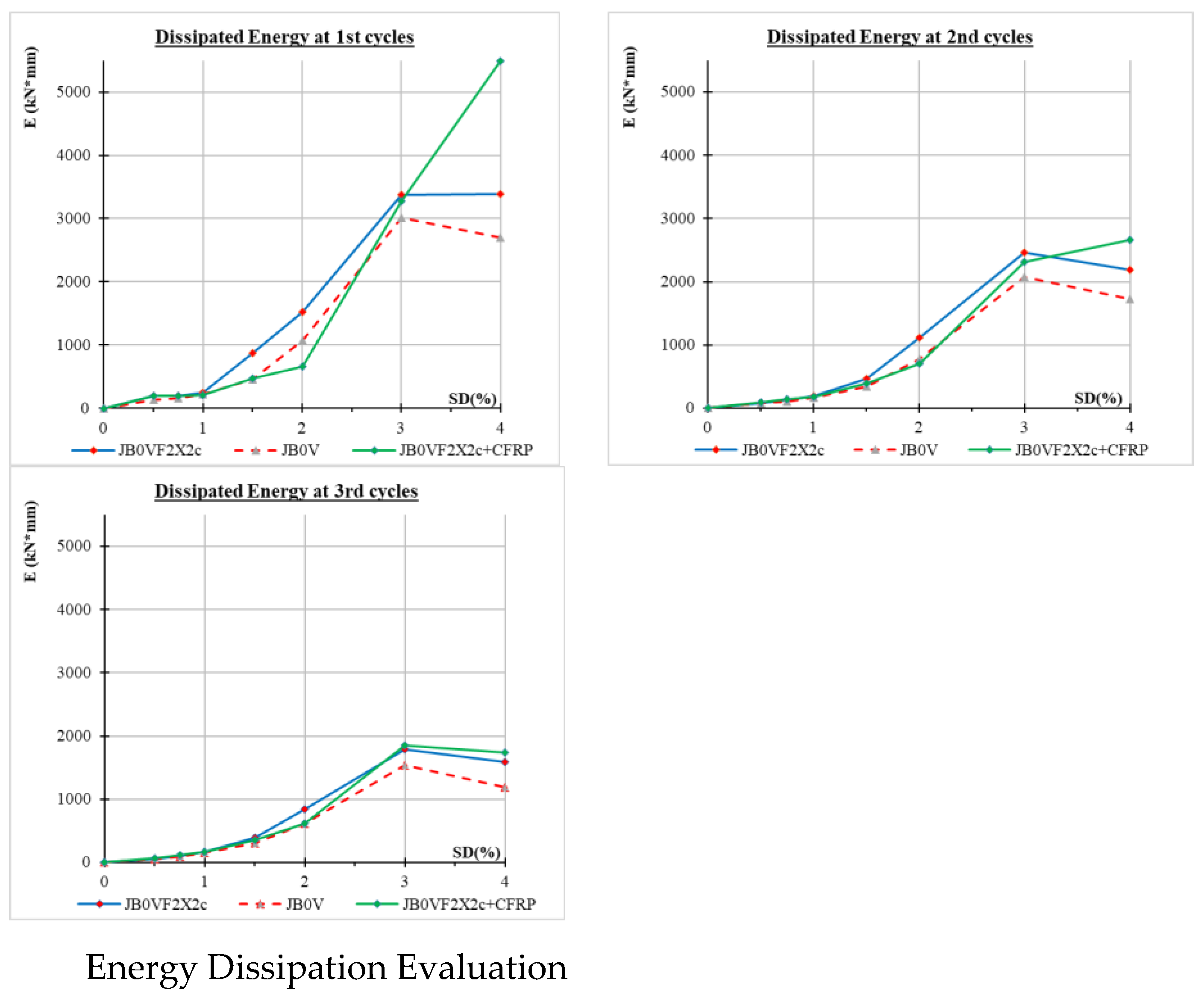
The analysis of the dissipated energy (E) diagrams for the first three loading cycles clearly highlights the positive effect of strengthening techniques on the energy absorption capacity of the specimens under cyclic loading. In the first cycle, specimen JB0VF2X2c + C-FRP, strengthened with C-FRP ropes on the column and C-FRP sheets on the beam, exhibits significantly superior performance, achieving the highest values of dissipated energy, particularly for deformations (SD) exceeding 2%. This specimen outperforms both the pilot specimen JB0V and JB0VF2X2c, which includes only limited reinforcement with C-FRP ropes on the column, thus demonstrating the contribution of C-FRP to the enhancement of the energy dissipation capacity [28].
During the second cycle, an overall reduction in dissipated energy is observed, indicating the effects of cyclic loading and the gradual degradation of the mechanical properties of the specimens. Nevertheless, JB0VF2X2c + C-FRP continues to maintain a comparative advantage, especially at higher SD levels, confirming the improved durability of the strengthened section [28].
In the third cycle, the deterioration of the specimens becomes more evident, with a further decrease in dissipated energy across all cases. Specimen JB0V shows a significant loss of energy dissipation capacity, whereas the strengthened specimens particularly JB0VF2X2c + C-FRP still absorb higher levels of energy, underscoring the role of the applied reinforcements in delaying degradation.
Overall, the use of C-FRP ropes and C-FRP sheets offers significant advantages in managing dissipated energy under seismic loading, enhancing both the stiffness and long-term durability of the section under repeated load cycles.
The following diagrams illustrate the variation of stiffness (K) of the specimens per loading cycle as a function of the story drift ratio (SD(%)).
Figure 8.
Stiffness (K) as a function of story drift per cycle. Comparison between pilot and strengthened specimens during 1st, 2nd, and 3rd loading cycles.
Figure 8.
Stiffness (K) as a function of story drift per cycle. Comparison between pilot and strengthened specimens during 1st, 2nd, and 3rd loading cycles.
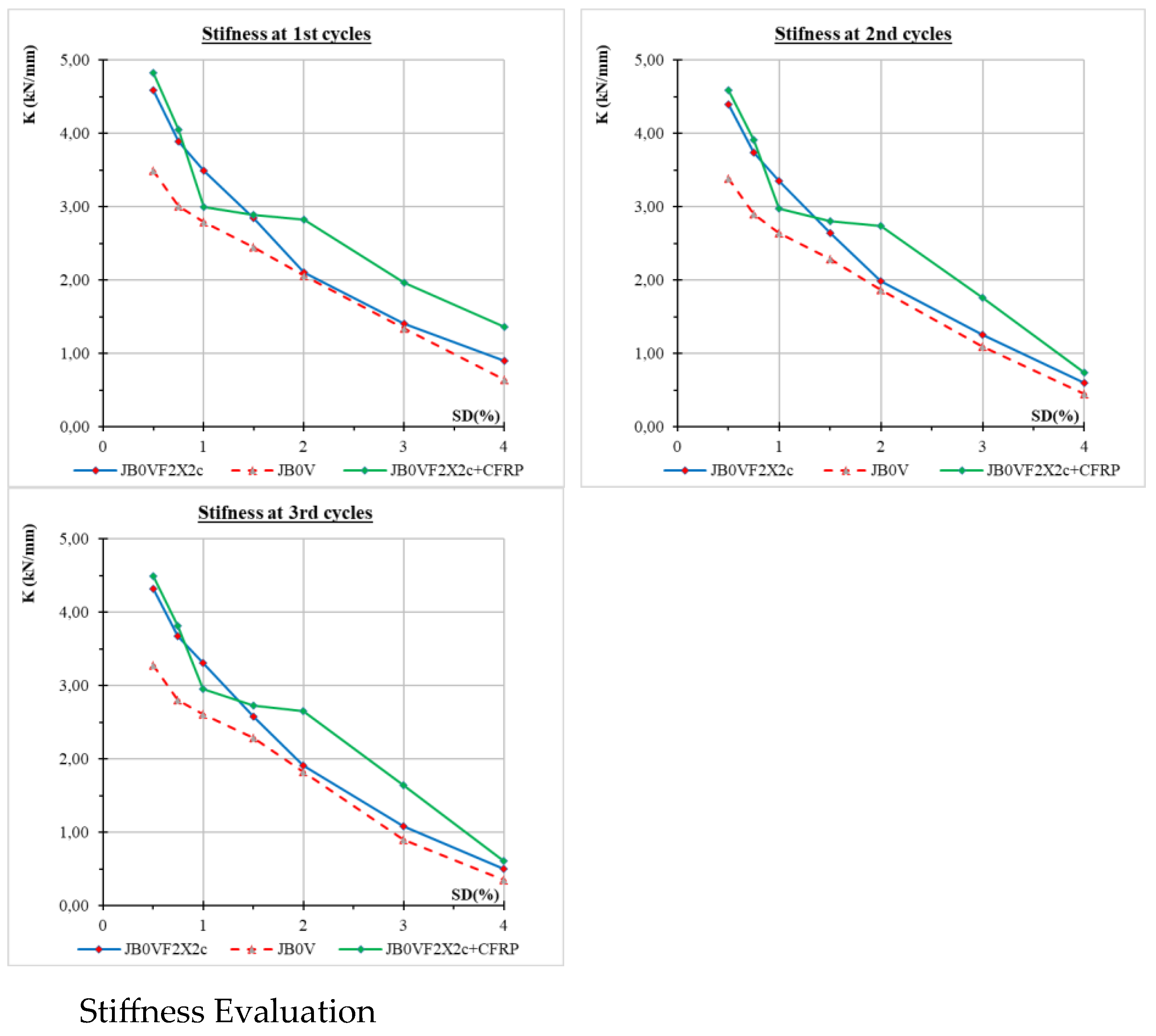
The analysis of the stiffness (K) diagrams for the first three loading cycles reveals the gradual reduction in the stiffness of the specimens with increasing story drift ratio (SD%), a trend that is expected due to the development of cracking and the progressive degradation of mechanical properties under cyclic loading. In the first cycle, the strengthened specimen JB0VF2X2c + C-FRP, which is reinforced with C-FRP ropes on the column and C-FRP sheets on the beam, exhibits the highest initial stiffness, exceeding 4.5 kN/mm, and maintains higher values throughout the deformation range [30]. The specimen JB0VF2X2c, which is reinforced only with C-FRP ropes on the column, shows slightly lower stiffness, while the pilot specimen JB0V consistently exhibits the lowest values, confirming the beneficial effect of the strengthening on the overall stiffness of the system.
During the second loading cycle, a further reduction in stiffness is observed across all three specimens. However, JB0VF2X2c + C-FRP retains its advantage, particularly at higher SD values. The specimen JB0VF2X2c follows with intermediate values, while JB0V continues to lag behind, recording lower stiffness values at all deformation levels. In the third cycle, degradation becomes more pronounced. The stiffness of all specimens drops significantly; nevertheless, the strengthened specimen JB0VF2X2c + C-FRP continues to demonstrate an increased ability to retain stiffness compared to the others. In contrast, JB0V exhibits nearly zero stiffness at 4% SD, indicating a complete loss of load-bearing capacity.
Overall, the use of composite C-FRP strengthening materials whether in the form of ropes or sheets contributes significantly to the increase and retention of stiffness in structural elements under cyclic loading. The application of such strengthening techniques proves particularly effective in enhancing the seismic performance and overall resilience of structures subjected to repeated loading.
Below are the diagrams illustrating the evolution of the damage index as a function of the story drift ratio (SD%) for the first three loading cycles.
Figure 9.
Damage index evolution per cycle and per drift step for all specimens. Highlight first, second, and third loading cycles.
Figure 9.
Damage index evolution per cycle and per drift step for all specimens. Highlight first, second, and third loading cycles.
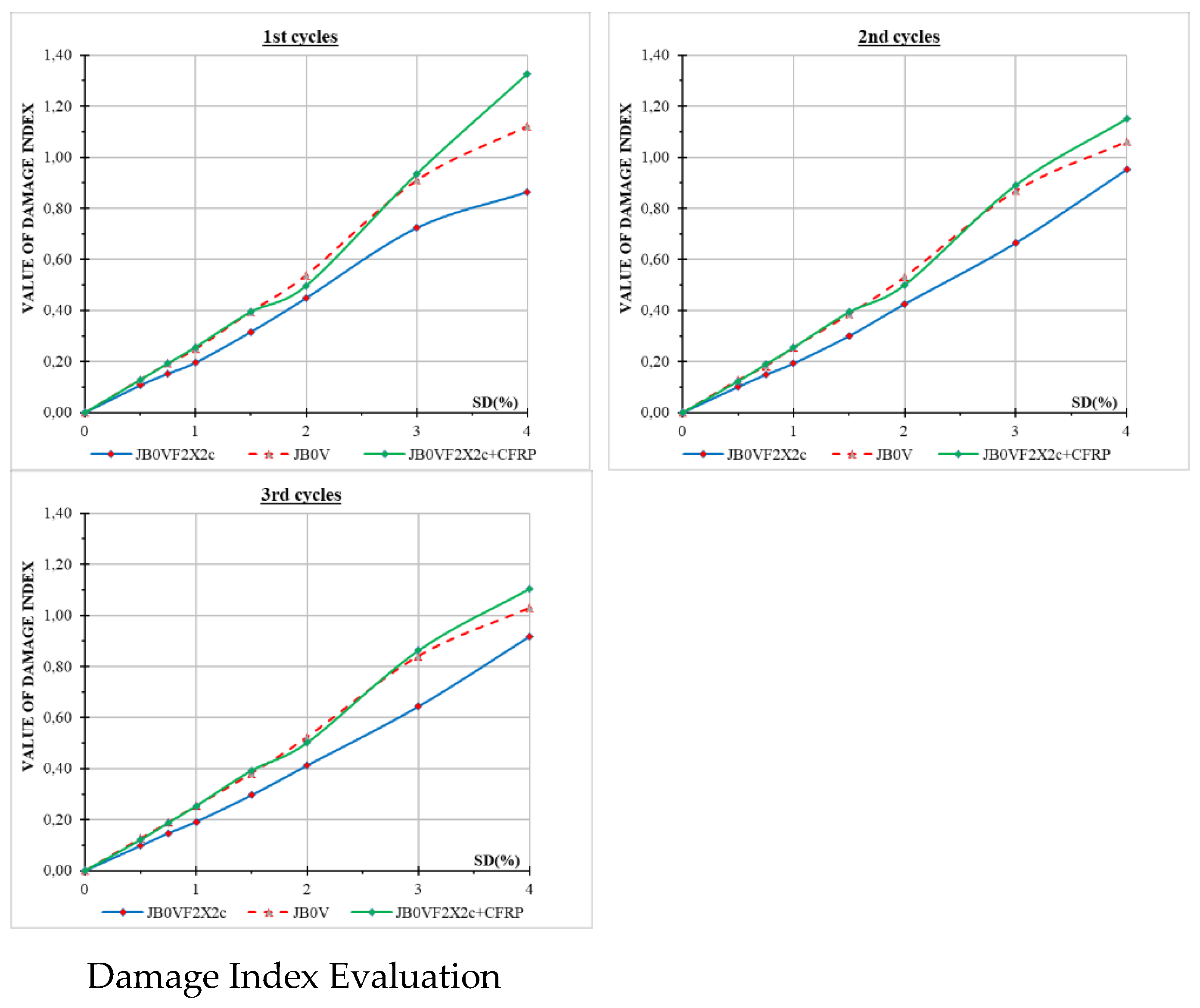
The analysis of the diagrams illustrating the evolution of the damage index in relation to the story drift ratio (SD%) over the first three loading cycles reveals the progressive deterioration of the specimens under cyclic loading. As expected, the damage index increases gradually with increasing SD across all specimens, reflecting the ongoing accumulation of damage [27] within the cross-section.
During the first cycle, the strengthened specimen JB0VF2X2c + C-FRP exhibits the highest damage index values, particularly for drift levels exceeding 2.5%. This behavior does not indicate inferior performance, but rather corresponds to the specimen’s enhanced energy dissipation capacity, which is accompanied by more pronounced local deformations. JB0V follows with slightly lower values, while JB0VF2X2c maintains the lowest rate of increase, indicating a more uniform and controlled damage progression at this stage.
In the second cycle, damage index values rise significantly for all specimens. JB0VF2X2c + C-FRP continues to record the highest values, following the same trend as in the first cycle. JB0V approaches the CFRP-strengthened specimen, suggesting an accelerated degradation rate of its cross-section, whereas JB0VF2X2c shows a relatively more restrained increase.
By the third cycle, deterioration becomes more pronounced. The damage index for all specimens reaches values between 1.0 and 1.2, indicating severe damage. JB0VF2X2c + C-FRP continues to exhibit the highest values, possibly due to concentrated damage in localized areas, despite its superior energy dissipation and retained stiffness. JB0V follows, having reached critical damage levels, confirming the more rapid exhaustion of its load-bearing capacity. JB0VF2X2c appears to be the most “resilient” in terms of overall damage, maintaining the lowest values.
In summary, the increased damage index observed in JB0VF2X2c + C-FRP does not necessarily indicate structural failure, but rather as a consequence of the higher stress levels associated with its improved energy performance. In contrast, JB0V deteriorates more rapidly and reaches critical states earlier, emphasizing the importance of strengthening techniques in delaying damage progression.
Below is the interpretation of the results from the diagram that illustrates the variation of equivalent viscous damping (%) as a function of story drift ratio (SD%) for specimens JB0V, JB0VF2X2c, and JB0VF2X2c + C-FRP.
Figure 10.
Equivalent viscous damping vs. story drift (%) for pilot and strengthened specimens (JB0V, JB0VF2X2c, JB0VF2X2c + C-FRP).
Figure 10.
Equivalent viscous damping vs. story drift (%) for pilot and strengthened specimens (JB0V, JB0VF2X2c, JB0VF2X2c + C-FRP).
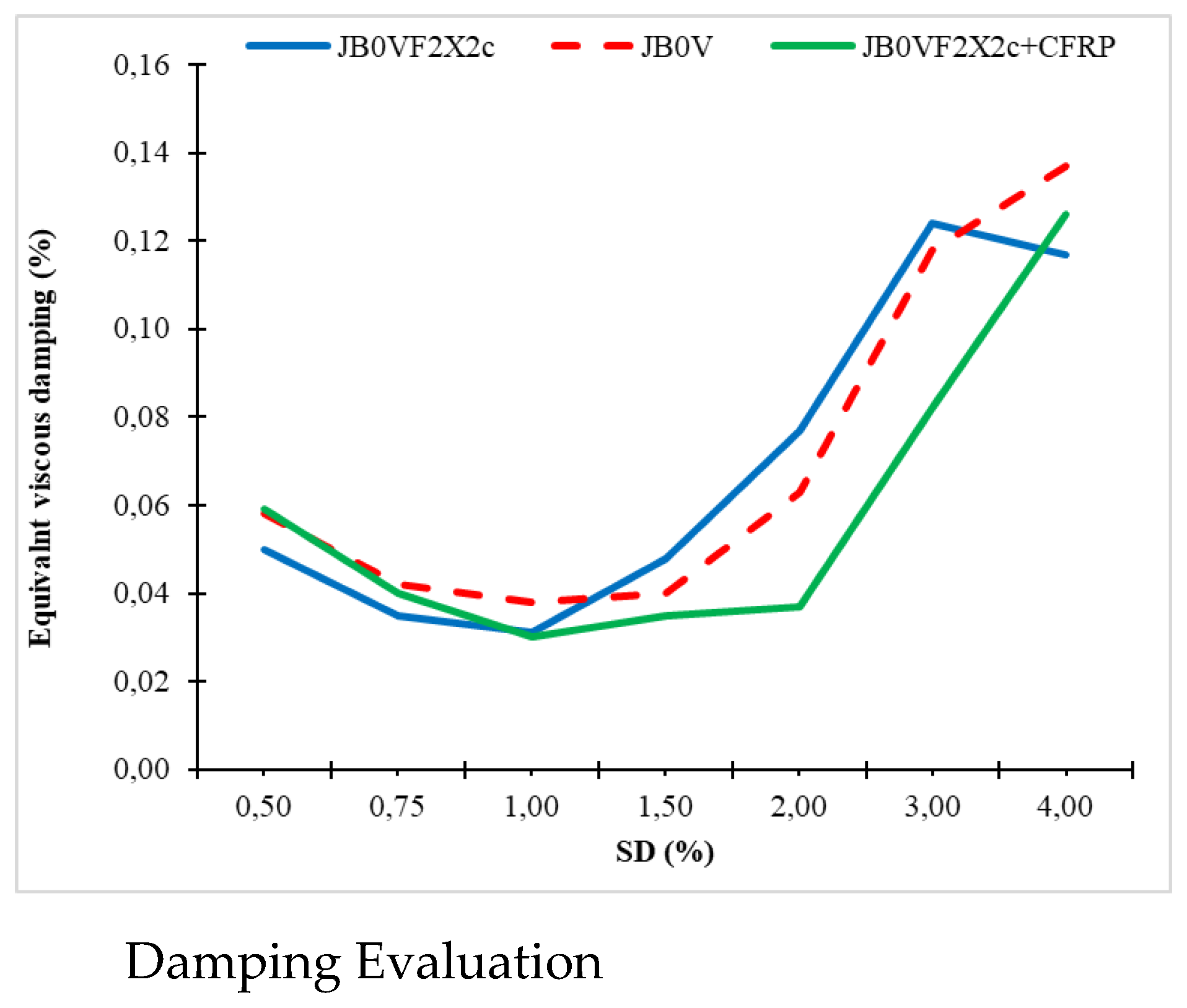
The analysis of the diagram illustrating equivalent viscous damping (%) as a function of the story drift ratio (SD%) reveals the evolving behavior of the specimens in terms of their energy dissipation capacity under cyclic loading [29]. As observed, all specimens exhibit an initial decrease in damping up to approximately 1% SD, followed by a gradual and significant increase at higher deformation levels. This phenomenon is attributed to the transition from elastic to inelastic behavior, with the progressive activation of mechanisms such as cracking, debonding, localized failures, and material friction.
The pilot specimen JB0V shows the highest equivalent damping for SD values greater than 3%, reaching up to 0.15. This is attributed to intense inelastic deformation and the early activation of failure mechanisms compared to the strengthened specimens. JB0VF2X2c, which includes strengthening only at the column, displays slightly lower damping within the same deformation range, maintaining higher stiffness and therefore exhibiting more limited inelasticity.
In contrast, the fully strengthened specimen JB0VF2X2c + C-FRP, which is reinforced both at the column and the beam, presents the lowest damping values up to 2.5% SD. This behavior suggests a delayed activation of inelastic mechanisms due to its increased initial stiffness. However, beyond this threshold, damping rises sharply, reaching levels comparable to those of the other specimens at 4% SD. This indicates the specimen’s ability to sustain elastic behavior over a broader loading range before entering into significant nonlinearity.
In summary, the diagram highlights the differentiated response of the specimens in terms of energy dissipation. JB0V absorbs more energy through uncontrolled damage, whereas JB0VF2X2c + C-FRP achieves high damping at larger deformation levels in a more controlled manner. The use of C-FRP ropes and sheets appears to delay the onset of severe inelastic phenomena, preserving the structural integrity of the section during the early stages of loading an outcome that significantly enhances both the seismic response and the overall resilience of the structure.
5. Concluding Remarks
This study investigated the effectiveness of a novel strengthening technique for reinforced concrete (RC) beam–column joints using externally applied Carbon Fiber Reinforced Polymer (C-FRP) ropes and sheets. Full-scale cyclic loading tests were conducted on three specimens with varying strengthening configurations to assess their mechanical performance, energy dissipation capacity, stiffness retention, and damage progression.
The experimental findings confirm that the use of X-shaped C-FRP ropes as diagonal reinforcement within the joint core significantly enhances shear resistance and delays the onset of severe damage, even under large displacement demands. When the ropes are combined with externally bonded C-FRP sheets applied to the beam, as in the JB0VF2X2c + C-FRP specimen, the structural performance improves further across all metrics—including load-bearing capacity, ductility, and cyclic energy dissipation.
The analysis of hysteretic behavior, dissipated energy, stiffness degradation, damage index, and equivalent viscous damping demonstrates the superior seismic performance of the strengthened specimens, especially the fully retrofitted one. The pilot specimen JB0V exhibited early stiffness loss, reduced strength, and extensive damage in the joint region, while the strengthened specimens retained structural integrity and showed more controlled energy absorption mechanisms.
Furthermore, the use of C-FRP ropes and sheets did not alter the geometry or mass of the structural elements, offering a practical and non-intrusive solution for retrofitting deficient RC joints. The delayed development of inelastic deformation and the effective confinement provided by the strengthening system resulted in improved by over 40% resilience and damage tolerance under cyclic loading.
In conclusion, the proposed technique, involving a combination of externally applied C-FRP ropes and sheets, is a technically effective and easily applicable solution for upgrading existing RC structures, particularly in seismic zones. It ensures enhanced safety margins, extended service life, and improved post-earthquake performance of critical joint regions.
Author Contributions
Conceptualization, C.G.K.; methodology, E.G.; software, G.I.K.; validation, C.G.K.; E.G.; investigation, E.G.; G.I.K.; data curation, E.G.; writing—review and editing, C.G.K.; visualization, G.I.K.; project administration, C.G.K.; funding acquisition, E.G. All authors have read and agreed to the published version of the manuscript.
Funding
The presented research received no external funding.
Data Availability Statement
Data available on request.
Acknowledgments
We would like to thank the company SIKA HELLAS SA for the supply and free disposal of the needed FRP materials.
Conflicts of Interest
The authors declare no conflict of interest.
References
- Bakis, C.E.; Bank, L.C.; Brown, V.L.; Cosenza, E.; Davalos, J.F.; Lesko, J.J.; Triantafillou, T.C. Fiber-reinforced polymer composites for construction—State-of-the-art review. Journal of Composites for Construction 2002, 6, 73–87. [Google Scholar] [CrossRef]
- Antonopoulos, C.P.; Triantafillou, T.C. Experimental investigation of FRP-strengthened RC beam-column joints. Journal of Composites for Construction 2003, 7, 39–49. [Google Scholar] [CrossRef]
- Al-Salloum, Y.A.; Elsanadedy, H.M.; Alsayed, S.H.; Iqbal, R.A. Seismic performance of RC beam–column joints upgraded with FRP sheets. Journal of Composites for Construction 2012, 16, 74–90. [Google Scholar] [CrossRef]
- ACI 440.2R-08; Guide for the Design and Construction of Externally Bonded FRP Systems for Strengthening Concrete Structures. American Concrete Institute: Farmington Hills, MI, USA, 2008.
- Ehsani, M.R.; Saadatmanesh, H.; Tao, S. Design recommendations for flexural strengthening of RC beams with FRP plates. ACI Structural Journal 1993, 90, 34–41. [Google Scholar]
- Bousias, S.N.; Spadea, G.; Triantafillou, T.C. Seismic retrofitting of beam–column joints using carbon-FRP jacketing. ACI Structural Journal 2007, 104, 287–296. [Google Scholar]
- Cosenza, E.; Manfredi, G.; Realfonzo, R. Behavior and modeling of bond of FRP rebars to concrete. Journal of Composites for Construction 1997, 1, 40–51. [Google Scholar] [CrossRef]
- Bencardino, F.; Condello, A.; Spadea, G.; Swamy, R.N. Experimental performance of RC beams strengthened with FRP materials. Composite Structures 2010, 92, 2066–2077. [Google Scholar] [CrossRef]
- El-Amoury, T.; Ghobarah, A. Seismic rehabilitation of beam–column knee joints using GFRP sheets. Engineering Structures 2002, 24, 1397–1407. [Google Scholar] [CrossRef]
- Tsonos, A.G. Effectiveness of CFRP jackets and RC jacketing in post-earthquake and pre-earthquake retrofitting of RC beam–column subassemblages. Engineering Structures 2007, 29, 1216–1232. [Google Scholar]
- ACI Committee 318; Building Code Requirements for Structural Concrete (ACI 318-19). American Concrete Institute: Farmington Hills, MI, USA, 2019.
- Pantelides, C.P.; Volnyy, V.A.; Reaveley, L.D. Performance-Based Design of Precast Concrete Bridge Columns Using Fiber-Reinforced Plastic Jackets. ACI Structural Journal 2008, 105, 478–486. [Google Scholar]
- Bousias, S.N.; Verzeletti, G.; Fardis, M.N.; Pavese, A. Lateral stiffness of RC structures under cyclic displacements. Journal of Structural Engineering 1995, 121, 583–594. [Google Scholar]
- Sezen, H.; Moehle, J.P. Seismic performance of reinforced concrete buildings damaged by the 1999 Kocaeli, Turkey earthquake; Pacific Earthquake Engineering Research Center (PEER): Berkeley, 2000. [Google Scholar]
- Elnashai, A.S.; Izzuddin, B.A. Inelastic dynamic analysis of buildings using localized plasticity model. Journal of Engineering Mechanics 1994, 120, 1831–1856. [Google Scholar]
- ACI Committee 374; Acceptance Criteria for Moment Frames Based on Structural Testing and Commentary (ACI 374.1-05). American Concrete Institute: Farmington Hills, MI, USA, 2005.
- Krawinkler, H. Loading histories for cyclic tests in support of performance assessment of structural components. Earthquake Spectra 1992, 8, 23–43. [Google Scholar]
- Tsonos, A.G. Effectiveness of CFRP jackets and concrete jackets in retrofitting of beam–column subassemblages. Journal of Earthquake Engineering 2008, 12, 653–675. [Google Scholar]
- Tsonos, A.G. Cyclic load behavior of reinforced concrete beam–column subassemblages upgraded with carbon fiber reinforced polymers. Journal of Structural Engineering 2007, 133, 1309–1318. [Google Scholar]
- Bousias, S.N.; Biskinis, D.E.; Fardis, M.N. Deformation capacity of members and joints of RC frames. Journal of Structural Engineering 2004, 130, 1911–1924. [Google Scholar]
- Paulay, T.; Priestley, M.J.N. Seismic Design of Reinforced Concrete and Masonry Buildings; John Wiley & Sons: Hoboken, NJ, USA, 1992. [Google Scholar]
- Golias, M.; Karayannis, C.G. Full-scale Experimental Testing of RC Beam-column Joints Strengthened using CFRP Ropes as External Reinforcement. Engineering Structures 2022, 250, 113305. [Google Scholar] [CrossRef]
- Golias, E.; Zapris, A.G.; Kytinou, V.K.; Kalogeropoulos, G.I.; Chalioris, C.E.; Karayannis, C.G. Effectiveness of the novel Rehabilitation Method of Seismically Damaged RC Joints using C-FRP ropes and Comparison with widely applied Method using C-FRP sheets—Experimental Investigation. Sustainability 2021, 13, 6454. [Google Scholar] [CrossRef]
- Tsionis, G.; Stylianidis, K. Seismic behavior of reinforced concrete joints strengthened with FRP materials. Construction and Building Materials 2007, 21, 855–865. [Google Scholar] [CrossRef]
- Parvin, A.; Granata, P. Investigation of externally bonded FRP composites for retrofit of concrete structures. Journal of Composites for Construction 2000, 4, 145–152. [Google Scholar]
- Prota, A.; Nanni, A.; Manfredi, G. Experimental investigation of FRP-strengthened RC joints. Journal of Composites for Construction 2003, 7, 95–103. [Google Scholar] [CrossRef]
- Mukherjee, A.; Joshi, M. FRPC reinforced concrete beams under direct shear. Construction and Building Materials 2005, 19, 295–301. [Google Scholar] [CrossRef]
- Khalifa, A.; Nanni, A. Rehabilitation of rectangular simply supported RC beams with shear deficiencies using CFRP composites. Construction and Building Materials 2000, 14, 153–162. [Google Scholar] [CrossRef]
- Pantelides, C.P.; Reaveley, L.D.; Volnyy, V.A. Seismic retrofit of reinforced concrete bridge columns with FRP composites. Journal of Composites for Construction 2002, 6, 10–16. [Google Scholar]
- Antonopoulos, C.P.; Triantafillou, T.C. Analysis of FRP-strengthened RC beam–column joints. Journal of Composites for Construction 2002, 6, 41–51. [Google Scholar] [CrossRef]
- Karayannis, C.G.; Sirkelis, G.M. Strengthening and rehabilitation of RC beam–column joints using carbon-FRP jacketing and epoxy resin injection. Earthquake Engineering and Structural Dynamics 2008, 37, 769–790. [Google Scholar] [CrossRef]
Figure 1.
Geometry and steel reinforcement for the specimens (dimensions in mm): (a) JB0V, (b) JB0VF2X2c, (c) JB0VF2X2c + C-FRP
Figure 1.
Geometry and steel reinforcement for the specimens (dimensions in mm): (a) JB0V, (b) JB0VF2X2c, (c) JB0VF2X2c + C-FRP

Figure 2.
Test setup and instrumentation for the measurement of shear deformation of the joint body of the tested specimens.
Figure 2.
Test setup and instrumentation for the measurement of shear deformation of the joint body of the tested specimens.
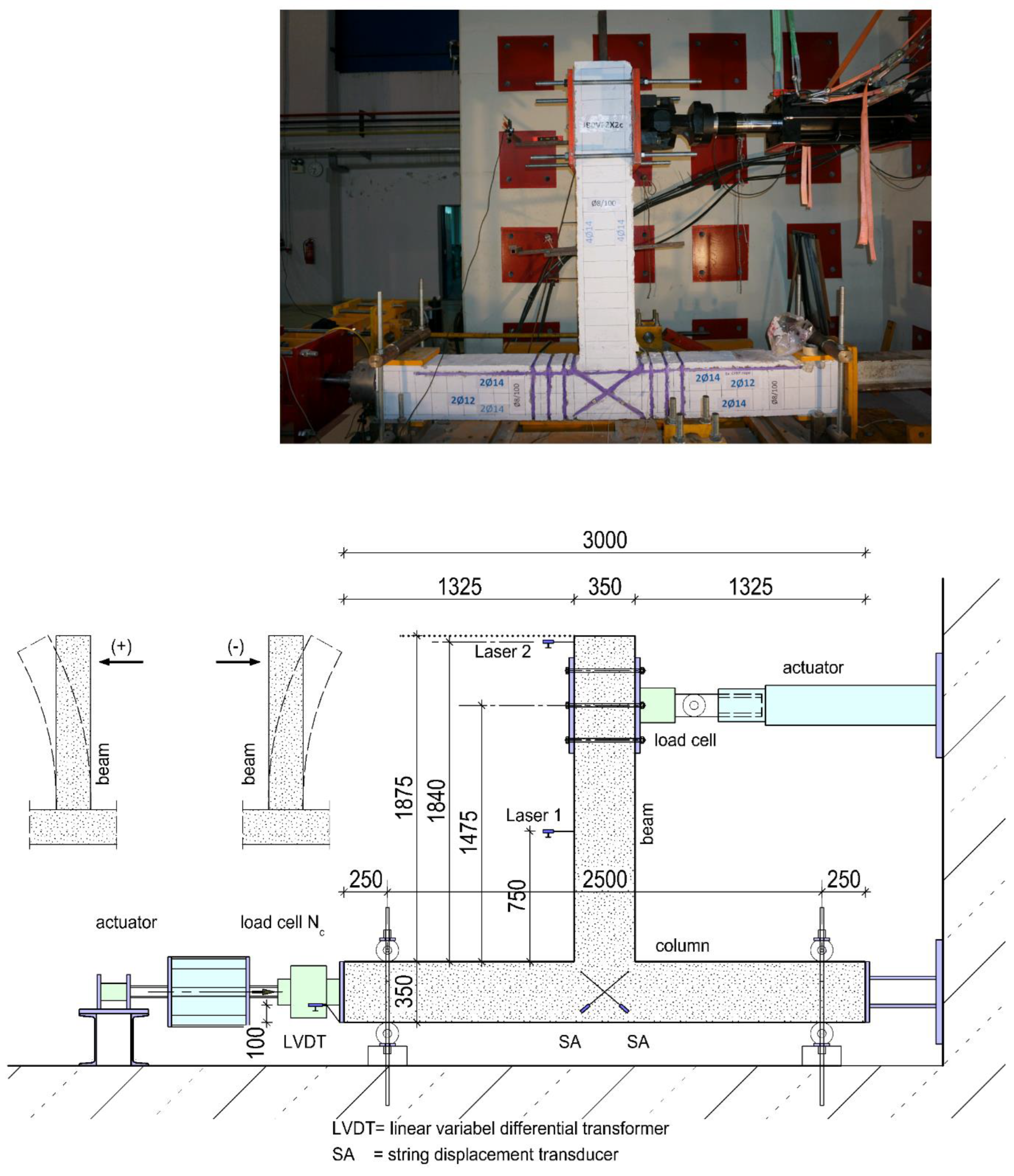
Figure 3.
Loading sequence. Seven loading steps and each step comprises three full loading cycles.
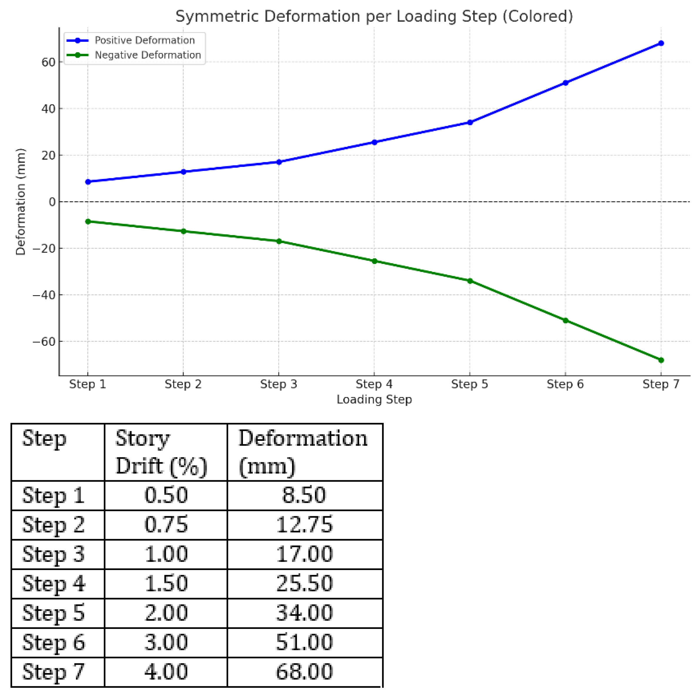
Figure 5.
Final damage mode of the tested beam-column connections.
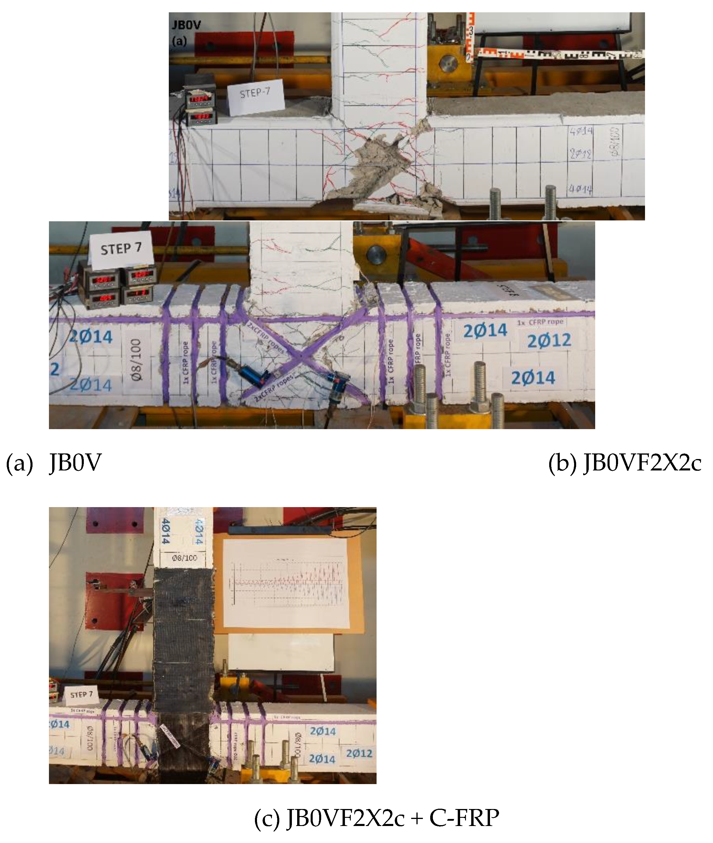

Table 1.
Reinforcements of beam-column specimens.
| Reinforcements | JB0V | JB0VF2X2c | JB0VF2X2c + C-FRP |
|---|---|---|---|
| ➀ | Ø8/100 | Ø8/100 | Ø8/100 |
| ➁ | 2Ø14 | 2Ø14 | 2Ø14 |
| ➂ | 4Ø14 | 4Ø14 | 4Ø14 |
| ➃ | 2Ø12 | 2Ø12 | 2Ø12 |
|
FRP ropes of joint |
- | X-type double C-FRP rope reinforcement | X-type double C-FRP rope reinforcement with C-FRP sheets in the beam |
|
FRP ropes of column |
- | 1x rope at each corner | 1x rope at each corner |
Disclaimer/Publisher’s Note: The statements, opinions and data contained in all publications are solely those of the individual author(s) and contributor(s) and not of MDPI and/or the editor(s). MDPI and/or the editor(s) disclaim responsibility for any injury to people or property resulting from any ideas, methods, instructions or products referred to in the content. |
© 2025 by the authors. Licensee MDPI, Basel, Switzerland. This article is an open access article distributed under the terms and conditions of the Creative Commons Attribution (CC BY) license (http://creativecommons.org/licenses/by/4.0/).
Copyright: This open access article is published under a Creative Commons CC BY 4.0 license, which permit the free download, distribution, and reuse, provided that the author and preprint are cited in any reuse.


