
Submitted:
17 July 2025
Posted:
18 July 2025
You are already at the latest version
Abstract
Hygroelectric materials generate electrical power by harnessing the interaction between ambient water vapor and the surface of the material, exploiting the inherent polarity of water molecules—specifically, the negative and positive charge components on the oxygen and hydrogen atoms, respectively. Hygroelectric devices, also known as humidity electric generators, incorporate molecular structures that function analogously to capacitor plates, producing current upon collision with water molecules. Although the power output of individual devices is modest, stacking lightweight materials in multiple layers can significantly enhance overall performance. In this study, aluminum foil served as the anode, while either copper foil or conductive fabric was employed as the cathode. A gel composed of table salt and sodium alginate was positioned between the electrodes. Various parameters were investigated to optimize power generation, including the incorporation of conductive graphite, thermal treatment (baking), and adjustments to the salt-to-sodium alginate ratio. A 1.2 kg power supply, integrating printed circuit boards and hygroelectric devices, was fabricated and successfully mounted on a 0.5 kg remote control car. This power supply delivered 108 mW at 90% efficiency, enabling the trickle charging of four AA batteries to full capacity over five days. On average, the fabricated hygroelectric devices generated 1.2 ± 0.2 mW over a 14-day period, with a mean output voltage of 55 ± 0.10 V and an average current of 2.1 ± 0.4 A. A higher salt ratio, not baking the devices, and a copper cathode all resulted in significantly higher power outputs. With further optimization of device weight, fabrication parameters, and power output, it is feasible that more energy-intensive applications could be directly supported. Moreover, substantial potential exists for enhancing the base design through the use of advanced materials and novel chemical combinations. Notably, the current devices utilize readily available, minimally processed materials and do not produce toxic waste after use, underscoring their sustainability and practical viability.
Keywords:
hygroelectric materials
; humidity electric generators
; trickle charging
; self-sustaining devices
; renewable energy materials
1. Introduction
1.1. Overview
The growing demand for sustainable and portable energy sources has driven researchers to explore innovative methods of electricity generation, particularly those that can operate in diverse environments and utilize readily available resources. One promising approach is harnessing ambient humidity to generate electricity using low-cost, easily sourced materials [1]. Recent advancements demonstrate that devices constructed from materials such as fabric, sea salt, carbon ink, and water-absorbing gels can efficiently convert atmospheric moisture into electrical energy, with outputs sufficient to power small electronics for extended periods [2,3]. This project aims to develop humidity-driven electric generation devices that are both affordable and lightweight, making them suitable for integration onto a small remote control (RC) car and other small electronics. Low-cost, humidity-powered electricity generators can be effectively fabricated from common materials and mounted on remote control vehicles, providing a sustainable and practical energy solution for mobile, wearable, and environmental sensing applications.
1.2. Background
1.2.1. Prior Work Summary
Hygroelectric materials constitute a novel energy harvesting technology that converts ambient humidity into electrical power through the manipulation of charge-separated water molecules. The fundamental mechanism relies on the natural polarity of water molecules, where oxygen atoms carry negative charges and hydrogen atoms carry positive charges, enabling energy extraction when these molecules interact with engineered polymer surfaces. The structural design of hygroelectric polymers incorporates capacitor-like molecular arrangements that facilitate current generation upon water vapor contact. These materials demonstrate remarkable scalability potential, as lightweight polymer components can be systematically layered and stacked to amplify power output. Laboratory demonstrations have validated this approach, with sophisticated polymer configurations achieving substantial voltage outputs up to 1,000 V through strategic folding techniques [2,4].
The diversity of hygroelectric materials encompasses both naturally occurring and artificially synthesized variants. Biological systems, exemplified by protein nanowires found in Geobacter bacteria, represent evolutionary solutions for humidity-based energy harvesting [1,5,6,7,8]. Complementing these natural systems, engineered alternatives include graphene oxide derivatives, economical paper-graphite hybrid materials, and protein-based cells capable of sustained operation exceeding three months under fluctuating humidity conditions [9,10].
The technological advantages of hygroelectric systems center on their operational independence from solar radiation, making them particularly valuable in consistently humid environments where traditional systems exhibit reduced efficiency [9,10]. Furthermore, the polymer-based composition of these materials presents significant environmental benefits, including recyclability and the elimination of rare earth metal dependencies that characterize conventional solar technologies. This combination of continuous operation capability and environmental compatibility establishes hygroelectric materials as viable supplementary power sources for applications requiring minimal weight penalties.
1.2.2. Limitations of Prior Materials
Hydroelectric materials have long demonstrated the possibility of generating power through atmospheric humidity. However, there have been constant significant challenges when it comes to practically using them. The biggest challenge is the low energy output of the initial devices. Many of these generators are based on graphene oxide and polymers but can only produce nanowatts of power [9,10]. A study on power generation from ambient humidity reported a generated voltage of 0.5V, while others reported voltages of 1.5 V [11,12]. This showcases the relatively low voltage of the units [5]. This means that to use these, we would require a much larger surface area, which is a significant drawback for most applications. In vehicles and electronics, space and weight are critical, and our design's increased power output will be vital for this [9,13,14].
The lifespan and durability of these inventions are another significant issue. Sustained power generation typically lasts for days or hours. This could be for a variety of reasons, such as the polymer structure breaking down. For example, protein nanowires from Geobacter sulfurreducens exhibit voltage outputs for 20 hours before decreasing, but their performance is dependent on a specific humidity gradient [1]. This also presents challenges for the real work, and our prototype, which lasts for months, allows for the adoption of hydroelectric technology. Other devices have variable lifespans, measured from hours to months [3,9,10,15].
Ultimately, many of these materials are highly processed and specialized. This results in issues with economic feasibility. The synthesis of materials such as graphene oxide and protein nanowires is a complex and not scalable process [2,4,5]. This means that the current devices are expensive, and our work can sharply contrast this by introducing cost-effective and readily available materials. This is a crucial step in our mission to enhance hydroelectric technology. These advancements enable reliable power generation in a broader range of real-world.
1.2.3. Issues with Photovoltaics and Other Renewables
Photovoltaic (PV) technologies, while central to the transition toward renewable energy, face significant limitations related to material use, industrial overhead, and end-of-life management. The rapid expansion of PV deployment is projected to generate between 60 and 78 million tons of e-waste by 2050, presenting a substantial environmental challenge due to the presence of hazardous materials such as lead, cadmium, and polymers that release toxic gases if improperly disposed [16,17,18]. The recycling of PV panels and other renewable components is complicated by their composite structure, including adhesives and sealants that hinder disassembly and material recovery. Furthermore, the production of PV panels requires large quantities of processed materials (including high-purity silicon, aluminum, and rare earth metals) which are energy-intensive to extract and refine, contributing to resource depletion and environmental degradation [16,17,18]. Industrial overhead is further amplified by the need for specialized recycling infrastructure, which is often economically unviable given the low volume of end-of-life panels currently available and the high cost of recycling compared to landfill disposal. Additionally, the heterogeneity and impurity of PV materials present technical barriers to efficient recycling at scale, often resulting in the accumulation of waste and the loss of valuable resources [16,17,18]. Without robust regulatory frameworks and advancements in recycling technology, the environmental footprint of PV systems risks undermining their sustainability benefits.
1.2.4. Advantages for Hygroelectric Trickle Chargers
Hygroelectric, or humidity electric generator, devices present several distinct advantages for powering wearable electronics, small robots, and compact electric vehicles (EVs). Foremost, these systems do not require prior infrastructure such as sunlight exposure or mechanical input, as they harvest ubiquitous atmospheric moisture, enabling deployment in diverse environments where other energy sources may be limited or unavailable. Manufacturing costs are inherently low due to the use of abundant, safe, and printable materials (such as biodegradable polymers or edible salts) facilitating scalable and environmentally friendly production processes. In contrast to PV panels, which are subject to significant fluctuations in power output due to diurnal and weather variations, hygroelectric generators can provide a more constant power supply in environments with stable humidity, supporting uninterrupted operation of low-power devices [10]. Furthermore, recent advances demonstrate that hygroelectric generators maintain stable performance over extended periods and under mechanical deformation, underscoring their suitability for integration into flexible, wearable, or mobile platforms [3,9,10,15]. Unlike traditional PV, hygroelectric cells can be physically stacked and layered upon each other without performance loss to energy and power density. These attributes collectively position hygroelectric generators as promising candidates for sustainable, maintenance-free energy solutions in next-generation portable electronics [10]. Even though large EVs require high electrical power relative to conventional renewable energy, small EVs and robots can be useful for transporting small packages [14,19].
2. Materials and Methods
2.1. Overview
A hygroelectric trickle charger was mounted on a small RC car. The scalable model system was suitable for a wide range of applications, including wearable electronics, small robots, remote sensors, and compact electric vehicles. This approach provided a practical test-bed for evaluating energy delivery and system autonomy in devices where size, weight, and continuous operation are critical considerations [14]. To ensure the model is accessible and reproducible without the need for heavy industrial infrastructure, all components and fabrication techniques were selected based on their low cost, safety, and suitability for use in a typical kitchen or home workshop. This methodology aligned with recent trends in the development of wearable and flexible electronics, where affordable, non-toxic, and easily processed materials, such as food products and commercially available components, enabled rapid prototyping and broader adoption.
2.2. Car and Power Supply Requirements
The power supply was designed around a toy car chassis. The RC car used was a model vehicle manufactured by Jada Toys (City of Industry, CA., United States). By default, it was powered by 4 AA batteries in series, generating a total of 6 V in direct current (6 VDC) [20]. While prior work with PV utilized drones, electric aircraft required more power than surface vehicles [19,21,22]. The current load varied, depending on whether standard movement or a “speed burst” was used. For test purposes, only the standard speed was used. The car was capable of carrying 2.7 kg, and it weighed about 0.5 kg in its default configuration. The plastic outer shell could be removed for further speed, but its weight was negligible (143 g). While directly running the car was unlikely, a trickle charging system could be integrated with the batteries. The final device would consist of hygroelectric devices integrated with printed circuit boards (PCBs), which would trickle charge batteries. The power supply would need to maximize voltage and current to increase power [23], while accounting for potential variability and degradation of handmade devices. The system overview is shown in Figure 1.
2.3. Prior Hygroelectric Devices
Prior work was used for initial devices. Polymer films were initially replicated, but proved too fragile and required specialized polymers [21. Asymmetric desiccant devices were fabricated from conductive cloth [27,28,29], but preparation times were too long (~ 8 hours). Laser-induced graphene devices were fabricated, but required specialized equipment in the form of a laser etcher and polyimide sheets. Devices requiring only food additives and metallic foil were fabricated, but internal resistance made scaling difficult [24]. Aspects of these devices were integrated into a streamlined design, which could be produced with copper, aluminum foil, and food additives in a common kitchen. The baking time and temperature was adapted directly from prior work [24]. The fabrication technique was adapted to other materials.
2.4. Initial Device Fabrication
The devices initially fabricated were based on a streamlined procedure from Duan, et al. (2024) [24]. As shown in Figure 2, corrugated cardboard was cut to roughly uniform sizes, and a connected layer of the material was applied to both sides. Double layers enabled devices to be “stacked” in series more efficiently. Aluminum foil was used as the anode, while either copper foil or conductive fabric was used for the cathode. Between both was a solution of table salt and sodium alginate. Both salt and sodium alginate were mixed from 3 g each, combined in a 1:1 ratio and mixed by hand with 10 mL of tap water. The resultant gel mixture was placed between copper and aluminum foil and then pressed together. As with prior work, the “sandwich” devices (with a thickness of 7 mm and mass of 0.25g) were then baked in an oven for 90 min at 77 degrees Celsius [24]. The devices were cooled at room temperature for 10 min, and then measured with a multimeter (AM33D, AstroAI). Due to findings with prior replication, several changes were explored to potentially improve the initial process.
2.5. Variant Device Fabrication
Prior work inspired fabrication procedure changes. As with prior work, conductive carbon greatly reduced internal resistance [25,26]. Unlike in prior work, a more readily available material was used instead of graphene: mechanical pencil “lead,” or conductive graphite. One process variable was the integration of conductive graphite, made by grinding 1 g of conductive graphite powder and place it into the salt and sodium alginate gel. Another noted issue with the initial device was the oxidation and degradation of the copper cathode. As prior work with carbon-based materials did not exhibit the more rapid degradation observed with copper, conductive fabric was explored as an alternative cathode [27,28,29].
The use of conductive fabric was another variant condition. Another experimental condition was adjusting the electrolyte concentration, which was previously reported to increase the ratio of salt to sodium alginate [24]. Increasing the salt to sodium alginate ratio to 3:1 from 1:1 was another experimental condition. Lastly, the need to bake devices was found to potentially be unnecessary, due to accidentally leaving out a batch of unbaked devices that still produced power. Removing the need to bake devices could greatly increase fabrication efficiency by lowering time, resulting in another experimental condition. To ensure reliable readings and account for individual variation, four samples of each device were fabricated.
2.6. Device Measurement
All samples were measured in a uniform, consistent measurement, as with other device performance tracking [3]. Each set of samples was stored in a zipped plastic bag to limit potential exposure to excessive moisture. A common multimeter was used to measure voltage and current for each sample, once per day for 14 days. The average voltage and current for each batch of sample was recorded, separated by cathode type, salt ratio, the presence of graphite, and other experimental parameters. The power P in Watts was calculated using Equation 1, where measured voltage V was multiplied by measured current I in amps [23].
P = V x I
The power per square centimeter was calculated for each day, based on the amount of gel applied and direct contact surface on each electrode. The power density, accounting for the current device thickness, was calculated using Equation 2. The power density pd in cubic centimeters was calculated using the area A in square centimeters, mass m, and thickness t, converted from millimeters [30,31,32].
pd =A*t*m
The average power over time was tracked, to compare any potential effects on longevity. Measurements were conducted at an average relative humidity (RH) of 50%.
2.7. Statistical Analysis
A statistical analysis was performed utilizing mixed model analysis of variance with repeated measures (ANOVA). The effects included cathode type, salt ratio, graphite, and baking. Based on the lack of observed degradation on carbon-based materials relative to copper, it was hypothesized that the graphite would increase longevity. Prior literature reported that asymmetric desiccant profiles did not saturate like symmetric devices did, so it was hypothesized that all materials would degrade over time due to ambient humidity [27]. After ANOVA on Python (Python3, Python Software Foundation, Wilmington, Delaware, United States), post-hoc Tukey tests were conducted.
3. Results
3.1. Overview
The prototype began with PCB design and optimization, and then exploration of device parameters. Two PCBs were designed, one where devices were attached in series and another where devices were attached in parallel. The series board was used to build voltage, and the parallel board was used to maximize current. The output power then passed through a buck converter and diode. After optimizing the PCBs, the device parameters were explored. Across all device parameter combinations, the optimized average power output was 1.2 (± 0.2) mW. At a thickness of 7mm and mass of 14 g, the power density was estimated at 1.7 mW/cm^3. The average voltage was 0.55 (± 0.10) V, and the average current was 2.1 (± 0.4) A. With a conversion efficiency of 90%, the average charge time for 4 batteries was approximately 125 (± 1) hours or 5.2 days.
3.2. Power Supply Details
The power supply utilized PCBs connected with individual hygroelectric devices. The voltage driver board connected hygroelectric devices in series, followed by one that connected hygroelectric devices in parallel to maximize current. The PCBs were wired to the hygroelectric devices with alligator clips and wires. From the PCBs, they could be output to the 4 rechargeable 2500 mAh AA batteries (Duracell, Chicago, IL, United States).
The PCBs were designed to facilitate efficient interconnection of the hygroelectric devices, ensuring proper power scaling. Up to 24 parallel connections were utilized to increase current capacity, while 12 series connections were implemented to achieve the target voltage level, resulting in a total of 288 possible device interconnections (24 × 12). The selection of 12 series connections was determined by the required input voltage; with an average output voltage of 0.55 (± 0.10) V per hygroelectric device, 12 devices in series yielded over 6 V, which served as the input to the PCB. This configuration enabled the system to power 6 V applications directly or to provide a higher voltage input for subsequent step-down conversion.
As shown in Figure 3, the series board was designed to be 40 mm by 100 mm. On either side, the terminal block had 5.08 mm holes. Every other hole is electrically connected for a series connection. These connections were connected with 5.08 mm holes. The PCB contained enough terminal holes for 12 devices to be connected in series, so that ~6V can be read across the top terminal blocks.
The number of parallel connections was determined by the maximum number of devices that could be reliably fabricated and connected. Unused parallel connections did not affect the board’s functionality, but each additional parallel connection increased the current output by approximately 1 mA. Consequently, careful consideration was given to selecting an optimal number of devices to be connected to the PCB, balancing all relevant constraints.
As shown in Figure 4, the board was designed with the same dimension as the series board, 40 mm by 100 mm. Additionally, each of the boards was mounted with a standard screw hole in each of the corners. This allows future frame designs to be explored. The terminal block had 5.08 mm holes on either side. Every terminal block is eclectically connected on either side, creating a positive and negative rail for each series board to be hardwired to.
The final product included 12 devices each connected to a series board, and 24 series boards connected across 2 parallel boards. The system had 288 devices, connected in both series and parallel to create a source of 6V 25 mA under ideal conditions. This number of devices was chosen considering the an estimated of devices that could fit reliably in a cardboard shoe-box (27 cm by 13 cm by 37 cm), as well as the size of the RC car and desired power supply output.
As 1.5V is needed for charging, 4.5V was converted to current. The buck converter performed the conversion at 90% efficiency which will result in the output from the buck converter being 1.5V and 72mA. After passing through the buck converter, the flow entered the 1N914 diode. The 1N914 diode was responsible for ensuring that there was no reverse current during battery charging. The Schottky diode was chosen as this is the most power efficient diode meaning that the maximum amount of safe power will be delivered to the battery [33,34]. After passing through the diode, the battery will then begin to charge. The resulting voltage drop across the diode was accounted for in the overall system design. The power supply, even using the heaviest devices in a cardboard box, ended up being 1.2 kg.
3.3. Device Parameters
The device parameters were monitored over 14 days. Baked and unbaked devices are compared in Figure 5.
The unbaked cloth devices had the highest power output after 2 weeks, at 3 (± 0.5) mW with a 0.6V and 5 mA.
The effects of graphite on devices were compared in Figure 6. The highest power was noted with baked copper with graphite a 2 (± 0.2) mW.
The effects of salt ratio were plotted in Figure 7. The highest performance was noted with baked copper and the max salt ratio (1:3) at 3 (± 0.2) mW.
The average power was plotted for selected parameter combinations in Figure 8. The highest average power over 14 days was observed with unbaked copper at 1.59 ± 0.04 mW. While copper was consistently higher than conductive fabric, physical oxidation and degradation was noted relative to conductive cloth. In certain cases, the alligator clips corroded off the copper devices.
3.4. Statistical Outcomes
The results from ANOVA are shown in Table 1.
Statistically significant differences were observed for five parameters. The first was baking, regardless of all other conditions (p < 0.01). Next was the cathode material, in conjunction with the graphite, baking, and salt ratio separately (p < 0.02).
Finally, the combination of cathode, salt, and baking all made statistically significant changes (p < 0.01).
While significantly higher current readings were consistently recorded, copper cathode devices were visibly degraded. As shown in Figure 9, such degradation was not observed on conductive cloth cathode devices.
4. Discussion
4.1. Overview
The 1.2 kg power supply was successfully mounted on the 0.5 kg RC car, although physically stabilizing it was a challenge at higher speeds. A total of 4 rechargeable AA batteries, each with 2500 mAh, were charged by a system that provided 108 mW at 90% efficiency. The charge time from total depletion was approximately 5.2 days, approximately 125 (± 1) hours. Each device provided an average power across all device types was 1.2 (± 0.2) mW, with an average voltage of 55 (± 0.10) V and average current was 2.1 (± 0.4) A. With a power density estimated at 1.7 mW/cm^3, the device compares favorably to prior literature [25]. Not baking devices resulted in a statistically significant higher average power, where copper was consistently higher than conductive cloth. A higher salt ratio, using 3 g of salt for every 1 g of sodium alginate, also resulted in higher power. A higher salt ratio, not baking the devices, and a copper cathode all resulted in significant differences. The use of graphite was only significant when baking was, suggesting possible thermal effects or the amount included was too small relative to other works [25]. Even if devices do not last beyond 14 days, they could be readily and rapidly replaced at low-cost. However, the current devices require further optimization.
4.2. Limitations
The current approach could have been optimized using other parameters. The 14-day period was shorter than other papers exploring hygroelectric devices. Only two ratios of salt were explored, while prior work explored the topic in far greater detail [24]. The use of graphite might have been too small to have a meaningful reaction [25]. The lack of laser-induced graphene cathodes, among the inclusion of other additives, precluded a direct comparison to prior literature [25]. The lack of an asymmetric dessicant hydrogel prevented an investigation into the long-term viability of such a strategy [27,28,29]. The sample size of 4 devices per parameter combination was a small sample size. Similarly, the use of alligator clips could have acted as an additional source of error, adding large contact resistances or current leaks. The mounted power supply was physically unstable on the RC car, especially at higher speeds. These issues required improvement.
4.3. Future Work
The current devices were sufficient to power a simple RC car, although physical stability of the power supply was an issue. With further optimization of weight and power output, more energy-intensive craft could be powered directly, such as a quadcopter [19]. Mounted rechargers for larger vehicles, from e-scooters to electric cars, could also be explored. The viability of the devices over longer periods, as well as systems for rapid replacement or deployment, would need to be optimized for a commercially or industrially viable system [10]. Improving manufacturing reliability and consistently would be a clear area for further development. Including a moisture gradient hydrogel could improve material endurance [27,29,35]. Reducing, or even removing, the need for conventional batteries and electronics could greatly reduce the weight and complexity of the system. Beyond the scope of the system and manufacturing, materials and chemical combinations could be greatly optimized to improve the base design. Chemical composition could be further explored with simulation prior to experimental implementation. The current devices require very little processed materials beyond common, commercially available ones, which do not leave toxic waste after use.
5. Conclusions
The developed power supply successfully delivered 108 mW at 90% efficiency, enabling the trickle charging of four AA batteries to full capacity over five days. On average, the fabricated hygroelectric devices generated 1.2 ± 0.2 mW over a 14-day period, with a mean output voltage of 55 ± 0.10 V and an average current of 2.1 ± 0.4 A. Notably, unlike photovoltaic (PV) systems, these hygroelectric devices can be directly layered, achieving an estimated power density of 1.7 mW/cm³—comparable to the current state-of-the-art [25]. Various treatments were explored to improve performance, including baking, cathode material selection (copper vs. conductive cloth), adjustment of salt ratios, and the incorporation of graphite to reduce internal resistance. Copper cathodes consistently outperformed conductive cloth, and unbaked devices exhibited the highest average power output. A higher salt ratio, not baking the devices, and a copper cathode all resulted in significant differences, although the results were with a small sample size. With further optimization of device weight and power output, it is feasible that more energy-intensive applications could be supported directly. Additionally, there remains substantial potential for improving the base design through advanced materials and chemical combinations. Importantly, the current devices utilize readily available, minimally processed materials and do not produce toxic waste post-use, highlighting their sustainability and practical viability [16,17,18].
Supplementary Materials
The data, models, and Supplementary Information used in this launcher are available at: https://github.com/javeharron/taal
Author Contributions
Conceptualization, J.L. and Z.S.; methodology, S.M. and Z.S.; software, S.M.; validation, J.L., S.M. and E.S.; formal analysis, J.L.; investigation, S.M.; resources, S.V. and H.A.; data curation, J.L.; writing—original draft preparation, J.L.; writing—review and editing, J.L.; visualization, S.M.; supervision, J.L. and Z.S.; project administration, Z.S.; funding acquisition, J.L. All authors have read and agreed to the published version of the manuscript.
Funding
This research received no external funding.
Data Availability Statement
The data, models, and Supplementary Information used in this launcher are available at: https://github.com/javeharron/taal
Acknowledgments
The authors would like to thank Prof. David Tomasko of The Ohio State University Department of Chemical and Biomolecular Engineering.
Conflicts of Interest
The authors declare no conflicts of interest.
References
- Ren, G., Wang, Z., Zhang, B., Liu, X., Ye, J., Hu, Q. and Zhou, S. (2021) ‘A facile and sustainable hygroelectric generator using whole-cell Geobacter sulfurreducens’, Nano Energy, 89, p. 106361. [CrossRef]
- Wang, H. , Sun, Y., He, T., Huang, Y., Cheng, H., Li, C., Xie, D., Yang, P., Zhang, Y. & Qu, L., 2021. Bilayer of polyelectrolyte films for spontaneous power generation in air up to an integrated 1,000 V output. Nature Nanotechnology, 16(7), pp.811-819.
- Moreira, K.S. , Lermen, D., dos Santos, L.P., Galembeck, F. & Burgo, T.A., 2021. Flexible, low-cost and scalable, nanostructured conductive paper-based, efficient hygroelectric generator. Energy & Environmental Science, 14(1), pp.353-358.
- Wang, H. , Cheng, H., Huang, Y., Yang, C., Wang, D., Li, C. & Qu, L., 2020. Transparent, self-healing, arbitrary tailorable moist-electric film generator. Nano Energy, 67, p.104238.
- Liu, X. , Gao, H., Ward, J.E., Liu, X., Yin, B., Fu, T. & Yao, J., 2020. Power generation from ambient humidity using protein nanowires. Nature, 578(7796), pp.550-554.
- Lovley, D.R. , Ueki, T., Zhang, T., Malvankar, N.S., Shrestha, P.M., Flanagan, K.A. & Nevin, K.P., 2011. Geobacter: The microbe electric’s physiology, ecology, and practical applications. Advances in Microbial Physiology, 59(1), pp.1-100. [CrossRef]
- Kjeldsen, K.U. , Schreiber, L., Thorup, C.A., Boesen, T., Bjerg, J.T., Yang, T. & Schramm, A., 2019. On the evolution and physiology of cable bacteria. Proceedings of the National Academy of Sciences, 116(38), pp.19116-19125.
- Fredrickson, J.K. , Romine, M.F., Beliaev, A.S., Auchtung, J.M., Driscoll, M.E., Gardner, T.S. & Tiedje, J.M., 2008. Towards environmental systems biology of Shewanella. Nature Reviews Microbiology, 6(8), pp.592-603.
- Guan, P. , Zhu, R., Hu, G., Patterson, R., Chen, F., Liu, C., Zhang, S., Feng, Z., Jiang, Y., Wan, T. & Hu, L., 2022. Recent development of moisture-enabled-electric nanogenerators. Small, 18(46), p.2204603.
- Sun, Z. , Wen, X., Wang, L., Ji, D., Qin, X., Yu, J. & Ramakrishna, S., 2022. Emerging design principles, materials, and applications for moisture-enabled electric generation. eScience, 2(1), pp.32-46.
- Huang, Y. , Cheng, H., Yang, C., Zhang, P., Liao, Q., Yao, H., Shi, G. and Qu, L. (2018) ‘Interface-mediated hygroelectric generator with an output voltage approaching 1.5 volts’, Nature Communications, 9(1), p. 4166. [CrossRef]
- Huang, Z., Li, C., Ying, W., Pan, N., Lei, X., Zhang, J., Wang, R. and Wang, J. (2024) ‘A hydrogel-based moist-electric generator with superior energy output and environmental adaptability’, Nano Energy, 126, p. 109673. [CrossRef]
- Goh, C.S. , Kuan, J.R., Yeo, J.H., Teo, B.S. & Danner, A., 2019. A fully solar-powered quadcopter able to achieve controlled flight out of the ground effect. Progress in Photovoltaics: Research and Applications, 27(10), pp.869-878.
- Rodrigues, T.A. , Patrikar, J., Oliveira, N.L., Matthews, H.S., Scherer, S. & Samaras, C., 2022. Drone flight data reveal energy and greenhouse gas emissions savings for very small package delivery. Patterns, 3(8), p.100569.
- Zhu, R., Zhu, Y., Hu, L., Guan, P., Su, D., Zhang, S., Liu, C., Feng, Z., Hu, G., Chen, F. & Wan, T., 2023. Lab free protein-based moisture electric generators with a high electric output. Energy & Environmental Science. [CrossRef]
- Cucchiella, F. , D’Adamo, I., Koh, S.L. & Rosa, P., 2015. Recycling of WEEEs: An economic assessment of present and future e-waste streams. Renewable and Sustainable Energy Reviews, 51(1), pp.263-272.
- Saw, L.H. , Ye, Y. & Tay, A.A., 2016. Integration issues of lithium-ion battery into electric vehicles battery pack. Journal of Cleaner Production, 113(1), pp.1032-1045.
- Gautam, A. , Shankar, R. & Vrat, P., 2022. Managing end-of-life solar photovoltaic e-waste in India: A circular economy approach. Journal of Business Research, 142(1), pp.287-300.
- Goh, C.S. , Kuan, J.R., Yeo, J.H., Teo, B.S. & Danner, A., 2019. A fully solar-powered quadcopter able to achieve controlled flight out of the ground effect. Progress in Photovoltaics: Research and Applications, 27(10), pp.869-878. [CrossRef]
- Walmart (2025) Jada Toys Jurassic World Hollywood Ride Jurassic Park Jeep Wrangler Remote car. Available at: https://www.walmart.com/ip/Jada-Toys-Jurassic-World-Hollywood-Ride-Jurassic-Park-Jeep-Wrangler-Remote-car/645337333 (Accessed: 29 June 2025).
- Roy, S. , Arnold, D., Lin, J., Schmidt, T., Lind, R., Durscher, R., Riherd, M., Houba, T., Anderson, R. & Zito, J., 2011. Demonstration of a wingless electromagnetic air vehicle. University of Florida, Gainesville.
- Xu, H. , He, Y., Strobel, K., Gilmore, C., Kelley, S., Hennick, C., Sebastian, T., Woolston, M., Perreault, D. & Barrett, S., 2018. Flight of an aeroplane with solid-state propulsion. Nature, 563(7732), pp.532-535.
- Ashari, M.I. & Faisol, A., 2020. The analysis of voltage optimization system with parallel series arranger in solar cell. JEEMECS, 3(2), pp.179-186.
- Duan, Z. , Zhang, B., Zhang, M., Yuan, Z., Jiang, Y. and Tai, H., 2024. High-performance electrochemical power generation humidity sensor based on NaCl/sodium alginate humidity sensing electrolyte and Cu/Zn electrodes for visual humidity indication and respiratory patterns detection. Sensors and Actuators B: Chemical, 409, p.135585.
- Yang, S. , Zhang, L., Mao, J., Guo, J., Chai, Y., Hao, J., Chen, W. and Tao, X., 2024. Green moisture-electric generator based on supramolecular hydrogel with tens of milliamp electricity toward practical applications. Nature communications, 15(1), p.3329.
- Ye, R. , James, D.K. and Tour, J.M. (2019) ‘Laser-Induced Graphene: From Discovery to Translation’, Advanced Materials, 31(1), p. 1803621. [CrossRef]
- Zhang, Y. , Guo, S., Yu, Z.G., Qu, H., Sun, W., Yang, J., Suresh, L., Zhang, X., Koh, J.J. and Tan, S.C., 2022. An asymmetric hygroscopic structure for moisture-driven hygro-ionic electricity generation and storage. Advanced Materials, 34(21), p.2201228.
- Xu, T. , Ding, X., Huang, Y., Shao, C., Song, L., Gao, X., Zhang, Z. and Qu, L. (2019) ‘An efficient polymer moist-electric generator’, Energy & Environmental Science, 12(3), pp. 972–978.
- Xu, C. , Fu, C., Jiang, Z., Yang, T. and Xin, M. (2023) ‘Hygroelectric Generator Based on Antisymmetric Modification of Graphene Spheres with Ionic Hydrogels’, ACS Applied Nano Materials, 6(7), pp. 5930–5938. [CrossRef]
- Augustyn, A., 2023. Density. [online] Available at: https://www.britannica.com/science/density [Accessed 29 January 2023].
- BYJU’S, 2023. Volume formulas. [online] Available at: https://byjus.com/volume-formulas/ [Accessed 29 January 2023].
- Jenkins, H. D. B., & Glasser, L. (2003). Standard absolute entropy, values from volume or density. 1. inorganic materials. Inorganic Chemistry, 42(26), 8702-8708.
- Al-Ahmadi, N. A. (2020). Metal oxide semiconductor-based Schottky diodes: a review of recent advances. Materials Research Express, 7(3), 032001.
- American Hakko Products, Inc., 2025. Components 101. [online] Available at: https://components101.com/sites/default/files/component_datasheet/TP5000-Datasheet.pdf [Accessed 29 January 2023].
- Graeber, G. , Díaz-Marín, C.D., Gaugler, L.C. and El Fil, B. (2024) ‘Intrinsic Water Transport in Moisture-Capturing Hydrogels’, Nano Letters, 24(13), pp. 3858–3865.
Figure 1.
Top-level schematic of trickle charging system.
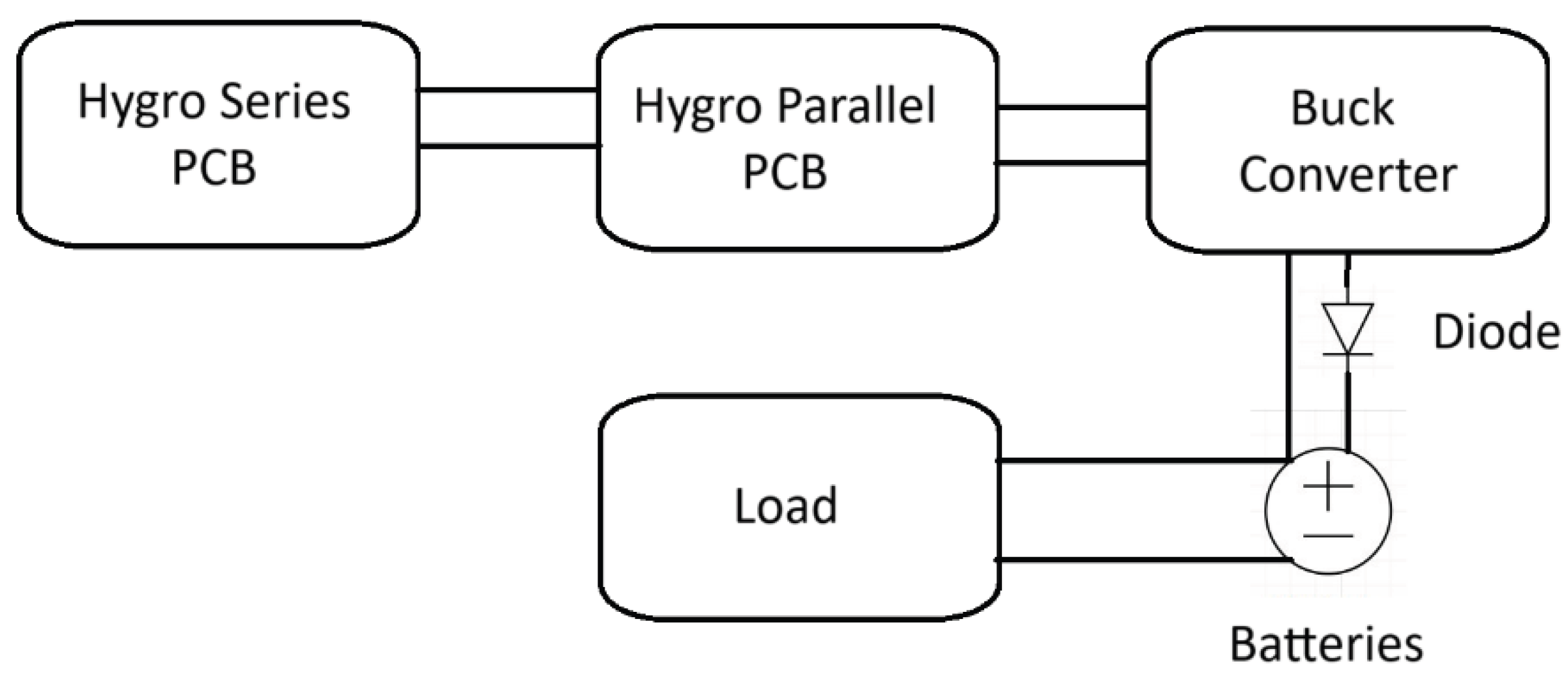
Figure 2.
Electrode materials used (clockwise from top left): Conductive cloth, aluminum foil, and copper foil.
Figure 2.
Electrode materials used (clockwise from top left): Conductive cloth, aluminum foil, and copper foil.
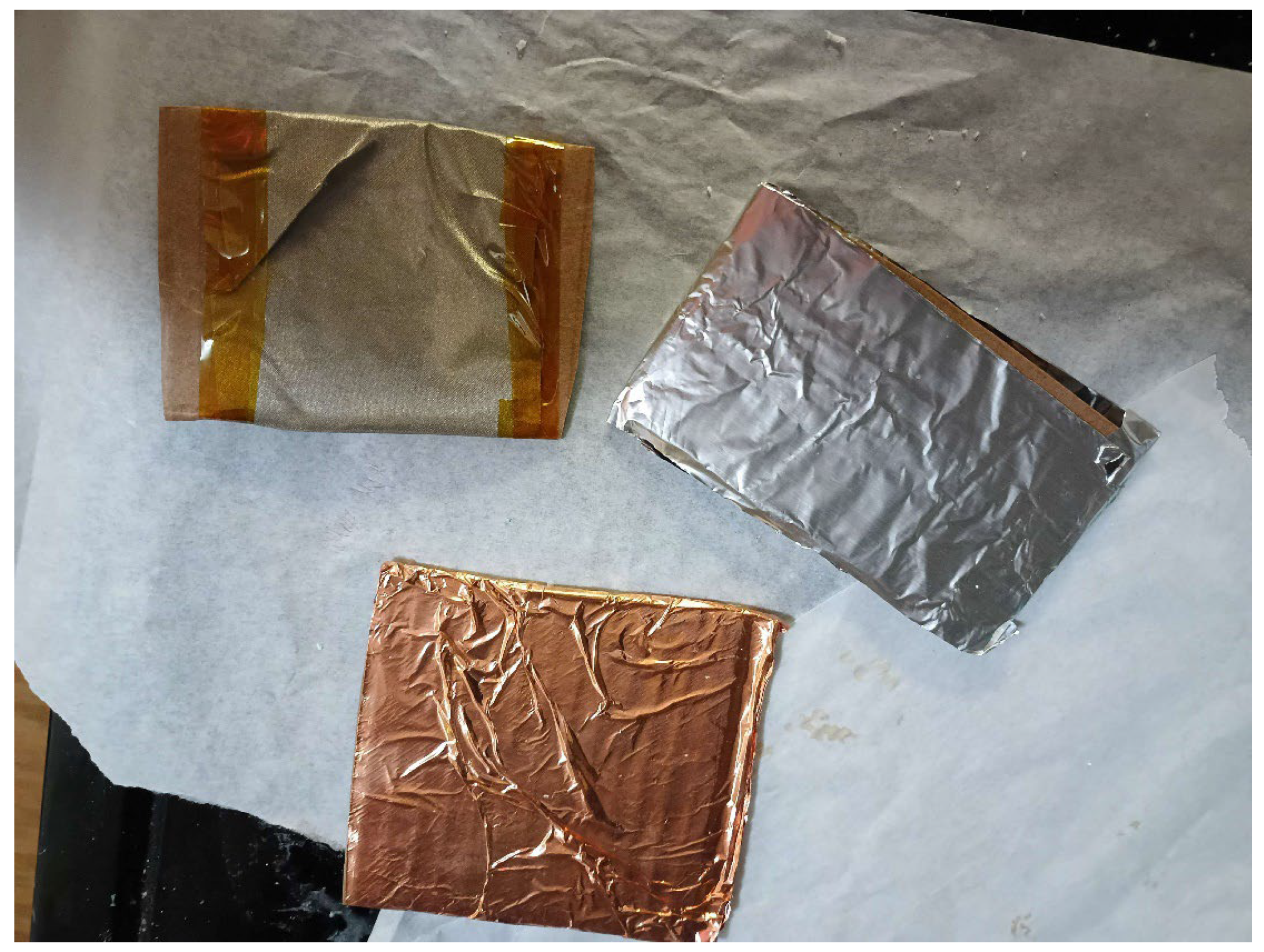
Figure 3.
Diagram detailing the series PCB design.
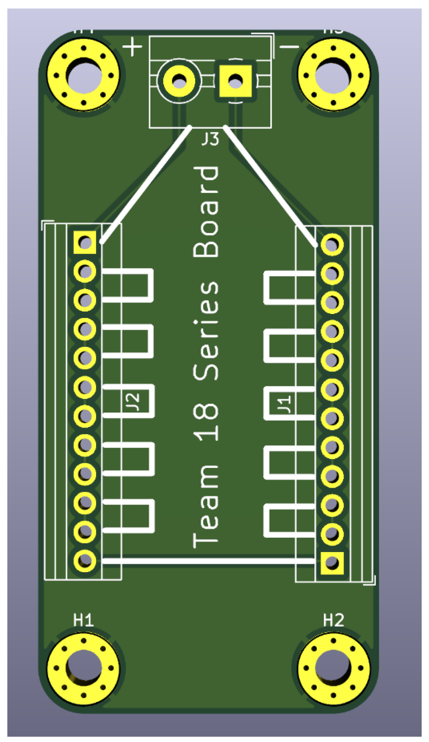
Figure 4.
Diagram detailing the parallel PCB design.
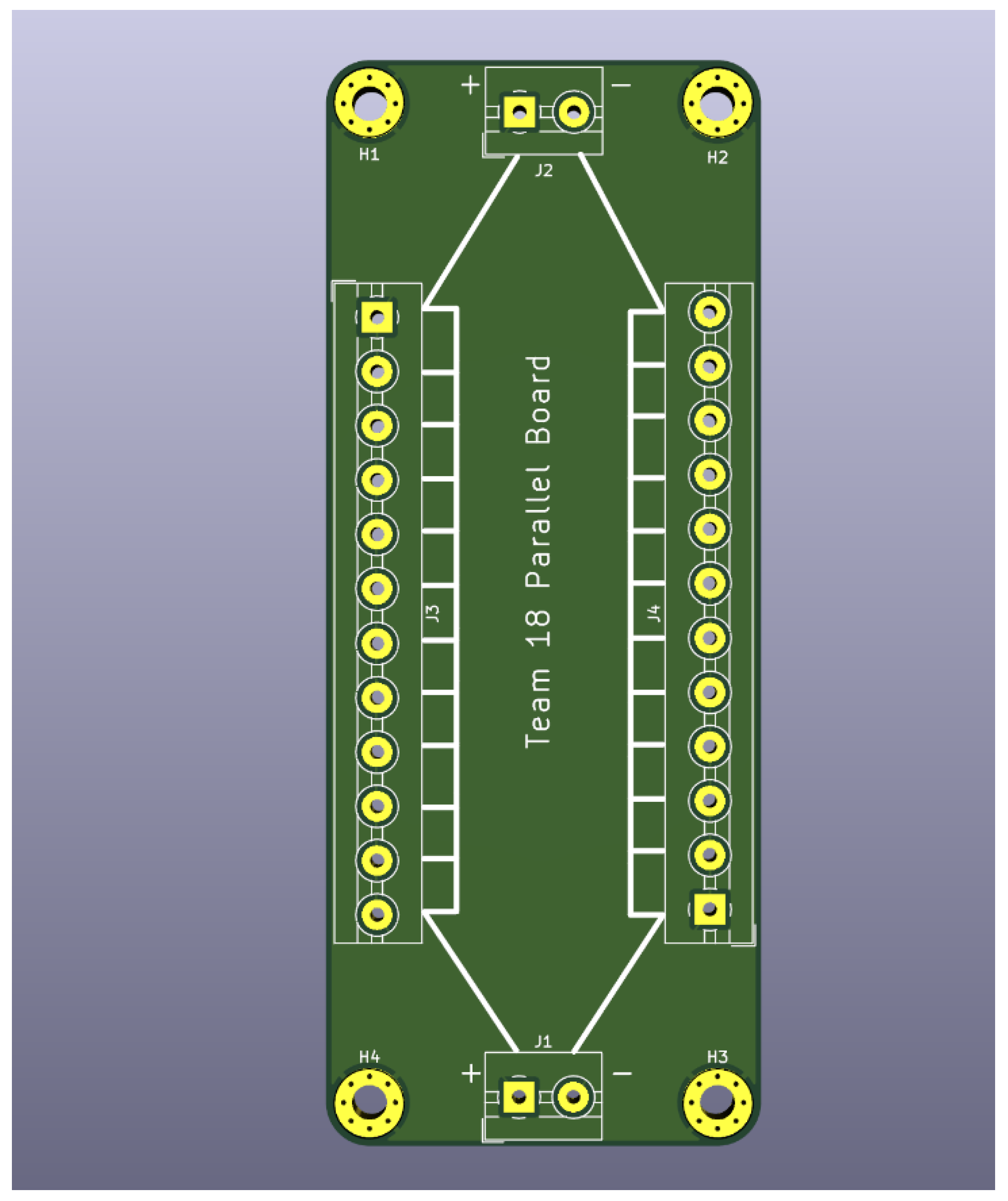
Figure 5.
Performance of baked and unbaked devices over 14 days.
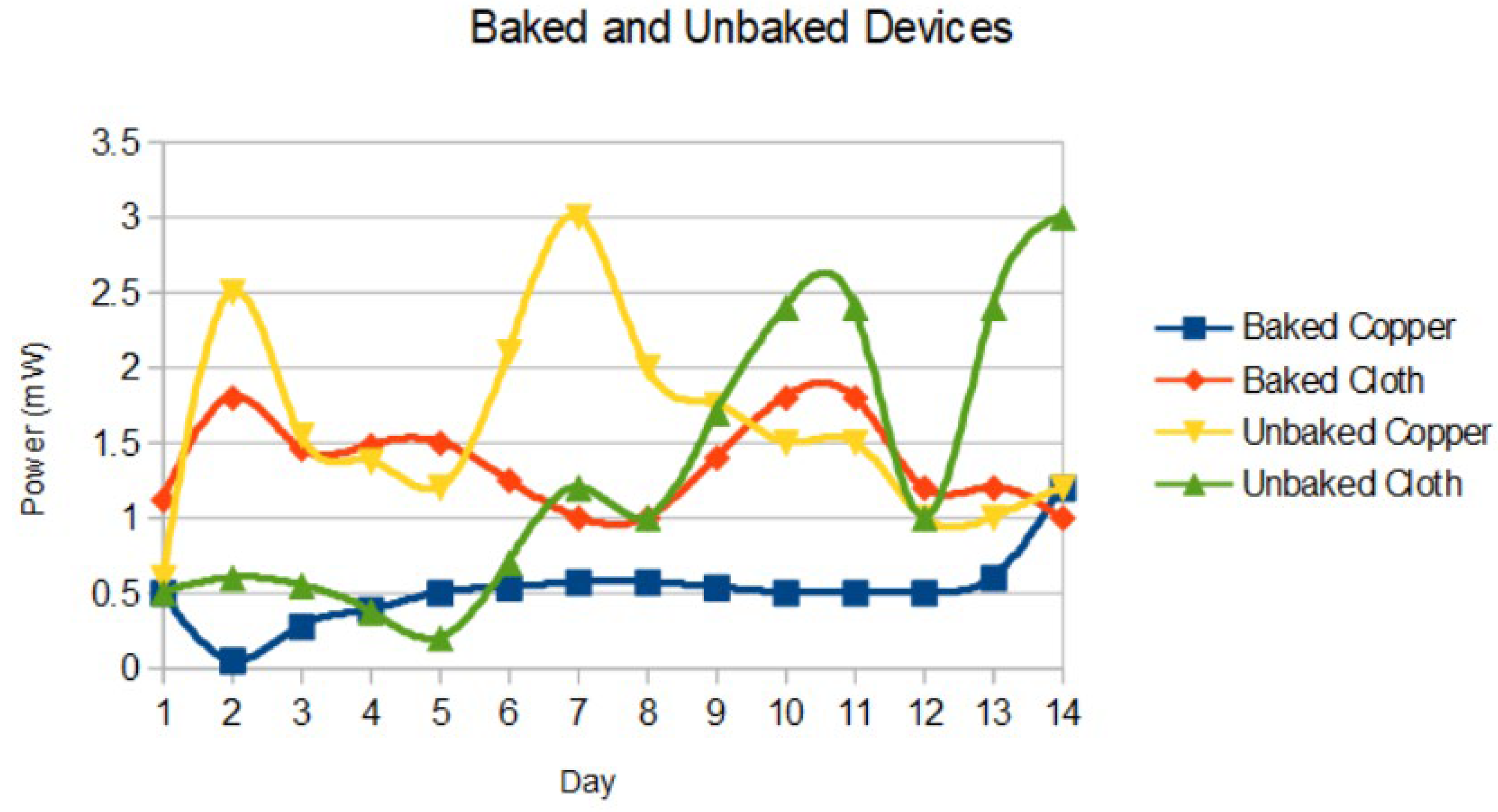
Figure 6.
Performance of graphite and lack of graphite over 14 days.
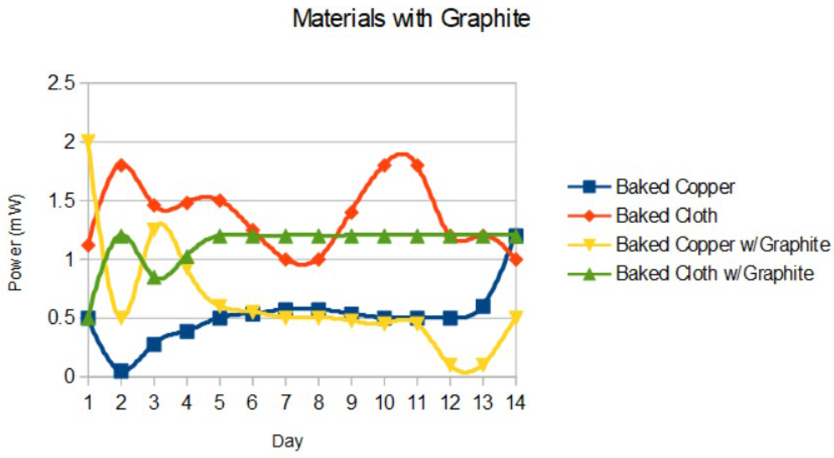
Figure 7.
Performance of standard (1:1) and max (1:3) salt ratios over 14 days.
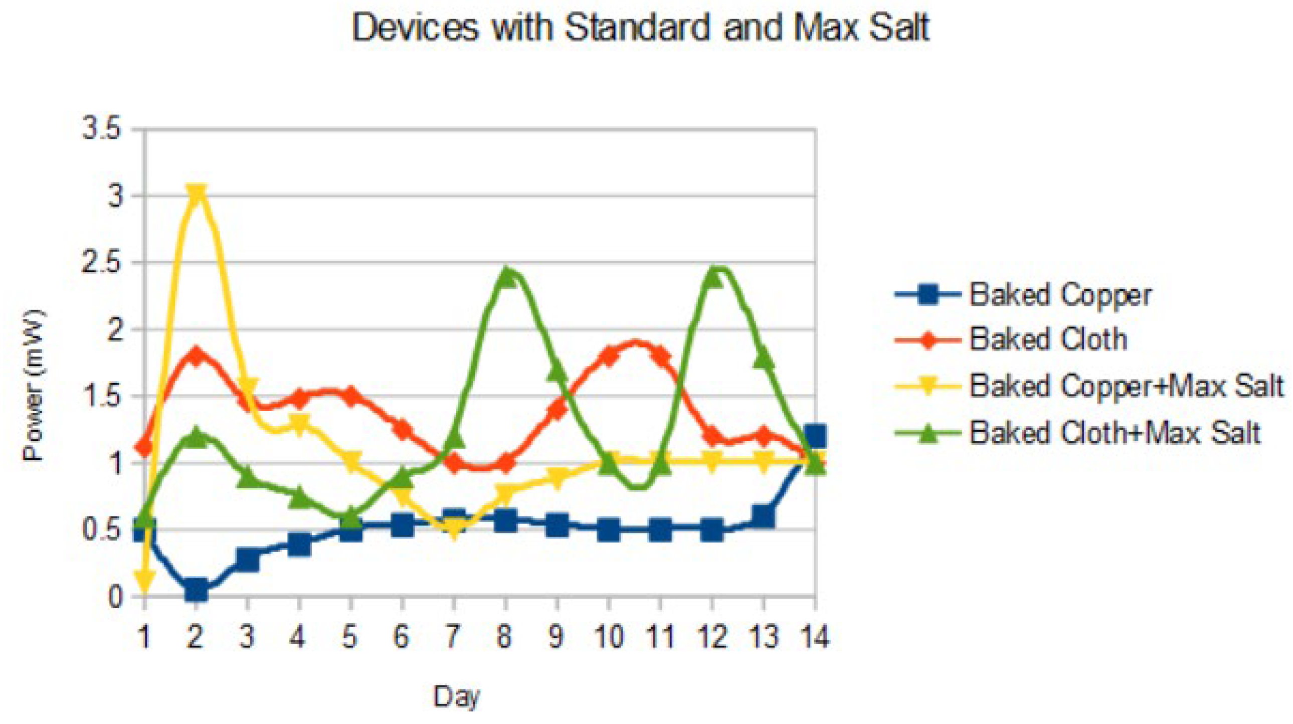
Figure 8.
Comparative average power of different material combinations from 14 days.
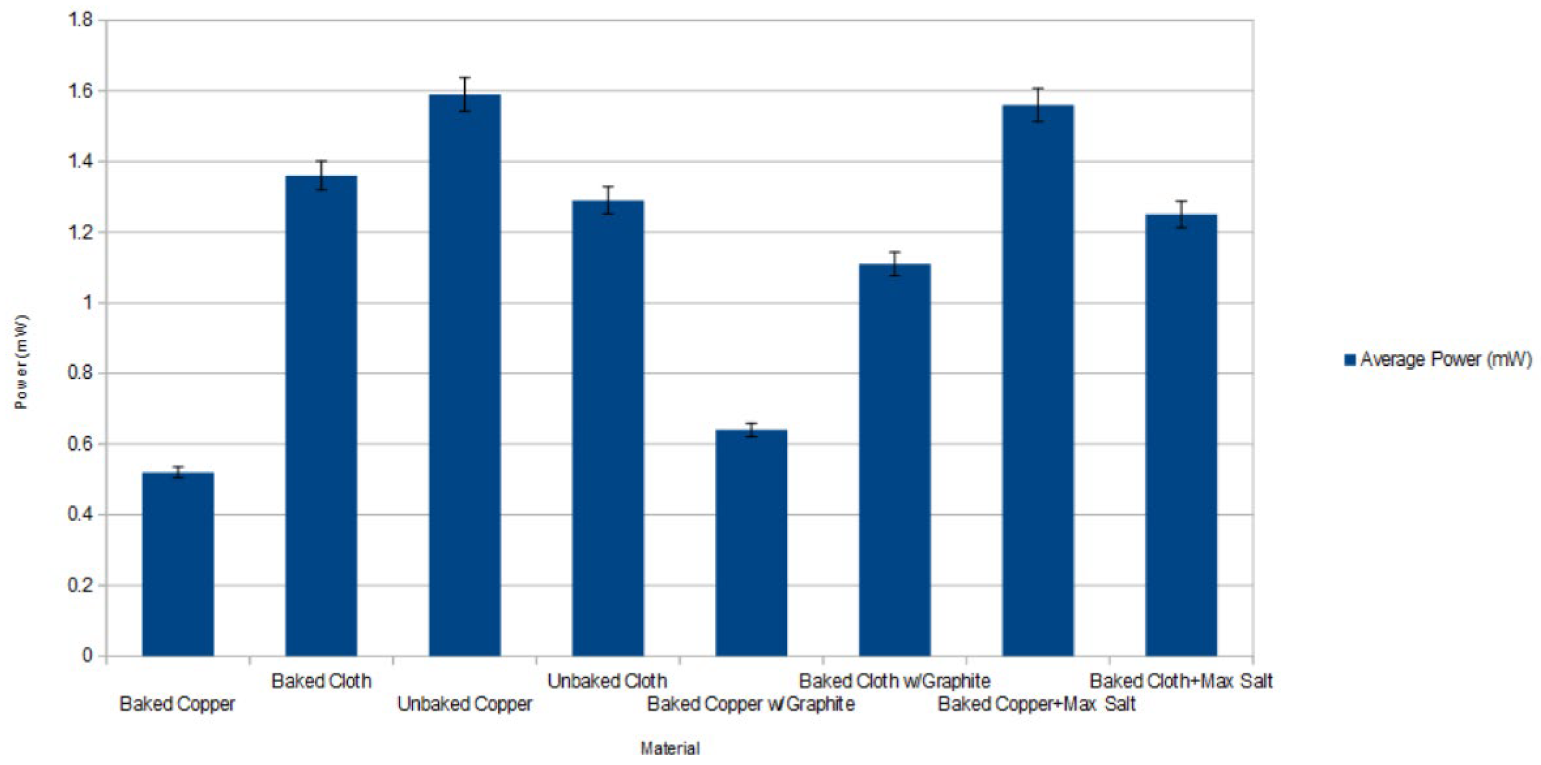
Figure 9.
Direct comparison of copper cathode degradation (top) relative to cloth cathode (bottom).

Table 1.
ANOVA results for investigated parameters.
| Factor | sum_sq | df | F | PR(>F) |
|---|---|---|---|---|
| C(Cathode) | 0.03 | 1.00 | 0.08 | 0.78 |
| C(Graphite) | 0.19 | 1.00 | 0.56 | 0.46 |
| C(Salt) | 0.63 | 1.00 | 1.89 | 0.17 |
| C(Baked) | 3.67 | 1.00 | 10.99 | 0.00 |
| C(Cathode):C(Graphite) | 2.01 | 1.00 | 6.02 | 0.01 |
| C(Cathode):C(Salt) | 2.64 | 1.00 | 7.91 | 0.01 |
| C(Graphite):C(Salt) | 0.28 | 1.00 | 0.84 | 0.36 |
| C(Cathode):C(Baked) | 3.15 | 1.00 | 9.43 | 0.00 |
| C(Graphite):C(Baked) | 0.25 | 1.00 | 0.76 | 0.38 |
| C(Salt):C(Baked) | 1.83 | 1.00 | 5.50 | 0.02 |
| C(Cathode):C(Graphite):C(Salt) | 0.75 | 1.00 | 2.24 | 0.14 |
| C(Cathode):C(Graphite):C(Baked) | 0.69 | 1.00 | 2.07 | 0.15 |
Disclaimer/Publisher’s Note: The statements, opinions and data contained in all publications are solely those of the individual author(s) and contributor(s) and not of MDPI and/or the editor(s). MDPI and/or the editor(s) disclaim responsibility for any injury to people or property resulting from any ideas, methods, instructions or products referred to in the content. |
© 2025 by the authors. Licensee MDPI, Basel, Switzerland. This article is an open access article distributed under the terms and conditions of the Creative Commons Attribution (CC BY) license (http://creativecommons.org/licenses/by/4.0/).
Copyright: This open access article is published under a Creative Commons CC BY 4.0 license, which permit the free download, distribution, and reuse, provided that the author and preprint are cited in any reuse.


