
Submitted:
29 August 2025
Posted:
01 September 2025
You are already at the latest version
Abstract
In this study, we investigated a shielded capacitive power transmission (S-CPT) architecture that utilizes cast iron covers for roads as transmitting electrodes for charging electric vehicles in motion. We evaluated the coupling capacitance in S-parameters for common electrode materials such as copper, aluminum, ductile cast iron, structural steel, and carbon steel. The surface conditions of ductile cast iron electrodes (casting state, machining, and electrocoating) were also compared. Using a four-plate S-CPT operating at 13.56 MHz, the coupling capacitance gap dependence was characterized. Regardless of the material, the coupling capacitance decreases with increasing electrode separation. However, ductile cast iron reached approximately 70 pF at d = 2 mm, demonstrating a high capacitance comparable to copper and aluminum despite its high permeability and resistivity. This indicates that magnetic properties have a limited influence on the coupling characteristics of the S-CPT system. A prototype incorporating a φ330 mm cast iron cover meeting road load and durability requirements was experimentally verified. The system achieved a 58% power transfer efficiency at 100 W input, maintained 40% efficiency at outputs exceeding 200 W, and maintained 45% efficiency even under 200 mm lateral displacement, demonstrating practical robustness under dynamic operation. Simulations confirmed that the shield electrodes provide a large effective grounding capacity, reduce the impedance of the return path, and contribute to the stabilization of the shield potential. Finite element structural analysis confirmed that the ductile cast iron electrodes can withstand a design load of 25 tons as a structural component, ensuring durability. It was demonstrated that the infrastructure can be used without compromising mechanical safety. The proposed infrastructure concept combines the existing cast iron covers of the vehicle with thin aluminum power receiving plates under the vehicle body, eliminating the need for new large coils and reducing installation costs. Overall, the combination of cast iron structural infrastructure and shielded CPT architecture achieves measured high efficiency (58% at 100 W), robust positional tolerance (45% at 200 mm), EMI reduction, and verified mechanical load-bearing capacity (25 tons), paving the way for a cost-competitive wireless charging system in urban areas.
Keywords:
Wireless power transfer
; Capacitive power transfer
; Dynamic wireless charging
; Electric vehicle charging
; Cast-iron electrodes
1. Introduction
In recent years, the electrification of the automotive sector has been accelerating globally in pursuit of a carbon-neutral society. Electric vehicles (EVs), which emit no exhaust gases during operation, are recognized as a key means of reducing CO₂ emissions in the road transport sector and have been highlighted for their role in multiple international reports and research reviews [1]. According to a report by the International Energy Agency (IEA), global EV sales are expected to reach approximately 14 million units in 2023 and increase to 17 million units in 2024. This widespread adoption is projected to reduce oil demand by the equivalent of 6 million barrels per day by 2030, and when combined with decarbonization of the power generation sector, it is estimated that greenhouse gas emissions from the transportation sector can be significantly reduced [2]. In addition, policies such as bans on new sales of fossil fuel vehicles and zero-emission vehicle (ZEV) regulations, which involve phased eliminations, are progressing in various countries and regions, driving the growth of the EV market [3]. In Norway, thanks to large-scale tax incentives and infrastructure development by the government, approximately 90% of new vehicle sales are expected to be EVs by 2024, with steady progress in reducing emissions in the road transportation sector [4]. Furthermore, a spatial quantitative model analysis of 50 cities in China has shown that the spread of EVs will have CO₂ emission reduction effects not only within cities but also in surrounding areas. This study points out that the decarbonization effects of EVs appear through three channels: the replacement effect of internal combustion engine vehicles (ICEVs), the electricity consumption effect, and the technological innovation effect, and that these effects will be further amplified in conjunction with an increase in the share of renewable energy [5].
On the other hand, significant challenges remain in achieving widespread adoption of EVs, including long charging times, limited driving range, and the high costs of developing and maintaining charging infrastructure [6,7,8]. For example, international reviews have repeatedly identified range anxiety and long charging wait times as major factors deterring EV purchases [6]. Additionally, a survey by S&P Global Mobility indicates that charging time and insufficient charging networks are identified as important barriers on par with price, with many consumers seeking short refueling times comparable to gasoline vehicles [7]. Furthermore, according to an analysis by NREL, the installation of charging infrastructure is significantly influenced by soft costs such as permits and construction coordination in addition to hard costs, which are reported to be factors contributing to the high costs of infrastructure development and maintenance burdens [8].
Currently, as a promising technology to address these challenges, Dynamic Wireless Power Transfer (DWPT), which enables contactless power supply during vehicle operation, is gaining attention.
Bi et al. comprehensively organized the fundamentals and applications of wireless power transfer technology for EVs, highlighting technical trends such as compensation circuit design, phase control, and coil layout optimization aimed at improving efficiency [9] . In response, Frontiers in Energy Research conducted a comprehensive review of DWPT, analyzing various aspects such as road-embedded coil design, power electronic circuits, electromagnetic interference (EMI), safety, economic feasibility, and integration with smart grids and renewable energy sources [10]. In practical terms, Sun et al. proposed a new method using RFID technology to achieve high-precision alignment between vehicles in motion and roadside power transmission coils, demonstrating a significant improvement in power transfer efficiency with positional errors of less than 10 cm [11]. Furthermore, Ghassemi et al. analyzed the optimal infrastructure layout considering cost and reliability for large-scale deployment of DWPT systems using a mixed-integer optimization model. This provides guidelines for efficient infrastructure planning across an entire city [12]. Meanwhile, Wang & Nguyen evaluated the voltage profiles and long-term stability of DWPT roads on regional power grids, providing important insights for sustainable implementation considering interactions with power systems [13]. Additionally, Ma et al. organized communication technologies, standardization, and security challenges for both DWPT and SWPT systems, and conducted a detailed examination of data interoperability between EVs and infrastructure, as well as international standardization trends [14].
DWPT is a technology that continuously supplies power to vehicles in motion through a charging system embedded in road infrastructure, thereby reducing charging stop times and contributing to the miniaturization of onboard batteries and the efficiency of autonomous driving.
The objective of this study is to construct a low-cost charging system for road infrastructure toward the social implementation of DWPT (Dynamic Wireless Power Transfer), including SWPT (Stationary Wireless Power Transfer).
Currently, wireless power transfer (WPT) is broadly categorized into two types: magnetic coupling (IPT: Inductive Power Transfer) and electric field coupling (CPT: Capacitive Power Transfer) [15]. The IPT method has been most widely adopted in the market, with international standardization progressing, including the SAE J2954 standard [16]. While IPT offers the advantage of high-efficiency power transmission [17], it faces the following technical challenges. Resource constraints: Copper, used in transmitter and receiver coils, has limited reserves, raising concerns about future resource shortages [18]. Material costs: Magnetic materials such as ferrite, used for magnetic field concentration and leakage suppression, are expensive and contribute to increased system costs [19]. Weight and constructability: Magnetic materials have high specific gravity, increasing weight and thereby increasing installation and maintenance workloads and costs [20]. Furthermore, when power transmission coils are buried in the road surface, there are many structural constraints on the road, significantly limiting construction freedom [21,22]. Safety: There is a risk of foreign objects being heated by leakage magnetic fields, with reports of metal fragments on roads reaching temperatures of over 200°C [23,24]. Therefore, FOD (Foreign Object Detection) and leakage magnetic field countermeasures are essential, leading to system complexity [25].
In contrast, the electric field coupling method (CPT) has recently gained renewed attention due to its lightweight, low-cost, and simple structure [26,27,28]. CPT transmits power using the high-frequency electric field formed between opposing power transmission electrodes and power reception electrodes, and inexpensive aluminum plates or steel plates can be used for the power transmission and reception electrodes [29].
Additionally, it has been reported that CPT is robust against positional misalignment (lateral displacement) and suitable for in-motion power supply due to its ability to ensure a large electrode area [30]. In Japan, a demonstration of a 10 kW-class CPT-type in-motion power supply road was conducted by Taisei Corporation, where an electric field coupling system was embedded within the pavement, achieving an average transmission efficiency of approximately 60% at a speed of 20 km/h [31].
In this study, special asphalt and drainage structures were introduced to suppress dielectric constant fluctuations caused by moisture intrusion into the pavement, and phase-shifting capacitors were installed at 2-meter intervals within the road to prevent localized efficiency losses caused by standing waves.
On the other hand, the construction cost of installing new power transmission electrodes on a large scale is cited as a challenge for CPT implementation in urban areas [32]. In order to promote the widespread use of WPT as road infrastructure, new technologies that combine structural flexibility and transmission characteristics to reduce overall costs, including construction costs, are required.
This study focuses on the possibility of converting cast iron cover structures [33,34,35,36], which are widely used in existing road infrastructure, into electrodes for WPT. Cast iron has high durability and load-bearing capacity [37], but its high electrical resistance leads to iron loss and heat generation issues, making it unsuitable for WPT applications to date [38]. However, in the CPT method, eddy current losses and magnetic flux saturation effects are minimal [27,29], so it is considered feasible to apply cast iron materials with appropriate structural design. Additionally, since electromagnetic interference (EMI) caused by electric field radiation is a challenge in the CPT method, electromagnetic shielding measures will also be considered.
This study aims to propose new materials and structures that leverage the characteristics of the CPT method while utilizing existing road components to construct a low-cost, high-durability in-motion power supply infrastructure, and to evaluate their electromagnetic and structural performance.
The structure of this paper is as follows. Chapter 2 provides an overview of the basic principles of shielded capacitive power transfer (S-CPT), the characteristics of the four-plate configuration, and key design considerations. Chapter 3 presents experimental results obtained using a vector network analyzer (VNA) to compare and evaluate the coupling capacitance of different electrode materials. Additionally, considering the implementation of cast iron electrodes, the influence of surface properties such as corrosion-resistant coating and surface roughness on electric field coupling characteristics is investigated. In Chapter 4, we fabricate a mockup using a φ330 mm cast iron cover that satisfies the load-bearing performance required for installation on roadways, and experimentally evaluate the impedance matching characteristics, power transmission efficiency, and resistance to lateral misalignment. In Chapter 5, we summarize the results of this study and discuss future challenges and directions for development.
2. S-CPT (Shielded Capacitive Power Transfer)
2.1. S-CPT (Shilded Capacitive Power Transfer)
Shielded Capacitive Power Transfer (S-CPT) is a wireless power transfer method that utilizes electric field coupling, enabling high efficiency while suppressing electric field leakage to the outside. As a result, numerous studies have been reported in recent years [39,40,41]. Mahram et al. systematically analyzed the relationship between the gap between the shielded electrode and the power transmission/reception electrodes, the electrode-to-electrode gap, electrode size, and supply power for mini electric vehicles. They proposed a design method combining finite element analysis of coupling capacitance and impedance matching analysis. As a result, simulation showed that a maximum transmission efficiency of 97% is achievable under conditions where the electrode-to-electrode gap is 30 mm [40]. Furthermore, Ahmad et al [41] tested an asymmetric 4-plate configuration S-CPT system at 6.78 MHz and 10 W, achieving an AC–AC efficiency of 84% and successfully reducing potential fluctuations in the shield electrode by 56% through the introduction of a balancing circuit. These results demonstrate the effectiveness of the 4-plate configuration S-CPT and the validity of the design guidelines. Furthermore, in their latest review [42], Zhang et al. summarize the development of CPT technology and challenges for its application to DWPT, emphasizing the importance of high output, high efficiency, and shielding technology. S-CPT is a promising configuration that meets these requirements, and its compatibility with existing infrastructure and flexibility in material selection are also cited as advantages for EV charging infrastructure.
The 4-plate S-CPT studied in this research is designed to suppress electric field leakage by arranging shield electrodes outside the power transmission and reception electrodes, thereby enhancing EMI compatibility. Since it does not utilize magnetic resonance, it does not require expensive and heavy components such as ferrite, and inexpensive sheet materials such as aluminum, cast iron, and steel plates can be used as electrodes, offering high flexibility in material and shape design. As a result, this configuration is expected to simplify the manufacturing process, reduce the number of parts, and thereby contribute to weight reduction in vehicle applications. Additionally, by ensuring a large effective electrode area, it offers excellent tolerance to positional misalignment, which can help mitigate operational costs by relaxing requirements for lane position accuracy and control. Furthermore, by repurposing existing cast iron cover structures as electrodes, civil engineering work can be minimized and ease of maintenance can be ensured. This will enable the realization of a highly efficient and cost-competitive WPT infrastructure that combines a lighter vehicle system with improved load-bearing performance on the roadside.
In this study, we aim to quantitatively evaluate the 4-plate S-CPT from the perspectives of coupling capacity, matching characteristics, transmission efficiency, and positional tolerance, and present implementation guidelines based on these evaluations.
Figure 1(a) shows the basic configuration of the 4-plate S-CPT used in this study. The power transmission side consists of a power transmission electrode (Tx-Electrode) and an outer shield electrode (Tx-Shield), while the power reception side consists of a power reception electrode (Rx-Electrode) and a shield electrode (Rx-Shield), forming a pair with a total of four conductors. The shield electrodes are connected to ground (or a low-impedance point), suppressing electric field leakage and stabilizing the return path for current. The transmitting and receiving electrodes face each other through an air layer and transmit power through electric field coupling. In the equivalent circuit shown in Figure 1(b), the coupling between the transmitting and receiving electrodes is modeled as coupling capacitance CC, and the capacitance between the shield electrode and ground is modeled as shield capacitance CS. At the operating frequency, resonance is achieved through the series inductor Ls, supplying power to the load RL.
The shield electrode performs the following functions simultaneously.
(i) EMI suppression: Concentrates the main electric field between the Tx–Rx electrodes and reduces leakage electric fields to pedestrians and vehicle bodies.
(ii) Stabilization: Ensures a large effective ground capacitance CS to reduce the impedance of the current return path, thereby improving the Q-factor of the coupling path and operational stability.
(iii) Environmental resistance: Absorbs and mitigates changes in dielectric constant caused by moisture ingress or variations in pavement moisture content on the shield side, thereby suppressing fluctuations in coupling capacitance CC.
As a result, the four-plate configuration is an effective method that simultaneously achieves improved safety through reduced leakage electric fields and high stability against environmental changes and positional shifts.
3. Electrode Material Property Evaluation
In this section, we compared the coupling capacitance of electrode materials in an S-CPT (Shielded Capacitive Power Transfer) system and evaluated their suitability. First, we compared the performance of multiple conductive materials in terms of coupling capacitance and transmission efficiency. Next, we focused on ductile cast iron, which is widely used as existing infrastructure components, and investigated the effects of surface properties such as coating, corrosion protection, and surface roughness on electric field coupling characteristics and shielding performance.
Based on these results, we will evaluate the applicability of ductile cast iron as an electrode for the S-CPT system and provide guidelines for material selection aimed at developing a low-cost, high-durability system utilizing road infrastructure.
3.1. S-CPT Electrode Material Characteristics #1
Five types of electrode materials were selected for use in the S-CPT system: copper, aluminum, ductile cast iron, structural steel, and carbon steel. The conductivity, relative permeability, and specific resistance of each material are shown in Table 1, and their appearances are shown in Figure 2. The reasons for selection are as follows. Copper: High conductivity and non-magnetic, widely used as a standard material for wireless power transmission, making it suitable as a reference material for loss evaluation. Aluminum: Lightweight and non-magnetic, suitable for large-area electrodes and low-cost designs. From the perspective of durability, it is assumed that it will be buried underground in areas subject to heavy loads, such as roadways. Ductile cast iron: Widely used in existing infrastructure such as manhole covers, it has high durability even when installed on roadways where it will be run over by cars. Structural Steel: A low-carbon steel widely used in the construction and infrastructure fields, it was selected for evaluating the influence of magnetic properties due to its high magnetic permeability. Carbon Steel: A medium-carbon steel used in mechanical components, it was adopted to confirm suitability for structural applications due to its intermediate electrical conductivity and magnetic permeability characteristics.
The electrical properties of the electrode materials evaluated were set based on physical property data. The conductivity, resistivity, and magnetic permeability of Copper and Aluminum were referenced from literature [43,44], while the characteristic values for Ductile Cast Iron were based on literature [45,46]. Additionally, for Structural Steel and Carbon Steel, the values were set by referencing standard databases for steel materials and research on magnetic property evaluation [47,48].
The experimental methods and evaluation techniques used in this study are based on the previous research by Erel et al. [49]. In that study, in addition to the design of a four-plate coupler, S-parameter measurements using a vector network analyzer (VNA) were combined with a π-type equivalent circuit model to calculate impedance characteristics and coupling capacitance.
Based on this method, this study converted the measured S-parameters into admittance matrices (Y-parameters) and applied a method to extract the main capacitance components. The experimental setup is shown in Figure 3(a), and the corresponding equivalent circuit is shown in Figure 3(b).
First, obtain the S-parameters S11, S21, S12, and S22 using VNA. These S-parameters are expressed as the determinant of the matrix in equation (1), where ai and bi represent the incident wave and reflected wave at each port.
Convert the obtained S parameters to Y parameters according to the following equation.
Here, E is the unit matrix, and Z0 is the characteristic impedance. In this study, following general high-frequency circuit measurement conditions, Z0 = 50 Ω was assumed. The obtained Y parameters correspond to the admittance matrix of the π-type equivalent circuit. When equation (2) is calculated, it is expressed as equations (3) and (4). Since both the left-hand sides of equations (3) and (4) are the admittance matrix Y, it is possible to convert the S parameters to Y parameters.
Here, Y1, Y2, and Y3 after conversion are the admittances of the π-type equivalent circuit in Figure 3(b). In the 4-plate S-CPT of this study, Y2 corresponds to the coupling capacitance CC, and Y1 and Y3 correspond to the shield capacitance CS. Therefore, each capacitance component is calculated by the following equations.
Here, f is the measurement frequency. In this study, f=13.56 MHz was adopted.13.56 MHz is a frequency allocated for industrial, scientific, and medical (ISM) applications, and since regulatory frameworks and testing standards are well-established in various countries, evaluation and implementation are relatively straightforward. Additionally, this frequency is widely used in proximity-type RFID/NFC devices, including ISO/IEC 14443 [50], and a rich measurement environment is readily available.
The coupling electrode distance d was set to 2–13 mm, and changes in the coupling capacitance CC were evaluated. Theoretically, the coupling capacitance is approximately inversely proportional to the electrode distance, so scanning this range allows for a broad understanding of the sensitivity ∂C/∂d. Furthermore, preliminary VNA measurements confirmed that the sensitivity tends to stabilize within this range. This is because (i) at extremely small gaps, parasitic components caused by fixtures or wiring dominate, making it difficult to achieve reproducibility, while (ii) at extremely large gaps, the coupling capacitance becomes very small, leading to a decrease in S/N. However, within the 2–13 mm range, the parasitic effects and the measurement system response are balanced, resulting in stable behavior.
The electrode dimensions are set as follows. The coupling electrode is 70 mm × 70 mm with a thickness of 6 mm, and the visible holes are for mechanical fixation. The shield electrode is 150 mm × 150 mm with a thickness of 2 mm. The distance between the coupling electrode and the shield electrode is 40 mm. The 70 mm × 70 mm coupling electrode is easy to handle for measurement and is a size that ensures sufficient coupling capacity and S/N for VNA measurement. The 150 mm × 150 mm shield electrode is set to be sufficiently larger than the coupling electrode, and by containing the fringe electric field from the periphery within the shield, leakage reduction and disturbance suppression (guard effect) are improved. The thickness of the coupling electrode (6 mm) was selected to ensure stable manufacturing during casting, while the thickness of the shielding electrode (2 mm) was determined to balance conductivity and rigidity.
Furthermore, in order to extract the pure characteristics of the coupling capacitance, no resonant inductors were used, and only the capacitance components between the electrodes were considered.
Figure 4 shows the inter-electrode distance characteristics of the coupling capacitance CC for each electrode material. For all materials, CC decreases with increasing inter-electrode distance, confirming that the coupling capacitance is strongly dependent on distance. In particular, ductile cast iron showed a higher CC than other materials, reaching approximately 70 pF at a gap of 2 mm. Additionally, despite their high magnetic permeability, carbon steel and structural steel exhibit CC values similar to those of copper and aluminum, indicating that the influence of magnetic materials is limited in the 4-plate configuration of the S-CPT adopted in this study.
The high capacitance of ductile cast iron under close proximity conditions is attributed to the influence of electric field concentration caused by surface properties and conductivity. While sufficient coupling performance is expected for the S-CPT system electrodes, further investigation is necessary regarding losses, heat generation, and the effects of surface treatment due to low conductivity.
3.2. S-CPT Electrode Material Characteristics #2
In this section, we compare and evaluate the effects of differences in surface properties of ductile cast iron electrodes on electric field coupling characteristics. The three surface conditions examined are as follows. (i) As-cast surface, which is the unprocessed, uncoated cast surface as-received, (ii) Surface machining, where the cast surface is mechanically machined (milled) to smooth the surface and enhance surface homogeneity, and (iii) Surface coating, where an insulating coating is formed by electrocoating. Electrocoating was performed using cationic electrodeposition (CED), with an epoxy resin-based coating material. CED exhibits excellent adhesion to cast iron substrates, corrosion resistance, and the ability to form a uniform coating thickness [51].
As an evaluation method, CC was measured for each surface state using the S-CPT configuration, and the effects of surface roughness and the presence or absence of film formation were compared.
Figure 5 shows the cast iron electrodes with the three surface conditions evaluated. Figure 5(a) shows the as-cast surface, which is unprocessed and uncoated. Figure 5(b) shows the surface machining, in which the casting surface was smoothed by machining (cutting) to improve surface homogeneity. Figure 5(c) shows the surface coating, in which an insulating film was formed by electrodeposition coating. All samples were prepared using electrodes of the same shape, with only the surface conditions varied.
Figure 6 shows the VNA measurement results of the electrode gap d and CC in the range of 2–13 mm. As expected, the coupling capacitance CC decreases with an increase in the electrode-to-electrode gap d. In particular, in the small gap region (d = 2–4 mm), the as-cast surface exhibits the maximum CC (approximately 70 pF at d = 2 mm), the machined surface shows the minimum (approximately 30 pF), and the painted surface lies intermediate (approximately 45 pF). This is attributed to the fact that the micro-protrusions on the cast surface contribute to the effective area, while machining reduces the effective area. The painted surface exhibits a slight increase in series thickness due to a thin dielectric film (εr ≈ 3–4), which lowers CC, and a local increase in dielectric constant near the interface, which raises CC, with these effects canceling each other out, resulting in an intermediate value.
On the other hand, in the large gap region (d ≥ 6 mm), the three curves converge, and the coupling capacitance becomes dominated by the gap, allowing the influence of surface finish to be neglected. In design, when the gap is ≥ 6 mm, prioritizing a painted surface for corrosion resistance and durability results in only a minor decrease in capacitance. In contrast, for ≤4 mm, the surface condition significantly affects CC, so high coupling characteristics may be achievable by using a cast surface or appropriately textured surfaces.
The electrode gap d depends on the electrode size, and the required clearance increases with larger sizes. Specifically, factors such as vehicle regulations, electrode plate deflection and out-of-plane vibration, road surface irregularities and construction variations, and thermal expansion require safety margins to avoid contact. Additionally, the ratio of the electrode’s planar dimension S to the gap d (S/d) is also important. The selection of electrode size should ideally optimize CC characteristics, vehicle regulations, load-bearing capacity, planarity, and electromagnetic requirements simultaneously.
4. S-CPT Power Transmission Experiment Using Cast Iron Cover Electrodes and Load Resistance Evaluation
Previous evaluations of electrode materials have demonstrated that ductile cast iron can effectively function as an electrode material for S-CPT. Ductile cast iron possesses higher mechanical strength and ductility compared to copper and aluminum, and its one-piece casting process enables flexible shape design, such as thickness optimization and curved surface formation. In wireless power supply systems for EVs installed on road surfaces, the cast iron electrodes are exposed flush with the road surface, minimizing the gap between the electrodes on the vehicle and the electrodes on the road surface, which directly improves coupling efficiency. Installation can be performed using the same procedures as for existing cast iron covers, making replacement and inspection easy and maintenance excellent. Additionally, drainage openings and anti-slip patterns cast into the structure ensure long-term water drainage and road surface friction. In terms of mechanical properties, the tensile strength exceeds 700 N/mm², the yield stress at 0.2% is 420 N/mm², and the elongation exceeds 3% [52], ensuring structural reliability capable of withstanding direct wheel loads. In summary, ductile cast iron is a promising candidate material for achieving both robust road infrastructure and high-efficiency WPT.
4-1. Power Transmission Experiment Using S-CPT System with Cast Iron Cover as Electrode
As shown in Figure 7, we conducted power transmission experiments using cast iron cover electrodes with a 4-plate S-CPT (shielded capacitive power transmission) system. The power transmission electrode (Tx electrode) is made of cast iron (outer diameter: 330 mm), and the Tx shield (aluminum, 1000 × 2000 mm) is designed so that the Tx electrode can be placed in a Φ400 hole and positioned on the same plane. This design takes into consideration practicality, assuming that the cast iron electrodes will be exposed to the road surface and that maintenance boxes will be installed inside the cast iron covers. The power receiving electrode (Rx electrode) is made of aluminum (400 x 400 mm), and the Rx shield (aluminum, 1000 x 2000 mm) is constructed on its back surface.
A 13.56 MHz high-frequency power supply is used, and the power is applied to the Tx electrode via a matching device. On the receiving side, the power from the Rx electrode is recovered via a load resistor, and the transmission efficiency is evaluated. In this experiment, the electrode gap was fixed at 30 mm, and the impedance matching was adjusted. The effect of the relative offset of the electrode positions on the transmission characteristics was also evaluated.
This system was designed and manufactured based on a mock-up that is approximately half the size of an actual small vehicle. The power transmission electrode (cast iron cover, φ330 mm) is a realistic size based on actual road sewer cover standards [53,54]. It is expected to provide sufficient coupling capacity while maintaining structural strength.
The shield electrodes (1000 × 2000 mm) were designed with sufficient width to suppress external leakage of the electric field. The size was set to the minimum practical size that can achieve shielding effects in the experimental environment. The electrode gap of 30 mm was set to accommodate actual road surface installation conditions, aiming to balance structural safety and high coupling capacity.
4-2. Cast Iron Cover Electrode for Power Transmission
Figure 8(a) shows the structure of the cast iron cover used in the output test. Cast iron covers are widely used in roads and public infrastructure structures due to their high load resistance, durability, and resistance to environmental degradation. They are usually made from spheroidal graphite cast iron by pouring molten iron into sand or metal molds and allowing it to solidify. The fine microstructure, where spherical graphite is distributed within a ferrite-pearlite structure, exhibits superior tensile strength, impact resistance, and fatigue durability compared to gray cast iron. With tensile strength exceeding 700 N/mm², a yield stress of over 420 N/mm² at 0.2%, and an elongation rate exceeding 3%, it can withstand design loads for heavy vehicles in accordance with road design standards through structural optimization and lightweight design.
From a structural point of view, cast iron covers are machined to fit securely into frames embedded in the pavement. The upper surface may be provided with a non-slip pattern for safety. The underside of the cover is structurally optimized with reinforcing ribs to increase rigidity and distribute the load evenly. Figure 8(b) shows the results of a structural analysis of the stress generated by the design load when installed on a road. The allowable stress considering the fatigue of ductile cast iron is 235 N/mm²[55], and the analysis results confirm that the maximum stress generated is 125 N/mm², which is sufficient strength. The structural analysis was performed using the finite element method (FEM) with the commercial software package NX (Siemens Digital Industries Software, Germany).
4-3. 4-Plate S-CPT System Configuration and Impedance Matching
Circuit simulation was performed using LTspice from Analog Devices, Inc. (USA). Figure 9 shows the equivalent circuit model of the S-CPT system used in this mock-up power experiment. In this model, an actual cast iron cover was used as the transmitting electrode, and the capacitances C1, C2, and C3 (CC) measured experimentally with an electrode-to-electrode distance of 30 mm were used. The measured values were CC = 60 pF, C1 = 30 pF, and C2 = 70 pF.
To achieve impedance matching, the load resistance RL and primary inductance L1 were varied in the simulation, and the optimal values RL = 200 Ω and L1 = 2 μH were determined. Figure 10 shows the simulation results of S11 for the entire S-CPT system. It shows the designed resonance characteristics and impedance matching characteristics. At 13.56 MHz, the value was approximately -10 dB, which was judged to be sufficient matching characteristics.
4-4. EMI Characteristics
To confirm the electromagnetic interference (EMI) characteristics of the proposed S-CPT system, we reproduced the experimental model in analysis and performed numerical analysis. The analysis model is shown in Figure 11(a).For the analysis, we used ANSYS Maxwell, a finite element method-based electromagnetic field analysis software developed and provided by ANSYS, Inc. (Headquarters: Canonsburg, Pennsylvania, USA).
As analysis conditions, we set the relative positions of the power transmission and reception electrodes to 50 mm and 100 mm, and compared the behavior of the electric field and the effects of the shield electrodes. The analysis results are shown in Figure 11(b). The results confirmed that even when the electrodes were misaligned, the shield electrodes suppressed unnecessary radiation and effectively reduced electric field leakage.
4-5. Power Transmission Test Results
The experimental setup is shown in Figure 12. Figure 12(a) shows the measurement setup, Figure 12(b) shows the configuration of the coupling electrodes using an aluminum plate and a cast iron cover. Figure 12(c) shows the arrangement of the cast iron cover electrodes installed in the shield electrodes. The experiment was conducted using a high-frequency power supply set at a frequency of 13.56 MHz. In this experiment, we verified whether wireless power transmission was possible within a range of 100 W to 300 W of input power while maintaining a constant distance between the electrodes. For the output measurement, the voltage was measured by connecting both ends of the load resistance to an oscilloscope as shown in Figure 12(a). The transmission efficiency η [%] was compared for input power ranging from 100 W to 300 W, with the lateral displacement (position deviation) set to 0mm, 100 mm, and 200mm. Here, efficiency is defined as η = Pout/Pin × 100% (effective power supplied to the load / input power).
Figure 13 shows the transmission efficiency as a function of input power, comparing the effects of lateral misalignment (0mm, 100 mm, and 200 mm). The vertical axis represents the transmission efficiency (%) and the horizontal axis represents the input power (W). When there is no misalignment, the efficiency is highest, with a result of approximately 58% at 100 W input. As the input power increases, the efficiency gradually decreases, reaching approximately 37% around 200 W, and then stabilizes at around 40%. For a 100 mm position offset: Overall efficiency is lower compared to no position offset, but at 100 W input, it is approximately 53%, and at 200 W, it is approximately 36%, indicating a relatively small decrease. Similarly, with a 200 mm position offset, efficiency is approximately 45% at 100 W input and remains around 30–32% at 200 W and above. It is confirmed that the effect of position offset is relatively small.
Under all conditions, efficiency decreases as input power increases. This is believed to be due to the significant effects of parasitic losses and impedance mismatch at high input power levels. However, it was also confirmed that efficiency converges to a nearly constant value at 200 W and above.
To ensure practical efficiency, lateral positional deviation should be kept to approximately 100 mm, though this may vary depending on electrode size. Additionally, to compensate for efficiency degradation at high power levels, additional design measures such as impedance matching circuits or auxiliary electrodes are considered effective.
5. Conclusion
In this study, we demonstrated the effectiveness of a shielded capacitive power transmission (S-CPT) system using cast iron covers as transmission electrodes that meet the durability requirements for installation on actual roads.
In a mock-up experiment at half the actual scale, the system achieved a power transmission efficiency of 58% at an input power of 100 W, maintained approximately 40% efficiency even at an output exceeding 200 W, and retained 45% efficiency even with a lateral offset of 200 mm between the electrodes.
Material evaluation, prototype experiments, and electromagnetic simulations confirmed that cast iron provides coupling capacitance equivalent to copper and aluminum while maintaining the mechanical strength required for road infrastructure.
The shielded electrodes effectively suppressed unwanted electromagnetic fields, demonstrating the potential to meet electromagnetic compatibility requirements.
The proposed system is shown in Figure 14. Reusing cast iron covers as transmitting electrodes in urban areas and exposing the electrodes to the road surface makes it easy to secure the necessary spacing between electrodes. This eliminates the need to bury new large coils and simplifies the vehicle-side system, contributing to smaller batteries and lighter EVs.
Going forward, we plan to address key challenges for scaling up this system for high-power charging in electric vehicles. This includes optimizing the electrode structure to maintain high efficiency even with large gaps, developing low-loss, high-efficiency impedance matching circuits, and achieving thermal design capable of handling high-power operation.
Additionally, we will conduct long-term durability and safety tests under real-road conditions to verify the reliability of the cast iron electrodes.
References
- Timilsina, R.R.; Zhang, J.; Rahut, D.B.; Patradool, K.; Sonobe, T. Global drive toward net-zero emissions and sustainability via electric vehicles: an integrative critical review. Energy, Ecol. Environ. 2025, 10, 125–144. [Google Scholar] [CrossRef]
- IEA, Global EV Outlook 2024, International Energy Agency. 2024. Available online: https://www.iea.org/reports/global-ev-outlook-2024 (accessed on 29 June 2025).
- Phase-out of fossil fuel vehicles, Wikipedia. 2024. Available online: https://en.wikipedia.org/wiki/Phase-out_of_fossil_fuel_vehicles (accessed on 29 June 2025).
- Karla Adam, Most new cars in Norway are EVs, The Washington Post, May 30, 2025. online: https://www.washingtonpost.com/climate-solutions/2025/05/30/norway-ev-adoption-electric-cars/?utm_source=chatgpt. (accessed on 29 June 2025).
- Schumann, R.A.; Meyer, J.H.; Antwerpen, V.R. A review of green manuring practices in sugarcane production. Proc. S Afr Sugar Technol. Assess. 2000, 74, 93–100. [Google Scholar] [CrossRef]
- Timilsina, R.R.; Zhang, J.; Rahut, D.B.; Patradool, K.; Sonobe, T. Global drive toward net-zero emissions and sustainability via electric vehicles: an integrative critical review. Energy, Ecol. Environ. 2025, 10, 125–144. [Google Scholar] [CrossRef]
- S&P Global Mobility, Affordability tops charging and range concerns in slowing EV demand, Nov 2023. https://www.spglobal.com/mobility/en/research-analysis/affordability-tops-charging-and-range-concerns-in-slowing-ev-d.html. (accessed on 29 June 2025).
- NREL, Soft Cost Analysis of EV Charging Infrastructure Informs Transition to an Electric Fleet, National Renewable Energy Laboratory, 2024 https://www.nrel.gov/news/detail/program/2024/soft-cost-analysis-of-ev-charging-infrastructure-informs-transition-to-an-electric-fleet. (accessed on 29 June 2025).
- Bi, Z.; Kan, T.; Mi, C.C.; Zhang, Y.; Zhao, Z.; Keoleian, G.A. A review of wireless power transfer for electric vehicles: Prospects to enhance sustainable mobility. Appl. Energy 2016, 179, 413–425. [Google Scholar] [CrossRef]
- S, Y.; R, N.; Ali, J.S.M.; Almakhles, D. A Comprehensive Review of the On-Road Wireless Charging System for E-Mobility Applications. Front. Energy Res. 2022, 10. [Google Scholar] [CrossRef]
- Sun, H.; Ma, X.; Hu, R.Q.; Christensen, R. Precise Coil Alignment for Dynamic Wireless Charging of Electric Vehicles with RFID Sensing. IEEE Wirel. Commun. 2025, 32, 182–189. [Google Scholar] [CrossRef]
- A. Ghassemi, L. Soares, H. Wang, and Z. Xi, “A Novel Mathematical Model for Infrastructure Planning of Dynamic Wireless Power Transfer Systems for Electric Vehicles,” Jul. 2021, [Online]. Available: http://arxiv.org/abs/2107.11428.
- Wang, C.; Nguyen, H.D. Steady-state Voltage Profile and Long-term Voltage Stability of Electrified Road with Wireless Dynamic Charging. E-Energy '19: The Tenth ACM International Conference on Future Energy Systems. LOCATION OF CONFERENCE, USADATE OF CONFERENCE; pp. 165–169.
- X. Ma et al., “Exploring Communication Technologies, Standards, and Challenges in Electrified Vehicle Charging,” Mar. 2024, [Online]. Available: http://arxiv.org/abs/2403.16830.
- Van Mulders, J.; Delabie, D.; Lecluyse, C.; Buyle, C.; Callebaut, G.; Van der Perre, L.; De Strycker, L. Wireless Power Transfer: Systems, Circuits, Standards, and Use Cases. Sensors 2022, 22, 5573. [Google Scholar] [CrossRef]
- SAE International, “SAE International Finalizes Light Duty Wireless Charging ‘Gamechanger’ Standard to Enable Mass Commercialization, Available online:. Available online: https://www.sae.org/news/press-room/2024/08/sae-j2954?utm_source=chatgpt.com. (accessed on 29 June 2025).
- A. Mohamed and S. Shaier, “Evaluation of power transfer efficiency with ferrite sheets in WPT system,” ResearchGate, 2021. [Online]. Available: https://www.researchgate.net/publication/317824866. (accessed on 29 June 2025).
- IEA., “Global Critical Minerals Outlook 2025,” https://iea.blob.core.windows.net/assets/a33abe2e-f799-4787-b09b-2484a6f5a8e4/GlobalCriticalMineralsOutlook2025.pdf. (accessed on 29 June 2025).
- Rhee, J.; Woo, S.; Lee, C.; Ahn, S. Selection of Ferrite Depending on Permeability and Weight to Enhance Power Transfer Efficiency in Low-Power Wireless Power Transfer Systems. Energies 2024, 17, 3816. [Google Scholar] [CrossRef]
- Wang, D.; Zhang, J.; Cui, S.; Bie, Z.; Song, K.; Zhu, C.; Matveevich, M.I. Modern Advances in Magnetic Materials of Wireless Power Transfer Systems: A Review and New Perspectives. Nanomaterials 2022, 12, 3662. [Google Scholar] [CrossRef]
- U. DigitalCommons, U. All Graduate Theses, and T. Gardner, “Wireless Power Transfer Roadway Integration,” 2017. [Online]. Available: https://digitalcommons.usu.edu/etd/6866.
- Honjo, Y.; Caremel, C.; Kawahara, Y.; Sasatani, T. Suppressing Leakage Magnetic Field in Wireless Power Transfer Using Halbach Array-Based Resonators. IEEE Antennas Wirel. Propag. Lett. 2023, 23, 94–98. [Google Scholar] [CrossRef]
- Niu, S.; Jia, Q.; Hu, Y.; Yang, C.; Jian, L. Safety Management Technologies for Wireless Electric Vehicle Charging Systems: A Review. Electronics 2025, 14, 2380. [Google Scholar] [CrossRef]
- Poguntke, T.; Schumann, P.; Ochs, K. Radar-based living object protection for inductive charging of electric vehicles using two-dimensional signal processing. Wirel. Power Transf. 2017, 4, 88–97. [Google Scholar] [CrossRef]
- Qi, Y.; Espinoza-Andaluz, M.; Thern, M.; Andersson, M. Polymer electrolyte fuel cell system level modelling and simulation of transient behavior. eTransportation 2019, 2. [Google Scholar] [CrossRef]
- Wang, Z.; Zhang, Y.; He, X.; Luo, B.; Mai, R. Research and Application of Capacitive Power Transfer System: A Review. Electronics 2022, 11, 1158. [Google Scholar] [CrossRef]
- Erel, M.Z.; Bayindir, K.C.; Aydemir, M.T.; Chaudhary, S.K.; Guerrero, J.M. A Comprehensive Review on Wireless Capacitive Power Transfer Technology: Fundamentals and Applications. IEEE Access 2021, 10, 3116–3143. [Google Scholar] [CrossRef]
- Wang, Z.; Zhang, Y.; He, X.; Luo, B.; Mai, R. Research and Application of Capacitive Power Transfer System: A Review. Electronics 2022, 11, 1158. [Google Scholar] [CrossRef]
- Zhou, W.; Li, M.; Zhang, Q.; Li, Z.; Xie, S.; Fan, Y. Potential and challenges of capacitive power transfer systems for wireless EV charging: A review of key technologies. Green Energy Intell. Transp. 2024, 3. [Google Scholar] [CrossRef]
- Lecluyse, C.; Minnaert, B.; Kleemann, M. A Review of the Current State of Technology of Capacitive Wireless Power Transfer. Energies 2021, 14, 5862. [Google Scholar] [CrossRef]
- Taisei Corporation, “Roadway Wireless Power Transfer System for Dynamic Charging, National Road Technology Council Report No.2020-6, 2024.” [Online]. Available: https://www.mlit.go.jp/road/tech/jigo/r06/pdf/report2020-6.pdf. (accessed on 29 June 2025).
- Lee, I.-O.; Kim, J.; Lee, W. A High-Efficient Low-Cost Converter for Capacitive Wireless Power Transfer Systems. Energies 2017, 10, 1437. [Google Scholar] [CrossRef]
- Mikelj, M.; Nagode, M.; Klemenc, J.; Šeruga, D. Influence of Operating Conditions on a Cast-Iron Manhole Cover. Technologies 2022, 10, 127. [Google Scholar] [CrossRef]
- Shintaro Sugi, “Manhole covers as part of the road Their role” Construction Machinery Vol. 70 No. 10, Oct. 2018.
- Mascot Inc., “BS EN 124-2,” [Online]. Available: https://mascotengineering.com/technical-support/en-124-2/?utm_source=chatgpt.com. (accessed on 29 June 2025).
- Japanese Standards Association, “Spheroidal graphite cast irons.”, [Online]. Available: https://webdesk.jsa.or.jp/preview/pre_jis_g_05502_000_000_2022_e_ed10_ch.pdf?utm_source=chatgpt.com. (accessed on 29 June 2025).
- Hinode,Ltd. “Characteristics of spheroidal graphite cast iron, [Online]. Available: https://hinodesuido.co.jp/Technology/fcd.html. (accessed on 29 June 2025).
- toshiro Owada, “Electrical resistance of various cast irons,” casting 鋳物, vol. Vol.54 2, pp. 113–118, 1981.
- Muharam, A.; Ahmad, S.; Hattori, R. Scaling-Factor and Design Guidelines for Shielded-Capacitive Power Transfer. Energies 2020, 13, 4240. [Google Scholar] [CrossRef]
- Muharam, A.; Ahmad, S.; Hattori, R.; Hapid, A. 13.56 MHz Scalable Shielded-Capacitive Power Transfer for Electric Vehicle Wireless Charging. 2020 IEEE PELS Workshop on Emerging Technologies: Wireless Power Transfer (WoW). LOCATION OF CONFERENCE, South KoreaDATE OF CONFERENCE; pp. 298–303.
- Ahmad, S.; Muharam, A.; Hattori, R.; Uezu, A.; Mostafa, T.M. Shielded Capacitive Power Transfer (S-CPT) without Secondary Side Inductors. Energies 2021, 14, 4590. [Google Scholar] [CrossRef]
- Zhang, J.; Yao, S.; Pan, L.; Liu, Y.; Zhu, C. A Review of Capacitive Power Transfer Technology for Electric Vehicle Applications. Electronics 2023, 12, 3534. [Google Scholar] [CrossRef]
- D. R. Lide, CRC Handbook of Chemistry and Physics, 90th ed. Boca Raton, FL, USA: CRC Press, 2009, pp. 12-114.
- J. R. Davis, Metals Handbook Desk Edition. Materials Park, OH, USA: ASM International, 1998, pp. 1-85.
- H. Asanuma, Y. Kondo, and K. Tashiro, “Electrical Resistivity of Ductile Cast Iron and Its Dependence on Graphite Morphology,” Mater. Trans., vol. 48, no. 9, pp. 2463–2468, 2007. [CrossRef]
- Kim, H.; Kim, K.; Noh, T.; Kang, I.; Kim, S. High permeability and low core loss of amorphous Fe-Zr-B-M (M=Ni, Nb) alloys in high frequency range. IEEE Trans. Magn. 1993, 29, 3463–3465. [Google Scholar] [CrossRef]
- M. Jiles, Introduction to Magnetism and Magnetic Materials, 3rd ed. Boca Raton, FL, USA: CRC Press, 2015, pp. 87–88.
- R. M. Bozorth, Ferromagnetism. New York, NY, USA: IEEE Press, 1993, pp. 27–31.
- Erel, M.Z.; Bayindir, K.C.; Aydemir, M.T.; Chaudhary, S.K.; Guerrero, J.M. A Comprehensive Review on Wireless Capacitive Power Transfer Technology: Fundamentals and Applications. IEEE Access 2021, 10, 3116–3143. [Google Scholar] [CrossRef]
- Wikipedia. “ISO/IEC 14443”, [Online]. Available: https://en.wikipedia.org/wiki/ISO/IEC_14443?utm_source=chatgpt.com. (accessed on 29 June 2025).
- Shimizu Co., Ltd. ” Electroplation”, Available: https://shimizu-corp.co. (accessed on 29 June 2025).
- Tobinaga, H.; Yamaguchi, E.; Murayama, M. Consideration of plastic deformation capacity of spheroidal graphite cast iron to deck slab for highway bridge. J. Struct. Eng. 2018, 64A, 109–119. [Google Scholar]
- Japan Ground Manhole Industry Association.” Specifications and performance of ground manholes for sewerage systems.
- Updated] Sewerage Association Standard JSWAS G-4. [Online]. Available: https://jgma.gr.jp/manhole-cover/g4second/. (accessed on 29 June 2025).
- Tateishi, E.; Yi, Y.; Kai, N.; Kumagae, T.; Yamaguchi, T.; Kanaya, H. Development of Cast Iron Manhole Cover With Broadband-Radio-Transmission Characteristics Applying Spiral Structure. IEEE Antennas Wirel. Propag. Lett. 2024, 24, 612–615. [Google Scholar] [CrossRef]
Figure 1.
Configuration and Equivalent Circuit Model of a 4-Plate S-CPT System: (a) 4-plate S-CPT system; (b) Equivalent circuit of a 4-plate S-CPT system.
Figure 1.
Configuration and Equivalent Circuit Model of a 4-Plate S-CPT System: (a) 4-plate S-CPT system; (b) Equivalent circuit of a 4-plate S-CPT system.
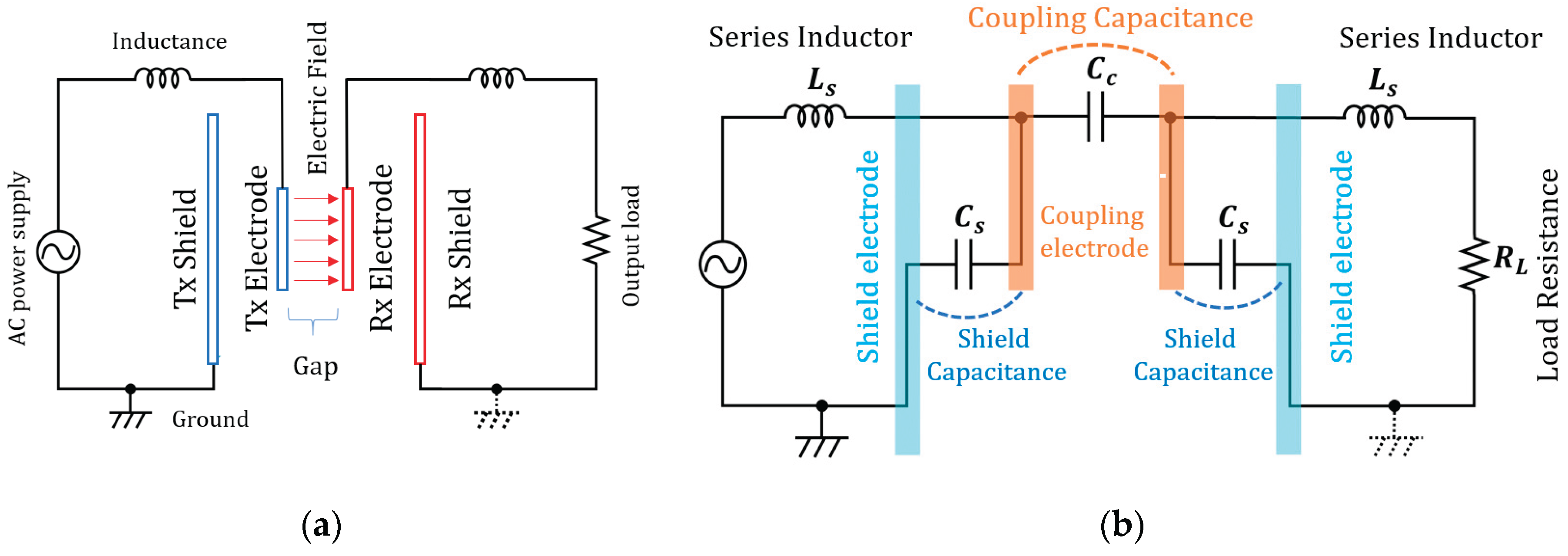
Figure 2.
Electrode materials evaluated: (a) Copper; (b) Aluminum ;(c) Ductile Cast Iron;(d) Structural Steel;(e) Carbon Steel.
Figure 2.
Electrode materials evaluated: (a) Copper; (b) Aluminum ;(c) Ductile Cast Iron;(d) Structural Steel;(e) Carbon Steel.
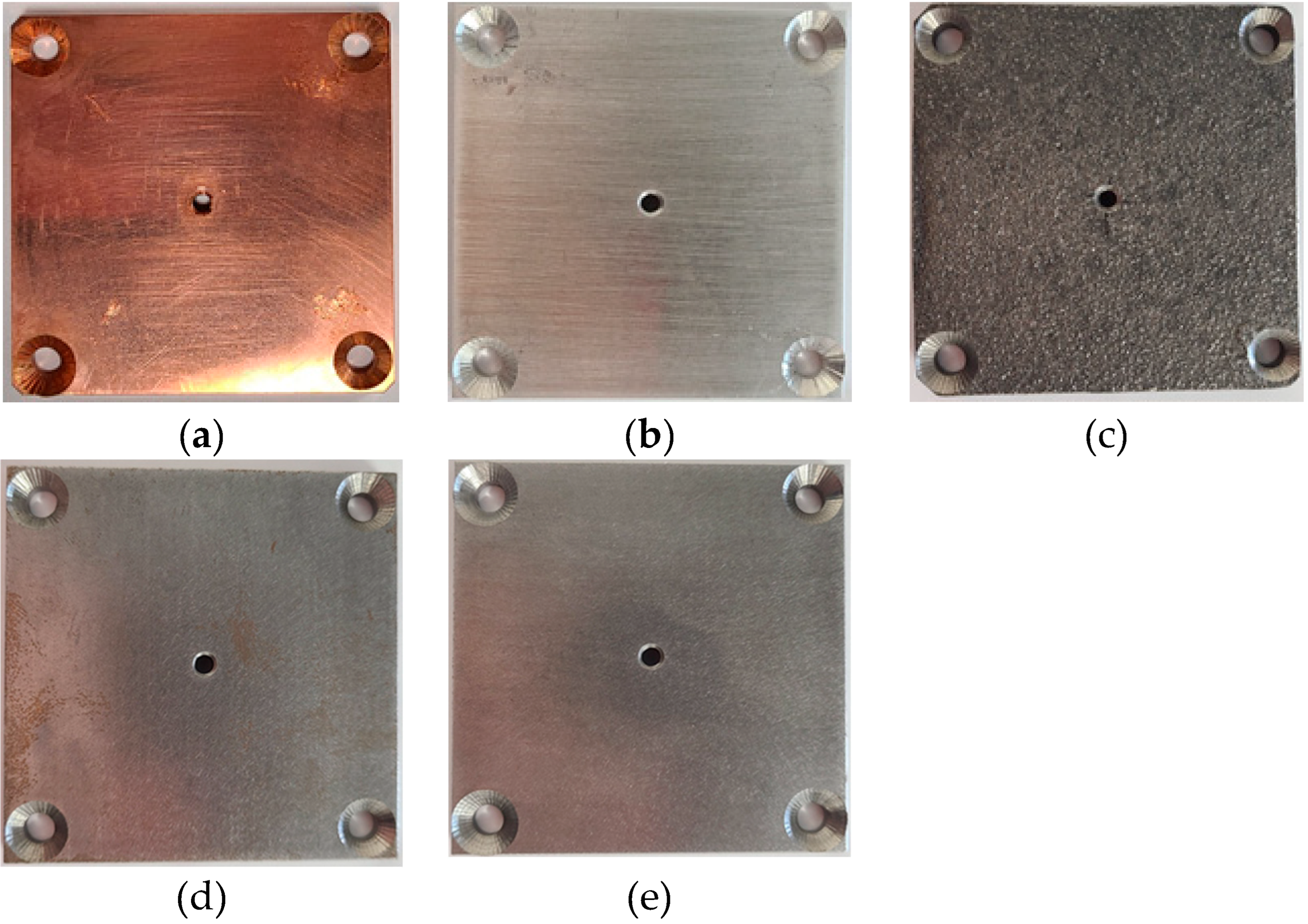
Figure 3.
Experimental setup and equivalent circuit: (a) Experimental setup; (b) equivalent circuit.
Figure 3.
Experimental setup and equivalent circuit: (a) Experimental setup; (b) equivalent circuit.
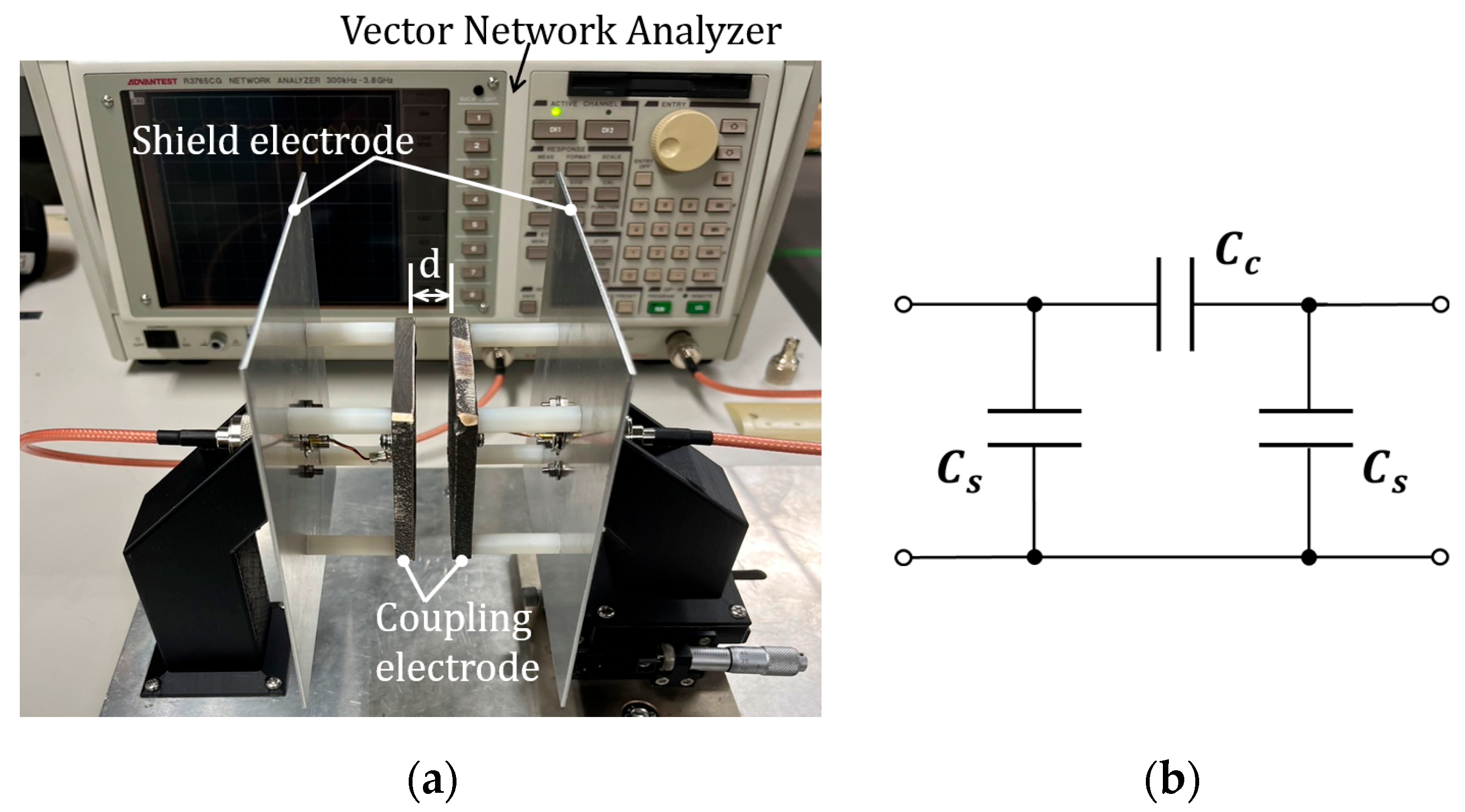
Figure 4.
Coupling capacitance for each electrode material Interelectrode distance characteristics.
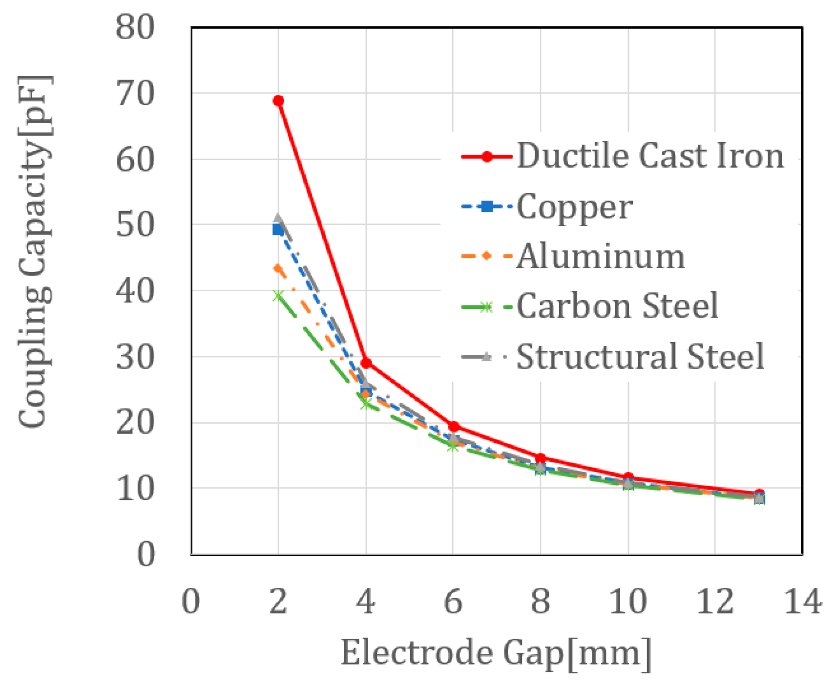
Figure 5.
TP appearance photos for evaluating differences in ductile cast iron surface properties: (a) As-cast surface; (b) Surface machining ;(c) Surface coating.
Figure 5.
TP appearance photos for evaluating differences in ductile cast iron surface properties: (a) As-cast surface; (b) Surface machining ;(c) Surface coating.
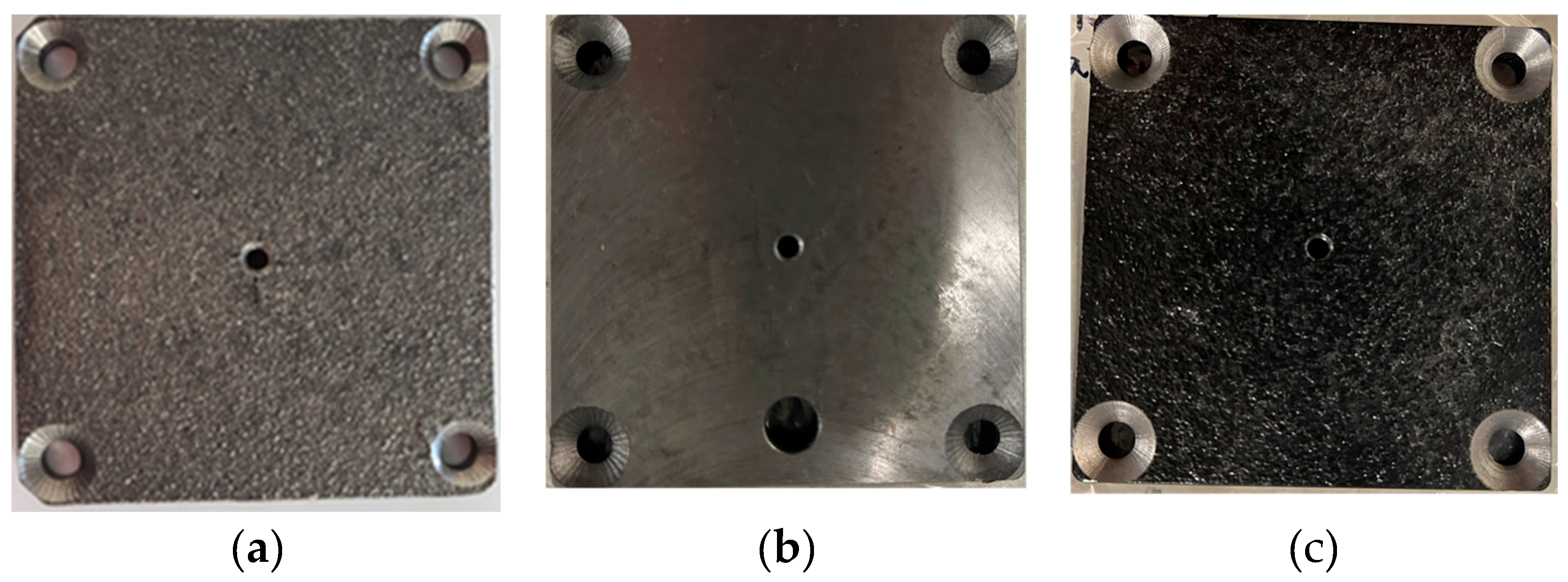
Figure 6.
Relationship between electrode gap and capacitance according to ductile iron surface properties.
Figure 6.
Relationship between electrode gap and capacitance according to ductile iron surface properties.
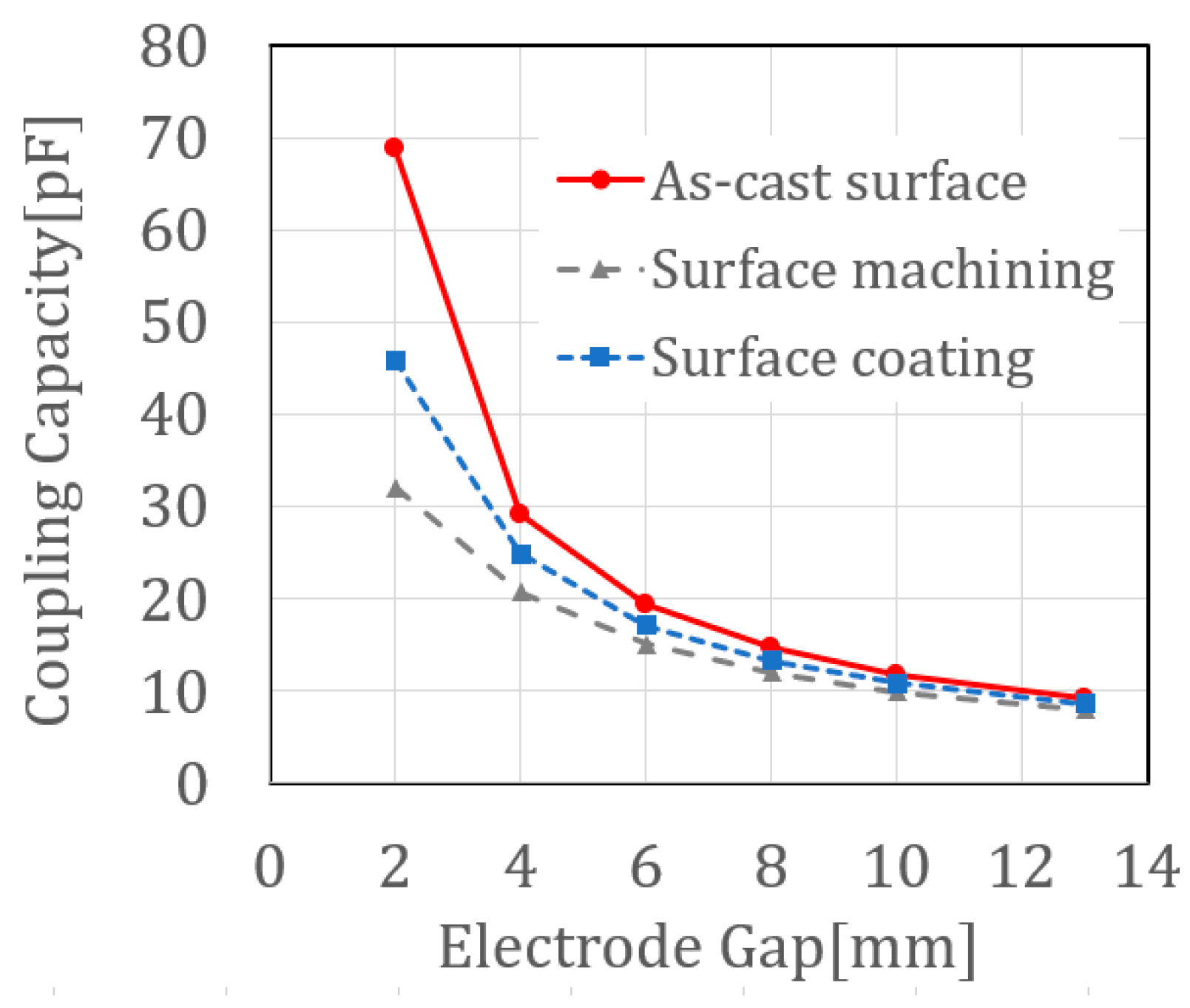
Figure 7.
4-plate S-CPT power transmission experiment configuration using cast iron covers as electrodes.
Figure 7.
4-plate S-CPT power transmission experiment configuration using cast iron covers as electrodes.
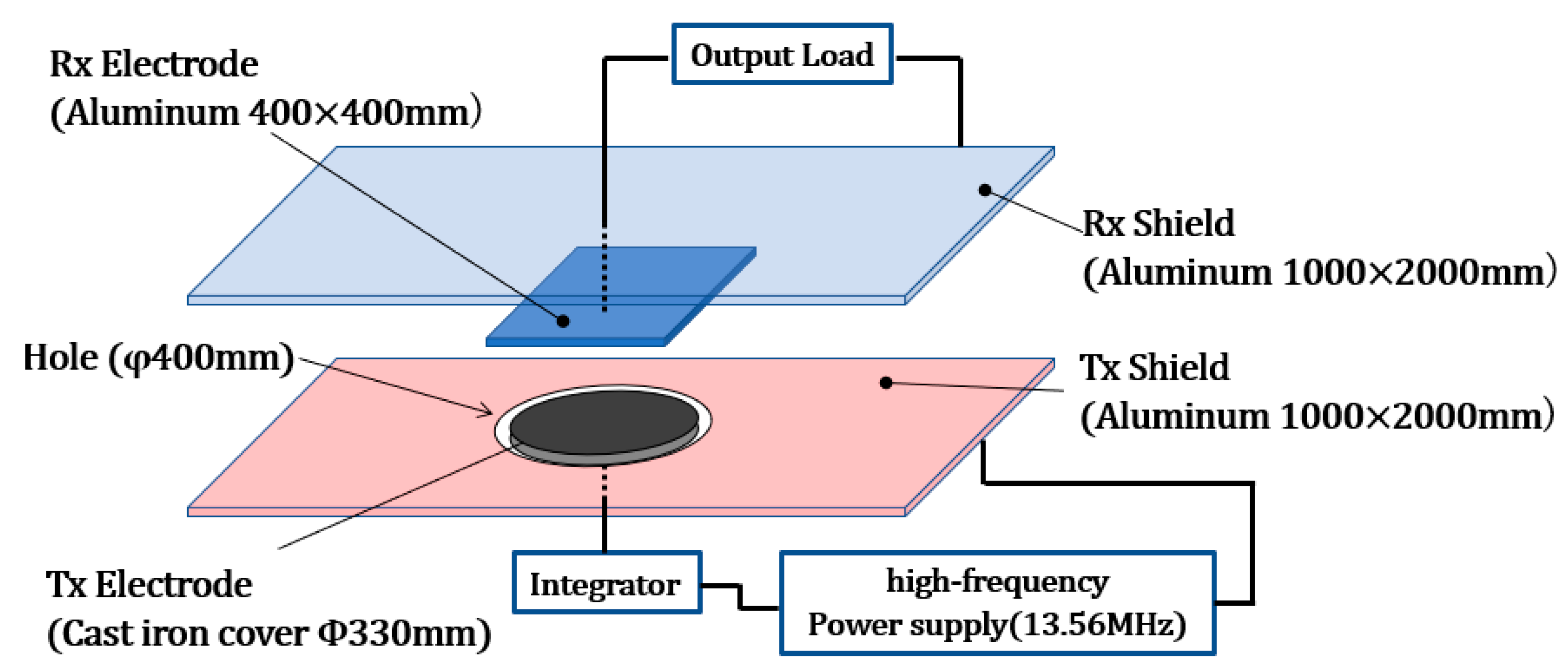
Figure 8.
Φ330 mm cast iron cover Stress distribution analysis using electrode structure and finite element method: (a) Φ330 mm cast iron cover electrode Main dimensions; (b) Stress distribution analysis using the finite element method.
Figure 8.
Φ330 mm cast iron cover Stress distribution analysis using electrode structure and finite element method: (a) Φ330 mm cast iron cover electrode Main dimensions; (b) Stress distribution analysis using the finite element method.
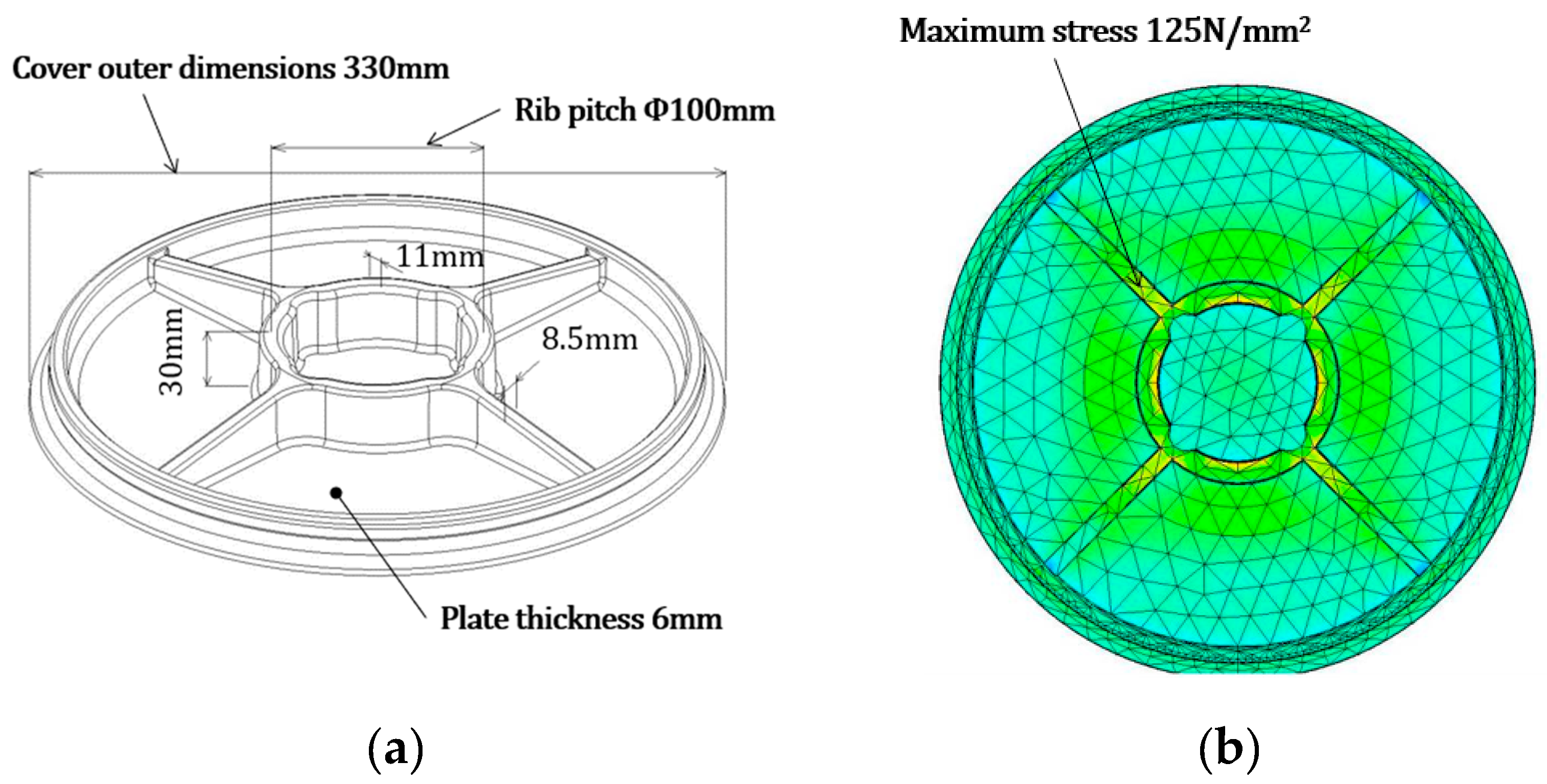
Figure 9.
Design and Impedance Matching of a 4-Plate S-CPT System: LTspice-Based Equivalent Circuit Analysis.
Figure 9.
Design and Impedance Matching of a 4-Plate S-CPT System: LTspice-Based Equivalent Circuit Analysis.
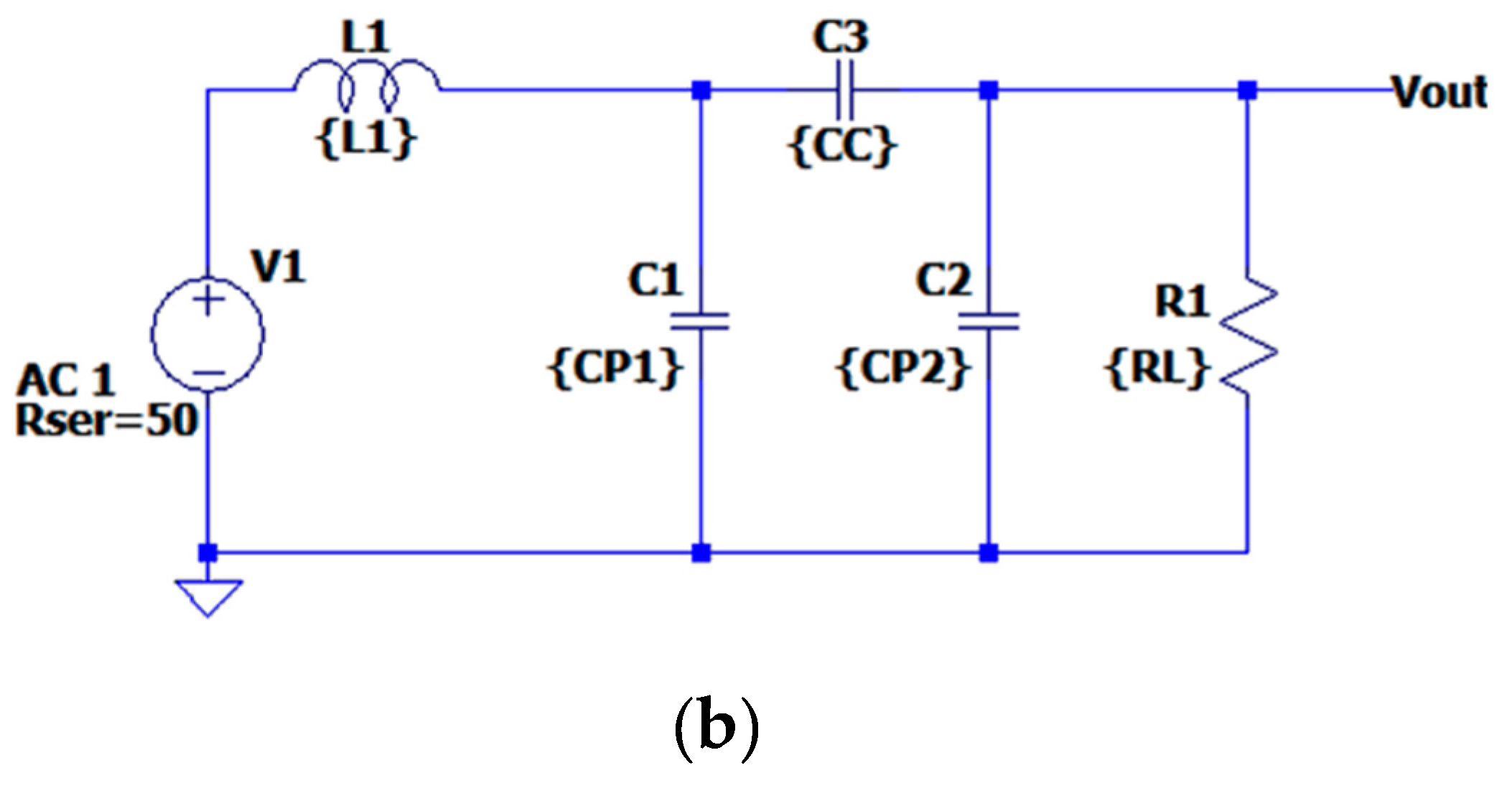
Figure 10.
Design and Impedance Matching of a 4-Plate S-CPT System: LTspice-Based Equivalent Circuit Analysis.
Figure 10.
Design and Impedance Matching of a 4-Plate S-CPT System: LTspice-Based Equivalent Circuit Analysis.
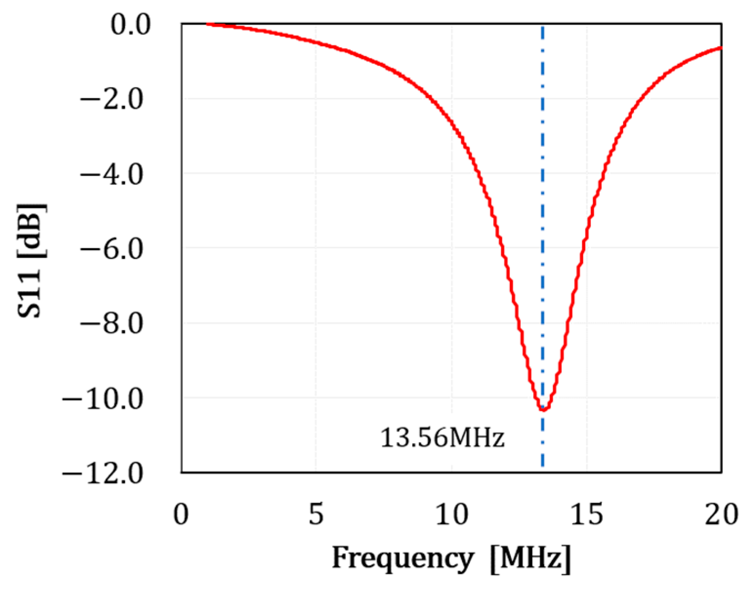
Figure 11.
EMI analysis results (a) EMI characteristics confirmation analysis model; (b) Electric field distribution (zero electrode displacement). (c) Electric field distribution (electrode position deviation 50 mm) (d) Electric field distribution (electrode position deviation 100mm).
Figure 11.
EMI analysis results (a) EMI characteristics confirmation analysis model; (b) Electric field distribution (zero electrode displacement). (c) Electric field distribution (electrode position deviation 50 mm) (d) Electric field distribution (electrode position deviation 100mm).
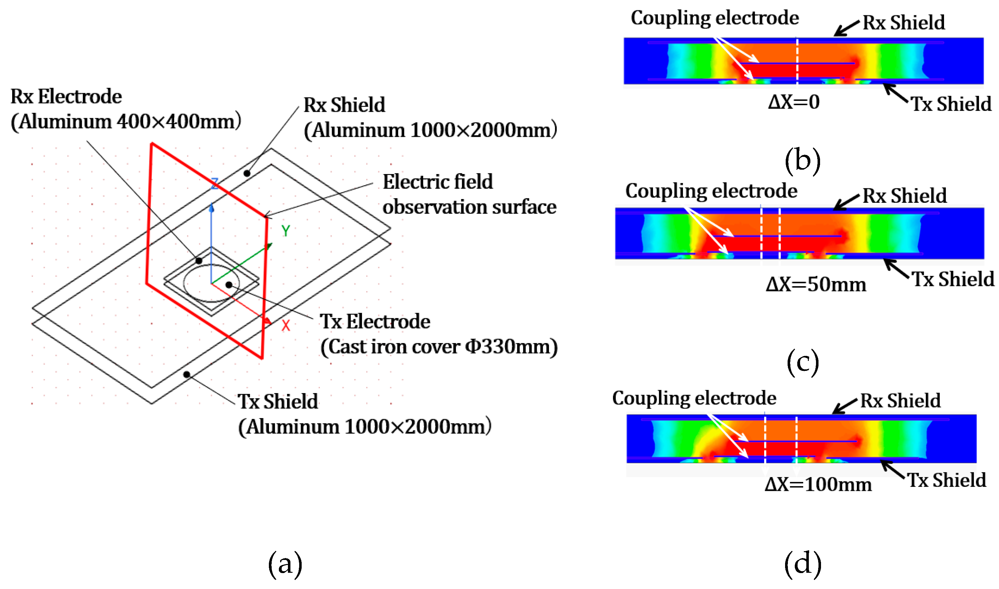
Figure 12.
S-CPT system mockup using cast iron covers as electrodes Power transmission experiment (a) Measurement setup; (b) Coupling electrode configuration using aluminum plates and cast-iron covers. (c) Cast iron cover electrodes installed inside the shield electrodes.
Figure 12.
S-CPT system mockup using cast iron covers as electrodes Power transmission experiment (a) Measurement setup; (b) Coupling electrode configuration using aluminum plates and cast-iron covers. (c) Cast iron cover electrodes installed inside the shield electrodes.
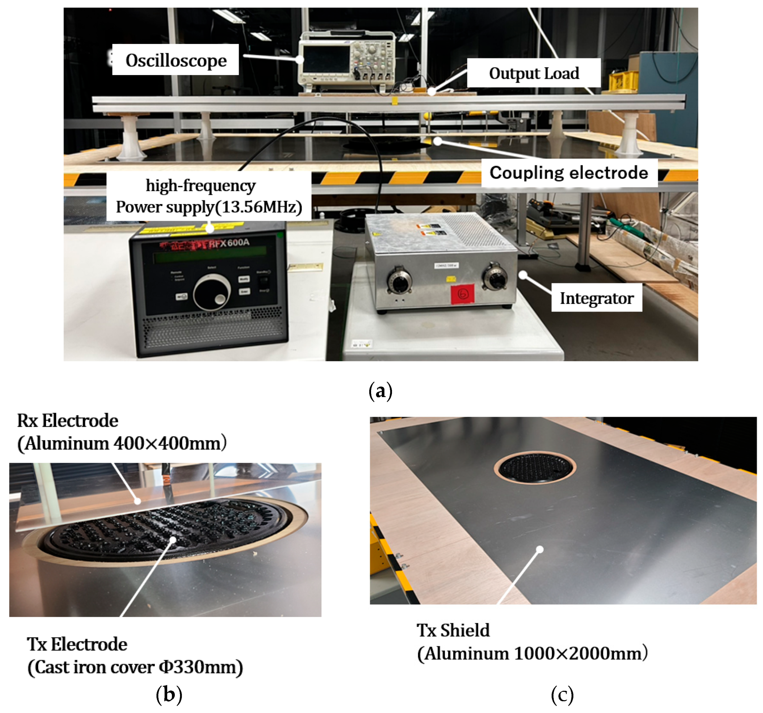
Figure 13.
Transmission efficiency versus input power under lateral misalignment.
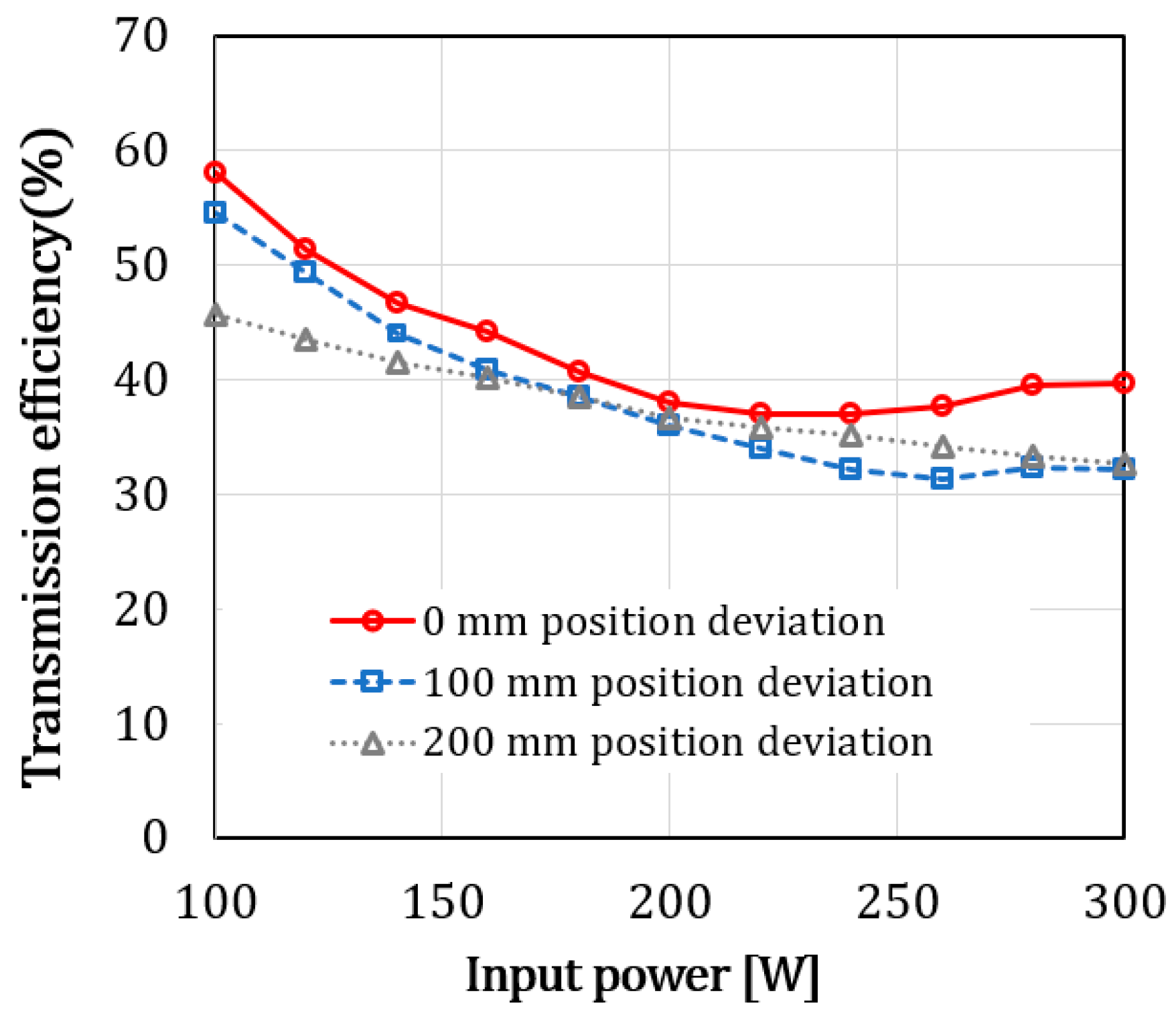
Figure 14.
System overview of the proposed S-CPT/DWPT segment.
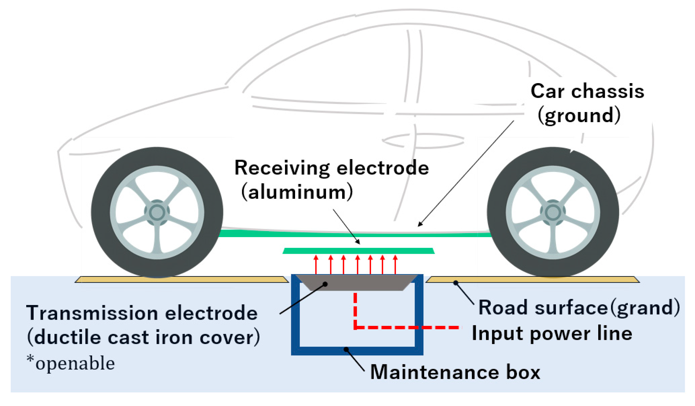

Table 1.
Typical electrical characteristics of evaluated materials.
| material name | Conductivity (σ) S/m |
Relative permeability (μr) | Specific resistance (ρ) (Ω·m) |
|---|---|---|---|
| Copper | 5.8 ×10⁻⁷ | 1.0 (nonmagnetic) | 1.7 × 10⁻⁸ |
| Aluminum | 3.5 ×10⁻⁷ | 1.0 (nonmagnetic) | 2.8 ×10⁻⁸ |
| Ductile Cast Iron | 0.9 to 1.3 ×10⁻⁶ | 80 to 200 | 7.7 to 11 ×10⁻⁷ |
| Structural Steel | 5.8 to 6.5 ×10⁻⁶ | 100 to 800 | 1.5 to 1.7 ×10⁻⁷ |
| Carbon Steel | 5.5 to 7.0 ×10⁻⁶ | 100 to 800 | 1.4 to 1.7 × 10⁻⁷ |
Disclaimer/Publisher’s Note: The statements, opinions and data contained in all publications are solely those of the individual author(s) and contributor(s) and not of MDPI and/or the editor(s). MDPI and/or the editor(s) disclaim responsibility for any injury to people or property resulting from any ideas, methods, instructions or products referred to in the content. |
© 2025 by the authors. Licensee MDPI, Basel, Switzerland. This article is an open access article distributed under the terms and conditions of the Creative Commons Attribution (CC BY) license (http://creativecommons.org/licenses/by/4.0/).
Copyright: This open access article is published under a Creative Commons CC BY 4.0 license, which permit the free download, distribution, and reuse, provided that the author and preprint are cited in any reuse.


