
Submitted:
10 July 2025
Posted:
11 July 2025
You are already at the latest version
Abstract
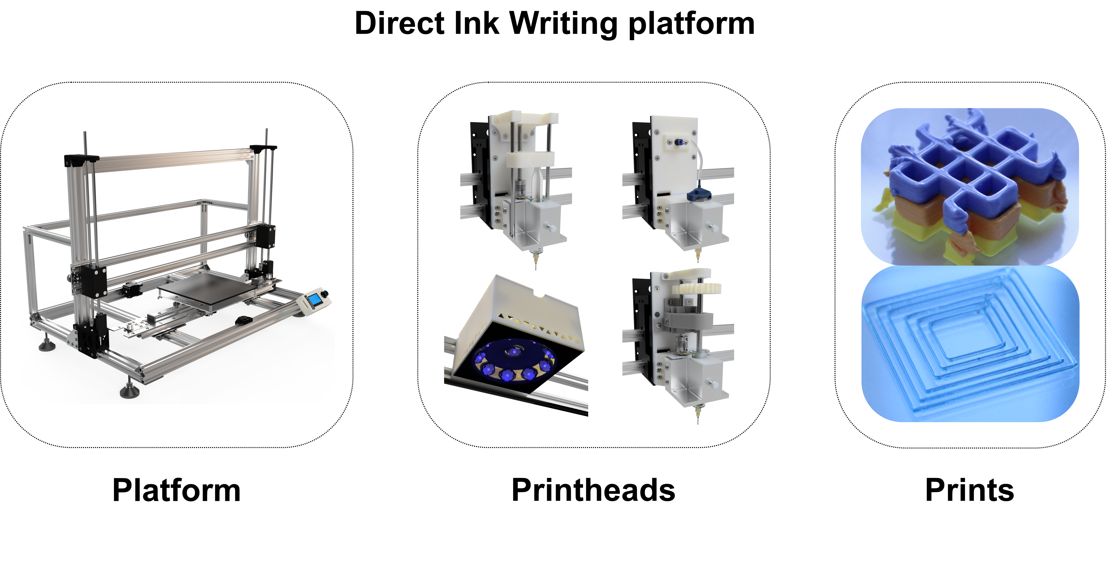
Direct Ink Writing (DIW) is an additive manufacturing technology that fabricates structures through layer-wise deposition of liquid materials. In this process, a liquid feedstock is dispensed onto a substrate via pneumatic or mechanical extrusion, followed by a solidification step, such as UV curing, for materials compatible with this approach.The growing demand for multi-material objects in fields like electronics and life sciences highlights DIW's potential to address these needs through its adaptability and precision. This study presents the development of a versatile multi-extrusion technology DIW platform designed with adaptability and reconfigurability at its core, ensuring compatibility with diverse material-specific processing requirements. Adopting a material-driven approach, the platform leverages principles of frugal innovation, incorporating in-house designed and 3D printed structural components to maximize accessibility and efficiency, as well as the use of artificial intelligence for the optimization of specific functionalities.Potential applications for this platform include 3D bioprinting, advanced electronics, and contributions to the circular economy, demonstrating its wide-ranging utility.
Keywords:
Direct Ink Writing
; Multi-Material 3D printing
; Frugal Research
; Artificial Intelligence
; Material Extrusion
1. Introduction
Additive manufacturing finds application across diverse fields, including electronics, automotive, energy storage, biomedical engineering, and soft robotics [1,2]. In these domains, 3D printing offers the dual advantage of reducing production complexity [3] and of enabling the fabrication of structures that are unattainable with conventional manufacturing techniques [4].
Although in all these fields the fabrication of multi-material parts has a primary role [2,3], the market offers very few examples of multi-material 3D printers endowing more than one deposition technique.
Direct Ink Writing (DIW) is an additive manufacturing technique used to fabricate three-dimensional structures. This process involves the deposition of a liquid material (ink) from a reservoir (cartridge) through a nozzle onto a computer-controlled translational stage in a layer-wise fashion. Once extruded, the ink undergoes solidification, resulting in a structure with the desired characteristics and properties [1].
For materials compatible with this approach, solidification is often achieved through UV curing, a widely utilized method [1].
DIW differs from other additive manufacturing technologies in what regards the variety of processable materials: while many techniques such as Fused Filament Fabrication (FFF) and Stereolithography are limited to a specific class, DIW allows the processing of any kind of liquid material which satisfies given requirements in terms of rheological behavior [1].
Such versatility makes this technology particularly suitable for diverse fields, such as 3D bioprinting [5], circular economy [6] and electronics [7,8] and for multi-material 3D printing [9,10].
The extrusion can be either pneumatic or mechanical. The former refers to an extrusion due to the application of a hydrostatic pressure via the use of compressed air.
Mechanical extrusion can refer to plunger or screw extrusion. In the first case, the extrusion is due to the application of a normal stress via the displacement of a plunger inside the cartridge. In the second case, the extrusion is due to the application of a shear stress via the rotation of a screw inserted in the cartridge [11,12].
Often, DIW is combined with in situ photopolymerization, allowing to extrude photo-curable resins, which are totally or partially crosslinked right after deposition [13,14,15].
Frugal innovation is defined as “doing more with less for more” [16], indicating a kind of research based on a limited use of resources and raw materials, reminding the modern-world challenge of dealing with a growing population and a reduction of natural resources.
The concept of frugality was first found in emerging markets, but it is growing in importance in advanced economies as well. Indeed, the European Union has underlined how frugal innovation may be a viable mindset to deal with the growing and alarming lack of raw materials that the world is facing in the last decades. In particular, it has been indicated as an option to be applied in advanced economies to crucial sectors such as the ones connected to Key Enabling Technologies [17].
Indeed, several works are present in literature, showing the use of frugal innovations in different fields of application, including microfluidic, chemistry, photovoltaic and additive manufacturing [18,19,20,21,22,23,24].
A side aspect of frugal innovation is the possibility for flexible and versatile products, which are particularly suitable for customization and reconfiguration [17].
Many examples of custom-made 3D printers [25,26,27,28,29,30,31,32,33,34,35,36] and 3D bioprinters [34,37,38,39,40,41,42,43,44,45,46,47] can be found in the recent literature.
A frugal approach can be noticed in some of them [31,36,38,40,43,44,45], but none of existing examples shows any particular attention for the flexibility, re-configurability and possibility for transformation of developed systems.
Artificial intelligence (AI) has become a cornerstone across diverse research domains, revolutionizing problem-solving approaches and enabling significant advancements [48,49,50,51]. Beyond popular generative models and machine learning techniques, mathematical optimization algorithms like genetic algorithms (GAs) are increasingly employed to design and optimize complex devices and systems [52,53,54]. GAs, which fall under the category of evolutionary computation, are inspired by natural processes such as selection, crossover, and mutation. These algorithms evolve solutions iteratively, navigating complex, high-dimensional parameter spaces to identify optimal results. Unlike traditional optimization methods, GAs can tackle problems where the search space is vast, non-linear, or poorly understood [55,56]. Their ability to adapt and find solutions in dynamic environments has led to a wide range of applications in material science [57], engineering [58], and biomedical fields [59], facilitating breakthroughs in device efficiency, performance, and functionality. The integration of AI, particularly through optimization techniques like GAs, is transforming research by addressing challenges that were previously computationally or experimentally unfeasible, fostering the development of innovative, optimized solutions across multiple disciplines [56].
The aim of this work is to present a frugal and AI enhanced multi-extrusion technology platform for multi-material DIW featuring several printheads of different types and a UV curing unit. The main points at the base of the project are the flexibility and re-configurability of the platform, which is intended to follow material-specific requirements to be easily adaptable and transformable basing on the specific needs. At this scope, the use of a frugal approach has been believed particularly appropriate: general purpose electronics and open-source software have been exploited, as well as 3D printed parts, which have been used as structural and functional components.
In addition, to optimize the UV curing unit for the specific application using commercial LEDs, artificial intelligence, specifically genetic algorithm, was employed to configure the LED arrangement, enhancing system performance while enabling easy, fast, and cost-effective reconfiguration if necessary.
Modularity has been granted in what regards both hardware and software, in order to allow fast and inexpensive implementation of new features or modification of existing ones.
The presence of different extrusion techniques on the same machine represents a huge potentiality in the field of DIW, allowing the processing of formulations showing different rheological properties and/or requiring different deposition conditions. Such platform shows potential use for the production of multi-material parts and in the field of material development, as a convenient tool in the characterization workflow of different material properties.
The main modules present on the platform are: a pneumatic extruder, a plunger extruder, a screw extruder and a UV curing module.
The resulting machine enables the processing of a wide variety of materials, with applications belonging to a broad range of fields, including tissue engineering (3D bioprinting [60]), electronics [61] and circular economy [62]. Notably, some works utilizing this machine have already been published in the areas of electronics [63] and circular economy [64,65].
2. Materials and methods
2.1. Printer Design and Configuration
The developed printer operates as a Cartesian system, with the print plate (210x210 mm, heated up to 100°C) moving along the horizontal x and y axes, and the printheads positioned on the vertical z-axis.
Motion is provided by stepper motors, with belts and pulleys driving the x and y axes and two 8 mm metric leadscrews providing precise motion to the z-axis assembly. The frame, measuring 800 × 540 × 520 mm, is constructed from general-purpose aluminum profiles (OpenBuilds) assembled using bolted joints.
The system is controlled by a BTT Octopus V1.1 motherboard (Bigtreetech). The open-source Marlin Firmware® was installed, offering high customization, reliability, and performance. Power is supplied by a 240 W 24V power unit.
All custom-designed and 3D printed structural components were produced using a commercial FFF printer (Original Prusa i3 MK3S+, Prusa Research). The printing parameters for these components were selected to maximize stiffness and are reported in Table 1.
The z-axis of the platform is designed to accommodate up to six printhead modules, offering significant flexibility for multi-material and multi-extruder printing.
Each printhead module consists of two main components: a support and an extruder. The support is fixed to the z axis and equipped with solenoid valves, which are connected to HEATER pins on the motherboard and allow for precise vertical displacement of the active extruder. During printing, the valves lower the active extruder into its position, while during the idle state of the extruder, they lift it away from the print area. This dynamic positioning helps prevent accidental collisions of idle extruders with the part being printed, ensuring uninterrupted printing and maintaining print quality.
Being connected to the motherboard, solenoid valves and therefore extruder vertical displacement can be controlled exploiting G-code commands.
Each extruder is mounted on the support and is made of a cartridge holder and extruder-specific components, tailored to the type of extrusion being used (whether pneumatic, plunger, or screw-based). The cartridge holders are fabricated from milled aluminum, providing robust structural support for the extruders. In addition, these holders are designed with the capacity to integrate a thermocouple and a Peltier plate. This feature opens up the possibility of developing a temperature control system that can regulate the temperature of the extruder, enabling both heating and cooling. Such a system would enhance the control over material flow, particularly for temperature-sensitive materials, and further improve the flexibility and precision of the platform.
All extruders are designed to be used with interchangeable disposable nozzles, which can be securely mounted to cartridges using a Luer Lock joint. The nozzles are available in different diameters, including both tapered and cylindrical designs, allowing for flexibility in extrusion processes.
CAD files of the main structures, extruders and UV curing unit are available in supplementary information.
2.2. Extruders Design
2.2.1. Pneumatic Extruder
Pneumatic extrusion is achieved using pressurized air to extrude material through a nozzle. A pneumatic extruder was designed by modeling the components in Fusion 360, printing the necessary parts, purchasing custom-made aluminum components, and assembling all parts, including the electronics and pipelines. The system uses pneumatic printheads that accommodate syringes of different sizes (3 mL, 10 mL, 55 mL), with an oil-less air compressor delivering up to 8 bar of pressure. Airflow control is managed through a dual-valve system that ensures precise start-stop extrusion control. Specifically, one valve applies pressure inside the cartridge to initiate material extrusion, while the second valve releases residual pressure in the pipeline, enabling instantaneous cessation of extrusion when required. The valves are connected to FAN pins of the motherboard and can be controlled via G-code commands during the print.
2.2.2. Plunger Extruder
The plunger extruder was designed using Fusion 360 to model the components, followed by 3D printing the necessary parts, purchasing custom-made aluminum components, and assembling all pieces and electronic. The system uses a piston to expel material from a syringe, with key components including a stepper motor, leadscrew, and syringe. The motor drives the leadscrew to move a 3D printed carriage that displaces the syringe piston, while a linear guide ensures vertical displacement and stability. The extruder is compatible with syringes of different sizes (10 mL, 20 mL, 60 mL), offering flexibility for various material volumes. The stepper motor is directly connected the motherboard and can be controlled via G-code commands in an analogous way as for FFF extruders.
2.2.3. Screw Extruder
The screw extruder, designed for DIW, features an 80 mm long screw that operates at room temperature. The extruder’s kinematics include a stepper motor, which drives a gear mechanism connected to the screw by means of its internal shaft, controlling the rotation. The stepper motor is directly connected the motherboard and can be controlled via G-code commands in an analogous way as for FFF extruders.
The entire extruder was designed by modeling the components in Fusion 360, followed by 3D printing the necessary parts, purchasing custom-made aluminum components, and assembling all parts and electronics.
The screw was designed ad-hoc and consists of two components: an external shell and an inner aluminum shaft. The external shell has been modeled and 3D printed using Acrylonitrile Styrene Acrylate (ASA), providing the external geometry of the screw. ASA has been chosen for its higher mechanical strength and wear resistance, if compared to other traditional polymers for FFF, and for the possibility to be polished by exposure to acetone vapors, to achieve a smooth surface. Indeed, the 3D printed shell has been exposed to acetone vapors for 30 minutes and dried for 24 hours at room temperature. The inner shaft, an 8-mm diameter aluminum bar, has been secured to the shell by filling the cavity with epoxy resin and transfers the motion from the gears to the screw. A 20 mL syringe was used as the disposable barrel.
2.3. UV Curing Unit
A UV curing unit has been designed for the printer, utilizing 365 nm LEDs (Intelligent LED Solutions ILH-XP01-S365-SC211-WIR200. Emitted power 180 mW, radiance angle 55°), mounted on a 3D printed shell. The LEDs are powered by a 7.5 V external power supply and can be switched on and off through G-code commands. A MOSFET (IRFZ44N) has been placed between the power supply and the LEDs, with its gate pin connected to a FAN pin on the motherboard, enabling instantaneous and automatic control during the print.
A constant light intensity across a specified surface is necessary to ensure uniform curing throughout the entire printed sample, therefore an optimization process for the number and arrangement of LEDs was performed.
The designated target surface was defined as a circular area with a diameter of 90 mm, and a minimum average intensity of 25 mW/cm2 was set as the desired threshold (value selected basing literature review [66,67,68,69,70,71,72,73]).
The assumed structure of the UV curing unit comprises 1 (or 0) LEDs positioned at the center, directed downward, surrounded by two concentric rings of LEDs with and inward or outward inclination angle.
Basing on such structure, 12 geometrical variables have been defined and are listed in Table 2.
The light intensity profile on the target surface was defined as a function of these variables, and its peak-to-peak distance was minimized within the surface domain. The optimization involved 12 variables, three of which were integer parameters. Traditional optimization tools would have resulted in excessive computation times; therefore, a genetic algorithm was employed to efficiently address the problem and achieve the desired uniformity in light intensity. The function definition and optimization was carried out through a Matlab script.
After the optimization, the 12 optimized values of geometrical variables have been used as parameters for the parametric modeling of the shell on which LEDs are mounted. Such component has been 3D printed via LCD 3D printing (Phrozen Sonic Mini 8K 3D printer) with a layer height equal to 0.05 mm, using a commercial resin (Anycubic ABS-like Resin+).
An external shell has been designed for the UV and has been 3D printed via FFF using aforementioned printing parameters (Table 1).
To characterize the actual emission of the UV curing unit and validate the optimization process, the light delivered to the target surface was measured using a SpectriLight ILT950 spectroradiometer (International Light Technologies, Peabody, USA). Light intensity was evaluated at 81 distinct points arranged in a 120 × 120 mm horizontal square grid, consisting of 9 points in each direction with 15 mm spacing between them. The central point of the grid was vertically aligned with the central LED of the UV curing unit. To ensure compliance with the optimized geometrical variables, the vertical distance between the UV unit and the spectroradiometer sensor was adjusted accordingly.
2.4. Machine Control
The overall functioning of the platform is analogous to that of a standard multi-extruder 3D printer. Before initiating the printing process, manual Z-axis leveling is necessary to accommodate variations in nozzle lengths or cartridge volumes, given that both components are interchangeable. This adjustment ensures precise alignment and consistent extrusion during the printing process.
When an extruder is required, it is lowered into position, and material is extruded according to the specific type of extruder in use. Once extrusion is completed, the extruder is lifted, and the subsequent extruder, if needed, is lowered.
As for the UV curing process, it is performed after the deposition of each layer. The print plate moves into alignment with the UV curing unit, the LEDs are activated for a specified duration, and then the print plate returns to its previous position to continue printing.
All elements of the printer are controlled via G-code commands. To streamline the workflow, a complete dedicated slicer software was not implemented; instead, an alternative approach was adopted. PrusaSlicer 2.5.0 was selected as the slicer, utilizing a custom machine preset tailored to the specific platform. G-code files generated by PrusaSlicer are subsequently processed through a Python-based tool developed to incorporate custom commands specific to the printer’s unique hardware and electronics.
This tool automates routines such as extruder activation (lifting and lowering), material extrusion, and UV curing. To enhance usability, the Python tool was converted into a PC-compatible executable application with a graphical user interface, simplifying its operation. The application handles all necessary post-processing, ensuring the G-code is seamlessly adapted to the custom configuration of the machine.
In particular, the tool adds specific temperature commands to the G-code whenever an extruder needs to be lifted or lowered. This is because the solenoid valves controlling these actions are connected to the motherboard’s HEATER pins, as previously described. Additionally, commands related to cooling are incorporated to manage the operation of pneumatic extruder valves, which are responsible for material extrusion. These valves are connected to the FAN pins on the motherboard, as noted earlier. Furthermore, the tool adds motion and cooling commands to control the UV curing process, with the MOSFET regulating the LEDs connected to the FAN pins on the motherboard, as previously stated.
2.5. Machine Testing
The platform tested to assess both the functionality of the extruders and the reliability of the control strategy. Several parts were printed using all the extruders and different materials, including both single-extruder and multi-extruder prints. Details about these prints can be found in the supplementary information.
To assess the UV curing unit’s efficacy in crosslinking photo-crosslinkable resins, samples were printed using a pneumatic extruder. After printing, each part was subjected to curing for durations of 5, 10, and 15 seconds. Three samples were printed for each curing duration. The gel content of each sample was then determined by immersing it in stirring acetone (200 ml acetone per gram of sample) for 24 hours. The samples were subsequently dried in a vacuum oven at 60°C for at least 24 hours, with weight measurements taken every 6 hours until stability was achieved in two consecutive measurements. Gel content was calculated as the ratio of the final weight to the initial weight.
Three materials with different rheological properties were used for the production of the printed parts. Material 1 is a commercial cosmetic cream, characterized by high viscosity and yield stress. Material 2 is a gelatin-based hydrogel commonly used in 3D bioprinting, with low yield stress and viscosity. Material 3 is a commercial UV-curable resin, used to test the effectiveness of the UV curing unit. Further details are provided in the supplementary information.
2.6. Cost Analysis
The approximate cost of the machine has been evaluated to compare the self-production cost with the price of a commercial Direct Ink Writing (DIW) setup. This cost assessment takes into account the materials used for 3D printing, custom components, electronics, and the integration of various extrusion technologies. By comparing these expenses with those of commercially available systems, the evaluation provides insights into the cost-effectiveness and potential advantages of self-manufacturing the platform. The comparison also highlights the economic feasibility of adapting the design for specific research needs, offering a more affordable and customizable alternative to off-the-shelf solutions.
3. Results and Discussion
3.1. Printer Design and Configuration
A multi-technology platform for multi-material Direct Ink Writing (DIW) and UV curing has been successfully designed and developed (Figure 1).
The platform integrates various extruding technologies, specifically pneumatic extrusion, plunger extrusion, screw extrusion, and a UV curing unit, providing significant flexibility for a wide range of applications. The design of this platform was driven by a frugal approach, aimed at enhancing adaptability and customizability according to material-specific requirements. This strategy allows for a high degree of versatility, making the machine suitable for a variety of fields, including tissue engineering (3D bioprinting), circular economy, and electronics.
Additionally, the machine can be reconfigured in a fast and cost-effective manner to incorporate new features, ensuring continued adaptability. Artificial intelligence, in the form of a genetic algorithm, was employed to optimize the design of the UV curing unit, minimizing its peak-to-peak light intensity profile. Mounting LEDs on 3D printed hardware further enhances the system’s flexibility, allowing for straightforward modifications to the unit’s wavelength, light intensity, and target surface extension as required.
One of the most distinctive features of the platform is its modular design for the printheads. This modularity allows for quick and easy swapping of the printheads, providing users with the flexibility to adjust the number and type of extruders according to the specific requirements of their projects. The design accommodates multiple extrusion technologies—such as pneumatic, plunger, and screw extruders—on the same machine, offering significant versatility in material deposition. After reconfiguring the printhead setup, the platform is ready for operation almost immediately, ensuring minimal downtime. The new configuration of extruders can be effectively controlled by making simple adjustments to the G-code converter script, which automatically adapts to the new setup. This streamlined process highlights the machine’s user-friendly interface and rapid adaptability, making it highly suitable for diverse applications where quick reconfiguration is essential.
The developed printer is a Cartesian system, in which the build plate moves along the horizontal x and y axes, while the printheads are positioned on the vertical z-axis. This design involves moving the build plate instead of the extruder assembly in the horizontal plane, as the extruders are relatively heavy. This approach avoids the need to displace the mass of the printheads during printing, reducing motor effort and helping to maintain accuracy by minimizing potential vibrations.
The machine features a 210 x 210 mm print bed with a temperature control system capable of reaching temperatures between room temperature and 100°C. This temperature range ensures compatibility with a broad spectrum of materials. In addition, the system’s precision allows for accurate deposition, with an XY plane accuracy as low as 50 µm and a Z-axis resolution of 10 µm. These capabilities ensure high-quality prints with fine details, making the system suitable for many research applications that require precise spatial control over deposition. The machine’s benchtop design allows it to be placed into a fume hood for processing hazardous materials (with the added benefit of disposable cartridges and nozzles) or into a biological hood for clean environments, ideal for applications in tissue engineering.
3.2. Extruders
3.2.1. Pneumatic Extruder
Pneumatic extrusion uses pressurized air to expel material from a cartridge through a nozzle, offering simplicity, reliability, and minimal maintenance. By adjusting air pressure, it can handle materials of varying viscosities without the need for high-torque stepper motors, reducing system weight and complexity. This makes the system more efficient and versatile compared to mechanical extrusion, which requires heavier components and higher power [12]..
The printer features pneumatic printheads (Figure 2a) designed to accommodate commercial syringes of various sizes—3 mL, 10 mL, and 55 mL—as material reservoirs. It is equipped with an oil-less air compressor capable of delivering up to 8 bar of pressure. The use of disposable syringes provides flexibility, enabling users to choose syringe sizes based on material volume needs. Compatibility with Luer Lock nozzles expands material and dispensing configuration options. The cartridge is sealed with an airtight cap connected to a pipeline that supplies compressed air, generating the pressure needed for extrusion.
One solenoid valve, controlled by the motherboard, applies the pressure on the cartridge, enabling the extrusion process by switching the flow on and off as required. The pressure level is manually adjustable via a manometer, giving users the ability to fine-tune the applied pressure in real-time based on material behavior during printing. This manual control was intentionally chosen over automatic pressure regulation to allow for greater user flexibility in the deposition process.
The printer uses a dual-valve system for precise start-stop control of extrusion. The primary solenoid valve regulates the air supply to the cartridge, activating or deactivating the flow of material as needed. The secondary solenoid valve is responsible for releasing residual pressure when extrusion is stopped. During printing, this valve remains closed to maintain pressure in the system, but it briefly opens after extrusion to release any residual pressure in the pipeline and prevent material leakage. This system ensures controlled extrusion, avoiding issues like over-deposition or unwanted drips.
The coordination of these valves is managed through a combination of G-code commands and hardware wiring. The valves are connected to pins on the motherboard typically assigned to heater control, and activating a particular valve is achieved by sending a G-code command to set a higher temperature. This powers the corresponding pin, thereby switching on the valve and enabling extrusion control.
3.2.2. Plunger Extruder
Mechanical plunger extrusion uses a piston to push fluid from a cartridge, offering more precise volumetric control over the extruded material compared to pneumatic systems. While this approach is more complex due to the moving parts and mechanical joints involved, it provides a key advantage in that the extrusion process is independent of the material’s rheological properties, allowing for consistent material flow. Mechanical plunger extrusion is particularly advantageous for low-viscosity materials, as this way it is possible to perform retractions and effectively prevent leakages [11].
To enable plunger-based extrusion, the printer integrates a custom-designed plunger extruder (Figure 2b), featuring key components such as a stepper motor, leadscrew, and syringe. The stepper motor is securely mounted alongside the syringe within the extruder’s main body. The motor’s rotation drives the leadscrew, which moves a 3D printed carriage along a vertical axis. The syringe piston is attached to this carriage, ensuring that the motor’s motion directly translates into precise vertical displacement, allowing for controlled material flow.
To enhance operational accuracy, a linear guide is incorporated into the design. This guide ensures smooth, stable motion by preventing any unintended rotation or non-vertical displacement of the 3D printed carriage, thus increasing system reliability.
The extruder is designed for compatibility with syringes in various sizes, including 10 mL, 20 mL, and 60 mL, offering flexibility in material volume and accommodating a broad range of applications.
The stepper motor of the plunger extruder can be connected to the pins dedicated to the extruder stepper motor, as originally intended for an FFF printer. By utilizing these existing connections, the motor can be directly controlled through G-code commands, without requiring special conversion or additional modifications.
3.2.3. Screw Extruder
The printer features a screw extruder designer for the scope, shown in Figure 2c.
Screw extruders used in Direct Ink Writing (DIW) differ significantly from their industrial counterparts in both size and operating conditions. DIW screws are generally much smaller, often only a few centimeters in length, and they operate under mild temperature conditions. Contrarily, industrial screw extruders are designed to handle high pressures and temperatures for continuous production [74,75].
The flow rate in these systems depends on a complex interplay of screw geometry and material properties, making precise modeling challenging [76].
Designing and producing screws in-house offers the flexibility to customize geometry, thereby expanding the range of materials that can be processed. In this case, a plastic screw was chosen as a viable alternative to a metallic one. A multi-material approach was implemented to address the mechanical stresses associated with the application, dividing the screw into two components: the external shell and the inner shaft.
The external shell, crafted from Acrylonitrile Styrene Acrylate (ASA), was selected for its higher mechanical strength, chemical resistance and wear resistance if compared with typical polymers for FFF such as Polylactic Acid and PETG. The possibility to be polished via acetone vapors allows to reduces friction and also enhances wear resistance (Figure 3a). The shell, 3D printed using FFF, has a thickness of 0.8 mm and features two 8-mm holes to securely insert the shaft and ensure proper alignment (Figure 3b).
The inner shaft, made from an 8-mm diameter aluminum bar, provides the necessary structural strength. Once the shaft is inserted into the shell, epoxy resin is poured into the remaining cavity, securing the shaft and reinforcing the structure. The final assembly integrates the surface finish and geometry of the ASA shell with the stiffness of the aluminum shaft and the added reinforcement from the epoxy resin, resulting in a durable screw suitable for the processing of liquid and paste-like materials at mild temperatures.
Considering the conditions typical of Direct Ink Writing (DIW) processes, metallic barrels were deemed unnecessary. Instead, commercial 20-mL plastic syringes were used as barrels. This design choice ensures compatibility with widely available needles and nozzles, which serve as dies, making maintenance easier and enabling quick, cost-effective changes.
In this case, extrusion is driven by the rotation of a stepper motor, which is transferred to the screw via a gear mechanism. Unlike plunger extrusion, screw extruders do not provide volumetric control over extrusion. In fact, the relationship between the screw’s angular velocity and the material flow rate is complex and relies on factors such as screw geometry, material properties, and temperature. While the analytical and numerical solutions to this problem can be complex [77], the flow rate can be manually adjusted during printing, similar to the approach used on commercial FFF printers in order to obtain an appropriate flow rate for the current printing parameters.
3.3. UV Curing Unit
A dedicated UV curing unit has been developed for the printer. In standard UV-assisted DIW, the material is typically exposed to UV light immediately after extrusion, facilitating almost instantaneous crosslinking. This method works well for highly reactive resins but becomes impractical for materials that require longer curing times. In such cases, the printing speed and curing speed are inherently linked, complicating the process. Additionally, the risk of nozzle clogging due to uncontrolled crosslinking is a common challenge [62].
To overcome these challenges, a different approach has been implemented. The printer first prints a layer, and then it is exposed to UV light from a dedicated UV unit located away from the nozzle. This method enables each layer to be printed in the same manner as traditional DIW, followed by independent curing. This process offers greater flexibility in choosing materials and adjusting printing parameters.
The LED arrangement required to deliver a constant light intensity over a 90 mm circular surface was optimized using a genetic algorithm. The problem, which is a type of Mixed-Integer Nonlinear Programming problem, involved 12 variables, with some of them constrained to integer values. The genetic algorithm, a form of artificial intelligence, was employed to efficiently solve the problem, significantly reducing computational time.
By building a custom unit with LEDs mounted on 3D printed hardware, the system’s flexibility is further enhanced, allowing easy adjustments to the wavelength, light intensity, and target surface area as needed. Automatic optimization through the genetic algorithm accelerates the design process, enabling rapid reconfigurations for different requirements.
The optimized values of the 12 geometrical variables defined to describe the UV curing unit are listed in Table 3 and have been evaluated running the optimization code with the inputs and constraints listed in supplementary information.
The optimized UV curing unit resulted in a central LED positioned 31 mm above the target surface, directed downwards. Surrounding this central LED is a ring of 9 LEDs arranged in a circular formation with a radius of 50 mm, rotated 100° relative to the vertical axis. These LEDs are placed at a height of 19 mm, with an inward angle of 46°.
The optimized (theoretical) intensity profile is represented in Figure 4. Following optimization, the theoretical intensity profile achieved a mean value as high as 25.2 ± 1.0 mW/cm2. The utilization of LEDs, representing the fraction of light power effectively delivered to the target surface, is 89%. This indicates that the arrangement of LEDs efficiently directs nearly all emitted light towards the target surface, with only a small fraction being dissipated in the surrounding area.
The UV curing unit, shown in Figure 5, displays the LED arrangement designed according to the optimized values of the geometrical variables. The final dimensions of the external shell are 150x140x82.5 mm.
The light intensity profile emitted by the UV curing unit was measured experimentally, and the corresponding data points are shown in Figure 5. Upon comparison with the theoretical profile, it is evident that the experimental results closely align with the expected distribution, demonstrating the accuracy of the system’s design. However, some minor discrepancies were observed, primarily near the center or at points beyond the target surface. These slight variations could be attributed to factors such as minor imperfections in the LED arrangement or slight misalignments. Nonetheless, the overall consistency between the experimental and theoretical profiles confirms the effectiveness of the UV curing unit’s design.
3.4. Machine Control
The process of producing a 3D printed object typically involves several steps. First, a CAD model of the object is designed, followed by the use of a slicer to generate the corresponding G-code. This G-code instructs the printer on how to construct the part layer by layer. The G-code is then uploaded to the printer, and the firmware interprets these instructions into electrical signals that control the printer’s components.
As previously described, the G-code generation for the custom platform starts with creating an initial G-code using PrusaSlicer® (version 2.5.0). This G-code is then modified to suit the requirements of the multi-technology platform through a custom-developed Python tool.
The initial steps of CAD design and G-code generation are similar to those used in commercial FFF 3D printing. Afterward, the generated G-code is further processed using the Python-based tool developed specifically for this purpose. This tool automates the modification of the G-code to adapt it to the machine’s specific configuration, including commands for extruder activation, extruders lifting and lowering, and UV curing routines during the printing process.
To make the tool more accessible, it was transformed into a user-friendly executable application with a graphical interface. This allows users with limited programming knowledge to use the tool easily. Once the G-code is processed, the modified version is uploaded to the printer, where the firmware reads it and controls the printing process accordingly. This workflow minimizes the need for extensive training, as users can operate the system similarly to a commercial FFF printer, with the additional step of interacting with the post-processing tool.
The graphical user interface is displayed in Figure 6. As shown, it features several key fields for user interaction. One field allows the user to select the folder containing the G-codes to be converted. Another field enables activation of the UV curing process, where the user can specify the duration. Additionally, a field is provided for inputting Z-coordinate values obtained from manual leveling. These inputs are utilized by the tool to modify the G-codes accordingly. The tool generates new versions of the files without overwriting the original G-codes, which facilitates easier usage and eliminates the need to regenerate the G-codes from scratch in PrusaSlicer if mistakes are made or if different DIW printing parameters are required. The program stores the last used settings to ensure they are preserved between sessions.
3.5. Machine Testing
The platform was tested to evaluate the functionality of the extruders and the reliability of the control strategy. The printed parts (Figure 7) were assessed for several key indicators that reflect the effectiveness of the machine’s design and performance.
First, the absence of distortions in the printed parts compared to the original CAD models indicated effective kinematic control, proper assembly, and the orthogonality of the machine’s axes. The precise stacking of layers, particularly in multi-extruder prints, signified well-designed printheads with correct nozzle positioning. Furthermore, the absence of uncontrolled nozzle displacements suggested that the structural components of the machine have sufficient stiffness to prevent misalignments during operation.
Another critical indicator was the consistent material flow during deposition. For materials with low yield stress, such as hydrogel, the absence of post-extrusion flow indicated that the vibrations generated during printing were within acceptable limits. This suggests that the machine’s design mitigates issues like uncontrolled material movement, ensuring precise extrusion. Moreover, the absence of collisions with printed parts confirmed that the G-code generation and machine operation were correctly implemented. Prints involving multiple tool changes were completed without any collisions nor stops, further demonstrating the effectiveness of the G-code conversion process.
The successful execution of both single- and multi-extruder prints without significant issues confirmed the robustness of the hardware and software design. The printed parts showed high fidelity to the CAD models, indicating that the mechanics, kinematics, and control systems of the machine were well-designed. The orthogonality of the three motion axes and the structural stiffness were verified, as the prints maintained accuracy without distortions.
Additionally, the machine’s ability to handle both high- and low-viscosity materials without issues demonstrated that the extruders were properly designed. The alignment of parts printed with different extruders further confirmed the correct positioning of the nozzles, ensuring no misalignment during printing. These successful outcomes across various test prints highlighted the reliability of the system and its capability to produce complex parts without malfunctions. The proper collaboration between different extruders during multi-material prints was another positive outcome, verifying that the G-code conversion process worked as intended.
The UV curing unit’s performance was tested using a pneumatic extruder and photo-crosslinkable resins. Parts were printed and exposed to UV light for curing durations of 5, 10, and 15 seconds, and gel content was measured to evaluate the curing efficiency. The results—96.5%, 97%, and 97.9%—confirm that the chosen light intensity of 25 mW/cm2 is an effective value for achieving efficient curing of the photo-crosslinkable resins.
3.6. Cost Analysis
The estimated self-production cost of the machine is about 2,500 USD, which is much lower than the cost of commercially available DIW machines, most of which are bioprinters, typically priced from 20,000 USD. Therefore, the self-built machine offers a highly cost-effective alternative, with a production cost several times lower than that of a commercial bioprinter. A detailed bill of materials is provided in the supplementary information.
4. Conclusions
In conclusion, a highly versatile multi-extrusion technology DIW platform has been successfully developed, combining a materials-driven approach with a focus on reconfigurability and adaptability, which are achieved using a frugal approach and artificial intelligence. The platform was designed to be able to perform multi-material printing and to process materials exhibiting a wide range of properties, enabling the creation of complex, multi-material parts with precision. This flexibility is achieved through the incorporation of three different types of extruders, each tailored to handle specific materials, and the integration of a UV curing unit to ensure proper crosslinking of photo-crosslinkable resins. The LED arrangement for the UV curing unit was optimized using artificial intelligence in the form of a genetic algorithm to maximize the light intensity uniformity over the target surface, ensuring effective and uniform curing, which is critical for achieving high-quality prints. The system was tested, and the results confirmed that multi-material parts were produced successfully, with complete curing of the materials and no discrepancies between the printed and designed models. Furthermore, the platform demonstrated excellent performance in printing complex structures with multiple tool changes, validating its capability to handle intricate tasks with ease. Notably, the platform has already been employed in published works in the fields of electronics [63] and circular economy [64,65], demonstrating its practical relevance and versatility across disciplines. From a cost perspective, the self-production cost of the machine was
Supplementary Materials
The following supporting information can be downloaded at: https://www.mdpi.com/article/doi/s1.
Author Contributions
Luca Guida: Conceptualization, Methodology, Software, Validation, Formal Analysis, Investigation, Data Curation, Writing—Original Draft, Writing—Review & Editing, Visualization. Marco Cavallaro: Writing—Review & Editing. Marinella Levi: Conceptualization, Validation, Writing—Review & Editing, Supervision, Resources, Project administration, Funding acquisition.
Funding
This study was carried out within the MICS (Made in Italy Circular and Sustainable) Extended Partnership and received funding from the European Union Next GenerationEU (Piano Nazionale di Ripresa e Resilienza (PNRR) Missione 4 Componente 2, Investimento 1.3 D.D. 1551.11 10 2022, PE00000004). This manuscript reflects only the authors’ views and opinions, neither the European Union nor the European Commission can be considered responsible for them.
Data Availability Statement
Data is contained within the article or supplementary material
Conflicts of Interest
The authors declare no conflicts of interest.
References
- Saadi, M.A.S.R.; Maguire, A.; Pottackal, N.T.; Thakur, M.S.H.; Ikram, M.M.; Hart, A.J.; Ajayan, P.M.; Rahman, M.M. Direct Ink Writing: A 3D Printing Technology for Diverse Materials. Advanced Materials 2022, 34. [Google Scholar] [CrossRef] [PubMed]
- García-Collado, A.; Blanco, J.M.; Gupta, M.K.; Dorado-Vicente, R. Advances in Polymers Based Multi-Material Additive-Manufacturing Techniques: State-of-Art Review on Properties and Applications. Addit Manuf 2022, 50. [Google Scholar] [CrossRef]
- Goh, G.L.; Zhang, H.; Chong, T.H.; Yeong, W.Y. 3D Printing of Multilayered and Multimaterial Electronics: A Review. Adv Electron Mater 2021, 7. [Google Scholar] [CrossRef]
- Xia, Z.; Jin, S.; Ye, K. Tissue and Organ 3D Bioprinting. SLAS Technol 2018, 23, 301–314. [Google Scholar] [CrossRef] [PubMed]
- Derakhshanfar, S.; Mbeleck, R.; Xu, K.; Zhang, X.; Zhong, W.; Xing, M. 3D Bioprinting for Biomedical Devices and Tissue Engineering: A Review of Recent Trends and Advances. Bioact Mater 2018, 3, 144–156. [Google Scholar] [CrossRef] [PubMed]
- Romani, A.; Caba, S.; Suriano, R.; Levi, M. Recycling Glass and Carbon Fibers for Reusable Components in the Automotive Sector through Additive Manufacturing. Applied Sciences 2023, 13, 5848. [Google Scholar] [CrossRef]
- Hou, Z.; Lu, H.; Li, Y.; Yang, L.; Gao, Y. Direct Ink Writing of Materials for Electronics-Related Applications: A Mini Review. Front Mater 2021, 8. [Google Scholar] [CrossRef]
- Valentine, A.D.; Busbee, T.A.; Boley, J.W.; Raney, J.R.; Chortos, A.; Kotikian, A.; Berrigan, J.D.; Durstock, M.F.; Lewis, J.A. Hybrid 3D Printing of Soft Electronics. Advanced Materials 2017, 29. [Google Scholar] [CrossRef] [PubMed]
- Jin, J.; Zhang, F.; Yang, Y.; Zhang, C.; Wu, H.; Xu, Y.; Chen, Y. Hybrid Multimaterial 3D Printing Using Photocuring-While-Dispensing. Small 2023, 19, 2405. [Google Scholar] [CrossRef] [PubMed]
- Rocha, V.G.; Saiz, E.; Tirichenko, I.S.; García-Tuñón, E. Direct Ink Writing Advances in Multi-Material Structures for a Sustainable Future. J Mater Chem A Mater 2020, 8, 15646–15657. [Google Scholar] [CrossRef]
- Balani, S.B.; Ghaffar, S.H.; Chougan, M.; Pei, E.; Şahin, E. Processes and Materials Used for Direct Writing Technologies: A Review. Results in Engineering 2021, 11, 100257. [Google Scholar] [CrossRef]
- Ahammed, S.R.; Praveen, A.S. Direct Ink Writing Method for Manufacturing Electronic Circuits Using Multiwalled Carbon Nanotubes and Polyvinyl Alcohol Composites. Mater Perform Charact 2020, 9, 665–674. [Google Scholar] [CrossRef]
- Hausladen, M.M.; Gorbea, G.D.; Francis, L.F.; Ellison, C.J. UV-Assisted Direct Ink Writing of Dual-Cure Polyurethanes. ACS Appl Polym Mater 2024, 6, 2253–2265. [Google Scholar] [CrossRef]
- Zhao, Y.; Zhu, J.; He, W.; Liu, Y.; Sang, X.; Liu, R. 3D Printing of Unsupported Multi-Scale and Large-Span Ceramic via near-Infrared Assisted Direct Ink Writing. Nat Commun 2023, 14, 2381. [Google Scholar] [CrossRef] [PubMed]
- Guo, Y.; Xu, J.; Yan, C.; Chen, Y.; Zhang, X.; Jia, X.; Liu, Y.; Wang, X.; Zhou, F. Direct Ink Writing of High Performance Architectured Polyimides with Low Dimensional Shrinkage. Adv Eng Mater 2019, 21. [Google Scholar] [CrossRef]
- Prabhu, J. Frugal Innovation: Doing More with Less for More. Philosophical Transactions of the Royal Society A: Mathematical, Physical and Engineering Sciences 2017, 375. [Google Scholar] [CrossRef] [PubMed]
- Pisoni, A.; Michelini, L.; Martignoni, G. Frugal Approach to Innovation: State of the Art and Future Perspectives. J Clean Prod 2018, 171, 107–126. [Google Scholar] [CrossRef]
- Fajrial, A.K.; Vega, A.; Shakya, G.; Ding, X. A Frugal Microfluidic Pump. Lab Chip 2021, 21, 4772–4778. [Google Scholar] [CrossRef] [PubMed]
- Oberloier, S.; Pearce, J.M. Belt-Driven Open Source Circuit Mill Using Low-Cost 3-d Printer Components. Inventions 2018, 3. [Google Scholar] [CrossRef]
- Anzalone, G.C.; Zhang, C.; Wijnen, B.; Sanders, P.G.; Pearce, J.M. A Low-Cost Open-Source Metal 3-D Printer. IEEE Access 2013, 1, 803–810. [Google Scholar] [CrossRef]
- Raju, S.P.; Chu, X. Rapid Low-Cost Microfluidic Detection in Point of Care Diagnostics. J Med Syst 2018, 42. [Google Scholar] [CrossRef] [PubMed]
- du Preez, A.; Meijboom, R.; Smit, E. Low-Cost 3D-Printed Reactionware for the Determination of Fatty Acid Content in Edible Oils Using a Base-Catalyzed Transesterification Method in Continuous Flow. Food Anal Methods 2022, 15, 1816–1825. [Google Scholar] [CrossRef]
- Franz, J.; Morse, S.; Pearce, J.M. Low-Cost Pole and Wire Photovoltaic Racking. Energy for Sustainable Development 2022, 68, 501–511. [Google Scholar] [CrossRef]
- Davis, J.J.; Foster, S.W.; Grinias, J.P. Low-Cost and Open-Source Strategies for Chemical Separations. J Chromatogr A 2021, 1638. [Google Scholar] [CrossRef] [PubMed]
- Justino Netto, J.M.; Sarout, A.I.; Santos, A.L.G.; Lucas, A.d.A.; Chinelatto, M.A.; Alves, J.L.; Gaspar-Cunha, A.; Covas, J.A.; Silveira, Z. de C. Design and Validation of an Innovative 3D Printer Containing a Co-Rotating Twin Screw Extrusion Unit. Addit Manuf 2022, 59, 103192. [Google Scholar] [CrossRef]
- Gong, H.; Bickham, B.P.; Woolley, A.T.; Nordin, G.P. Custom 3D Printer and Resin for 18 Μm × 20 Μm Microfluidic Flow Channels. Lab Chip 2017, 17, 2899–2909. [Google Scholar] [CrossRef] [PubMed]
- Chang, S.Y.; Jin, J.; Yan, J.; Dong, X.; Chaudhuri, B.; Nagapudi, K.; Ma, A.W.K. Development of a Pilot-Scale HuskyJet Binder Jet 3D Printer for Additive Manufacturing of Pharmaceutical Tablets. Int J Pharm 2021, 605, 120791. [Google Scholar] [CrossRef] [PubMed]
- Eichholz, K.F.; Gonçalves, I.; Barceló, X.; Federici, A.S.; Hoey, D.A.; Kelly, D.J. How to Design, Develop and Build a Fully-Integrated Melt Electrowriting 3D Printer. Addit Manuf 2022, 58, 102998. [Google Scholar] [CrossRef]
- Behroodi, E.; Latifi, H.; Najafi, F. A Compact LED-Based Projection Microstereolithography for Producing 3D Microstructures. Sci Rep 2019, 9. [Google Scholar] [CrossRef] [PubMed]
- Ambrosi, A.; Webster, R.D.; Pumera, M. Electrochemically Driven Multi-Material 3D-Printing. Appl Mater Today 2020, 18, 100530. [Google Scholar] [CrossRef]
- Nishiyama, Y.; Nakamura, M.; Henmi, C.; Yamaguchi, K.; Mochizuki, S.; Nakagawa, H.; Takiura, K. Development of a Three-Dimensional Bioprinter: Construction of Cell Supporting Structures Using Hydrogel and State-of-the-Art Inkjet Technology. J Biomech Eng 2009, 131. [Google Scholar] [CrossRef] [PubMed]
- Pattanapiboon, W.; Nakmahachalasint, P. Design and Implementation of Three-dimensional Electrospinning Machine. Electron Lett 2021, 57, 799–801. [Google Scholar] [CrossRef]
- Asif, M.; Lee, J.H.; Lin-Yip, M.J.; Chiang, S.; Levaslot, A.; Giffney, T.; Ramezani, M.; Aw, K.C. A New Photopolymer Extrusion 5-Axis 3D Printer. Addit Manuf 2018, 23, 355–361. [Google Scholar] [CrossRef]
- Raza, I.; Iannucci, L.; Curtis, P.T. Introducing a Multimaterial Printer for the Deposition of Low Melting Point Alloys, Elastomer, and Ultraviolet Curable Resin. 3D Print Addit Manuf 2017, 4, 83–89. [Google Scholar] [CrossRef]
- Roach, D.J.; Hamel, C.M.; Dunn, C.K.; Johnson, M.V.; Kuang, X.; Qi, H.J. The M4 3D Printer: A Multi-Material Multi-Method Additive Manufacturing Platform for Future 3D Printed Structures. Addit Manuf 2019, 29, 100819. [Google Scholar] [CrossRef]
- Weiss, J.D.; Mermin-Bunnell, A.; Solberg, F.S.; Tam, T.; Rosalia, L.; Sharir, A.; Rütsche, D.; Sinha, S.; Choi, P.S.; Shibata, M.; et al. A Low-Cost, Open-Source 3D Printer for Multimaterial and High-Throughput Direct Ink Writing of Soft and Living Materials. 2024. [Google Scholar] [CrossRef]
- Wang, C.; Xu, Y.; Xia, J.; Zhou, Z.; Fang, Y.; Zhang, L.; Sun, W. Multi-Scale Hierarchical Scaffolds with Aligned Micro-Fibers for Promoting Cell Alignment. Biomedical Materials 2021, 16. [Google Scholar] [CrossRef] [PubMed]
- Koch, F.; Thaden, O.; Tröndle, K.; Zengerle, R.; Zimmermann, S.; Koltay, P. Open-Source Hybrid 3D-Bioprinter for Simultaneous Printing of Thermoplastics and Hydrogels. [CrossRef]
- Xu, Y.; Wang, C.; Yang, Y.; Liu, H.; Xiong, Z.; Zhang, T.; Sun, W. A Multifunctional 3D Bioprinting System for Construction of Complex Tissue Structure Scaffolds: Design and Application. Int J Bioprint 2022, 8. [Google Scholar] [CrossRef] [PubMed]
- Lanaro, M.; Skewes, J.; Spiers, L.; Yarlagadda, P.K.; Woodruff, M.A. Design of an Open-Source, Low-Cost Bioink and Food Melt Extrusion 3D Printer. Journal of Visualized Experiments 2020, 2020. [Google Scholar] [CrossRef]
- Ravi Mech, P.; Engr Dept, A.; Shiakolas Mech, P.S.; Oberg Mech, J.C.; Faizee Mech, S.; Batra Mech, A.K. On the Development of a Modular 3D Bioprinter for Research in Biomedical Device Fabrication, 2015.
- Liu, X.; Carter, S.S.D.; Renes, M.J.; Kim, J.; Rojas-Canales, D.M.; Penko, D.; Angus, C.; Beirne, S.; Drogemuller, C.J.; Yue, Z.; et al. Development of a Coaxial 3D Printing Platform for Biofabrication of Implantable Islet-Containing Constructs. Adv Healthc Mater 2019, 8. [Google Scholar] [CrossRef] [PubMed]
- Fay, C.D.; Jeiranikhameneh, A.; Sayyar, S.; Talebian, S.; Nagle, A.; Cheng, K.; Fleming, S.; Mukherjee, P.; Wallace, G.G. Development of a Customised 3D Printer as a Potential Tool for Direct Printing of Patient-Specific Facial Prosthesis. International Journal of Advanced Manufacturing Technology 2022, 120, 7143–7155. [Google Scholar] [CrossRef]
- Bégin-Drolet, A.; Dussault, M.A.; Fernandez, S.A.; Larose-Dutil, J.; Leask, R.L.; Hoesli, C.A.; Ruel, J. Design of a 3D Printer Head for Additive Manufacturing of Sugar Glass for Tissue Engineering Applications. Addit Manuf 2017, 15, 29–39. [Google Scholar] [CrossRef]
- Bessler, N.; Ogiermann, D.; Buchholz, M.B.; Santel, A.; Heidenreich, J.; Ahmmed, R.; Zaehres, H.; Brand-Saberi, B. Nydus One Syringe Extruder (NOSE): A Prusa I3 3D Printer Conversion for Bioprinting Applications Utilizing the FRESH-Method. HardwareX 2019, 6. [Google Scholar] [CrossRef]
- Mohammad Ghosheh; Hasan Daloo; Yusuf Hakan Usta; Yalçın İşler; Ozan Karaman Development of Innovative Custom Design Bioprinter. 2016; ISBN 9781509058297.
- Valentinčič, J.; Prijatelj, M.; Jerman, M.; Lebar, A.; Sabotin, I. Characterization of a Custom-Made Digital Light Processing Stereolithographic Printer Based on a Slanted Groove Micromixer Geometry. J Micro Nanomanuf 2020, 8. [Google Scholar] [CrossRef]
- Mueller, T.; Kusne, A.G.; Ramprasad, R. Machine Learning in Materials Science. In; 2016; pp. 186–273.
- Suh, C.; Fare, C.; Warren, J.A.; Pyzer-Knapp, E.O. Evolving the Materials Genome: How Machine Learning Is Fueling the Next Generation of Materials Discovery. Annu Rev Mater Res 2020, 50, 1–25. [Google Scholar] [CrossRef]
- Roach, D.J.; Rohskopf, A.; Hamel, C.M.; Reinholtz, W.D.; Bernstein, R.; Qi, H.J.; Cook, A.W. Utilizing Computer Vision and Artificial Intelligence Algorithms to Predict and Design the Mechanical Compression Response of Direct Ink Write 3D Printed Foam Replacement Structures. Addit Manuf 2021, 41, 101950. [Google Scholar] [CrossRef]
- Garland, A.P.; White, B.C.; Jared, B.H.; Heiden, M.; Donahue, E.; Boyce, B.L. Deep Convolutional Neural Networks as a Rapid Screening Tool for Complex Additively Manufactured Structures. Addit Manuf 2020, 35, 101217. [Google Scholar] [CrossRef]
- Sabzi, H.E.; Maeng, S.; Liang, X.; Simonelli, M.; Aboulkhair, N.T.; Rivera-Díaz-del-Castillo, P.E.J. Controlling Crack Formation and Porosity in Laser Powder Bed Fusion: Alloy Design and Process Optimisation. Addit Manuf 2020, 34, 101360. [Google Scholar] [CrossRef]
- Michielssen, E.; Sajer, J.-M.; Ranjithan, S.; Mittra, R. Design of Lightweight, Broad-Band Microwave Absorbers Using Genetic Algorithms. IEEE Trans Microw Theory Tech 1993, 41, 1024–1031. [Google Scholar] [CrossRef]
- Oganov, A.R.; Lyakhov, A.O.; Valle, M. How Evolutionary Crystal Structure Prediction Works—and Why. Acc Chem Res 2011, 44, 227–237. [Google Scholar] [CrossRef] [PubMed]
- Wang, Z.; Sobey, A. A Comparative Review between Genetic Algorithm Use in Composite Optimisation and the State-of-the-Art in Evolutionary Computation. Compos Struct 2020, 233, 111739. [Google Scholar] [CrossRef]
- Leardi, R. Genetic Algorithms in Chemometrics and Chemistry: A Review. J Chemom 2001, 15, 559–569. [Google Scholar] [CrossRef]
- Paszkowicz, W. Genetic Algorithms, a Nature-Inspired Tool: A Survey of Applications in Materials Science and Related Fields: Part II. Materials and Manufacturing Processes 2013, 28, 708–725. [Google Scholar] [CrossRef]
- Slowik, A.; Kwasnicka, H. Evolutionary Algorithms and Their Applications to Engineering Problems. Neural Comput Appl 2020, 32, 12363–12379. [Google Scholar] [CrossRef]
- Connor, C.W.; Clement, G.T.; Hynynen, K. A Unified Model for the Speed of Sound in Cranial Bone Based on Genetic Algorithm Optimization. Phys Med Biol 2002, 47, 3925–3944. [Google Scholar] [CrossRef] [PubMed]
- Murphy, S.v; Atala, A. 3D Bioprinting of Tissues and Organs. Nat Biotechnol 2014, 32, 773–785. [Google Scholar] [CrossRef] [PubMed]
- Hou, Z.; Lu, H.; Li, Y.; Yang, L.; Gao, Y. Direct Ink Writing of Materials for Electronics-Related Applications: A Mini Review. Front Mater 2021, 8. [Google Scholar] [CrossRef]
- Mantelli, A.; Romani, A.; Suriano, R.; Diani, M.; Colledani, M.; Sarlin, E.; Turri, S.; Levi, M. Uv-Assisted 3d Printing of Polymer Composites from Thermally and Mechanically Recycled Carbon Fibers. Polymers (Basel) 2021, 13, 1–15. [Google Scholar] [CrossRef] [PubMed]
- Bagatella, S.; Guida, L.; Scagnetti, G.; Gariboldi, E.; Salina, M.; Galimberti, N.; Castoldi, L.; Cavallaro, M.; Suriano, R.; Levi, M. Tailoring Thermal Conductivity and Printability in Boron Nitride/Epoxy Nano- and Micro-Composites for Material Extrusion 3D Printing. Polymer (Guildf) 2025, 317, 127899. [Google Scholar] [CrossRef]
- Guida, L.; Romani, A.; Negri, D.; Cavallaro, M.; Levi, M. 3D-Printable PVA-Based Inks Filled with Leather Particle Scraps for UV-Assisted Direct Ink Writing: Characterization and Printability. Sustainable Materials and Technologies 2025, 44, e01335. [Google Scholar] [CrossRef]
- Venturelli, G.; Guida, L.; Fasani, M.G.T.; Mantero, S.; Petrini, P.; Levi, M. 3D-Printable Circular Composites as Sustainable Leather Alternative for the Valorization of Tanneries’ Solid Waste. Appl Mater Today 2025, 44, 102776. [Google Scholar] [CrossRef]
- Invernizzi, M.; Natale, G.; Levi, M.; Turri, S.; Griffini, G. UV-Assisted 3D Printing of Glass and Carbon Fiber-Reinforced Dual-Cure Polymer Composites. Materials 2016, 9. [Google Scholar] [CrossRef] [PubMed]
- Chen, K.; Kuang, X.; Li, V.; Kang, G.; Qi, H.J. Fabrication of Tough Epoxy with Shape Memory Effects by UV-Assisted Direct-Ink Write Printing. Soft Matter 2018, 14, 1879–1886. [Google Scholar] [CrossRef] [PubMed]
- Kardar, P.; Ebrahimi, M.; Bastani, S. Influence of Temperature and Light Intensity on the Photocuring Process and Kinetics Parameters of a Pigmented UV Curable System. J Therm Anal Calorim 2014, 118, 541–549. [Google Scholar] [CrossRef]
- Schmidt, L.E.; Leterrier, Y.; Vesin, J.M.; Wilhelm, M.; Månson, J.A.E. Photorheology of Fast UV-Curing Multifunctional Acrylates. Macromol Mater Eng 2005, 290, 1115–1124. [Google Scholar] [CrossRef]
- Schmidt, L.E.; Schmäh, D.; Leterrier, Y.; Månson, J.A.E. Time-Intensity Transformation and Internal Stress in UV-Curable Hyperbranched Acrylates. In Proceedings of the Rheologica Acta; May 2007; Vol. 46. pp. 693–701. [Google Scholar]
- Doǧruyol, Z.; Arsu, N.; Pekcan, Ö. Critical Exponents of Photoinitiated Gelation at Different Light Intensities. Journal of Macromolecular Science, Part B: Physics 2009, 48, 745–754. [Google Scholar] [CrossRef]
- He, H.; Li, L.; Lee, L.J. Photopolymerization and Structure Formation of Methacrylic Acid Based Hydrogels: The Effect of Light Intensity. React Funct Polym 2008, 68, 103–113. [Google Scholar] [CrossRef]
- Jančovičová, V.; Mikula, M.; Havlínová, B.; Jakubíková, Z. Influence of UV-Curing Conditions on Polymerization Kinetics and Gloss of Urethane Acrylate Coatings. Prog Org Coat 2013, 76, 432–438. [Google Scholar] [CrossRef]
- Villmow, T.; Kretzschmar, B.; Pötschke, P. Influence of Screw Configuration, Residence Time, and Specific Mechanical Energy in Twin-Screw Extrusion of Polycaprolactone/Multi-Walled Carbon Nanotube Composites. Compos Sci Technol 2010, 70, 2045–2055. [Google Scholar] [CrossRef]
- Ning, L.; Yang, B.; Mohabatpour, F.; Betancourt, N.; Sarker, M.D.; Papagerakis, P.; Chen, X. Process-Induced Cell Damage: Pneumatic versus Screw-Driven Bioprinting. Biofabrication 2020, 12. [Google Scholar] [CrossRef] [PubMed]
- Jaluria, Y. Fluid Flow Phenomena in Materials Processing-The 2000 Freeman Scholar Lecture. Journal of Fluids Engineering, Transactions of the ASME 2001, 123, 173–210. [Google Scholar] [CrossRef]
- Tadmor, Z.; Gocos, C.G. Principles of Polymer Processing, 2nd ed.; John Wiley & Sons, Inc.: Hoboken, 2006. [Google Scholar]
Figure 1.
Main structure of the machine.
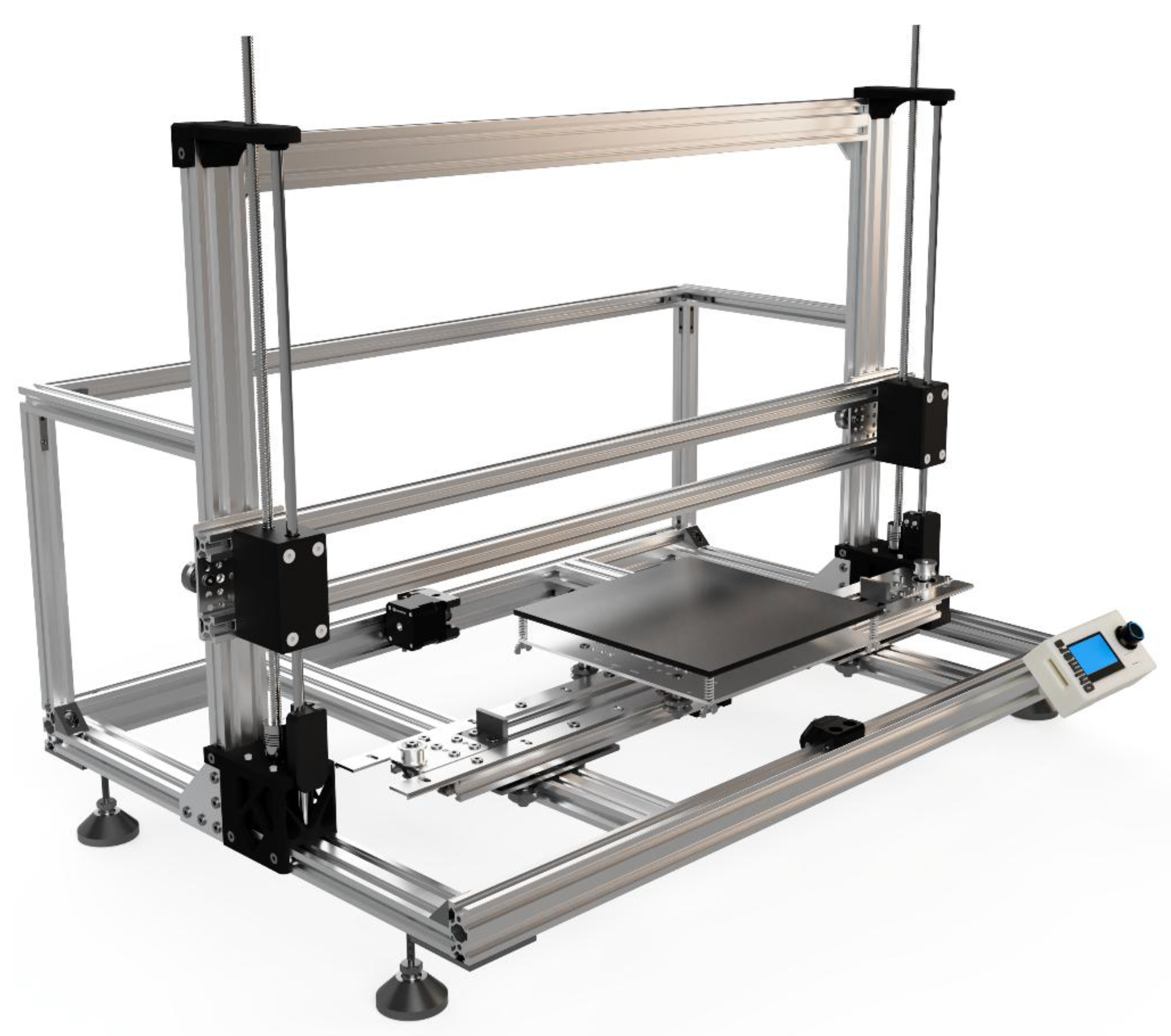
Figure 2.
Extruders designed for the machine: (a) Pneumatic extruder, (b) Plunger extruder, (c) Screw extruder.
Figure 2.
Extruders designed for the machine: (a) Pneumatic extruder, (b) Plunger extruder, (c) Screw extruder.
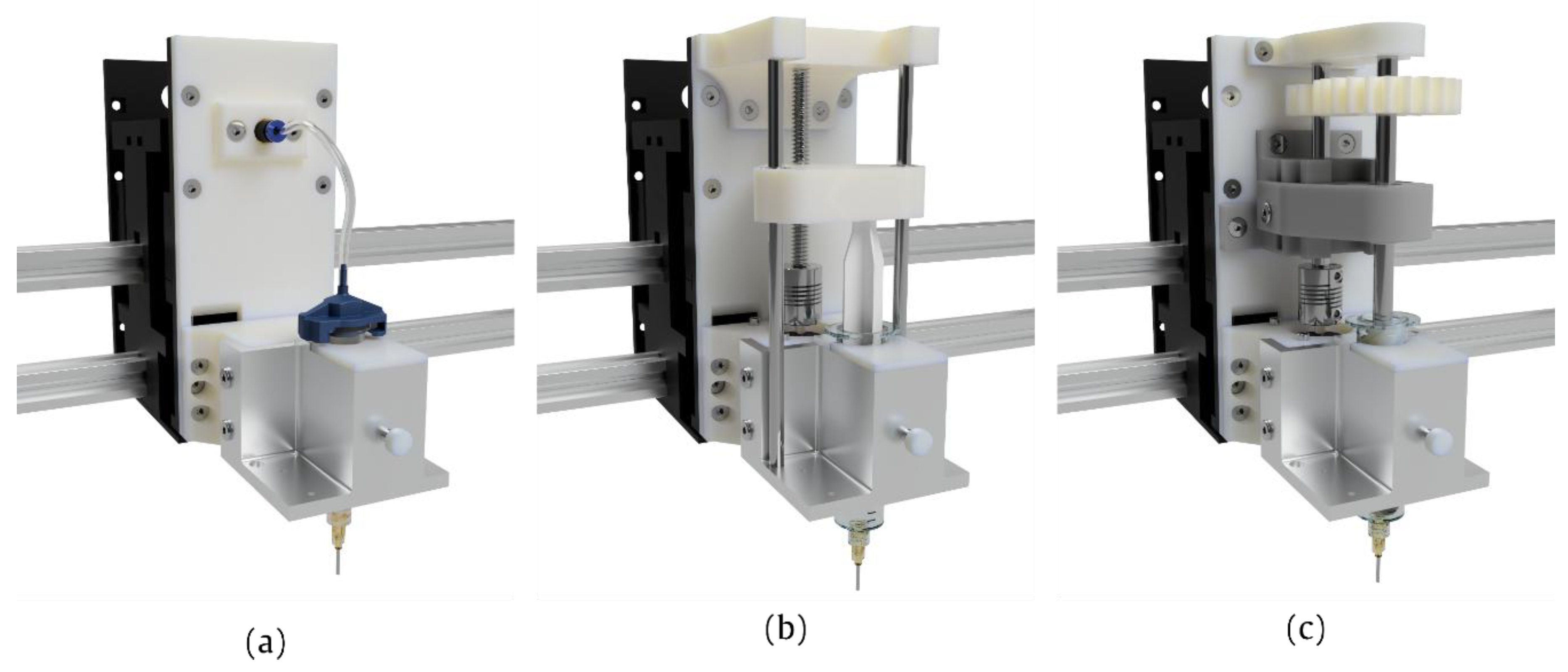
Figure 3.
(a) Surface finish of the screw before (left) and after (right) exposure to acetone vapors; (b) Structure of the screw, drawing.
Figure 3.
(a) Surface finish of the screw before (left) and after (right) exposure to acetone vapors; (b) Structure of the screw, drawing.
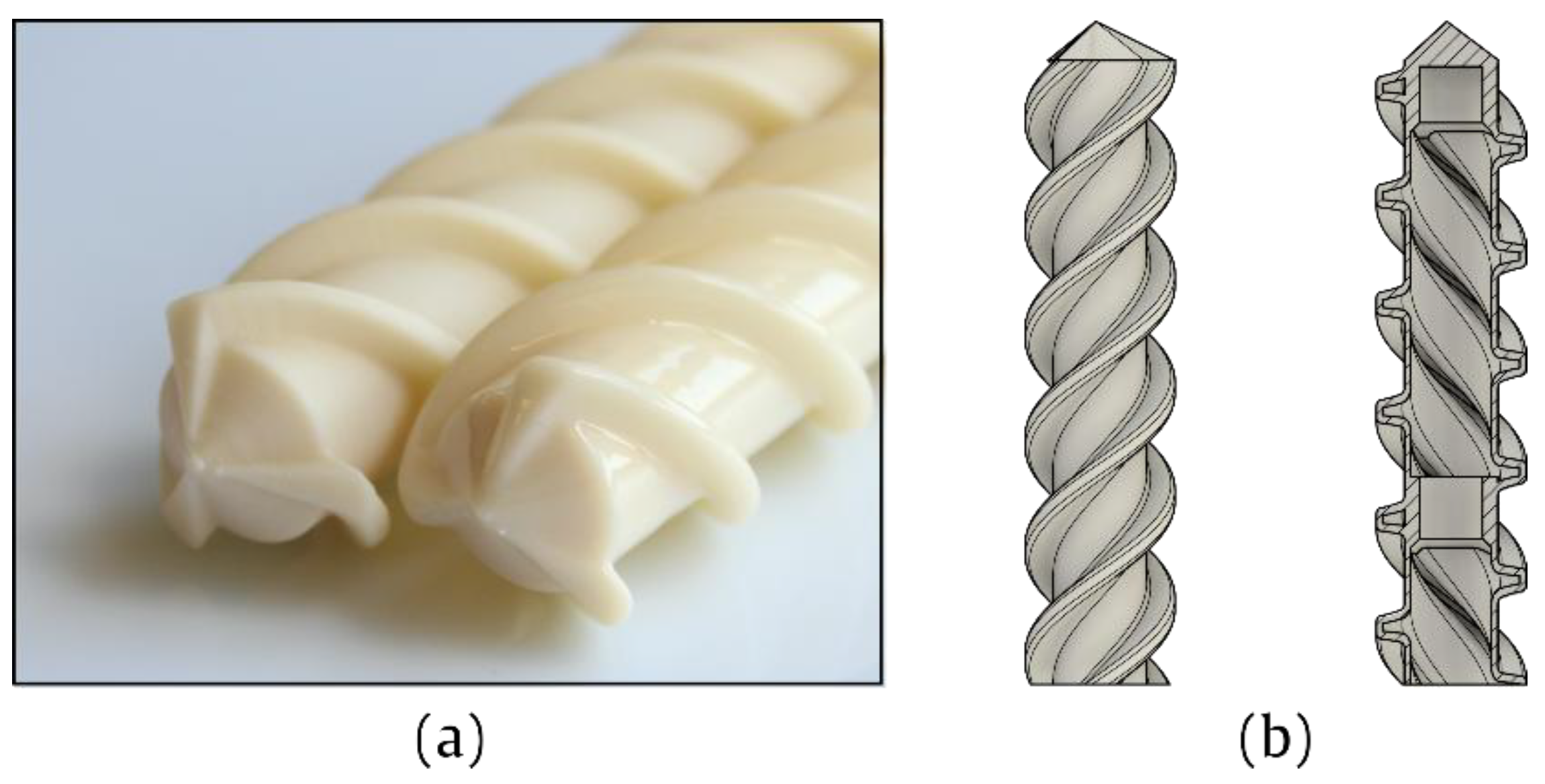
Figure 4.
Theoretical and experimental light intensity profile emitted by the UV curing module, represented (a) in a three-dimensional space and (b) in polar coordinates (highlighted area corresponds to the target surface).
Figure 4.
Theoretical and experimental light intensity profile emitted by the UV curing module, represented (a) in a three-dimensional space and (b) in polar coordinates (highlighted area corresponds to the target surface).
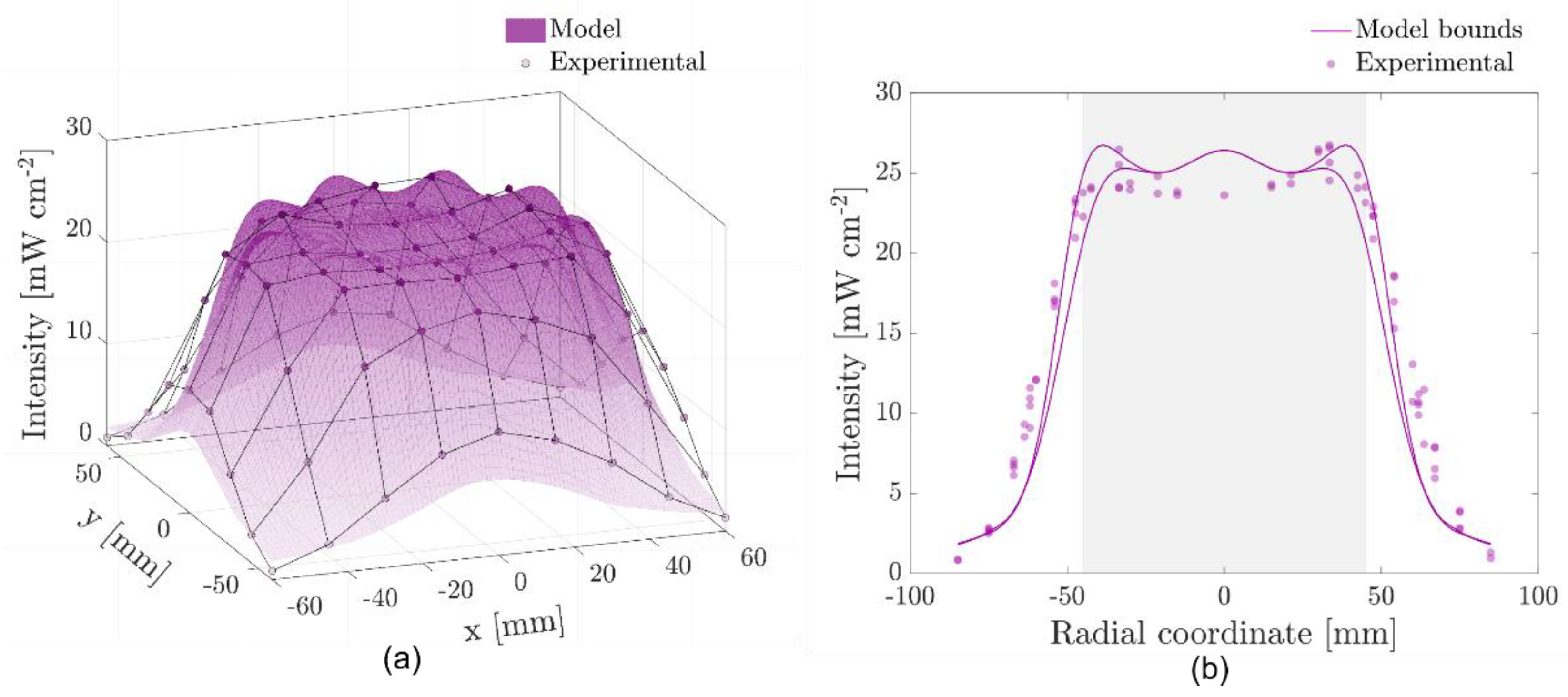
Figure 5.
UV curing unit developed for the platform.
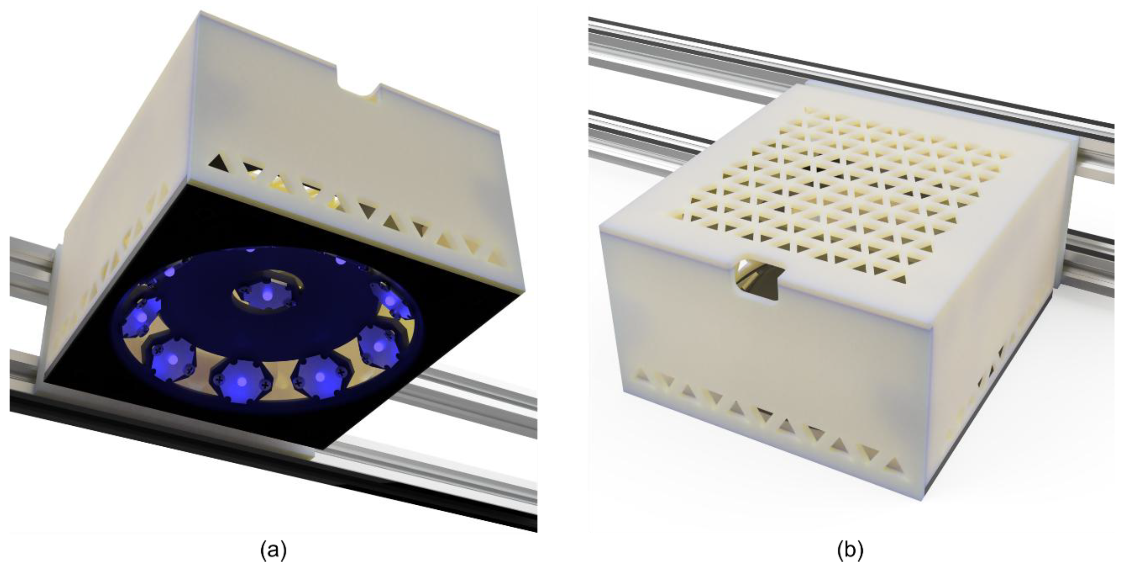
Figure 6.
Graphic user interface from the G-code converter tool.
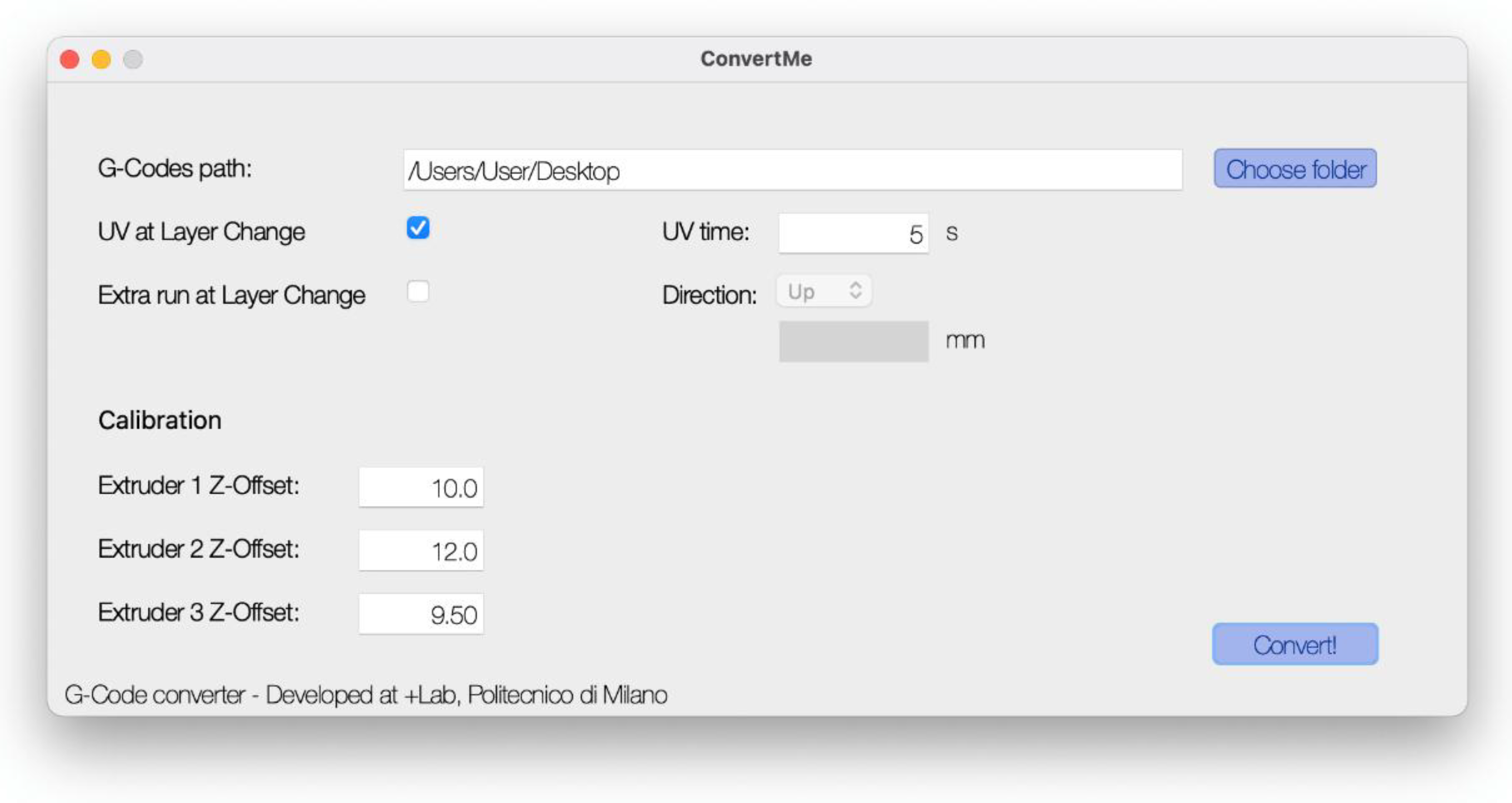
Figure 7.
Single extruder prints made with material 1 and pneumatic (a) or plunger (b) extruder; multi-extruder parts made with the three extruders and material 1 (c, d), material 2 (e) or material 3 (f); single extruder parts made with material 3 and pneumatic extruder (g, h).
Figure 7.
Single extruder prints made with material 1 and pneumatic (a) or plunger (b) extruder; multi-extruder parts made with the three extruders and material 1 (c, d), material 2 (e) or material 3 (f); single extruder parts made with material 3 and pneumatic extruder (g, h).
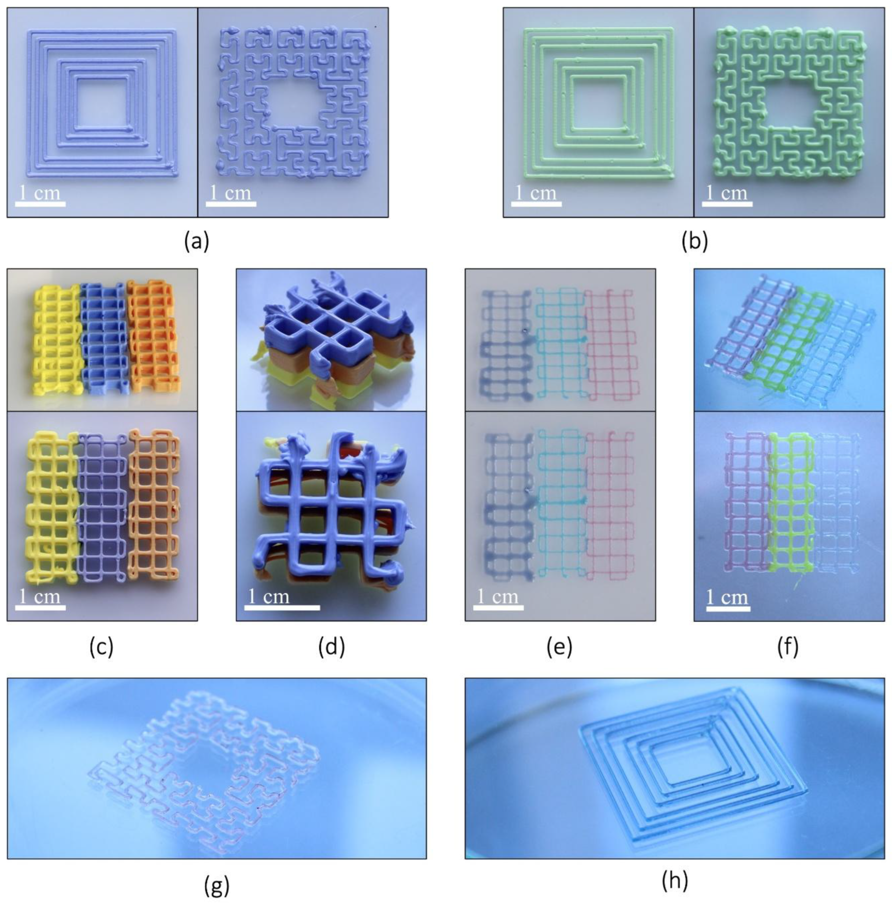

Table 1.
Parameters used for the FFF printing of structural components used in this paper.
| Material | PETG (BioFusion, Extrudr FD3D GmbH) |
| Layer Height | 0.2 mm |
| Nozzle Diameter | 0.4 mm |
| Infill percentage | 30% |
| Infill pattern | Gyroid |
| Number of perimeters | 4 |
| Number of top layers | 4 |
Table 2.
Geometrical variables used for the optimization of LEDs arrangement.
| Variable | Meaning |
|---|---|
| Number of LEDs in the first set (0 or 1) | |
| Number of LEDs on the first ring (integer number) | |
| Number of LEDs on the second ring (integer number) | |
| Vertical distance between the central LED and the target surface | |
| Vertical distance between the center of the first ring and the target surface | |
| Vertical distance between the center of the second ring and the target surface | |
| Radius of the first ring | |
| Radius of the second ring | |
| Inward inclination of the first ring | |
| Inward inclination of the second ring | |
| Rotation angle (with respect to the vertical axis) of the first ring | |
| Rotation angle (with respect to the vertical axis) of the second ring |
Table 3.
Optimized values of the 12 geometrical variables.
| Variable | Value |
|---|---|
| 1 | |
| 9 | |
| 0 | |
| 31 mm | |
| 19 mm | |
| N/A | |
| 50 mm | |
| N/A | |
| 46° | |
| N/A | |
| 100° | |
| N/A |
Disclaimer/Publisher’s Note: The statements, opinions and data contained in all publications are solely those of the individual author(s) and contributor(s) and not of MDPI and/or the editor(s). MDPI and/or the editor(s) disclaim responsibility for any injury to people or property resulting from any ideas, methods, instructions or products referred to in the content. |
© 2025 by the authors. Licensee MDPI, Basel, Switzerland. This article is an open access article distributed under the terms and conditions of the Creative Commons Attribution (CC BY) license (http://creativecommons.org/licenses/by/4.0/).
Copyright: This open access article is published under a Creative Commons CC BY 4.0 license, which permit the free download, distribution, and reuse, provided that the author and preprint are cited in any reuse.


