
Submitted:
02 August 2025
Posted:
04 August 2025
You are already at the latest version
Abstract
Modern production systems increasingly rely on Industry 4.0 technologies, also known as Smart Manufacturing. Among its foundational pillars, additive manufacturing plays a critical role in enabling rapid prototyping and the creation of customised final products with minimal cost and lead time. Key technologies such as Fused Deposition Modelling (FDM), Stereolithography (SLA), and Selective Laser Sintering (SLS) have expanded material capabilities to include plastics, metals, and composites. This study focuses on the implementation of Klipper, an open-source firmware developed to improve 3D printing performance by delegating computational processes to an external microcontroller. A comparative experimental setup was designed using an ordinary printer to evaluate improvements in print speed, dimensional accuracy, and surface quality. The research identifies performance bottlenecks in standard, affordable 3D printers and demonstrates how computer app integration enhances both efficiency and quality. The findings position this kind of computer app as a viable solution for improving the prototyping workflow in cost-sensitive environments, contributing to the broader adoption of advanced manufacturing practices aligned with Industry 4.0 principles.
Keywords:
additive manufacturing
; 3D printing
; Industry 4.0
; open-source software
; fused deposition modeling (FDM)
; performance optimization
; print quality
1. Introduction
Various additive manufacturing techniques have been devised to fulfill the need for producing intricate structures with low waste. The advancement of these technologies has been primarily motivated by the desire for rapid prototyping, mitigating printing imperfections, and enhancing the mechanical characteristics of printed objects. Among these methods, fused deposition modeling (FDM) stands out as the most prevalent form of 3D printing, particularly employing polymer filaments [6,10]. In the FDM process, a continuous thermoplastic polymer filament is utilized to build up material layers three-dimensionally. FDM offers several advantages, including cost-effectiveness, rapid processing, and operational simplicity. Conversely, challenges such as suboptimal mechanical properties, visible layering, surface imperfections, and a limited range of compatible thermoplastic materials are the main drawbacks of this technology [1,9].
Klipper is an open-source 3D printer firmware that integrates processors from single-board computers and 3D printer mainboards into a unified system, enhancing the computational capacity of 3D printers. Traditionally, other 3D printer firmware relied on a single microcontroller to manage file processing and computations to operate the printer’s components. As 3D printer firmware evolves with new features, microcontrollers struggle to cope with the increasing processing demands. Klipper addresses this challenge by distributing processing power across different processors and microprocessors [19].
In conjunction with Klipper, we employed the Mainsail web interface, a user-friendly web-based interface that allows monitoring and control of 3D printers [17]. Users can adjust printer settings, initiate prints, and monitor progress from any device with a web browser, thereby enhancing accessibility and convenience in 3D printing workflows.
1.1. Inputs and Outputs in 3D Printing
1.1.1. What Is FDM 3D Printing
Fused Deposition Modelling (FDM) is the most common type of 3D printing. It works by taking a digital 3D model and a spool of plastic filament as inputs. The printer’s hot end heats the filament, usually at temperatures between 180-260°C depending on the material, bringing it past its glass transition temperature and melting point. This molten material is extruded through a nozzle (with diameters typically ranging from 0.2-0.8mm). It’s then deposited in thin layers (most commonly 0.1-0.3mm thick) onto a build platform, cooling and solidifying to gradually form the final 3D object [1,13,16].
1.1.2. Materials and Properties
FDM printers use a wide variety of thermoplastic filaments. Here’s a look at some common choices and their properties:
- PLA (Polylactic Acid): Easy to print, biodegradable, relatively low melting point (around 180-220°C) and a glass transition temperature between 60-65°C
- ABS (Acrylonitrile Butadiene Styrene): Stronger and more heat-resistant than PLA (with a melting point around 220-260°C and a glass transition temperature of ~105°C), but harder to print
1.1.3. The Print Head and Resolution
The key part of the FDM process is the print head, which includes the nozzle. Nozzles are often made of brass for good heat transfer, or hardened steel for better wear resistance when using abrasive filaments [2,26]. The nozzle diameter, layer height, extrusion width and precision of the printer’s movement all contribute to the final resolution of the printed object [t].
1.2. Our Goals
In this paper, we aim to enhance the overall quality of our specific 3D printer through a process of observation and experimentation, leveraging the built-in tools within the Klipper firmware. Our approach focuses on two goals simultaneously:
- Improving print surface quality and
- Enhancing printing speeds without compromising the quality of our parts.
We will try to demonstrate the impact of utilising the tools provided by Klipper on various aspects of 3D printing, including surface quality and print reliability, and quantify the expected improvements in real-life scenarios. By analysing the outcomes of our experiments, we seek to provide tangible evidence of how the functionalities embedded within Klipper influence both the surface finish and the decrease in print times.
Our methodology begins with a test print of a calibration cube (a reference model in the shape of a 20 x 20 x 20mm cube, which we used to calibrate the printer), to identify potential issues within our 3D printer. Upon identifying a specific problem, we address it using the tools provided by the Klipper firmware and reprint the cube to evaluate the effectiveness of the solution. However, this iterative process often reveals additional challenges that were previously unnoticed.
It is important to note that for the Quality improvements section and Performance improvements section of this paper, filaments from different manufacturers were used, although both PLA, due to the available resources at the time of this research.
Once all discernible part quality issues have been addressed through our iterative problem-solving process, we experiment with increasing the print speeds to assess their impact on real print times, combined with overall higher acceleration values.
2. Hardware-Software Setup
2.1. General Data About a Commercial Printer (Tevo Black Widow)
Tevo Black Widow is a DIY 3D printer kit with a build volume of 370 x 250 x 300 mm [31]. The kit contains a direct drive extruder built out of metal with a 5:1 gear ratio to improve the available torque, and the system is built to be compatible with 1.75 mm filaments. The kit also includes a 400 x 250 heated bed, an MKS MOSFET heating controller, anodized CNC milled plates to help the rigidity of the printer, and an ANTCLABS BLTouch bed probe. All this is controlled through an MKS gen v1.4 board running Marlin software [3].
2.2. The Setup of Our Particular Printer
Reassembled the printer, ensuring everything was aligned and tightened properly, and applied grease to the two Z-axis screws.
Cooling shroud, we have printed and installed a shroud to better direct and focus the airflow through the fins of the hotend, to cool that area more efficiently and remove the risk of heat creep that could aid in printing errors.
Part cooling, the kit doesn’t contain any type of part cooling so we installed a blower-style fan and a simple air duct to better cool our printed parts, as that was a huge bottleneck in printing speeds and quality even from the start.
Belt tensioning mechanism, we printed and installed a screw-based tensioner for the Y-axis belt so we could more easily tighten it.
Glass bed, after finding out our heated bed had a concave shape, we opted for a glass surface, which is flatter and easier to clean, and for the fact that parts come off more easily from the build plate as it cools down.
Klipper firmware, we opted for this open-source firmware because of its features, such as easy and convenient printer tuning and configuration, wifi connectivity, and remote connection to the printer, bringing modern software capabilities to our prints, and offloading the computationally intensive processes to a Raspberry Pi. Our printer can be seen as such in Figure 1 in its current setup.
3. Quality and Speed Improvements
3.1. Quality Improvements
3.1.1. Measuring and Visualising the Flatness of the Bed
Using the “Heightmap” feature, we can take multiple probes on the surface and visualise it as a mesh. Klipper also stores the highest and lowest points and gives us an approximate difference between the peaks that the bed probe reads. The mesh was created by a 6 x 6 grid of points equally spaced on the print bed [3]. In Figure 2 and Figure 3, it can see the mainsail web interface in the “Heightmap” panel, from here, we can start the calibration procedure to create a bed mesh, we can home the printer, and we can also load saved bed meshes to visualise [17]. Every loaded bed mesh has a NAME, a grid size (in our case 6x6), the maximum and minimum values recorded in reference to the origin point (in our case placed in the dead centre of the print bed) in mm and the range being the difference between the minimum and maximum recorded values. In this panel, you can also toggle on or off and visualise the flat plane to better see the shape and height difference of the bed in reference to the origin point, the wireframe and the calculated mesh.
The stock heated bed can be seen in Figure 2 as being concave, with the highest point at 0.364 mm, the lowest point at -0.214 mm a delta of 0.578 mm. In Figure 3, we can see the mesh of the glass surface, which is way flatter, which is also confirmed by the software, where we can see it has the highest point at 0.179 mm, the lowest point at -0.129 mm, and a lower than before delta of 0.308 mm and a generally flatter mesh.
3.2. What Is PID Tuning and How It Works
First, we printed a calibration cube, and we identified that there appeared to be in-consistent layer heights, and after verifying the Z screws were moving freely and without a problem, we identified the first limitation in our printer’s performance, the fluctuating temperatures, so we used the PID tuning feature of Klipper to solve this issue [12,15].
PID controller stands for Proportional Integral Derivative Controller and in our case, it’s a digital temperature controller application, and its job is to take and maintain a steady state for a particular function. It’s a closed-loop feedback system that continuously measures the error in your system and tries to correct it [7,18,20].
An error like the one seen in Figure 4, where the temperatures fluctuate above and below the target.
After running the
PID_CALIBRATE HEATER=heater_bed TARGET=60
and
SET_HEATER_TEMPERATURE HEATER=extruder TARGET=210
commands in the console, as 210°C for the extruder and 60°C for the bed are the temperatures we’re usually printing at, the software runs a heat cycle routine (seen in Figure 5) for the heated bed and the extruder that will generate the PID values and correct the fluctuations seen before while trying to hold a steady temperature [4].
After saving the generated values using the printer’s configuration commands, we tested to see if it maintained a steady temperature — and it did. As that wasn’t enough proof, we printed another calibration cube after the changes to see if there is any visible quality improvement.
The tuning completely eliminated the horizontal rings that appeared on the cube on the left, as shown in Figure 6; however, it also made another printing error more noticeable. The repeated horizontal patterns and lines are known as ringing or ghosting. That 3D printing quality issue results from vibration in layers, too high a printing speed, high acceleration, or a displacement in the printing area.
3.3. Input Shapers and Mechanical Vibrations
As mentioned, the Klipper application is a firmware designed to compensate for vibrations in 3D printers. In theory, a number of shapers (motion shape filters) have been established over time and are also used in Klipper [27,28,29,30]. These are:
- ZV (Zero Vibration) is the simplest input shaper, consisting of two equal impulses. It is designed to cancel a single resonance frequency and introduces minimal delay. However, it offers limited vibration suppression and is sensitive to errors in the estimated frequency. Is a shaper with fast execution and minimal latency but sensitive to model inaccuracies.
- MZV (Modified Zero Vibration) improves on ZV by adding a third impulse, enhancing robustness and reducing residual vibration. It handles small errors in resonance estimation better but introduces slightly more delay. MZV has better suppression and modest robustness but is still sensitive to frequency drift. MZV is recommended for general-purpose compensation.
- EI (Extra Insensitive) is designed to be less sensitive to inaccuracies in resonance frequency detection. It balances vibration suppression and robustness better than ZV or MZV. It is moderately complex, with a longer impulse duration. EI is robust to resonance drift, good overall performance but has slightly higher delay. EI is suitable for systems with changing or uncertain resonances
- 2HUMP_EI extends EI by using additional impulses, allowing better suppression of both primary and harmonic frequencies. It is highly robust and reduces ghosting in prints but introduces notable execution delay. 2HUMP_EI has great suppression and improved print surface quality, but offers a slower response. 2HUMP_EI is ideal for printers with strong structural resonance and visible ghosting.
- 3HUMP_EI is the most advanced of the EI family. 3HUMP_EI uses even more impulses to flatten vibration over a wider frequency range. It achieves excellent ghosting suppression at the cost of the highest delay. It offers best overall suppression and extremely smooth prints but high latency and may limit speed or require tuning acceleration. Is best for high-speed or coreXY printers with demanding accuracy requirements.
Table 1 summarises the main characteristics of input shapers used in Klipper firmware for 3D printing vibration compensation in the case of low-speed printers or where response time is critical. This comparative table is based on official documentation, source code, scientific literature, and community experience [35,36,37,38].
3.4. Comparative Analysis
Input shaper is a feature supported by Klipper. It’s an open-loop control technique that creates a commanding signal that cancels the printer’s vibrations. One of the most accurate ways to tune the values for your device is by measuring the resonance using an accelerometer [24].
We connected an MPU6050 gyroscope and accelerometer to our Raspberry Pi and ran two tests in Klipper using the command TEST_RESONANCES. Once for the X-axis, and once for the Y-axis, which returned 2 CSV files that we plotted onto graphs, using a stand-alone script on the Raspberry Pi.
We have generated two graphs that show us the frequency response of our different axis. Figure 7 and Figure 8 show the frequency response and efficiency of different shapers (motion shape filters) in reducing mechanical vibrations on the X (Figure 7) and Y (Figure 8) axes of the 3D printer, respectively. It is a specific result generated by Input Shaping, using the Klipper firmware.
Left Y axis (Power spectral density) represents the vibration energy (the higher, the more vibration), the colored curves X, Y, Z show the spectral distribution of vibrations on each axis and the thick black curve (“After shaper”) shows the vibrations after applying a shaper – that is, how well the vibrations were reduced.
Right Y axis (Shaper vibration reduction ratio) displays the efficiency of each shaper (filter) in reducing vibration at certain frequencies.
X axis (Frequency, Hz) represents the frequencies at which vibrations occur (printer resonances). Peaks usually indicate points where vibration is strong (natural mechanical resonance).
These graphs can be simplified as weights on a spring(ex: printhead moved by a belt that’s elastic in nature or print bed moved by a belt), and in a perfect system with a perfectly rigid frame we would only see a single peak in our graphs, representing the resonance frequency of the weight of the respective axis on it’s belt, for example, in our case we can observe that for both axis we can see a primary peak that indicates the resonance frequency of the weight moved by the belt, a secondary peak at around 40Hz in BOTH graphs that would suggest that to be the resonance frequency of our printer’s frame as it’s not perfectly rigid, as well as smaller peaks at 70-75Hz in Figure 7 and 105-110Hz in Figure 8 that could point to too lose or too tight belts, lose screws, friction in the movement of the axis or just improper or not solid enough mounting of the gyroscope to the axis at the moment of the testing.
These graphs contain a lot of information, of which (we can see in the top right) the most important would be the Klipper input shapers ZV, MZV, 2hump_ei, 3hump_ei, EI represented by their respective dotted lines, the recommended shaper that will reduce vibrations the most, “sm” or smooth time, and “accel” or acceleration which is the maximum recommended acceleration for that axis. After looking at both graphs, we chose a middle-ground option.
Usually, for bed-slinger printers, it’s recommended to choose the lowest out of the two axis recommended accelerations, in our case being the Y-axis with the “EI” shaper at an accel of 1900 mm/s2, but we were more concerned with striking a balance between speed and quality so we upped the acceleration to 2500 mm/s2.
Besides those it’s important to mention the rest of information we get, in the top left we can the the resonance response of every axis of the gyroscope (x, y and z respectively), the purple line is the combination of all the axis into one, and the cyan line is the expected frequency response of the system after applying the recomended input shaper,
This acceleration value (2500 mm/s2) is significantly higher than the stock setting of 1000mm/s2 , but acceleration alone doesn’t make a big difference in print times. Input Shaper, through the way it works, allows us to use higher print speeds in our slicer without accentuating the ghosting effect. (Figure 9).
3.4. Pressure Advance
The pressure advance feature can help reduce ooze. In the ideal case, as an extrusion move progresses, the same volume of filament should be deposited at each point along the move. It’s common while following basic extrusion formulas to cause too little material to exit the extruder at the start of an extrusion move, and too much material to exit after the extrusion ends [21].
The “pressure advance” system attempts to account for this by using a different model for the extruder. Instead of assuming that the volume of plastic fed into the extruder will immediately exit it, like in the trapezoidal move in Figure 10, Klipper uses a model based on pressure. (as shown in the “actual filament” in Figure 10) The key idea is that the relationship between filament, pressure, and flow rate can be modelled using a linear coefficient:
pa_position = nominal_position + pressure_advance_coefficient * nominal_velocity
The basic pressure advance formula can cause the extruder motor to make sudden velocity changes. Klipper implements “smoothing” of the extruder movement to avoid this [14].
The graph in Figure 11 shows an example of two extrusion moves with a non-zero cornering velocity between them.
The pressure advance system causes additional filament to be pushed into the extruder during acceleration [13]. The higher the desired flow rate, the more filament will be pushed in during acceleration to account for pressure. During the deceleration, the extra filament is retracted (the extruder will have a negative velocity).
To calibrate pressure advance, the printer must be configured and operational, as the tuning test involves printing and inspecting a test object. We used a slicer to generate the G - code for a large hollow square, with zero infill, a layer height of 75% of the nozzle diameter (nozzle of 0.4 mm), and a print speed of 100mm/s. Then we used the
SET_VELOCITY_LIMIT SQUARE_CORNER_VELOCITY=1 ACCEL=500
and
TUNING_TOWER COMMAND=SET_PRESSURE_ADVANCE PARAMETER=ADVANCE START=0 FACTOR=.005
commands and started the print.
The “TUNING_TOWER” command instructs Klipper to alter the pressure_advance setting on each layer of the print. Higher layers in the print will have a larger pressure advance value set, and “SET_VELOCITY_LIMIT” makes the nozzle travel slower through corners to emphasize the effects of extruder pressure.
With this emphasis on the extruder pressure, we expect to see the corners to change with every layer (Figure 12), going from rounded (from too much filament leaving the nozzle) to sharp to finally underextruded corners from too high of a pressure advance value that retracts too much filament [13,16].
After about half an hour we observed on the tower that the area with the sharpest corner already passed, and on the higher layer there were signs of under-extrusion, so we stopped the print (Figure 13). We measured the height of the best corner at about 13.50 mm distance from the base and marked it, and using the given formula of pressure_advance = <start> + <measured_height> * <factor>, we got a value of 0+13.50*0.005= 0.0675, which we saved into the printer config file.
4. Performance Improvements
4.1. Theoretical Limits
If we’re talking about our maximum print speed, we’re limited by two big factors: how much filament can we push through the nozzle and how fast can we cool it afterward? As our cooling fan is working at 100% capacity during our prints, we can’t gain any benefits without finding a better cooling solution like a bigger fan, a larger quantity of fans, or a more efficient cooling duct.
After doing some extrusions of 20mm of filament at different feed rates, we observed our hotend is capable of a volumetric flow of 12 mm³/s at an extrusion feed rate of 5mm/s on the 0.4mm nozzle we have installed. We know that volumetric flow = speed * line width * layer height [5,23]. With this formula, we can determine that our theoretical maximum print speed is 150 mm/s with a 0.4 nozzle and a 0.2 layer height.
4.2. Real-World Performance Improvements
For our testing, we printed 3 models, with all the quality improvements and higher printing speed, and compared them to how they used to be printed before all the changes and calibrations. We chose a calibration cube [32], because it’s small, and doesn’t have many features, making it easier to inspect the surface quality, and a speaker ring [26], because it’s round and combines both the X and Y-axis in its moves at the same time. Furthermore, for our third model, we chose an articulated dragon [33], because it’s a more complex and organic shape that should benefit from both higher accelerations and faster printing speed settings in the slicer, while also showcasing printing errors.
For our slicing, we used Ultimaker Cura 5.5.0 slicer since it’s a commonly used slicer [16]. For our settings, we added the Tevo Black Widow printer as a profile, and for our default prints, we used the Draft 0.3 mm layer height, or Normal 0.2 mm layer height profiles without any changes.
For this section of real-world improvements and testing, we used CR-PLA Fluo-Red filament from Creality, with a nozzle temperature of 210°C and a bed temperature of 60°C.
In the following section, we will describe the details of the printing process and the time improvements achieved. Any changes that we made to the slicer settings or particularity will be mentioned for each model.
4.2.1. Calibration Cube
For our “fast” print
Settings: Normal 0.2 mm profile - 0.4 mm nozzle
- Print speed: 100 mm/s
- Generate support: no
- Build plate adhesion: brim
- Ironing: enabled
Figure 14.
Calibration Cube 50mm/s (left) next to Calibration Cube 100mm/s (right).
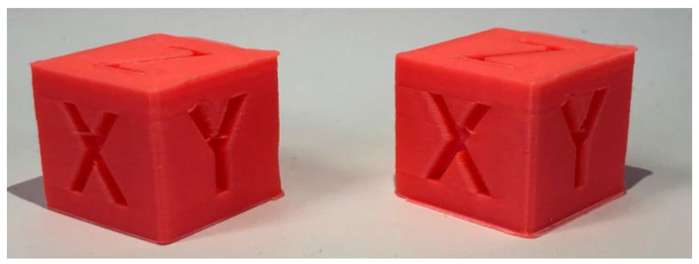
For our “slow” print we used the same settings, only with the print speed being 50mm/s. The “fast” print finished in 23m 2s with an average of 13.9s per layer, compared to the “slow” 30m 38s with an average of 18.5s per layer, giving us an approximate 33% improvement.
4.2.2. Speaker Ring
For our “fast” print
Settings: Normal 0.2 mm profile - 0.4 mm nozzle
- Print speed: 100mm/s
- Generate support: yes
- Build plate adhesion: brim
- Infill: gyroid
- Ironing: enabled
Figure 15.
Speaker Ring 50mm/s (left) next to Speaker ring 100mm/s (right).
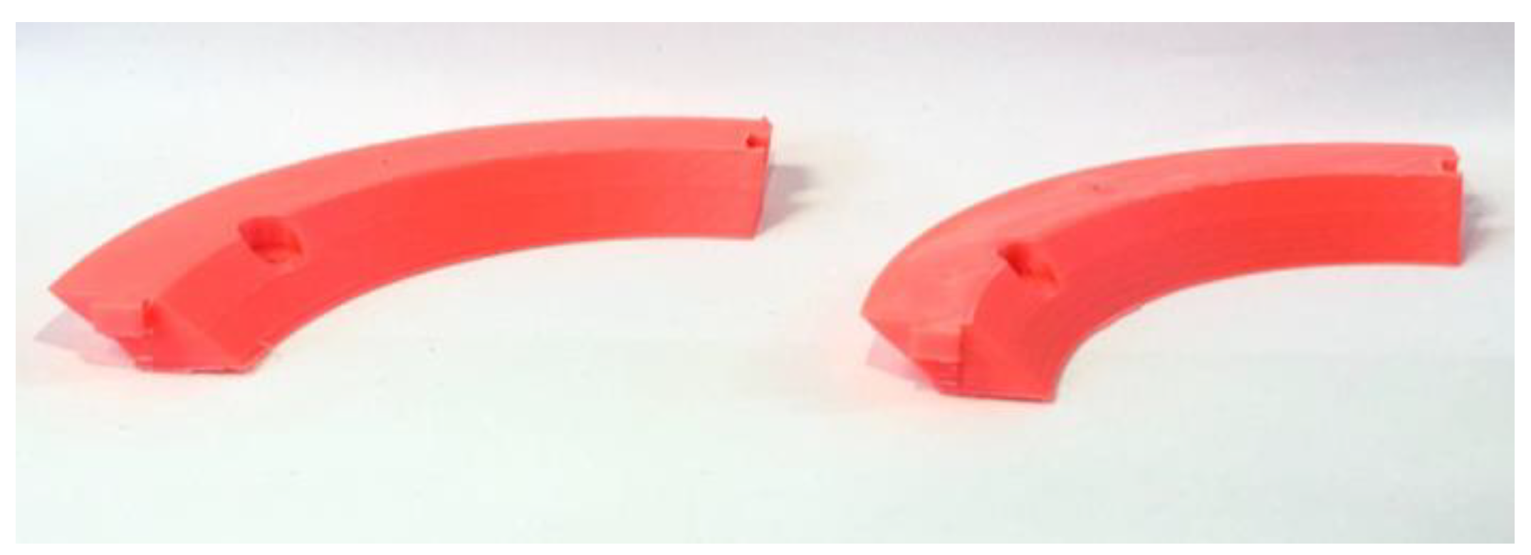
The “slow” profile was the same, only with the print speed being 50mm/s. Our print time went from 3h 17m 57s to 1h 49m 33s, or from an average of 3m 15s per layer to an average of 1m 46s per layer, with an approximate improvement of 55%.
4.2.3. A Complex 3D Object (Articulated Dragon)
For our “fast” print
Settings: Normal 0.2 mm profile - 0.4 mm nozzle
- Print speed: 100 mm/s
- Generate support: yes
- Build plate adhesion: brim
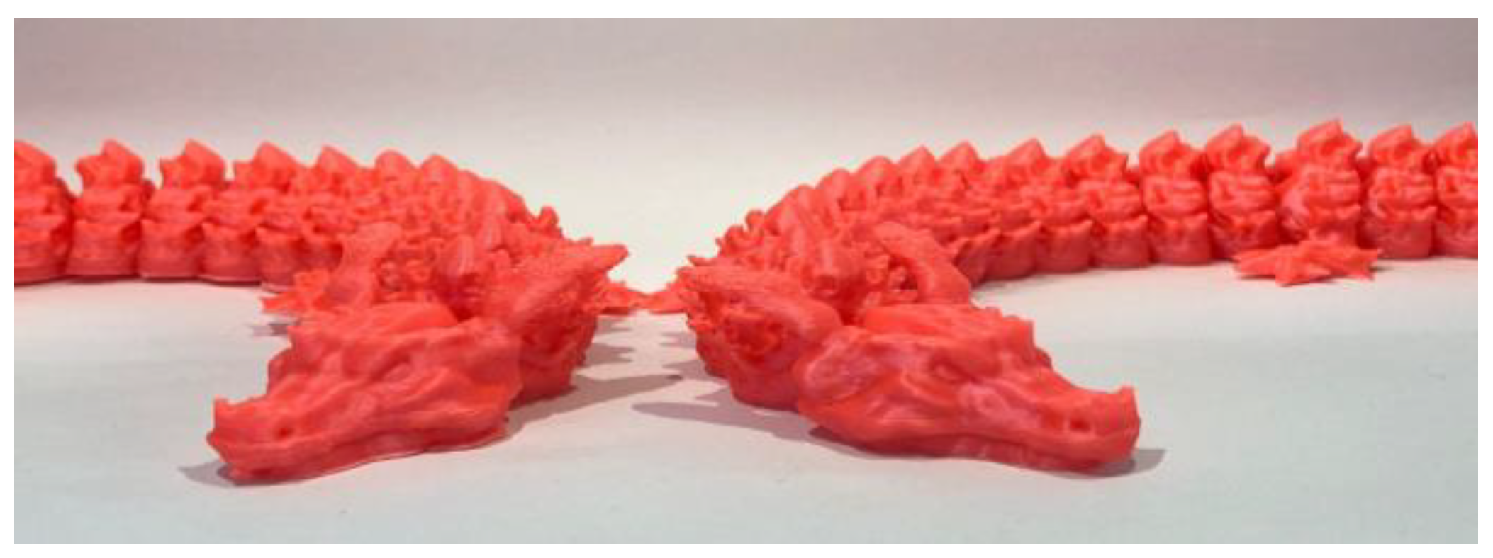
The “slow” profile was the same, only with the print speed being 50mm/s. Our print time went from 12h 15m 2s to 7h 54m 13s, or from an average of 5m 52s per layer to an average of 3m 47s per layer, with an approximate improvement of 55% in print time.
4.3. Limitations of Our Testing
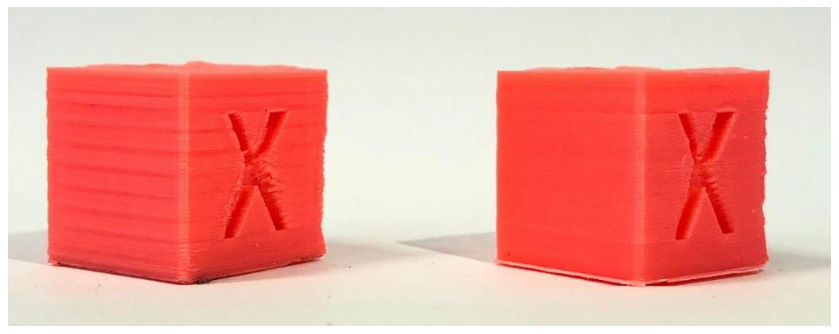
Overall, we improved the surface finish while also improving the printing time by an average of 47.6%. We have improved the quality of our prints going from parts with a lot of surface quality issues to prints with barely any major defects while also reducing the print times to around half on average, this being best shown in Figure 17, overall achieving our set goal of improving one without sacrificing the other, thanks to Klipper and it’s tools.
Figure 16.
Articulated dragon 50mm/s (left) next to articulated dragon 100mm/s (right).
It is also important to notice that the time improvement of the Calibration Cube was only improved by 33%, compared to the other two objects that we printed. This could be the direct result of a slicer setting called “minimum layer time” which limits or slows down the print speed so a layer takes at least a specified ammount of time so it can cool down and not warp or melt, especially important for models with a small volume that are printed fast, where usually layers take a very small amount of time to finish, this could be improved by a better part cooling solution that would allow us to modify the “minimum layer time” setting in our slicer to a smaller value.
Figure 17.
Calibration cube printed 50mm/s before all improvements (left), next to calibration cube printed at 100mm/s after all improvements are applied.
Figure 17.
Calibration cube printed 50mm/s before all improvements (left), next to calibration cube printed at 100mm/s after all improvements are applied.
In our research we didn’t:
- Try more nozzle sizes and types, we stuck with only 0.4 mm nozzles
- Try more materials besides PLA and see if the performance is any different with other common materials like PETG or ABS
- Try PLA from a multitude of manufacturers, as it could have an impact on maximum print speed or printing times
- Try multiple printer configurations like Core XY or Delta printers, we only tested on a bed slinger type of printer
- Try different slicer options or settings to print faster or better quality parts
- Try different extruder hotends that could melt plastic better or worse than ours
All of these factors could and most probably make a difference in the quality of parts as well as in how fast you can print, the results of the “Quality improvements” steps like Input Shaper or Pressure Advance would be different from our own, based on the specific setup of the printer or material used.
5. Conclusions
At the start, our 3D printer struggled with numerous defects that flawed the final prints. Print quality was inconsistent, and really slow with numerous visual defects. These challenges made it clear that a complete revision of the printer’s firmware and calibration was necessary
This project demonstrated that switching to Klipper firmware can be a game-changer for 3D printing. After carefully setting up Klipper and dialling in calibrations like PID tuning, Input shaper, and Pressure advance and boosting the print speed from 50mm/s to 100mm/s, substantial improvements in print speed (up to 55%) were achieved without compromising part quality.
Both Calibration cubes (Figure 14) measured 20x20x20mm when inspected with calipers, showing that we kept the same dimensional accuracy, the speaker rings (Figure 15) have slotted into one another, creating perfect a circle, showing no signs of warping and that we didn’t introduce any error while printing them faster, and the complex shape of the articulated dragon (Figure 16) highlighted that we can also maintain the same level of surface quality without sacrificing speed.
These improvements highlight why Klipper is increasingly becoming the default firmware choice for production machines. Its potential to boost industrial processes and applications is significant. Additionally, further research into advanced Klipper configuration options could lead to even greater print speed and quality refinements. Klipper, as an open-source firmware and robust firmware option, has huge value in expanding the capabilities of 3D printing technology and benefiting small-scale manufacturing and rapid prototyping.
PDF processing through Rapid Prototyping is not only designed for the production of toys or consumer goods. 3D printing, also known as additive manufacturing, plays a key role in the digital transformation of production characteristic of the Industry 4.0 paradigm, being one of its 9 pillars. This technology allows the rapid and flexible production of complex components, directly from digital models, eliminating the need for traditional tools or molds. Thus, it reduces production costs, time to market and material waste, contributing to the sustainability of industrial processes.
In the context of Industry 4.0, 3D printing is integrated with technologies such as Industrial Internet of Things (IIoT), Simulation and Optimization, Virtual Reality and artificial intelligence (AI), thus making the transition to Industry 5.0, with the aim of creating smart factories. It allows mass customization, “on-demand” production and adaptability of supply chains. In this sense, the need for high precision and high printing speed becomes essential for ensuring product quality, especially in critical areas such as aerospace, medical or automotive industries. Achieving this goal responds to the rapid demand in modern industry and supports continuous flow production.
In engineering and prototyping, 3D printing accelerates product development and stimulates innovation. In combination with digital twins and simulation, 3D printing becomes a key link in the Industry 4.0 ecosystem, supporting the transition to a more precise, fast and digitalized industry.
References
- Abbasi, M.; Váz, P.; Silva, J.; Martins, P. Head-to-Head Evaluation of FDM and SLA in Additive Manufacturing: Performance, Cost, and Environmental Perspectives. Appl. Sci. 2025, 15, 2245. [Google Scholar] [CrossRef]
- Ahmad, M.N.; Ishak, M.R.; Mohammad Taha, M.; Mustapha, F.; Leman, Z. A Review of Natural Fibre-Based Filaments for 3D Printing: Filament Fabrication and Characterisation. Materials 2023, 16, 4052. [Google Scholar] [CrossRef] [PubMed]
- Bed Mesh. Klipper 3D Printer Firmware. Available online: https://www.klipper3d.org/Bed_Mesh.html (accessed on January 13, 2024).
- Configuration checks. Klipper 3D Printer Firmware. Available online: https://www.klipper3d.org/Config_checks.html (accessed on January 14, 2024).
- Determining maximum Volumetric Flow Rate. Available online: https://ellis3dp.com/Print-Tuning-Guide/articles/determining_max_volumetric_flow_rate (accessed on 14.01.2024).
- Doicin, C.V.; Ulmeanu, M.E. Quantitative Network Design Analysis in a Multimodal Transportation Company Serving the Additive Manufacturing Industry, U.P.B. Sci. Bull. Bull, 2025. [Google Scholar]
- Ghinea, M.; Agud, M.; Bodog, M.; Agud, M.A. Pneumatic cylinders controlled by two different controllers, Arduino and MyRIO: An educational approach, International Journal of Education and Information Technologies, 2022, 15, 110-120.
- Glass Transition Temperatures of PLA & PETG available on: https://all3dp.com/2/pla-petg-glass-transition-temperature-3d-printing/ (accessed on , 2025). 11 January.
- Hui, D.; Imbalzano, G.; Kashani, A.; Ngo, T. D.; Nguyen, K. T. Q. Additive manufacturing (3D printing): A review of materials, methods, applications and challenges. In Composites Part B: Engineering, Editor Hui, D., Feo L.; Publisher: Elsevier, Amsterdam, The Netherlands, 2023. [Google Scholar]
- Iacob, M.C.; Popescu, D.; Alexandru, T.G. Printability of Thermoplastic Polyurethane with Low Shore Hardness in the Context of Customised Insoles Production, U.P.B. Sci. 2024. [Google Scholar]
- Input shaper tuning examples and field data. Available online: https://www.reddit.com/r/klippers (accessed on July 23, 2025).
- Ismail, L.S.; lupu, C.; Alshareefi, H.; Luu, D.L. Design of PID Controller for Nonlinear Magnetic Levitation System Using Fuzzy-Tuning Approach, U.P.B. Sci. Bull., Series C, 2022, 84(2), 45-62. 84(2).
- Kantaros, A.; Soulis, E.; Petrescu, F.I.T.; Ganetsos, T. Advanced Composite Materials Utilised in FDM/FFF 3D Printing Manufacturing Processes: The Case of Filled Filaments. Materials 2023, 16, 6210. [Google Scholar] [CrossRef] [PubMed]
- Kinematics. Klipper 3D Printer Firmware. Available online: https://www.klipper3d.org/Kinematics.html (accessed on January 16, 2024).
- Klipper PID Tuning - How To Guide. Available online: https://www.obico.io/blog/klipper-pid-tuning/, (accessed on April 8, 2024).
- Kristiawan, R.B.; Imaduddin, F.A.; Dody, U.; Arifin, Z. A review on the fused deposition modeling (FDM) 3D printing: Filament processing, materials, and printing parameters, Open Engineering, 2021, 11(1), 639-649.
- MainSail web interface for Klipper. Available online: https://docs.mainsail.xyz (accessed on day month year).
- Mhatre, S.; Nair, R.; Thakare, O.; Gund, A.M. Implementation Of PID Controller Using Arduino Microcontroller. IJSART.
- Nguyen, A. Hard Real-time Linux on a Raspberry Pi for 3D Printing. Master’s thesis, San Jose State University, 2022.
- PID controller implementation using Arduino. Microcontrollerslab. Available on: https://microcontrollerslab.com/pid-controller-implementation-using-arduino/ (accessed on , 2024). 13 January.
- Pressure Advance. Klipper 3D Printer Firmware. Available online: https://www.klipper3d.org/Pressure_Advance.html (accessed on January 15, 2024).
- Resonance Compensation - Klipper Documentation. Available online: https://www.klipper3d.org/Resonance_Compensation.html (accessed on July 23, 2025).
- Resonance.py – Input shaper definitions. Available online: https://github.com/Klipper3d/klipper/blob/master/klippy/extras/resonance.py. (accessed on July 23, 2025).
- Resonance Compensation. Klipper 3D Printer Firmware. Available online: https://www.klipper3d.org/Resonance_Compensation.html (accessed on January 14, 2024).
- Reverson, F.Q.; Domingos da Silveira, G.; Francassi da Silva, J.A.; Pereida de Jesus, D. Understanding and improving FDM 3D printing to fabricate high-resolution and optically transparent microfluidic devices. Lab on a Chip. 2021, 19. [Google Scholar]
- Speaker Adapter Ring 5.25 to 6.5 inch [3D Model]. Available online: https://www.thingiverse.com/thing:3467433. (accessed on March 30, 2025).
- Saikat, C.; Shankar, C. A multi-criteria decision-making approach for 3D printer nozzle material selection. Reports in Mechanical Engineering,.
- Singh, T. R.; Seering, W. P. Preshaping Command Inputs to Reduce System Vibration, Journal of Dynamic Systems, Measurement, and Control, 1990b, 112(1), 76–82.
- Singh, T.; Vadali, J. Robust Time-Delay Control, Journal of Dynamic Systems, Measurement, and Control, 1993, 115(2B), 303–310.
- Singh, T.; Huang, T. Optimal Multiple-Mode Input Shapers, Journal of Dynamic Systems, Measurement, and Control, 1996, 118(4), 781–786.
- Tevo Black Widow 3D Printer Kit V3. Available online: https://www.3dprintersbay.com/tevo-black-widow-3d-printer (accessed on 20.01.2023).
- Thingiverse - XYZ 20mm Calibration Cube [3D Model]. Available online: https://www.thingiverse.com/thing:1278865. (accessed on 18.05.2024).
- Thingiverse - articulated flame dragon [3D Model]. Available online https://www.thingiverse.com/thing:5337105. (accessed on 11.04.2024). (accessed on 11.04.2024).
- The Best ABS Print & Bed Temperature Settings available on: https://all3dp.com/2/abs-print-bed-temperature-all-you-need-to-know/#i-5-hot-end, (accessed on , 2024). 21 November.
- Vaughan, J.; Singh, T.; Chow, M. Enhancing the robustness of time-delay control, in Proceedings of the American Control Conference (ACC), Portland, OR, USA, 2005.
- Vaughan, J.; Singh, T. Robust time-delay filters for flexible systems, Journal of Dynamic Systems, Measurement, and Control, 2004, 126(2), 255–261.
- Wei, X.; Zhang, S.; Sun, L.; Zhao, X.; Sun, M.; Yu, R.; Zhou, X.; Li, Y. Geometric Accuracy and Dimensional Precision in 3D Printing-Based Gear Manufacturing: A Study on Interchangeability and Forming Precision. Polymers 2025, 17(3), 416. [Google Scholar] [CrossRef] [PubMed]
- Zhow, P.; Qi, F.; Hu, Y.; Chen, L.; Chen, Y. Numerical Simulation of Factors Affecting the Weight Distribution Uniformity of Vibrating through Materials, U.P.B. Sci. 2024. [Google Scholar]
Figure 1.
The Tewo Black Widow printer - the “guinea pig” of our research.
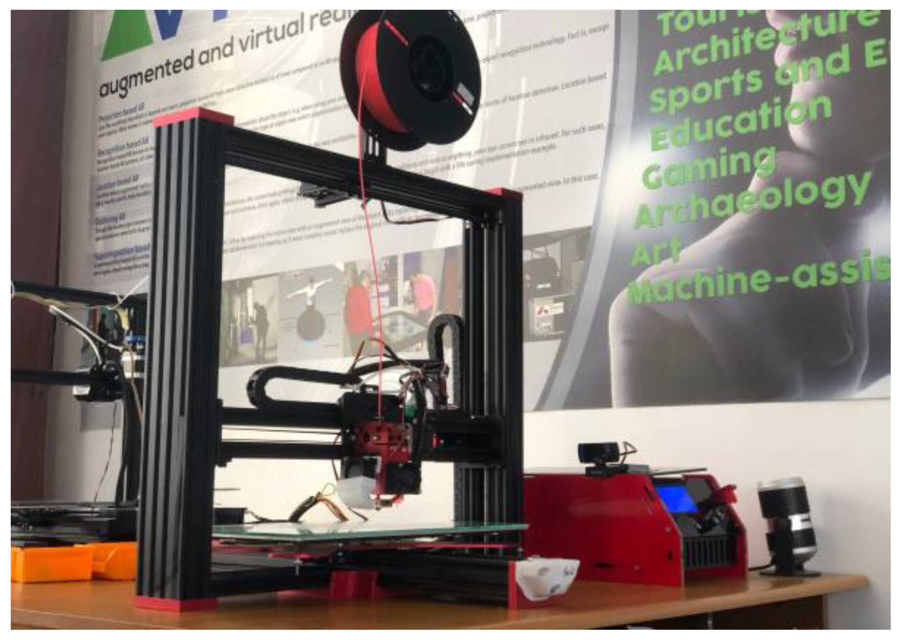
Figure 2.
Bed mesh of our initial print bed.
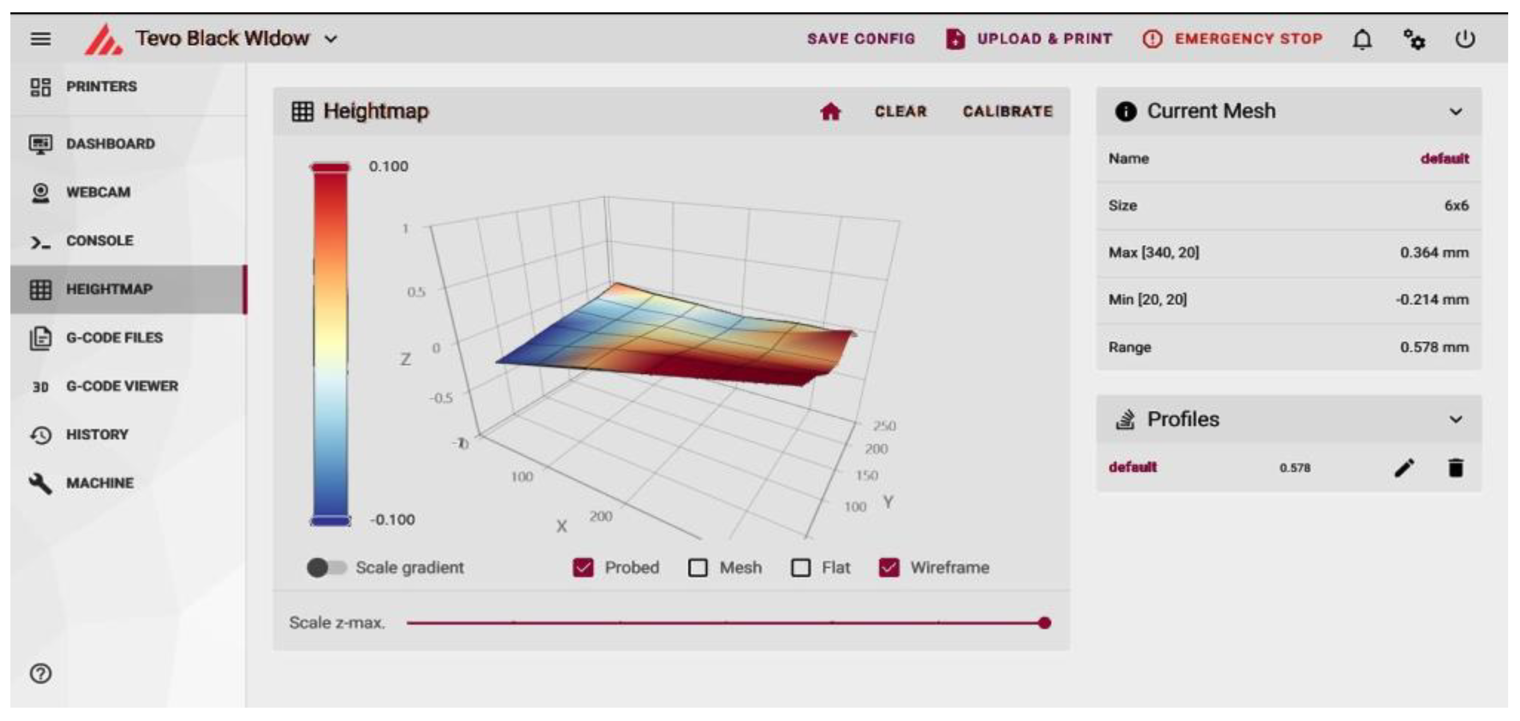
Figure 3.
Bed mesh of glass bed.
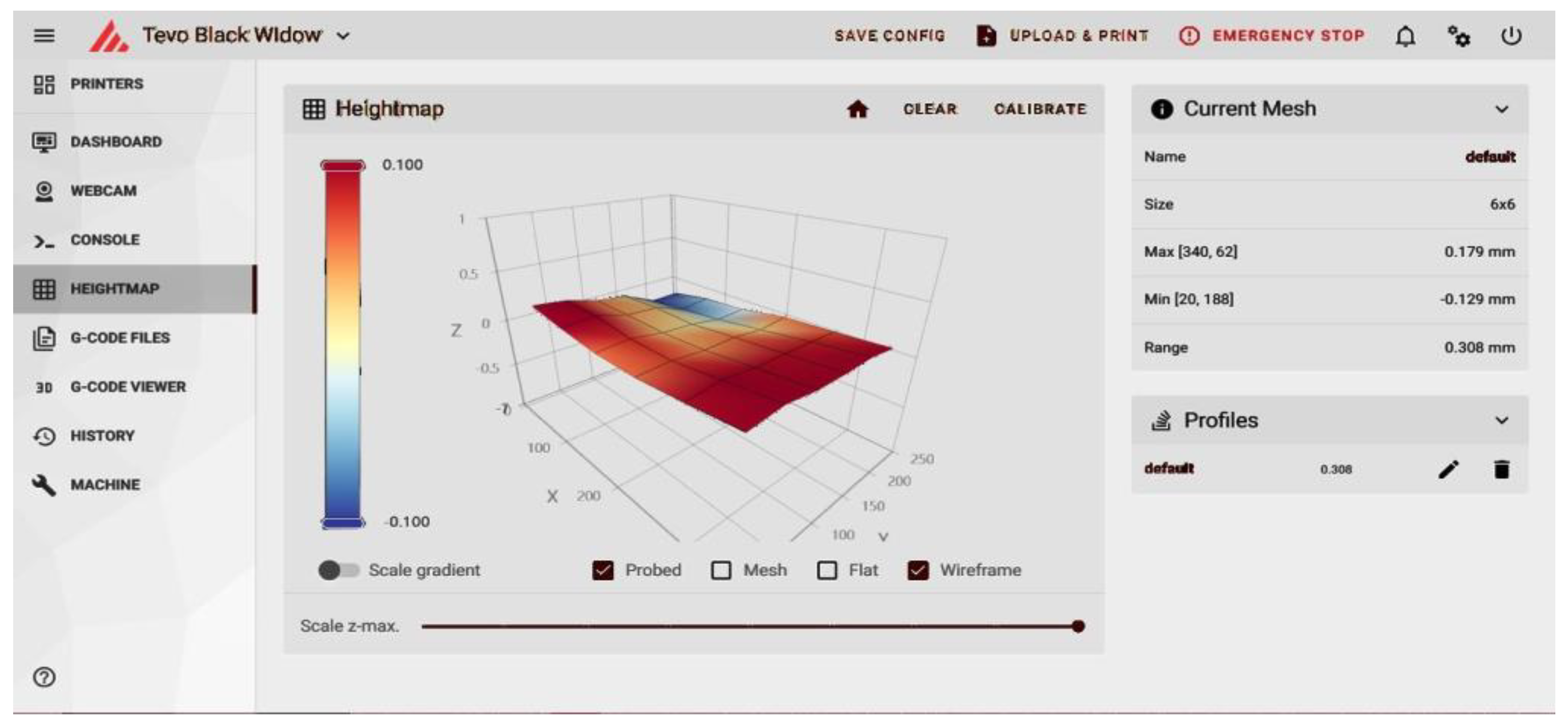
Figure 4.
Bed temperature fluctuations (blue line).
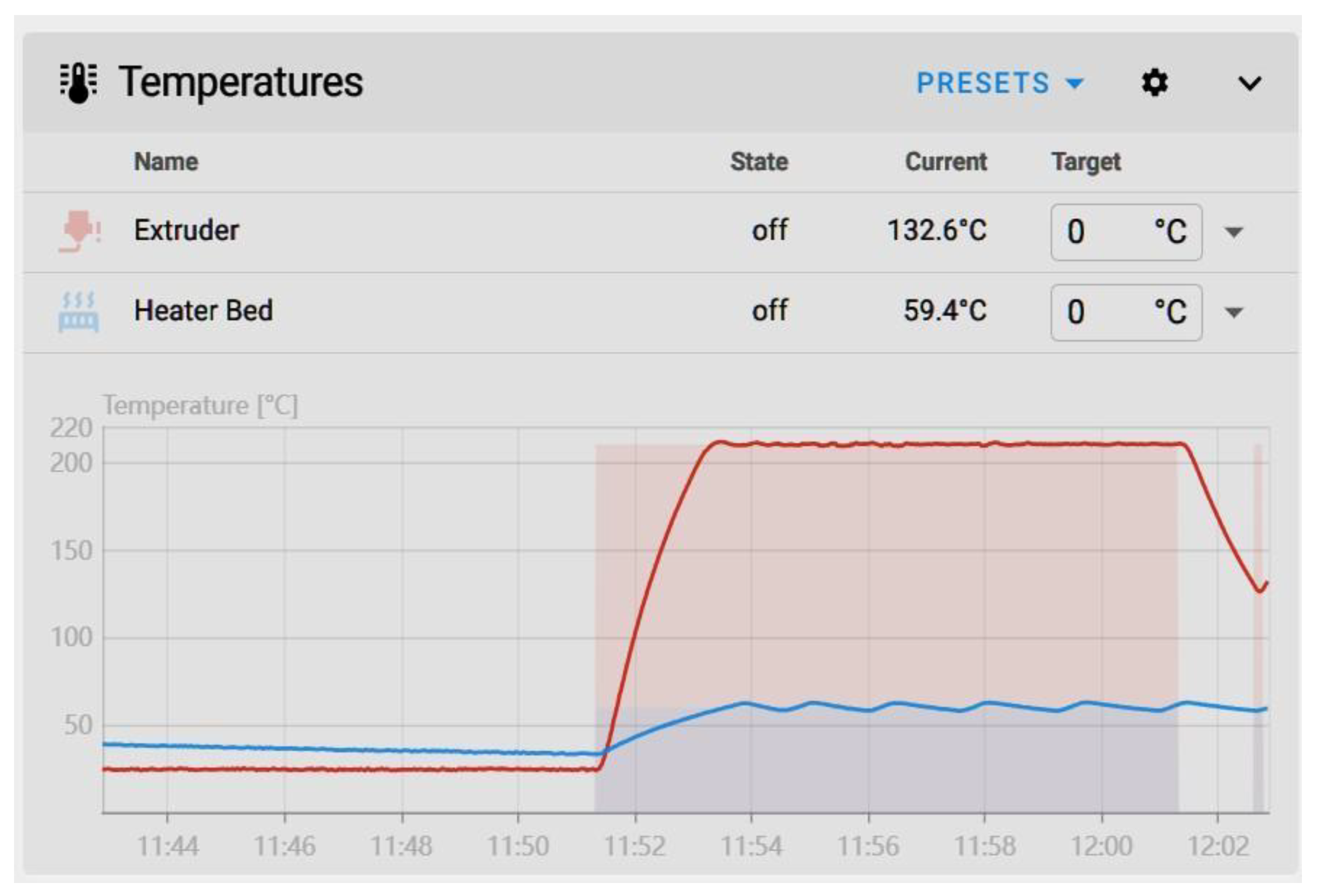
Figure 6.
Cube before PID (left) next to cube after PID tuning (right).
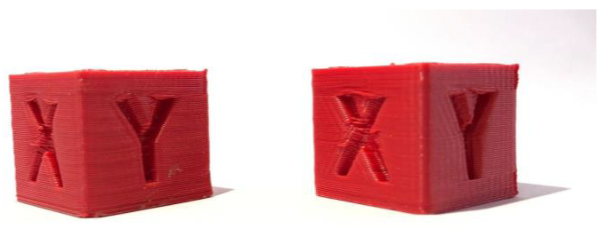
Figure 7.
Graph generated by the stand-alone script for the X-axis.
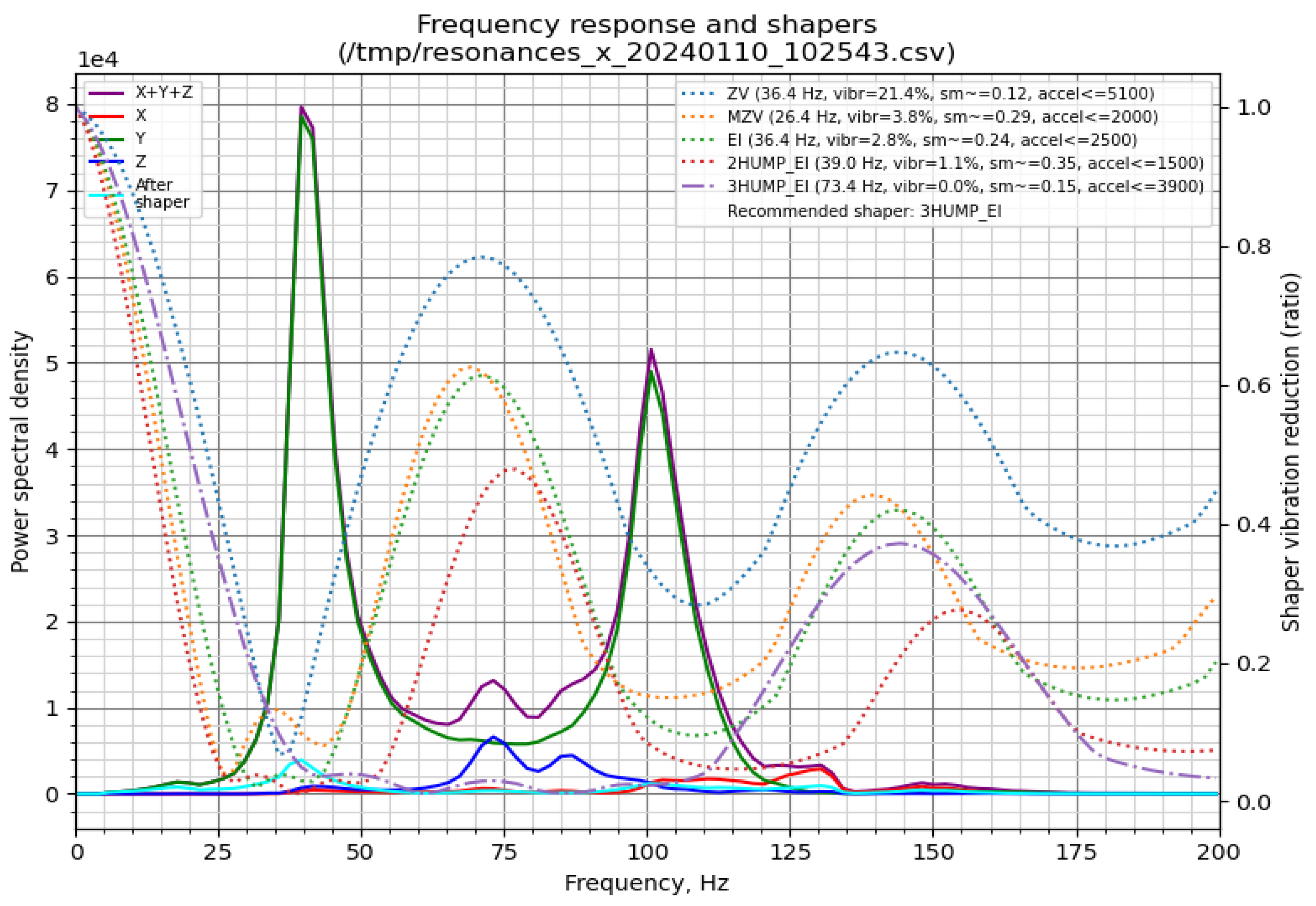
Figure 8.
Graph generated by the stand-alone script for the Y-axis.
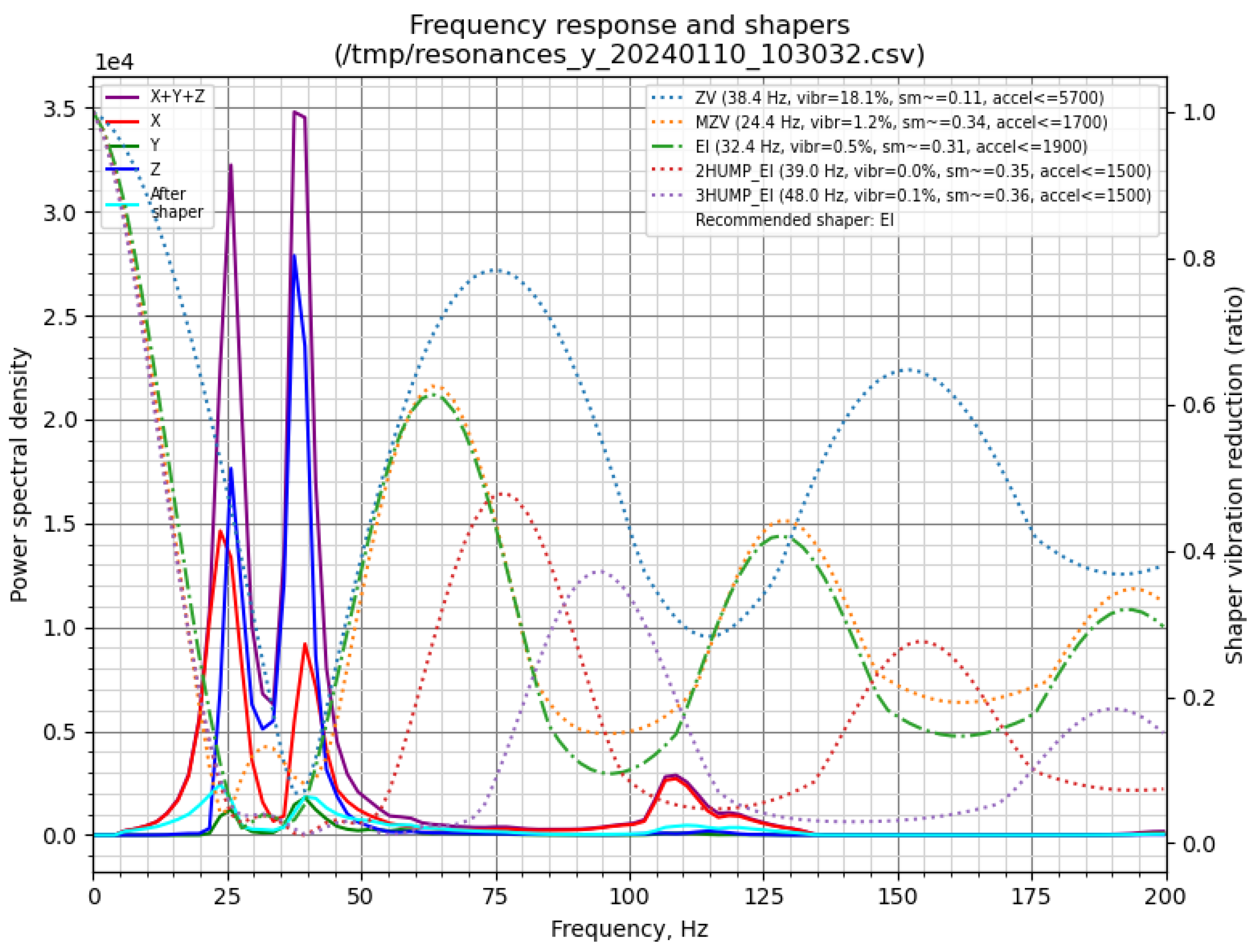
Figure 9.
Cube without Input Shaper (left), cube with Input Shaper (right).
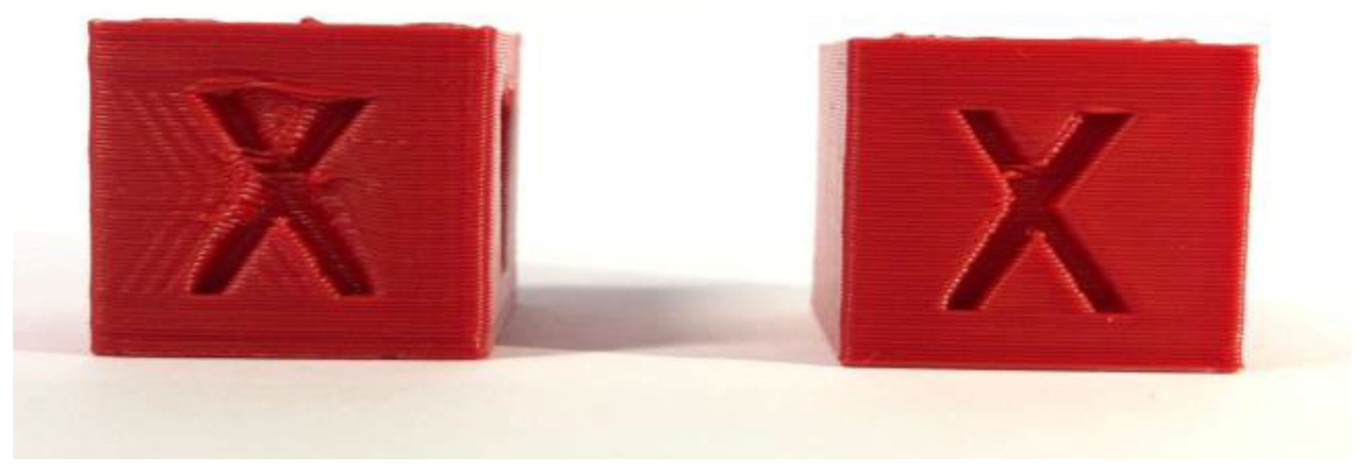
Figure 10.
Extruder moves following [21].
Figure 10.
Extruder moves following [21].
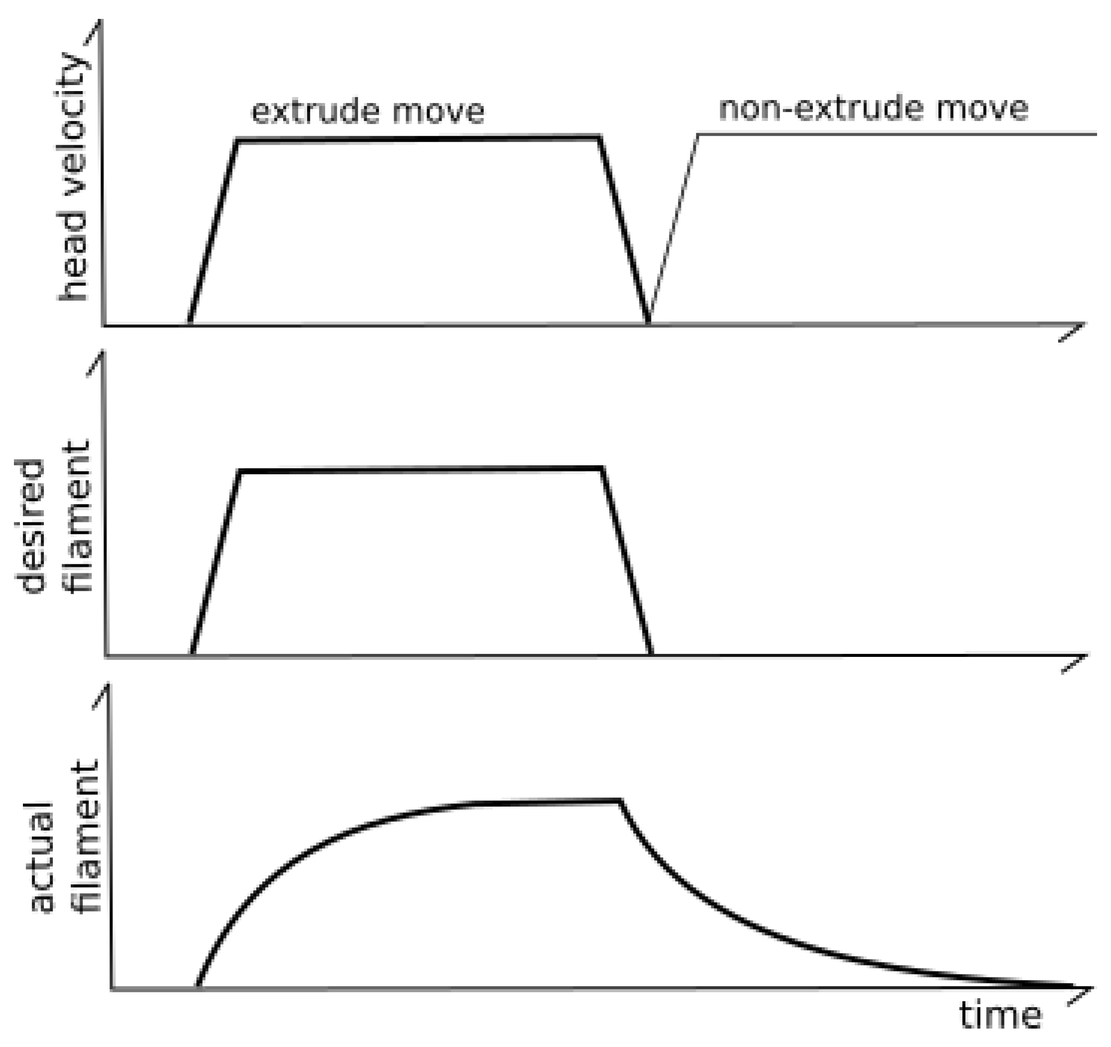
Figure 11.
Extruder velocity over time PA graph from the Klipper3D website.
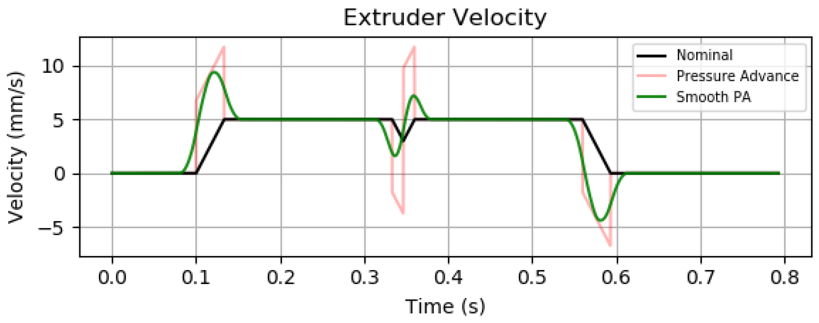
Figure 12.
Representation of the change in corner shape.
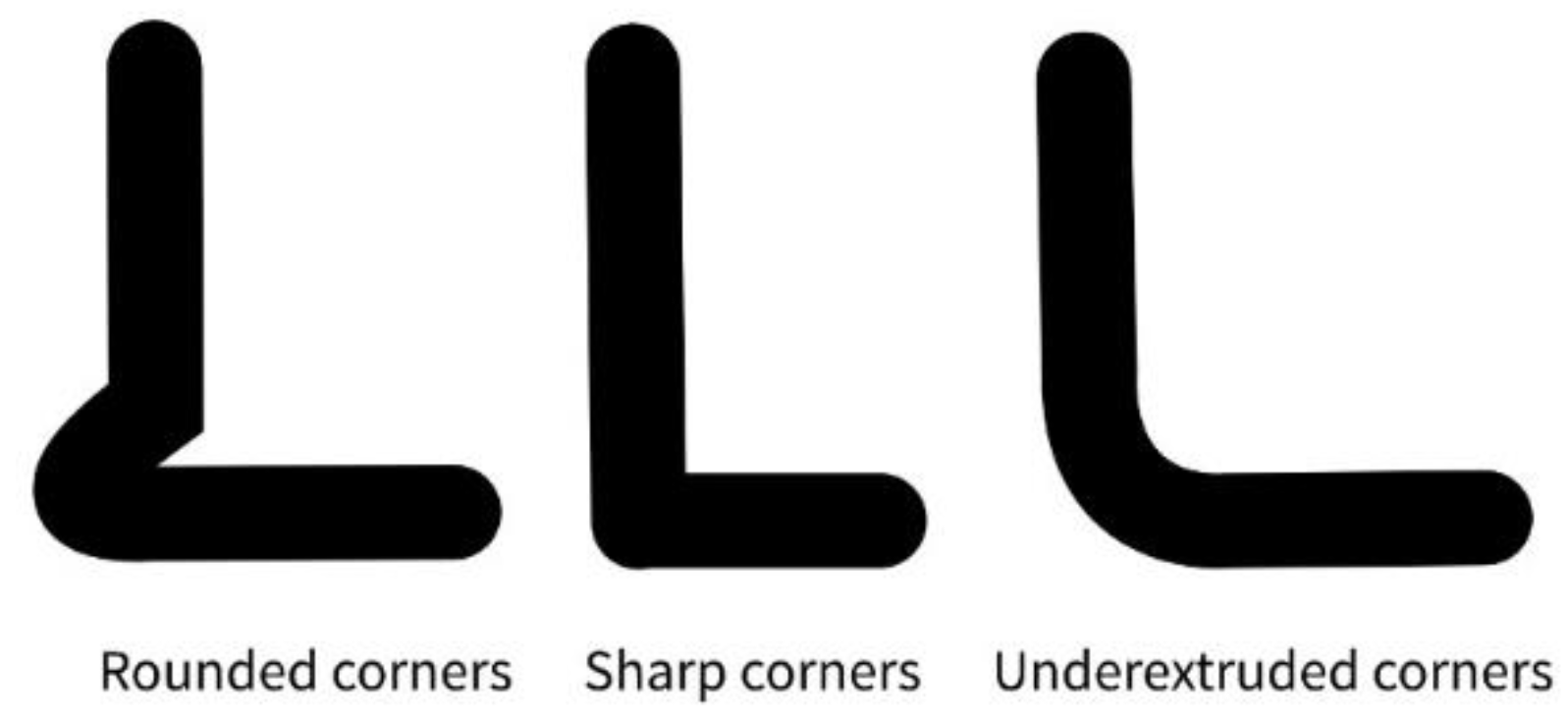
Figure 13.
Pressure Advance Tower with a marking at the height with the sharpest corners.
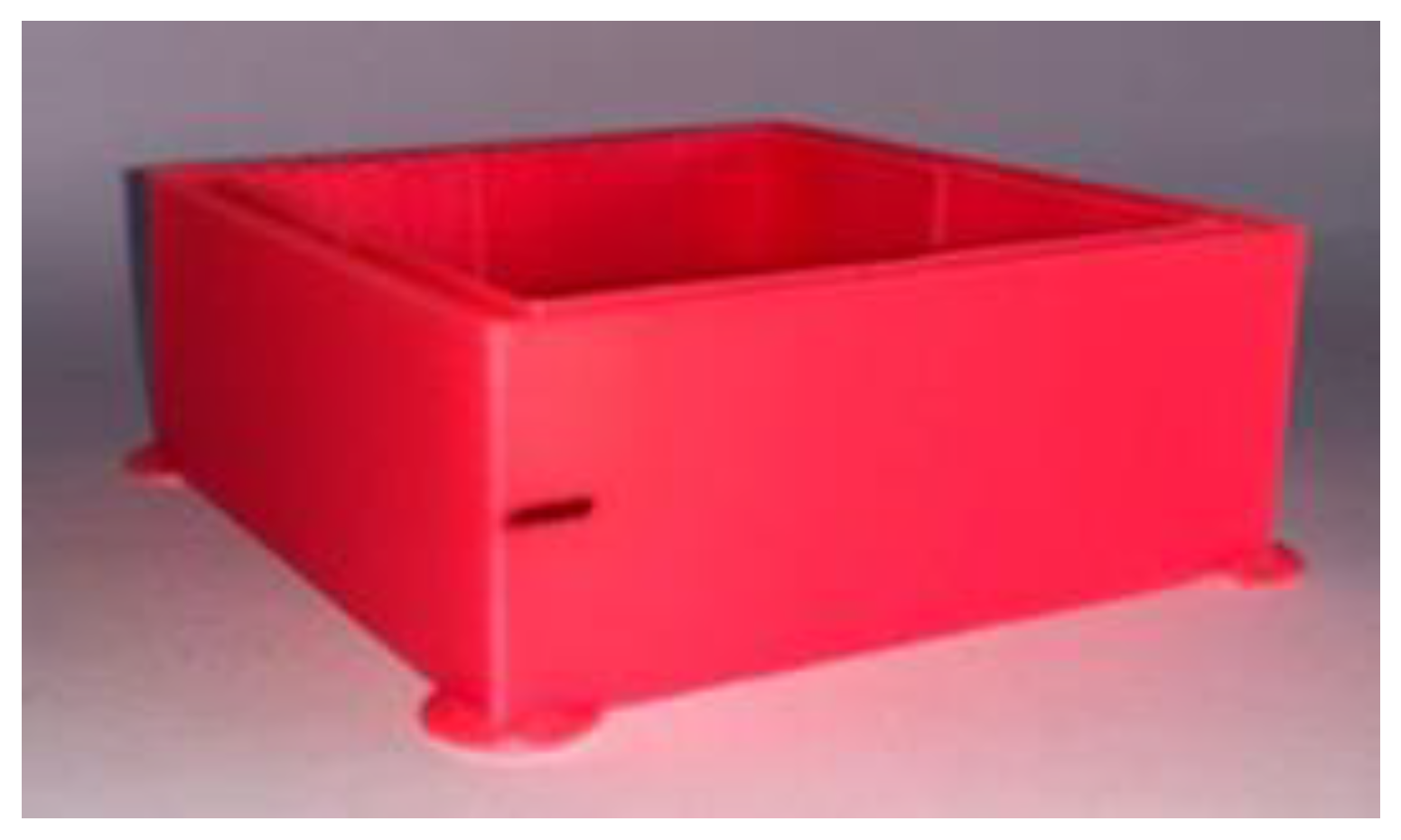

Table 1.
Comparative Table of Input Shapers.
| Scheme . | Vibration Reduction | Print Quality (Ghosting) | Execution Delay | Notes |
| ZV | Basic | Medium | Low | Simplest form, fast but limited |
| MZV | Good | Better than ZV | Slightly more | Compromise between reduction and delay |
| EI | Robust | Good | Moderate | Insensitive to resonance drift |
| 2HUMP_EI | Very good | Low ghosting | Higher | Better smoothing of high-frequency noise |
| 3HUMP_EI | Excellent | Minimal ghosting | Highest | Best for high-speed printers with complex resonance |
Disclaimer/Publisher’s Note: The statements, opinions and data contained in all publications are solely those of the individual author(s) and contributor(s) and not of MDPI and/or the editor(s). MDPI and/or the editor(s) disclaim responsibility for any injury to people or property resulting from any ideas, methods, instructions or products referred to in the content. |
© 2025 by the authors. Licensee MDPI, Basel, Switzerland. This article is an open access article distributed under the terms and conditions of the Creative Commons Attribution (CC BY) license (https://creativecommons.org/licenses/by/4.0/).
Copyright: This open access article is published under a Creative Commons CC BY 4.0 license, which permit the free download, distribution, and reuse, provided that the author and preprint are cited in any reuse.


